US4441604A - Pusher mechanism - Google Patents
Pusher mechanism Download PDFInfo
- Publication number
- US4441604A US4441604A US06/405,960 US40596082A US4441604A US 4441604 A US4441604 A US 4441604A US 40596082 A US40596082 A US 40596082A US 4441604 A US4441604 A US 4441604A
- Authority
- US
- United States
- Prior art keywords
- link
- paddle
- arm
- belt
- paddles
- Prior art date
- Legal status (The legal status is an assumption and is not a legal conclusion. Google has not performed a legal analysis and makes no representation as to the accuracy of the status listed.)
- Expired - Lifetime
Links
- 230000007246 mechanism Effects 0.000 title claims abstract description 40
- 230000006378 damage Effects 0.000 description 8
- 230000008901 benefit Effects 0.000 description 2
- 239000000463 material Substances 0.000 description 2
- 230000008859 change Effects 0.000 description 1
- 239000003638 chemical reducing agent Substances 0.000 description 1
- 238000010276 construction Methods 0.000 description 1
- 230000009977 dual effect Effects 0.000 description 1
- 230000008030 elimination Effects 0.000 description 1
- 238000003379 elimination reaction Methods 0.000 description 1
- 230000005484 gravity Effects 0.000 description 1
- 230000004048 modification Effects 0.000 description 1
- 238000012986 modification Methods 0.000 description 1
- 230000009467 reduction Effects 0.000 description 1
Images


Classifications
-
- B—PERFORMING OPERATIONS; TRANSPORTING
- B65—CONVEYING; PACKING; STORING; HANDLING THIN OR FILAMENTARY MATERIAL
- B65G—TRANSPORT OR STORAGE DEVICES, e.g. CONVEYORS FOR LOADING OR TIPPING, SHOP CONVEYOR SYSTEMS OR PNEUMATIC TUBE CONVEYORS
- B65G47/00—Article or material-handling devices associated with conveyors; Methods employing such devices
- B65G47/74—Feeding, transfer, or discharging devices of particular kinds or types
- B65G47/84—Star-shaped wheels or devices having endless travelling belts or chains, the wheels or devices being equipped with article-engaging elements
- B65G47/846—Star-shaped wheels or wheels equipped with article-engaging elements
Definitions
- the present invention pertains to the material handling conveyor art and, more particularly, to an improved pusher mechanism for use therein.
- Pusher mechanisms of various types have long been used in material handling conveyor applications to sort boxes or similar uniformly sized and shaped articles onto accumulators or chutes. Recently, these devices have also been applied to the sorting of airline baggage, which baggage is characterized by its non-uniformity in size and shape. Unlike articles normally sorted on package conveyors, consecutive articles of baggage may vary significantly in size, weight, center of gravity and friction coefficient with the conveyor belt. Additionally, baggage articles tend to be more fragile and more easily damaged by automated handling equipment. Such damage may be physical damage to the bags contents as well as the bag itself or destruction of routing tags or labels, resulting in missorting and misrouting of the baggage.
- a paddle is moved with rectilinear motion transversely across the conveyor belt, thereby engaging and shoving the bag off of the belt.
- Such a system requires a time delay in the complete cycle to allow engagement of the object with the paddle face. This time delay becomes a significant part of the complete cycle time at high cycle rates resulting in excessively high paddle speeds.
- this prior art configuration has no component of motion parallel to the conveyor belt. The paddle speed must be quite high and slippage is likely between the object and the paddle face. Considerable opportunity for physical damage and missorting of the object results.
- a single paddle is driven by a parallel link mechanism in a circular pattern across the conveyor belt.
- this single paddle configuration requires a significant time delay for a complete cycle of operation.
- This system is superior to the rectilinear motion paddle arrangement in that there is a component of paddle motion parallel to, and in the same direction as, the conveyor belt over the second half cycle of operation.
- this advantage is negated by the first half of the cycle which has a component opposed to the belt flow. This tends to increase the slippage with resulting jams and missorts.
- a third prior art pusher mechanism has dual paddles, with each paddle provided on the end of an arm which rotates on a center adjacent to the side of the conveyor bed.
- this system having two paddles moving in a semicircular pattern across the conveyor belt, does not require a time delay for engagement since the "working" paddle is returning to its home position "downstream" of the paddle preparing to push the next object.
- Paddle arm radius is approximately equal to the belt width and minimum object spacing on the conveyor belt is equal to the length of the paddle arm. Elimination of the requirement for engagement time as in the above-described systems permits slower pusher speeds for the same cycle rate.
- a component of motion of the paddle in the direction of belt travel exists to a varying degree throughout the paddle travel.
- the improved pusher mechanism includes a link which is rotatably driven at one end thereof.
- An arm is pivotally mounted to the free end of the link at a central location of the arm.
- a pair of paddles are provided, each paddle being pivotally mounted to an end of the arm.
- Drive means rotatably drives the link, arm and paddles in predetermined directions and at predetermined speeds such that each paddle is controllably driven from a rest position into engagement with an object for the controlled deflection thereof, with the paddle thereafter returning to a rest position.
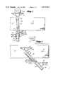
- FIGS. 1-4 are top views illustrating operation of the improved pusher mechanism through one complete cycle of operation.
- FIG. 5 is a detailed cross-sectional view of the preferred embodiment of the improved pusher mechanism.
- FIG. 1 illustrates the pusher mechanism, indicated generally at 10, positioned adjacent a conventional belt-type conveyor 12.
- the conveyor moves in the direction indicated by arrow 14 whereby objects, such as object 16, pass past the pusher mechanism 10.
- Main drive for the pusher mechanism 10 is provided by a motor 20.
- Motor 20 via a pulley, belt and gear reduction unit, all of which are more clearly shown in FIG. 5, rotatively drives a shaft 22.
- a link 24 Connected at one end to this shaft for rotation therewith is a link 24. Via the drive mechanism, the link 24 is driven about the shaft 22 in a clockwise direction at a speed ⁇ 1 during operation of the pusher mechanism.
- Arm 26 Pivotally mounted to the free end of the link 24, at a central location thereof, is an arm 26.
- Arm 26 is rotatably driven around the free end of link 24 via a pair of sprockets 28, 30, and a chain (or timing belt) 32.
- the sprocket ratio is such that arm 26 rotates at a speed ⁇ 2 which is one-half of ⁇ 1 and in an opposite direction.
- paddles 34, 36 Attached at each end of arm 26 are paddles 34, 36.
- the paddles 34, 36 are provided with engaging face surfaces 40, 42, respectively, which are adapted for engaging with objects on the belt 12.
- Each paddle 40, 42 is rotatably driven via sprocket 30, chains 44, 46, and sprockets 48, 50.
- the rotational speed ⁇ 3 of each paddle is equal to, but opposite that of, the arm speed ⁇ 2 .
- FIG. 1 illustrates the pusher mechanism 10 in its rest position. Operation of the mechanism through one complete pusher mechanism cycle is illustrated in FIGS. 2 through 4.
- link 24 has rotated 90° in a clockwise direction, with the arm 26 having rotated 45° in a counter-clockwise direction.
- Paddle 36 has rotated 45° in rotation opposite to that of arm 26. The relative rotations of these parts, as shown, have caused the face 42 of paddle 36 to forcibly engage the object 16 and begin transversely moving the object off of the belt 12.
- the arrangement is such that the longitudinal axis of the face 42 will remain parallel to the direction of travel of the belt throughout engagement of the paddle face 42 with the object 16.
- the mechanism has gone through one full half cycle with link 24 rotated 180° and the arm 26 and paddle 36 having rotated a total of 90° from their original positions. As shown, the mechanism is at its full extension across the belt, completely deflecting the object 16 off of the belt and into a chute or other utilization means.
- a particular feature of this construction is that the travel of the pusher mechanism across the conveyor belt is the sum of the arm 26 radius and twice the length of link 24. Thus, over the travel of paddle 36 across belt 12, the length of the arm 26 is reduced by twice the length of link 24. Since belt speed is a function of the length of arm 26 and cycle rate, the present pusher mechanism requires a lower belt speed than systems known to the prior art for the same cycle rate.
- the pattern traced by the paddles is very close to that of an equilateral triangle.
- This pattern has two important advantages. Firstly, the component of paddle speed parallel to the belt is almost equal to the belt speed. Thus, damage to objects being pushed from the belt is reduced to a minimum.
- the pattern traced by the paddle during the return stroke from the "downstream" position to the start position is very close to a straight line parallel to, and in close proximity of, the conveyor bed. As such, the mechanism occupies a minimum space adjacent to the conveyor.
- FIG. 5 is a detailed cross-sectional view of the preferred embodiment of the pusher mechanism as shown in FIGS. 1-4.
- rotational speeds of the preferred embodiment of the invention are given, it being understood that this in no way limits the scope of the invention.
- a motor 20 operates at 1725 RPM. Adjacent the motor is a conventional clutch/brake mechanism 100. Drive from the motor is taken off of shaft 102 to which is connected a pulley 104. A vee belt 106 transmits the rotational drive to a pulley 108 attached to a shaft 110. A reducer 112 reduces the speed by 25.64/1, with the resultant drive being applied to the shaft 22. Shaft 22 is connected to link 24 whereby link 24 rotates at 67.2 RPM. A 72-tooth sprocket 28 on shaft 22 transmits drive via a chain 32 to a 48-tooth sprocket 30a on shaft 114. The ratio between sprockets 28 and 30a is, therefore, 1.5/1.
- shaft 114 Provided on shaft 114 are a pair of sprockets 30b, 30c, each of 24 teeth. These sprockets, via chains 44, 46 drive 72-tooth sprockets 48, 50 and, thereby, paddles 34, 36.
- the 1.5/1 ratio in the sprocket 30a produces a rotation of -1.5 revolutions of the sprocket when the link 24 rotates +1 revolution.
- the arm 26, attached to the sprocket 30a rotates -1.5 revolutions relative to the link 24 with a net change of position with respect to ground of -1/2 revolution.
- the 24-tooth sprockets 30b, 30c affixed to the end of the shaft 114 rotate +1 revolution for +1 revolution of rotation of the link 24.
- the arm 26 is rotated -1/2 revolution, resulting in +1.5 revolutions of the sprocket 30a relative to the arm 26.
- the 3:1 ratio of the sprockets in arm 26 produces a paddle rotation of +1/2 revolution while the arm 26 is rotating -1/2 revolution or a net paddle rotation, with respect to ground, of 0°.
- an improved pusher mechanism which is capable of high-speed operation with a minimum of damage to the objects being diverted and which consumes a minimum of space adjacent to the conveyor belt.
Landscapes
- Engineering & Computer Science (AREA)
- Mechanical Engineering (AREA)
- Special Conveying (AREA)
Abstract
Description
______________________________________
                                  PRESENT
          TYPE  TYPE     TYPE     INVEN-
          (1)   (2)      (3)      TION
______________________________________
Paddle Motion
            Recti-  Circular Semi-  Triangular
            linear           circular
Peak Paddle 19.6    12.8     12.8   8.1
Speed Across
            (Varies)
                    (Varies) (Varies)
                                    (Constant)
Belt (Ft./Sec.)
Cycle Time  0.8     0.8      0.8    0.8
(Sec.)
Object Spacing
            6.7     6.5      6.5    4.0
(Ft.)
Belt Speed (FPM)
            500     488      488    300
______________________________________
Claims (4)
Priority Applications (1)
| Application Number | Priority Date | Filing Date | Title |
|---|---|---|---|
| US06/405,960 US4441604A (en) | 1982-06-24 | 1982-06-24 | Pusher mechanism |
Applications Claiming Priority (1)
| Application Number | Priority Date | Filing Date | Title |
|---|---|---|---|
| US06/405,960 US4441604A (en) | 1982-06-24 | 1982-06-24 | Pusher mechanism |
Publications (1)
| Publication Number | Publication Date |
|---|---|
| US4441604A true US4441604A (en) | 1984-04-10 |
Family
ID=23605944
Family Applications (1)
| Application Number | Title | Priority Date | Filing Date |
|---|---|---|---|
| US06/405,960 Expired - Lifetime US4441604A (en) | 1982-06-24 | 1982-06-24 | Pusher mechanism |
Country Status (1)
| Country | Link |
|---|---|
| US (1) | US4441604A (en) |
Cited By (32)
| Publication number | Priority date | Publication date | Assignee | Title |
|---|---|---|---|---|
| US4643291A (en) * | 1986-01-21 | 1987-02-17 | Rexnord Inc. | Linear articulated pusher |
| US4813528A (en) * | 1987-02-06 | 1989-03-21 | Dominion Chain Inc. | Conveyor loading system |
| US5931281A (en) * | 1995-05-04 | 1999-08-03 | Maschinen-Und Stahlbau Julius Lippert Gmbh & Co. | Transfer device |
| US5992609A (en) * | 1997-09-15 | 1999-11-30 | Grapha-Holding Ag | Apparatus for sorting by directing individual pieces |
| US6011508A (en) * | 1997-10-31 | 2000-01-04 | Magnemotion, Inc. | Accurate position-sensing and communications for guideway operated vehicles |
| US6041910A (en) * | 1997-09-22 | 2000-03-28 | Jervis B. Webb Company | Baggage pusher device and system |
| US6068105A (en) * | 1997-09-19 | 2000-05-30 | Mannesmann Dematic Rapistan Corp. | Low impact article diverter assembly |
| US6101952A (en) * | 1997-12-24 | 2000-08-15 | Magnemotion, Inc. | Vehicle guidance and switching via magnetic forces |
| US6220422B1 (en) | 1998-12-28 | 2001-04-24 | G & T Conveyor Company, Inc. | Rotary articulated pusher for removing items, such as luggage, from a conveyor belt |
| US6446782B1 (en) | 2000-06-16 | 2002-09-10 | Rapistan Systems Advertising Corp. | Shuttle top diverter |
| US6505733B2 (en) | 2001-01-12 | 2003-01-14 | Rapistan Systems Advertising Corp. | Right angle power transfer |
| US6543602B1 (en) * | 1997-01-22 | 2003-04-08 | United Parcel Service Of America, Inc. | Automated lateral translation conveyor |
| US6607065B2 (en) | 2000-08-11 | 2003-08-19 | Rapistan Systems Advertising Corp. | High speed baggage diverter |
| US20040119358A1 (en) * | 2001-10-01 | 2004-06-24 | Thornton Richard D. | Suspending, guiding and propelling vehicles using magnetic forces |
| US6755298B1 (en) * | 1997-09-12 | 2004-06-29 | Heuft Systemtechnik Gmbh | Device for outward guidance of articles transported on a conveyer |
| US6781524B1 (en) | 2000-03-17 | 2004-08-24 | Magnemotion, Inc. | Passive position-sensing and communications for vehicles on a pathway |
| US20040231960A1 (en) * | 2003-03-21 | 2004-11-25 | Wolf Stephen C. | Diverter |
| US6917136B2 (en) | 2001-10-01 | 2005-07-12 | Magnemotion, Inc. | Synchronous machine design and manufacturing |
| US20050263369A1 (en) * | 2004-05-07 | 2005-12-01 | Magnemotion, Inc. | Three-dimensional motion using single-pathway based actuators |
| US20050263370A1 (en) * | 2004-05-17 | 2005-12-01 | Peppel George W | High speed baggage diverter |
| US20070044676A1 (en) * | 2005-07-22 | 2007-03-01 | Magnemotion Inc. | Guideway activated magnetic switching of vehicles |
| US20070246328A1 (en) * | 2004-06-21 | 2007-10-25 | Siemens Corporate Research Inc. | High-Rate Space Efficient Article Singulator |
| US20080000753A1 (en) * | 2006-03-06 | 2008-01-03 | Patterson Rafe T | Offset overhead plunger |
| US20090257856A1 (en) * | 2008-04-11 | 2009-10-15 | Bottero S.P.A | Transfer assembly for transferring glass articles |
| EP2332866A1 (en) * | 2009-12-11 | 2011-06-15 | Wincor Nixdorf International GmbH | Container sorting device |
| US8483895B1 (en) | 2009-02-25 | 2013-07-09 | James J. Beregi | Transportation system, system components and process |
| US20150352596A1 (en) * | 2013-01-17 | 2015-12-10 | Ishida Co., Ltd. | Inspection system |
| US9327914B1 (en) * | 2013-08-22 | 2016-05-03 | Millard Manufacturing Corp. | Rotary sweep arm system |
| US9346371B2 (en) | 2009-01-23 | 2016-05-24 | Magnemotion, Inc. | Transport system powered by short block linear synchronous motors |
| US9771000B2 (en) | 2009-01-23 | 2017-09-26 | Magnemotion, Inc. | Short block linear synchronous motors and switching mechanisms |
| US9802507B2 (en) | 2013-09-21 | 2017-10-31 | Magnemotion, Inc. | Linear motor transport for packaging and other uses |
| US20240018963A1 (en) * | 2020-11-27 | 2024-01-18 | Paddlemover Llc | Material Mover |
Citations (1)
| Publication number | Priority date | Publication date | Assignee | Title |
|---|---|---|---|---|
| US3083808A (en) * | 1961-08-30 | 1963-04-02 | Standard Conveyor Co | Transfer mechanism for conveyors |
-
1982
- 1982-06-24 US US06/405,960 patent/US4441604A/en not_active Expired - Lifetime
Patent Citations (1)
| Publication number | Priority date | Publication date | Assignee | Title |
|---|---|---|---|---|
| US3083808A (en) * | 1961-08-30 | 1963-04-02 | Standard Conveyor Co | Transfer mechanism for conveyors |
Cited By (47)
| Publication number | Priority date | Publication date | Assignee | Title |
|---|---|---|---|---|
| US4643291A (en) * | 1986-01-21 | 1987-02-17 | Rexnord Inc. | Linear articulated pusher |
| US4813528A (en) * | 1987-02-06 | 1989-03-21 | Dominion Chain Inc. | Conveyor loading system |
| US5931281A (en) * | 1995-05-04 | 1999-08-03 | Maschinen-Und Stahlbau Julius Lippert Gmbh & Co. | Transfer device |
| US6543602B1 (en) * | 1997-01-22 | 2003-04-08 | United Parcel Service Of America, Inc. | Automated lateral translation conveyor |
| US6698571B2 (en) | 1997-01-22 | 2004-03-02 | United Parcel Service Of America, Inc. | Automated lateral translation conveyor |
| US6755298B1 (en) * | 1997-09-12 | 2004-06-29 | Heuft Systemtechnik Gmbh | Device for outward guidance of articles transported on a conveyer |
| US5992609A (en) * | 1997-09-15 | 1999-11-30 | Grapha-Holding Ag | Apparatus for sorting by directing individual pieces |
| US6068105A (en) * | 1997-09-19 | 2000-05-30 | Mannesmann Dematic Rapistan Corp. | Low impact article diverter assembly |
| US6041910A (en) * | 1997-09-22 | 2000-03-28 | Jervis B. Webb Company | Baggage pusher device and system |
| US6011508A (en) * | 1997-10-31 | 2000-01-04 | Magnemotion, Inc. | Accurate position-sensing and communications for guideway operated vehicles |
| US6101952A (en) * | 1997-12-24 | 2000-08-15 | Magnemotion, Inc. | Vehicle guidance and switching via magnetic forces |
| US6220422B1 (en) | 1998-12-28 | 2001-04-24 | G & T Conveyor Company, Inc. | Rotary articulated pusher for removing items, such as luggage, from a conveyor belt |
| US6781524B1 (en) | 2000-03-17 | 2004-08-24 | Magnemotion, Inc. | Passive position-sensing and communications for vehicles on a pathway |
| US6446782B1 (en) | 2000-06-16 | 2002-09-10 | Rapistan Systems Advertising Corp. | Shuttle top diverter |
| US6607065B2 (en) | 2000-08-11 | 2003-08-19 | Rapistan Systems Advertising Corp. | High speed baggage diverter |
| USRE41360E1 (en) | 2000-08-11 | 2010-06-01 | Siemens Industry, Inc. | High speed baggage diverter |
| US6505733B2 (en) | 2001-01-12 | 2003-01-14 | Rapistan Systems Advertising Corp. | Right angle power transfer |
| US20040119358A1 (en) * | 2001-10-01 | 2004-06-24 | Thornton Richard D. | Suspending, guiding and propelling vehicles using magnetic forces |
| US6917136B2 (en) | 2001-10-01 | 2005-07-12 | Magnemotion, Inc. | Synchronous machine design and manufacturing |
| US20050242675A1 (en) * | 2001-10-01 | 2005-11-03 | Magnemotion, Inc. | Synchronous machine design and manufacturing |
| US6983701B2 (en) | 2001-10-01 | 2006-01-10 | Magnemotion, Inc. | Suspending, guiding and propelling vehicles using magnetic forces |
| US20060130699A1 (en) * | 2001-10-01 | 2006-06-22 | Magnemotion, Inc. | Suspending, guiding and propelling vehicles using magnetic forces |
| US7448327B2 (en) | 2001-10-01 | 2008-11-11 | Magnemotion, Inc. | Suspending, guiding and propelling vehicles using magnetic forces |
| US7538469B2 (en) | 2001-10-01 | 2009-05-26 | Magnemotion, Inc. | Synchronous machine design and manufacturing |
| US20040231960A1 (en) * | 2003-03-21 | 2004-11-25 | Wolf Stephen C. | Diverter |
| US7124876B2 (en) * | 2003-03-21 | 2006-10-24 | Dematic Corp. | Diverter |
| US20050263369A1 (en) * | 2004-05-07 | 2005-12-01 | Magnemotion, Inc. | Three-dimensional motion using single-pathway based actuators |
| US7926644B2 (en) | 2004-05-07 | 2011-04-19 | Magnemotion, Inc. | Three-dimensional motion using single-pathway based actuators |
| US7458454B2 (en) | 2004-05-07 | 2008-12-02 | Magnemotion, Inc. | Three-dimensional motion using single-pathway based actuators |
| US6974020B1 (en) | 2004-05-17 | 2005-12-13 | Peppel George W | High speed baggage diverter |
| US20050263370A1 (en) * | 2004-05-17 | 2005-12-01 | Peppel George W | High speed baggage diverter |
| US20070246328A1 (en) * | 2004-06-21 | 2007-10-25 | Siemens Corporate Research Inc. | High-Rate Space Efficient Article Singulator |
| US20070044676A1 (en) * | 2005-07-22 | 2007-03-01 | Magnemotion Inc. | Guideway activated magnetic switching of vehicles |
| US20080000753A1 (en) * | 2006-03-06 | 2008-01-03 | Patterson Rafe T | Offset overhead plunger |
| US7410045B2 (en) * | 2006-03-06 | 2008-08-12 | Meadwestvaco Packaging Systems, Llc | Offset overhead plunger |
| US20090257856A1 (en) * | 2008-04-11 | 2009-10-15 | Bottero S.P.A | Transfer assembly for transferring glass articles |
| US7975832B2 (en) * | 2008-04-11 | 2011-07-12 | Bottero S.P.A. | Transfer assembly for transferring glass articles |
| US9346371B2 (en) | 2009-01-23 | 2016-05-24 | Magnemotion, Inc. | Transport system powered by short block linear synchronous motors |
| US10112777B2 (en) | 2009-01-23 | 2018-10-30 | Magnemotion, Inc. | Transport system powered by short block linear synchronous motors |
| US9771000B2 (en) | 2009-01-23 | 2017-09-26 | Magnemotion, Inc. | Short block linear synchronous motors and switching mechanisms |
| US8483895B1 (en) | 2009-02-25 | 2013-07-09 | James J. Beregi | Transportation system, system components and process |
| EP2332866A1 (en) * | 2009-12-11 | 2011-06-15 | Wincor Nixdorf International GmbH | Container sorting device |
| US9522414B2 (en) * | 2013-01-17 | 2016-12-20 | Ishida Co., Ltd. | Inspection system |
| US20150352596A1 (en) * | 2013-01-17 | 2015-12-10 | Ishida Co., Ltd. | Inspection system |
| US9327914B1 (en) * | 2013-08-22 | 2016-05-03 | Millard Manufacturing Corp. | Rotary sweep arm system |
| US9802507B2 (en) | 2013-09-21 | 2017-10-31 | Magnemotion, Inc. | Linear motor transport for packaging and other uses |
| US20240018963A1 (en) * | 2020-11-27 | 2024-01-18 | Paddlemover Llc | Material Mover |
Similar Documents
| Publication | Publication Date | Title |
|---|---|---|
| US4441604A (en) | Pusher mechanism | |
| US4264002A (en) | Divider switch for roller conveyors | |
| US5217104A (en) | Device for deviating objects traveling on a conveyor | |
| EP0056946B1 (en) | An arrangement for the feeding of objects | |
| US4711357A (en) | Automated system and method for transporting and sorting articles | |
| US5010998A (en) | Diverter | |
| CA2055537A1 (en) | Container Grouping Apparatus | |
| EP0113340B1 (en) | Pusher mechanism | |
| US5551551A (en) | Article combiner with multiple conveying surfaces and moving guides | |
| JP2008514525A (en) | Apparatus and method for high speed conveyor switching | |
| RU95118713A (en) | INSTALLATION FOR TEMPORARY STORAGE OF PRODUCTS | |
| US4054201A (en) | Luggage sortation device | |
| US4463846A (en) | Bottle orienting apparatus | |
| KR940000008A (en) | Egg collector | |
| US7114608B2 (en) | Directional transition module for use in conjunction with a roller-type conveyor | |
| US4881929A (en) | Stop and go conveyor | |
| US4917229A (en) | Method and apparatus for stacking products | |
| CN217222461U (en) | Seeding mechanism and sorting system | |
| ES2043047T3 (en) | DEVICE FOR THE TRANSPORT OF OBJECTS, MAINLY FRUITS AND VEGETABLES WITH PARTICULAR VIEWS OF THEIR QUALITY CONTROL. | |
| GB2087336A (en) | Carton collating and transfer apparatus | |
| SU1283185A1 (en) | Inertia conveyer | |
| SU679491A1 (en) | Apparatus for sorting articles on conveyer | |
| GB2278329A (en) | Conveyor to space articles equally | |
| KR860000196B1 (en) | Method and device for stacking long members | |
| SU1177232A1 (en) | Oscillating conveyer |
Legal Events
| Date | Code | Title | Description |
|---|---|---|---|
| AS | Assignment |
Owner name: BAE AUTOMATED SYSTEMS, INC., 2525 CARTER, CARROLLT Free format text: ASSIGNMENT OF ASSIGNORS INTEREST.;ASSIGNOR:BOEING COMPANY THE;REEL/FRAME:004148/0379 Effective date: 19830517 |
|
| STCF | Information on status: patent grant |
Free format text: PATENTED CASE |
|
| MAFP | Maintenance fee payment |
Free format text: PAYMENT OF MAINTENANCE FEE, 4TH YEAR, PL 96-517 (ORIGINAL EVENT CODE: M170); ENTITY STATUS OF PATENT OWNER: LARGE ENTITY Year of fee payment: 4 |
|
| MAFP | Maintenance fee payment |
Free format text: PAYMENT OF MAINTENANCE FEE, 8TH YEAR, PL 96-517 (ORIGINAL EVENT CODE: M171); ENTITY STATUS OF PATENT OWNER: LARGE ENTITY Year of fee payment: 8 |
|
| FEPP | Fee payment procedure |
Free format text: PAYOR NUMBER ASSIGNED (ORIGINAL EVENT CODE: ASPN); ENTITY STATUS OF PATENT OWNER: LARGE ENTITY |
|
| MAFP | Maintenance fee payment |
Free format text: PAYMENT OF MAINTENANCE FEE, 12TH YEAR, LARGE ENTITY (ORIGINAL EVENT CODE: M185); ENTITY STATUS OF PATENT OWNER: LARGE ENTITY Year of fee payment: 12 |
|
| FEPP | Fee payment procedure |
Free format text: PAT HLDR NO LONGER CLAIMS SMALL ENT STAT AS SMALL BUSINESS (ORIGINAL EVENT CODE: LSM2); ENTITY STATUS OF PATENT OWNER: LARGE ENTITY |
|
| AS | Assignment |
Owner name: ELITE LINE SERVICES, INC., FLORIDA Free format text: ASSIGNMENT OF ASSIGNORS INTEREST;ASSIGNOR:BAE AUTOMATED SYSTEMS, INC.;REEL/FRAME:013101/0411 Effective date: 20020607 |