EP2330455A1 - Contrôleur de microscope et système de microscope doté du contrôleur de microscope - Google Patents
Contrôleur de microscope et système de microscope doté du contrôleur de microscope Download PDFInfo
- Publication number
- EP2330455A1 EP2330455A1 EP10015093A EP10015093A EP2330455A1 EP 2330455 A1 EP2330455 A1 EP 2330455A1 EP 10015093 A EP10015093 A EP 10015093A EP 10015093 A EP10015093 A EP 10015093A EP 2330455 A1 EP2330455 A1 EP 2330455A1
- Authority
- EP
- European Patent Office
- Prior art keywords
- functional area
- electric
- touch panel
- unit
- physical contact
- Prior art date
- Legal status (The legal status is an assumption and is not a legal conclusion. Google has not performed a legal analysis and makes no representation as to the accuracy of the status listed.)
- Granted
Links
- 238000004891 communication Methods 0.000 claims abstract description 16
- 238000000034 method Methods 0.000 claims description 81
- 230000033001 locomotion Effects 0.000 claims description 34
- 230000003287 optical effect Effects 0.000 claims description 25
- 238000010586 diagram Methods 0.000 description 75
- 230000008569 process Effects 0.000 description 67
- 230000006870 function Effects 0.000 description 49
- 238000005286 illumination Methods 0.000 description 18
- 101000713575 Homo sapiens Tubulin beta-3 chain Proteins 0.000 description 5
- 102100036790 Tubulin beta-3 chain Human genes 0.000 description 5
- 230000005540 biological transmission Effects 0.000 description 5
- 238000007689 inspection Methods 0.000 description 3
- 230000033228 biological regulation Effects 0.000 description 2
- 230000008859 change Effects 0.000 description 2
- 230000007423 decrease Effects 0.000 description 2
- 230000003247 decreasing effect Effects 0.000 description 2
- 238000001514 detection method Methods 0.000 description 2
- 230000007246 mechanism Effects 0.000 description 2
- 101000713585 Homo sapiens Tubulin beta-4A chain Proteins 0.000 description 1
- 102100036788 Tubulin beta-4A chain Human genes 0.000 description 1
- 230000000881 depressing effect Effects 0.000 description 1
- 238000005516 engineering process Methods 0.000 description 1
- 230000005284 excitation Effects 0.000 description 1
- 238000000386 microscopy Methods 0.000 description 1
- 238000012986 modification Methods 0.000 description 1
- 230000004048 modification Effects 0.000 description 1
- 238000012545 processing Methods 0.000 description 1
- 238000011160 research Methods 0.000 description 1
Images


Classifications
-
- G—PHYSICS
- G02—OPTICS
- G02B—OPTICAL ELEMENTS, SYSTEMS OR APPARATUS
- G02B21/00—Microscopes
- G02B21/36—Microscopes arranged for photographic purposes or projection purposes or digital imaging or video purposes including associated control and data processing arrangements
- G02B21/368—Microscopes arranged for photographic purposes or projection purposes or digital imaging or video purposes including associated control and data processing arrangements details of associated display arrangements, e.g. mounting of LCD monitor
-
- G—PHYSICS
- G02—OPTICS
- G02B—OPTICAL ELEMENTS, SYSTEMS OR APPARATUS
- G02B21/00—Microscopes
- G02B21/24—Base structure
Definitions
- the present invention relates to a microscope system that has a plurality of objective lenses, performs an enlargement observation of a minute sample, and has various optical members driven by a motor.
- Microscope apparatuses are widely used for research, inspections, and the like in the field of biology industry as well as in the industrial field. If an inspection is carried out using such a microscope apparatus, an observation or inspection is performed by a microscope apparatus including a plurality of objective lenses typically with different magnifications by operating an electric stage that can move an observation sample within a plane orthogonal to a light path extending from the objective lenses.
- a microscope apparatus including a plurality of objective lenses typically with different magnifications by operating an electric stage that can move an observation sample within a plane orthogonal to a light path extending from the objective lenses.
- various component units composing the microscope apparatus e.g., various illuminators, an aperture stop, afieldstop, a revolver, an automatic focusing mechanism, an optical element switching mechanism for a lens, a filter, and the like
- an operation apparatus is connected to the microscope body; each component unit is driven in accordance with operations via the operation apparatus; and the drive status of each component unit is grasped via a display provided by the operation apparatus.
- a dedicated controller for microscopes or a microscope controller such as a PC (personal computer) is connected to the microscope body via a communication cable. Then, commands are transmitted to or received from the microscope body in accordance with the operation of the microscope controller, and various settings are established by driving and controlling each component unit.
- microscope controllers having a touch panel function for addressing many operations have started appearing.
- an optional button region is provided on the touch panel and the microscope is operated by depressing this region.
- it is necessary to separate one' s eye from the ocular lens and confirm the position of the button region; in microscopy, therefore, superior operability in which an observation can be performed without looking at the button region is also pursued.
- the present invention provides a microscope controller and a microscope system comprising it, which can improve the user's operability of a microscope, and provides an electric unit control method used by the microscope controller.
- An apparatus is a microscope controller by which an operation is performed for controlling the operation of each of a plurality of electric units included in a microscope system, and which comprises a touch panel unit, a control unit, and a communication control unit.
- the touch panel unit receives inputs provided by a physical contact from outside, and has a display function.
- the control unit establishes a plurality of functional areas within the display region of the touch panel unit as regions for making operable each of the plurality of electric units.
- the control unit when an input to any of the plurality of functional areas provided by a physical contact from outside is detected, the control unit generates a control instruction signal for controlling an electric unit corresponding to this functional area.
- the communication control unit transmits the control instruction signal generated by the control unit to an external device that controls the operation of the corresponding electric unit. Then, when an input provided by a physical contact from outside to a predetermined functional area of the plurality of functional areas is detected, the control unit reestablishes a plurality of functional areas in the display region of the touchpanel unit so as to enlarge the functional area or aplurality of specific functional areas including the functional area. In addition, when an input provided by a physical contact from outside to any of the plurality of functional areas after the reestablishment is detected, the control unit generates a control instruction signal for controlling an electric unit corresponding to the functional area.
- a microscope controller for performing an operation for controlling the operation of each of a plurality of electric units included in a microscope system comprises a touch panel unit, a control unit, and a communication control unit.
- the touch panel unit receives inputs provided by a physical contact from outside, and has a display function.
- the touch panel unit corresponds to, for example, a touch panel 207 of the present embodiment.
- the control unit establishes a plurality of functional areas within the display region of the touch panel unit as regions for making operable each of the plurality of electric units.
- the control unit when an input provided by a physical contact from outside to any of the plurality of functional areas is detected, the control unit generates a control instruction signal for controlling an electric unit corresponding to this functional area.
- the control unit reestablishes a plurality of functional areas in the display region of the touch panel unit so as to enlarge this functional area or a plurality of specific functional areas including this functional area.
- control unit when an input provided by a physical contact from outside to any of the plurality of functional areas after the reestablishing is detected, the control unit generates a control instruction signal for controlling an electric unit corresponding to this functional area.
- the control unit corresponds to, for example, a CPU 201 of the present embodiment.
- the communication control unit transmits the control instruction signal generated by the control unit to an external device that controls the operation of the corresponding electric unit.
- the communication control unit corresponds to, for example, a communication control unit 205 of the present embodiment.
- Such a configuration can improve the user operability of a microscope.
- this functional area when the physical contact from outside to this functional area is a drag operation, this functional area can enable an operation for causing an electric unit corresponding to this functional area to be continuously operated in conjunction with the drag operation.
- Such a configuration enables a user to perform, on an enlarged functional area, a drag operation for causing an electric unit to be continuously operated; therefore, user operability can be improved.
- Functional areas enlarged via the reestablishment can be a functional area for making operable an electric unit for moving a sample or an objective lens in the optical axis direction of a stage, and a functional area for making operable an electric unit for moving a sample or objective lens in the direction perpendicular to the optical axis direction of the stage.
- Such a configuration enables a user to perform, on an enlarged functional area, drag operations for moving a sample or objective lens in the optical axis direction of the stage and in the direction perpendicular to the optical axis direction of the stage; therefore, user operability can be improved.
- a plurality of functional areas established or reestablished in the display region of the touch panel unit can be configured to include one or more of a functional areas for making operable the electric unit for moving a sample or obj ective lens in the optical axis direction of the stage, a functional area for making operable the electric unit for moving a sample or objective lens in the direction perpendicular to the optical axis direction of the stage, a functional area for making operable an electric unit for switching the lighting control quantity of a light source, a functional area for making operable an electric unit for switching an optical magnification, a functional area for making operable an electric unit for switching the position of an optical element turret, and a functional area for making operable an electric unit for switching a microscopic examination method.
- Such a configuration enables a user to operate various electric units.
- a plurality of functional areas established or reestablished in the display region of the touch panel unit include a functional area for enabling an operation for causing a corresponding electric unit to be continuously operated in conjunction with a drag operation when a physical contact from outside is a drag operation, and the control unit can also be configured so that when a physical contact from outside started in this functional area is a drag operation and when the physical contact made by this drag operation continues to another functional area, the control unit generates a control instruction signal for controlling only the electric unit corresponding to the functional area in which the physical contact above made by this drag operation is started.
- Such a configuration enables only a desired electric unit to be operated even in, for example, a situation in which a user starts a drag operation on a desired functional area and the drag operation is mistakenly brought to another functional area.
- the control unit can also generate a control instruction signal for controlling an electric unit corresponding to the functional areas on the basis of a position at which the physical contact stops.
- Such a configuration enables an electric unit to be operated in accordance with a position at which a physical contact stops (e.g. , the position at which a finger is removed from the touch panel) when the physical contact is performed on a functional area.
- a physical contact stops e.g. , the position at which a finger is removed from the touch panel
- the control unit can also be configured so that when an input provided by a physical contact from outside to the display region of the touch panel unit is detected, the control unit determines whether or not the physical contact is provided via a specific operation defined in advance, so that when the determination result is a judgment of true, the control unit generates a control instruction signal for controlling an electric unit corresponding to this specific operation.
- Such a configuration also enables a user to operate a desired electric unit by performing a specific operation.
- the specific operation can also include an operation in which the same position on a predetermined region established within the display region of the touch panel unit is touched two times consecutively within a fixed time period.
- Such a configuration also enables a user to operate a desired electric unit by performing such an operation.
- the specific operation can also include an operation in which a physical contact is performed in a circular motion on a predetermined region established in the display region of the touch panel unit within a fixed time period.
- Such a configuration also enables a user to operate a desired electric unit by performing such an operation.
- the control unit can also be configured so that in accordance with a specific operation, it generates a control instruction signal for controlling any of an electric unit for switching the lighting control quantity of a light source, an electric unit for switching an optical magnification, an electric unit for switching the position of an optical element turret, and an electric unit for switching a microscopic examination method.
- Such a configuration also enables a user to operate various electric units by performing the specific operation.
- Such a configuration enables a user to freely change an electric unit to operate by performing a specific operation.
- the microscope system can also be configured to comprise a microscope controller.
- Fig. 1 is a diagram illustrating an exemplary configuration of a microscope system according to the first embodiment of the present invention.
- an upright microscope apparatus 1 includes, as a transmission observation optical system, a transmitted illumination light source 6, a collector lens 7 for collecting illumination light of the transmitted illumination light source 6, a transmission filter unit 8, a transmission field stop 9, a transmission aperture stop 10, a condenser optical element unit 11, and a top lens unit 12.
- the microscope apparatus 1 also includes, as an epi-illumination observation optical system, an epi-illumination light source 13, a collector lens 14, an epi-illumination filter unit 15, an epi-illumination shutter 16, an epi-illumination field stop 17, and an epi-illumination aperture stop 18.
- an electric stage 20 On an observation light path at which the light path of the transmission observation optical system and the light path of the epi-illumination observation optical system overlap with each other, an electric stage 20 is provided on which a sample 19 is placed.
- the electric stage 20 can be moved in a vertical (Z) direction and can be moved in a horizontal (X, Y) direction.
- the positional relationship between the sample 19 and the objective lens changes via the electric stage 20 being moved; however, it is also possible to make a configuration such that the positional relationship between the sample 19 and the objective lens changes via the objective lens being moved.
- the movement of the electric stage 20 is controlled by a stage X-Y drive control unit 21 and a stage Z drive control unit 22.
- the stage X-Y drive control unit 21 moves the electric stage 20 in the X direction and Y direction by controlling the driving of an X-Y motor 21a.
- the stage Z drive control unit 22 moves the electric stage 20 in the Z direction by controlling the driving of a Z motor 22a.
- the electric stage 20 has an origin detection function (not illustrated) provided by an origin sensor. Therefore, the movement control can be performed via the coordinate detection and coordinate designation of the sample 19 placed on the electric stage 20.
- a revolver 24, a cube turret 25, and a beam splitter 27 are provided on the light path.
- the revolver 24 is mounted with a plurality of objective lenses 23a, 23b, ⁇ (hereinafter generally referred to as "objective lenses 23" if necessary) .
- An objective lens to be used for the observation can be selected from the plurality of objective lenses 23 by rotating the revolver 24.
- a fluorescence cube A (35a) , a fluorescence cube B (35b) , and a fluorescence cube C (not illustrated) each have an excitation filter, a dichroic mirror, and an adsorbing filter corresponding to various fluorescence observation wavelengths.
- any of the fluorescence cube A (35a) , the fluorescence cube B (35b), the fluorescence cube C (not illustrated) , ⁇ can be switched to and positioned on the light path.
- the beam splitter 27 divides the light path into an ocular lens 26 side light path and a video camera (not illustrated) side light path.
- a polarizer 28 a DIC (Differential Interference Contrast) prism 29, and an analyzer 30 for a differential interference observation can be inserted in the observation light path.
- DIC Different Interference Contrast
- Each of these units is made to be electric, and their operations are controlled by a microscope control unit 31, which will be described later.
- the microscope control unit 31 is connected to the microscope controller 2.
- the microscope control unit 31 has a function for controlling the operations of the entirety of the microscope apparatus 1.
- the microscope control unit 31 changes a microscopic examination method, performs lighting control of the transmitted illumination light source 6 and epi-illumination light source 13, and the like.
- the microscope control unit 31 has a function for sending the current microscopic examination state of the microscope apparatus 1 to the microscope controller 2.
- the microscope control unit 31 is also connected to the stage X-Y drive control unit 21 and stage Z drive control unit 22. Therefore, the microscope controller 2 can also control the electric stage 20 via the microscope control unit 31.
- the microscope controller 2 is a controller having a touch panel with which a user actually performs input operations on the microscope apparatus 1.
- a predetermined attribute for operating the microscope apparatus 1 is set to a predetermined area established in the display region of the touch panel, and this will be described in detail later.
- a user can perform various operations of the microscope apparatus 1 by operating a functional area to which the predetermined attribute is set (such as a GUI (Graphical User Interface) button and the like displayed in the touch panel).
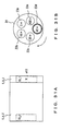
- Fig. 2 is a diagram illustrating an exemplary configuration of the inside of the microscope controller 2 .
- Fig. 3 is a diagram illustrating an example of a portion of the outer package of the microscope controller 2, the portion including a touch panel.
- the microscope controller 2 includes a CPU (Central Processing Unit) 201, a ROM (Read Only Memory) 202, a RAM (Random Access Memory) 203, nonvolatile memory 204, a communication control unit 205, a touch panel control unit 206, and a touch panel 207. Under the management of the CPU 201, these components can give various pieces of data to one another and receive various pieces of data from one another via a bus.
- CPU Central Processing Unit
- ROM Read Only Memory
- RAM Random Access Memory
- the CPU 201 controls the operation of the entirety of the microscope controller 2.
- a control program used by the CPU 201 to control the operation of the microscope controller 2 is stored in advance in the ROM 202.
- Application software for controlling the microscope apparatus 1 is also a portion of this control program.
- the RAM 203 is memory that is used as a work memory area when the CPU 201 executes the control program and that temporarily stores various pieces of data.
- the functional area establishment information is information for establishing, in the display region of the touch panel 207, a plurality of functional areas as regions for making operable each of a plurality of electric units included in the microscope system. Establishing a plurality of functional areas within the display region of the touch panel 207 means that a plurality of regions within the display region of the touch panel 207 is provided and a function for making an electric unit operable is assigned to each of the regions.
- Functions assigned by the functional area establishment information are, for example, a function for making operable an electric unit for moving the electric stage 20 in the XY direction, a function for making operable an electric unit for moving the electric stage 20 in the Z direction, a function for making operable an electric unit for rotating the electric revolver 24 so as to select and insert an optional objective lens into the observation light path, and the like.
- the nonvolatile memory 204 stores at least functional area establishment information for normal functional areas and functional area establishment information for enlarged functional areas.
- the communication control unit 205 manages a data communication (e.g., serial communication) with the microscope control unit 31, and transmits to the microscope control unit 31 control information for controlling the operation of each component unit and the like.
- a data communication e.g., serial communication
- the touch panel 207 has both a function as a display apparatus and a function as an operator for input operations.
- the touchpanel 207 canbe a touchpanel usingamembrane resistance system, a capacitive sensing system, an infrared ray system, an ultrasonic system, or the like.
- the type of the touch panel 207 is not limited.
- the touch panel control unit 206 detects the X coordinate and Y coordinate of the user' s input position on the touch panel 207, and transmits the detected coordinate information to the CPU 201.
- the touch panel 207 is embedded in an outer package 208 of the microscope controller 2. Since the touch panel 207 is embedded in the outer package 208 in such a way that the surface of the touch panel 207 is recessed relative to the surface of the outer package 208, a step 209 serving as a regulation frame is provided between the surface of the touch panel 207 and the surface of the outer package 208.
- the step 209 serving as a regulation frame can prevent the user's finger from accidentally moving outside the touch panel 207.
- the user can also use the step 209 as a guide by moving her/his finger along the step 209. Therefore, the step 209 is effective when, for example, the user operates the touch panel 207 without looking at it.
- the microscope controller 2 has two operation modes, a normal functional area mode and an enlarged functional area mode.
- the normal functional area mode is an operation mode in which, after a plurality of functional areas are established in the display region of the touch panel 207, each of the functional areas remains unchanged (i.e., fixed) .
- the enlarged functional area mode is an operation mode in which, after a plurality of functional areas are established in the display region of the touch panel 207, a plurality of functional areas can be reestablished in the display region of the touch panel 207 so that some of the functional areas are enlarged.
- these two operation modes can be switched via the user operating a switching button (not illustrated) .
- the switching button may be provided virtually in the display region of the touch panel 207 or may be provided physically on the outer package surface of the microscope controller 2.
- Fig. 4 is a diagram illustrating an example of a process flow relating to such an operation above of the microscope controller 2. This process flow is implemented via the CPU 201, which serves as a control unit of the microscope controller 2, reading and executing a control program recorded by the ROM 202.
- Fig. 5 is a diagram illustrating an example of the display screen of the touch panel 207 which is indicated when a plurality of functional areas are established in the display region of the touch panel 207 via the process of S102.
- functional area S_A is a functional area to which a function is assigned for making operable the electric unit for moving the electric stage 20 in the XY direction.
- Functional area S_B is a functional area to which a function is assigned for making operable the electric unit for moving the electric stage 20 in the Z direction.
- Functional area S_C is a functional area to which a function is assigned for making operable the electric revolver 24 for switching the objective lenses 23.
- Functional area S_D is a functional area to which a function is assigned for making operable the electric unit for switching the microscopic examination method.
- Functional area S_E is a functional area to which a function is assigned for enabling the operation for switching the function assigned to functional area S_A.
- Functional area S_F is a functional area to which a function is assigned for making operable other electric units.
- S103 it is determined whether or not there is an input to the touch panel 207, and the process proceeds to S104 if the determination result is Yes (also referred to as "True") and proceeds to S106 if the determination result is No (also referred to as "false") .
- the coordinate of the input position within the touch panel 207 i.e., XY coordinate on the touch panel 207) is obtained, and on the basis of this position and the functional area establishment information read in S101, it is determined which functional area of the touch panel 207 the input corresponds to.
- S105 a control process corresponding to the functional area determined in S104 is performed.
- a control instruction signal corresponding to the operation on the functional area is generated and is transmitted to the microscope control unit 31 by the communication control unit 205, and this will be described later in detail. Then, on the basis of the control instruction signal, the operation of a corresponding electric unit is controlled under the control of the microscope control unit 31.
- the process flow is terminated if the determination result is Yes, and if the determination result is No, the process returns to S103 and the processes S103-S105 are repeated until Yes is indicated in S106.
- the instruction to terminate the observation can be given using, for example, a button provided virtually in the display region of the touch panel 207.
- Fig. 6 is a diagram illustrating an example of a process flow relating to such operations and corresponds to the processes of S104-S106 shown in Fig. 4 .
- Fig. 6 first in S201, it is determined whether or not there is an input to functional area S_A or S_B (also referred to as a "stage area"), and the process proceeds to S202 if the determination result is Yes and proceeds to S106 if the determination result is No.
- S202 the coordinate of the input position within the touch panel 207 (i.e., XY coordinate on the touch panel 207) is detected.
- S203 it is determined whether or not the user is currently performing a drag operation, and the process proceeds to S204 if the determination result is Yes and proceeds to S106 if the determination result is No.
- a drag operation is currently performed if it can be determined that an input is continuously performed on the touch panel 207, and it can be determined that a drag operation is not currently performed if it cannot be determined that an input is continuously performed on the touch panel 207.
- the coordinate of the input position within the touch panel 207 i.e., coordinate corresponding to the drag position (XY coordinate on the touch panel 207)
- the movement distance and movement direction of the electric stage 20 are calculated from the coordinate of the input start position detected in S202 and the coordinate of the drag position detected in S204.
- acontrolinstructionsignal is generated for moving the electric stage 20 in accordance with the calculated movement distance and movement direction, and is transmitted to the microscope control unit 31 via the communicationcontrolunit205. Then, on the basis of the control instruction signal, the microscope control unit 31 controls the stage X-Y drive control unit 21 or stage Z drive control unit 22 so as to drive the X-Y motor 21a or Z motor 22a. In this way, the electric stage 20 is moved in the XY direction or Z direction in accordance with the movement distance and movement direction calculated in S205. After S206, the process returns to S203, and the processes of S203-S206 are repeated until the determination result of S203 is No.
- the microscope controller 2 instructs, via the microscope control unit 31, the stage X-Y drive control unit 21 or stage Z drive control unit 22 to control the electric stage 20 in accordance with the distance and direction of the drag operation.
- the movement distance of the electric stage 20 in the XY direction or Z direction corresponds to the distance of the drag operation on the functional area S_A or S_B.
- the microscope controller 2 instructs the microscope control unit 31 so that the electric stage 20 moves the distance of the drag operation multiplied by a predetermined coefficient, which will be described later.
- Figs. 7 , 8 and 9 are each a diagram illustrating a specific example of an operation that is performed when a user performs a drag operation on functional area S_A in the display screen shown in Fig. 5 .
- Figs. 7A , 8A and 9A illustrate the display screen of the touch panel 207, and their horizontal direction and vertical direction respectively indicate the X direction and Y direction of the touch panel 207.
- Figs. 7B , 8B and 9B schematically illustrate the top surface of the electric stage 20, and their horizontal direction and vertical direction respectively indicate the X direction and Y direction of the electric stage 20.
- the microscope controller 2 instructs, via the microscope control unit 31, the stage X-Y drive control unit 21 to control the electric stage 20 so that it moves to a position corresponding to the distance and direction of the drag operation.
- the movement distance of the electric stage 20 in the XY direction corresponds to the distance of the drag operation on functional area S_A
- the microscope controller 2 instructs the microscope control unit 31 so that the electric stage 20 moves the distance of the drag operation multiplied by coefficient 1a.
- the X direction distance-component of the drag operation is XA and the Y direction distance-component is YA.
- the user's drag operation from the spot a1 to the spot a2 is, for example, an operation performed by touching the spot al with a finger and moving it to the spot a2 without removing it from the touch panel 207. In this case, as illustrated in Figs.
- the electric stage 20 is controlled so that it moves the distance corresponding to XA multiplied by la in the X direction and so that it moves the distance corresponding to YA multiplied by la in the Y direction.
- the electric stage 20 will be controlled via the drag operation so that it further moves to the XY coordinate (X_2, Y_2).
- the value X_2 is XA ⁇ multiplied by 1a with X_1 added to this product.
- the value Y_2 is YA' multiplied by 1a with Y_1 added to this product.
- the electric stage 20 is controlled so that it further moves the distance corresponding to XA ⁇ multiplied by 1a in the X direction and so that it further moves the distance corresponding to YA ⁇ multiplied by 1a in the Y direction.
- Figs. 7-9 for purpose of illustration, examples in which the movement of the electric stage 20 is controlled were described by focusing on the starting spot (e.g., spot a1) and finishing spot (e.g., spot a2) of a drag operation. In fact, however, since the processes of S203-S206 in Fig. 6 are repeated during a drag operation, the electric stage 20 is not controlled to move at a one stroke after the drag operation is finishedbut the movement of the electric stage 20 is controlled so that it continuously follows the drag operation.
- the starting spot e.g., spot a1
- finishing spot e.g., spot a2
- Coefficient 1a used for the movement control of the electric stage 20 via such a drag operation does not need to be fixed but can be variable.
- coefficient 1a can be made variable in accordance with the objective lens 23 to be used.
- Figs. 10 , 11 and 12 are each a diagram illustrating a specific example of an operation that is performed when a user performs a drag operation on functional area S_B in the display screen illustrated in Fig. 5 .
- Figs. 10A , 11A and 12A illustrate the display screen of the touch panel 207, and their horizontal direction and vertical direction respectively indicate the X direction and Y direction of the touch panel 207.
- Figs. 10B , 11B and 12B schematically illustrate the side surface of the electric stage 20, and their vertical direction indicates the Z direction of the electric stage 20.
- a bar 301 in functional area S_B indicates the position of the Z direction coordinate of the electric stage 20. It is indicated that as the bar 301 goes further in the upward direction within functional area S_B, the objective lens 23 and electric stage 20 become closer to each other, and as it goes further in the downward direction, the objective lens 23 and electric stage 20 are further separated from each other.
- the microscope controller 2 gives an instruction to the stage Z drive control unit 22 via the microscope control unit 31 so that the electric stage 20 is controlled to move in a direction in which the objective lens 23 and the electric stage 20 become closer to each other.
- the user's drag operation from the spot b1 to the spot b2 is, for example, an operation performed by touching the spot b1 with a finger and moving it to the spot b2 without removing it from the touch panel 207.
- the microscope controller 2 gives an instruction to the stage Z drive control unit 22 via the microscope control unit 31 so that the electric stage 20 is controlled to move in a direction in which the objective lens 23 and the electric stage 20 are away from each other.
- the user's drag operation from the spot b2 to the spot b1 is, for example, an operation performed by touching the spot b2 with a finger and moving it to the spot b1 without removing it from the touch panel 207.
- the movement distance of the electric stage 20 in the Z direction corresponds to the Y direction distance-component of the drag operation on functional area S_B
- the microscope controller 2 gives an instruction to the microscope control unit 31 so that the electric stage 20 moves in the Z direction the distance corresponding to the distance-component multiplied by coefficient 1b.
- the Y direction distance-component of the drag operation is ZB.
- the electric stage 20 before the drag operation is Z_0 as illustrated in Figs. 10B and 11B
- the electric stage 20 is controlled via the drag operation so that it moves to the Z coordinate Z_1.
- the value Z_1 is ZB multiplied by 1b with Z_0 added to this product.
- the electric stage 20 is controlled so that it moves the distance corresponding to ZB multiplied by 1b in a direction in which the objective lens 23 and the electric stage 20 become closer to each other.
- the bar 301 in functional area S_B moves to the position corresponding to the Z coordinate Z_1, which is upward from the position it was at before the drag operation as illustrated in Fig. 11A .
- the Y direction distance-component of this drag operation is ZB ⁇ .
- the electric stage 20 is controlled via the drag operation so that it further moves to the Z coordinate Z_2.
- the value Z_2 is ZB ⁇ multiplied by 1b with Z_1 added to this product.
- the electric stage 20 is controlled so that it further moves the distance corresponding to ZB ⁇ multiplied by 1b in a direction in which the objective lens 23 and the electric stage 20 become closer to each other.
- the bar 301 in functional area S_B moves to the position corresponding to the Z coordinate Z_2 which is upward from the position it was at before the drag operation, as illustrated in Fig. 12A .
- Figs. 10-12 for purpose of illustration, examples in which the movement of the electric stage 20 is controlled were described by focusing on the starting spot (e.g., spot b1) and finishing spot (e.g., spot b2) of a drag operation. In fact, however, since the processes of S203-S206 in Fig. 6 are repeated during a drag operation, the electric stage 20 is not controlled to move at one stroke after the drag operation is finishedbut the movement of the electric stage 20 is controlled so that it continuously follows the drag operation.
- the starting spot e.g., spot b1
- finishing spot e.g., spot b2
- Coefficient 1b used for the movement control of the electric stage 20 via such a drag operation does not need to be fixed but can be variable.
- coefficient 1b can be made variable in accordance with the objective lens 23 to be used.
- Figs. 13 and 14 are each a diagram illustrating a specific example of an operation that is performed when a user performs an operation on functional area S_C in the display screen illustrated in Fig. 5 .
- Figs. 13A and 14A each illustrate the display screen of the touch panel 207.
- Figs. 13B and 14B each schematically illustrate the switching position of the electric revolver 24 mounted with a plurality of objective lenses 23, and the obj ective lens indicatedusing a thick line is anobj ective lens inserted in the observation light path.
- the electric revolver 24 is mounted with an objective lens 23a with a 5-fold magnification (5x), an objective lens 23b with a 10-fold magnification (10x) , an objective lens 23c with a 20-fold magnification (20x), an objective lens 23d with a 40-fold magnification (40x), and an objective lens 23e with a 100-fold magnification (100x) as a pluralityof objective lenses 23.
- the objective lens 23c with a 20-fold magnification is inserted in the observation light path as illustrated in Fig. 13B .
- corresponding icons 401a-401e are displayed in functional area S_C.
- One of the icons 401a-401e which is displayed to look different from the others indicates the information of an objective lens inserted in the observation light path.
- the icon 401c corresponding to the information of the objective lens 23c is displayed to look different from the others.
- the microscope controller 2 detects the position on the touch panel 207 at which the touchwas released (tobeexact, the position of the touch just before the release of the touch) . Then, the microscope controller 2 gives an instruction to the microscope control unit 31 so that the rotation of the electric revolver 24 is controlled so as to insert, into the observation light path, the objective lens 23d with a 40-fold magnification corresponding to the icon 401d at the detected position. As a result of this, the electric revolver 24 is rotated as illustrated in Fig.
- the icon 401d (instead of the icon 401c) corresponding to the objective lens 23d with a 40-fold magnification inserted in the observation light path is displayed to look different from the others.
- the microscope controller 2 detects the position on the touch panel 207 at which the touch was released (to be exact, the position of the touch just before the release of the touch).
- the microscope controller 2 switches the function assigned to functional area S_A to the function for making operable the electric unit for switching the position of the cube turret 25 or to the function for making operable the electric unit for switching the lighting control quantity of the transmitted illumination light source 6 or the epi-illumination light source 13.
- the icon "Mirror” in functional area S_E is displayed to look different from the other icons as illustrated in Fig. 15 .
- an icon corresponding to the function switched to is displayed in functional area S_A.
- Fig. 16 is a diagram illustrating an example of a process flow relating to the operation above. This process flow is also performed via the CPU 201, which serves as a control unit for the microscope controller 2, recording and executing a control program recorded by the ROM 202.
- Functional area S_D is assigned a function for making operable the electric unit for switchingamicroscopic examinationmethod.
- Functional area S_E is assigned a function for enabling the operation for switching the function assigned to functional area S_A.
- Functional area S_F is assigned a function for making other electric units operable.
- S303 it is determined whether there is an input to the touch panel 207 or not, and the process proceeds to S304 when the determination result is Yes and it proceeds to S307 when the determination result is No.
- the coordinate of the position of the input within the touch panel 207 i.e., the XY coordinate on the touch panel 207 is obtained, and on the basis of this position and the functional area establishment information that was read in S301, it is determined which functional area the input to the touchpanel 207 corresponds to.
- S305 it is determined whether or not the functional area determined in S3 04 is a functional area to be enlarged (i.e., functional area S_A or S_B).
- S305 When the determination result of S305 is No, the process proceeds to S306.
- S306 as with the case of S105 in the process flow under the normal functional area mode (see Fig. 4 ) , a control process is performed in accordance with the functional area determined in S304 (i.e., functional area S C, S D, S_E or S_F) .
- S307 it is determined whether or not an instruction to terminate the observation has been given, and the process flow is terminated when the determination result is Yes and it returns to S303 when the determination result is No.
- Fig. 17 is a diagram illustrating an example of the display screen of the touch panel 207 which is indicated when a plurality of functional areas are reestablished in the display region of the touch panel 207 via the process of S312.
- functional area S_A_2 is a functional area to which a function is assigned for making operable the electric unit for moving the electric stage 20 in the XY direction, and is a functional area that is an enlargement of functional area S_A illustrated in Fig. 5 .
- Functional area S_B_2 is a functional area to which a function is assigned for making operable the electric unit for moving the electric stage 20 in the Z direction, and is a functional area that is an enlargement of functional area S_B illustrated in Fig. 5 .
- a bar 501 in functional area S_B_2 corresponds to the bar 301 in functional area S_B in the display screen illustrated in Fig. 5 .
- S313 it is determined whether or not there is an input to the touch panel 207, and the process proceeds to S314 when the determination result is Yes.
- the coordinate of the position of the input within the touch panel 207 i.e., the XY coordinate on the touch panel 207) is detected, and on the basis of this position and the functional area establishment information that was read in S311, it is determined which functional area the input to the touch panel 207 corresponds to.
- a control process is performed in accordance with the functional area determined in S314. As an example, control is performed to move the electric stage 20 in the XY direction when the input to the display screen illustrated in Fig. 17 corresponds to functional area S_A_2, and control is performed to move the electric stage 20 in the Z direction when the input to the display screen illustrated in Fig. 17 corresponds to functional area S_B_2.
- S315 when the determination result of S313 is No.
- S315 it is determined whether or not no inputs have been performed on the touch panel 207 for a predetermined time period or longer since a plurality of functional areas were reestablished in S312.
- the process returns to S301 when the determination result of S315 is Yes, and the process flow is restarted from the beginning.
- this display screen switching operation can also be performed via, for example, button operations instead of being performed via the determination process of S315.
- the switching button may be provided virtually on the touch panel 207 or may be provided physically on the outer package of the microscope controller 2.
- Figs. 18 are each a diagram illustrating a specific example of an operation that is performed when a user performs a drag operation on functional area S_A_2 in the display screen illustrated in Fig. 17 .
- Fig. 18A illustrates the display screen of the touchpanel 207, and the horizontal direction and vertical direction indicate the X direction and Y direction on the touch panel 207.
- Fig. 18B schematically illustrates the top surface of the electric stage 20, and the horizontal direction and vertical direction indicate the X direction and Y direction of the electric stage 20.
- the X direction distance-component of the drag operation is XA_2 and the Y direction distance-component isYA_2 .
- the user's drag operation from the spot a5 to the spot a6 is, for example, an operation performed by touching the spot a5 with a finger and moving it to the spot a6 without removing it from the touch panel 207. In this case, as illustrated in Fig.
- the electric stage 20 will be controlled via the drag operation so that it moves to the XY coordinate (X_21, Y_21) .
- the value X_21 is XA_2 multiplied by 1a with X_0 added to this product.
- the value Y_21 is YA_2 multiplied by 1a with Y_0 added to this product.
- the electric stage 20 is controlled so that it moves the distance corresponding to XA_2 multiplied by 1a in the X direction and so that it moves the distance corresponding to YA_2 multiplied by 1a in the Y direction.
- Figs. 19 are each a diagram illustrating a specific example of an operation that is performed when a user performs a drag operation on functional area S_B_2 in the display screen illustrated in Fig. 17 .
- Fig. 19A illustrates the display screen of the touch panel 207, and the vertical direction indicates the Y direction on the touch panel 207.
- Fig. 19B schematically illustrates the side surface of the electric stage 20, and the vertical direction indicates the Z direction of the electric stage 20.
- the Y direction distance-component of the drag operation is ZB_2 .
- the user's drag operation from the spot b5 to the spot b6 is, for example, an operation performed by touching the spot b5 with a finger and moving it to the spot b6 without removing it from the touch panel 207.
- the Z coordinate of the electric stage 20 before the drag operation is Z_0, then the electric stage 20 will be controlled via the drag operation so that it moves to the Z coordinate Z_21.
- the value Z_21 is ZB_2 multiplied by 1b with Z_0 added to this product.
- the electric stage 20 is controlled so that it moves the distance corresponding to ZB_2 multiplied by 1b in the direction in which the objective lens 23 and the electric stage 20 become closer to each other.
- the bar 501 in functional area S_B_2 moves to the position corresponding to Z coordinate Z_21, which is upward relative to the position it was at before the drag operation.
- Figs. 20 are each a diagram illustrating a specific example of an operation that is performed when a user performs a drag operation from functional area S_A_2 to functional area S_B_2 in the display screen illustrated in Fig. 17 .
- Fig. 20A illustrates the display screen of the touch panel 207, and the horizontal direction and vertical direction indicate the X direction and Y direction on the touch panel 207.
- Fig. 20B schematically illustrates the top surface of the electric stage 20, and the horizontal direction and vertical direction indicate the X direction and Y direction of the electric stage 20.
- the X direction distance-component of the drag operation is XA_3 and the Y direction distance-component is YA_3.
- the user's drag operation from the spot a7 on functional area S_A_2 to the spot a8 on functional area S_B_S is, for example, an operation performed by touching the spot a7 with a finger and moving it to the spot a8 without removing it from the touch panel 207. In this case, as illustrated in Fig.
- the electric stage 20B if the XY coordinate of the electric stage 20 before the drag operation is (X_0, Y_0) , then the electric stage 20 will be controlled via the drag operation so that it moves to the XY coordinate (X_31, Y 31).
- the value X_31 is XA_3 multiplied by 1a with X_0 added to this product.
- the value Y_31 is YA_3 multiplied by 1a with Y_0 added to this product.
- the electric stage 20 is controlled so that it moves the distance corresponding to XA_3 multiplied by 1a in the X direction and so that it moves the distance corresponding to YA_3 multiplied by 1a in the Y direction.
- the XY direction movement of the electric stage 20 corresponding to functional area S_A_2 on which the drag operation was started is controlled but the Z direction movement of the electric stage 20 is not controlled.
- Figs. 21 are each a diagram illustrating a specific example of an operation that is performed when a user performs a drag operation from functional area S_B_2 to functional area S_A_2 in the display screen illustrated in Fig. 17 .
- Fig. 21A illustrates the display screen of the touch panel 207, and the vertical direction indicates the Y direction on the touch panel 207.
- Fig. 21B schematically illustrates the side surface of the electric stage 20, and the vertical direction indicates the Z direction of the electric stage 20.
- the Y direction distance-component of the drag operation is ZB_3.
- the user's drag operation from the spot b7 on functional area S_B_2 to the spot b8 on functional area S_A_2 is, for example, an operation performed by touching the spot b7 with a finger and moving it to the spot b8 without removing it from the touch panel 207. In this case, as illustrated in Fig.
- the electric stage 20 will be controlled via the drag operation so that it moves to the Z coordinate Z_31.
- the value Z_31 is ZB_3 multiplied by 1b with Z_0 added to this product.
- the electric stage 20 is controlled so that it moves the distance corresponding to ZB_3 multiplied by 1b in the direction in which the objective lens 23 and the electric stage 20 become closer to each other.
- the bar 501 in functional area S_B_2 moves to the position corresponding to Z coordinate Z_31, which is upward relative to the position it was at before the drag operation.
- the Z direction movement of the electric stage 20 corresponding to functional area S_B_2 on which the drag operation was started is controlled but the XY direction movement of the electric stage 20 is not controlled.
- the operations performed when a drag operation is performed from one functional area to another functional area as described using Figs. 20 and 21 can also be performed similarly in the display screen before enlargement of a functional area during the enlarged functional area mode and in the display screen during the normal functional area mode (e.g., the display screen illustrated in Fig. 5 ).
- control is performed in accordance with the functional area in which the drag operation was started.
- the microscope controller 2 has two operation modes, i.e., the normal functional area mode and an enlarged functional area mode; therefore, the size of some functional areas can be varied by switching an operationmode to be used depending on the situation. Therefore, even in a narrow and limited operation area such as a touch panel, the size of a functional area on which a drag operation is performed (i.e., functional areas for moving the electric stage 20 in the XY direction and Z direction) can be enlarged by switching the operation mode to the enlarged functional area mode. Therefore, input can be performed with a longer operation stroke and operations can be performed without looking at the screen, thereby improving the operability.
- the size of some functional areas can be varied by switching an operationmode to be used depending on the situation. Therefore, even in a narrow and limited operation area such as a touch panel, the size of a functional area on which a drag operation is performed (i.e., functional areas for moving the electric stage 20 in the XY direction and Z direction) can be enlarged by switching the operation mode to the enlarged functional area mode.
- the configuration of the microscope system according to the second embodiment of the present invention is different from that of the microscope system according to the first embodiment described above in the sense that the nonvolatile memory 205 of the microscope controller 2 further records, as a table, specific operation information which will be described later. Operations performed by the microscope system according to the second embodiment during the enlarged functional area mode are partly different from those performed by the microscope system according to the first embodiment described above during the enlarged functional area mode. Accordingly, the second embodiment will be described by mainly focusing on the differences. Since the other configurations and operations are the same as those of the microscope system according to the first embodiment, they are not described herein.
- Fig. 23 is a diagram illustrating an example of specific operation information recorded as a table in the nonvolatile memory 204 of the microscope controller 2 according to the present embodiment.
- Figs. 24 and 25 are each a diagram illustrating an example of a plurality of input areas established in advance in the display region of the touch panel 207 of the microscope controller 2.
- specific operation information recorded by the nonvolatile memory 204 defines an ID (identification) , a specific operation associated with the input area, a driven part (electric unit) controlled via the specific operation, a control to be performed for the driven part, and permission/prohibition of the control.
- ID identification
- a specific operation associated with the input area a specific operation associated with the input area
- a driven part electric unit controlled via the specific operation
- a control to be performed for the driven part a control to be performed for the driven part
- permission/prohibition of the control In other words, only the specific operation of an ID for which permission is defined is valid.
- the user can optionally change the combination of an area, a specific operation, a driven part controlled via the specific operation, the control to be performed, and permission/prohibition of the control, and also can optionally define new content.
- the plurality of input areas established in advance in the display area of the touch panel 207 are composed of eleven input areas, i.e., two input areas illustrated in Fig. 24 and nine input areas surrounded by dotted lines illustrated in Fig. 25 .
- the two input areas illustrated in Fig. 24 are input areas corresponding to functional areas S_A_2 and S_B_2.
- the nine input areas illustrated in Fig. 25 are input areas SS_1, SS_2, SS_3 and SS_4 provided along the four sides of the touch panel 207, input areas SS_5, SS_6, SS_7 and SS_8 provided at the four corners of the touch panel 207, and input area SS_9 provided at the center of the touch panel 207.
- driven parts can also be controlled via the specific operations, which are defined by the specific operation information, beingperformedas will be described later in detail.
- Fig. 26 is a diagram illustrating an example of a process flow relating to an operation of the microscope controller 2 which is performed when the operation mode is the enlarged functional area mode in the microscope system according to the second embodiment. This process flow corresponds to the process flow illustrated in Fig. 16 . This process flow is also implemented via the CPU 201, which serves as a control unit of the microscope controller 2, reading and executing a control program recorded by the ROM 202.
- the process flow illustrated in Fig. 26 is the same as the process flow illustrated in Fig. 16 except that the process of S316 illustrated in Fig. 16 is replaced with the processes of S316_1, S316_2 and S316_3. Accordingly, here, these replaced processes are mainly described and the other processes are not described.
- a control process corresponding to the specific operation i.e., control process for a driven part (electric unit) is performed in the following step, S316_3, on the basis of the specific operation information recorded by the nonvolatile memory 204.
- Figs. 27 , 28 and 29 are each a diagram illustrating a specific example of an operation which is performed when a user performs an input in a circular motion within a fixed time period T1 on functional area S_A_2 in the display screen indicated in Fig. 17 ( Fig. 24 ) .
- Figs. 27A , 28A and 29A each show the display screen of the touch panel 207.
- Figs. 27A , 28A and 29A each illustrate the display screen of the touch panel 207.
- Figs. 27B , 28B and 29B each schematically illustrate the switching position of the electric revolver 24 mounted with a plurality of objective lenses 23, and the objective lens indicated using a thick line is the one inserted in the observation light path.
- an objective lens 23a with a 5-fold magnification (5x) , an objective lens 23b with a 10-fold magnification (10x), an objective lens 23c with a 20-foldmagnification (20x) , anobjective lens 23dwitha40-fold magnification (40x) , and an objective lens 23e with a 100-fold magnification (100x) are mounted in the electric revolver 24 as a plurality of objective lenses 23. Also assume that the objective lens 23c with a 20-fold magnification is inserted in the observation light path as illustrated in Fig. 27B .
- Figs. 30 , 31 and 32 are each a diagram illustrating a specific example of an operation which is performed when a user performs input via two touch operations within a fixed time period T2 to the same position in input area SS_1 or SS_2 in the display screen indicated in Fig. 17 ( Fig. 25 ) .
- Figs. 30A , 31A and 32A each illustrate the display screen of the touch panel 207 .
- Figs. 30B , 31B and 32B each schematically illustrate the switching position of the electric revolver 24 mounted with a plurality of objective lenses 23, and the objective lens indicated using a thick line is the one inserted in the observation light path.
- the objective lens 23c with a 20-fold magnification is inserted in the observation light path as illustrated in Fig. 30B .
- Figs. 33 and 34 are each a diagram illustrating a specific example of an operation which is performed when a user performs an input via two touch operations within the fixed time period T2 to the same position in input area SS_3 or SS_4 in the display screen indicated in Fig. 17 ( Fig. 25 ).
- Figs. 33 and 34 each illustrate the display screen of the touch panel 207.
- this input is determined to be an input performed via the specific operation of ID05 defined by the specific operation information illustrated in Fig. 23 .
- an instruction is given to the microscope control unit 31 to control the light source (i.e., the transmitted illumination light source 6 or the epi-illumination light source 13) so that light quantity is increased. As a result of this, the light quantity from the light source increases.
- an input performed via a specific operation is accepted by the display screen (e.g. , the display screen illustrated in Fig. 17 ) after enlargement of a functional area.
- the configuration can also be made such that the display screen before enlargement of a functional area in the enlarged functional area mode and the display screen in the normal functional area mode (e.g., the display screen illustrated in Fig. 5 ) similarly accept an input performed via a specific operation.
- the drag operation when, for example, a drag operation is repeatedly performed as illustrated in Fig. 35 from a spot a17 to a spot a18 on functional area S_B in the display screen in the normal functional area mode, the drag operation may mistakenly deviate to another functional area as illustrated in, for example, Fig. 36 in which a drag operation is performed from a spot a17 ⁇ to a spot a18 ⁇ on functional area S_F.
- an upright microscope apparatus is employed as a microscope apparatus in the microscope system according to each of the embodiments described above, the microscope apparatus to be used is not limited to being upright; therefore, an inverted microscope apparatus can also be employed.
- the present embodiment can also be applied to various systems, such as a line apparatus incorporating a microscope apparatus.
- an objective lens inserted in an observation light path is switched via a revolver with a plurality of objective lenses being rotated.
- an objective lens provided with a zoom function can also be employed.
- a microscope controller having a touch panel is employed.
- the touch panel can be replaced with a device provided with a function equivalent to that of the touch panel.
- the present invention can improve the user operability of a microscope.
Landscapes
- Physics & Mathematics (AREA)
- Chemical & Material Sciences (AREA)
- Analytical Chemistry (AREA)
- General Physics & Mathematics (AREA)
- Optics & Photonics (AREA)
- Engineering & Computer Science (AREA)
- Multimedia (AREA)
- Microscoopes, Condenser (AREA)
- User Interface Of Digital Computer (AREA)
Applications Claiming Priority (1)
| Application Number | Priority Date | Filing Date | Title |
|---|---|---|---|
| JP2009276055A JP5608360B2 (ja) | 2009-12-04 | 2009-12-04 | 顕微鏡コントローラ及び顕微鏡コントローラを備える顕微鏡システム |
Publications (2)
| Publication Number | Publication Date |
|---|---|
| EP2330455A1 true EP2330455A1 (fr) | 2011-06-08 |
| EP2330455B1 EP2330455B1 (fr) | 2019-03-20 |
Family
ID=43734058
Family Applications (1)
| Application Number | Title | Priority Date | Filing Date |
|---|---|---|---|
| EP10015093.7A Active EP2330455B1 (fr) | 2009-12-04 | 2010-11-29 | Contrôleur de microscope et système de microscope doté du contrôleur de microscope |
Country Status (3)
| Country | Link |
|---|---|
| US (1) | US8699131B2 (fr) |
| EP (1) | EP2330455B1 (fr) |
| JP (1) | JP5608360B2 (fr) |
Families Citing this family (16)
| Publication number | Priority date | Publication date | Assignee | Title |
|---|---|---|---|---|
| EP2255730A4 (fr) * | 2008-03-03 | 2014-12-10 | Konica Minolta Inc | Échographe |
| JP5732353B2 (ja) * | 2011-08-31 | 2015-06-10 | 株式会社キーエンス | 拡大観察装置、拡大観察方法および拡大観察プログラム |
| US8922639B2 (en) | 2011-09-27 | 2014-12-30 | Olympus Corporation | Microscope system |
| JP2013072995A (ja) * | 2011-09-27 | 2013-04-22 | Olympus Corp | 顕微鏡システム |
| JP2014002190A (ja) * | 2012-06-15 | 2014-01-09 | Dainippon Printing Co Ltd | コンピュータ装置及びプログラム |
| JP2014026208A (ja) * | 2012-07-30 | 2014-02-06 | Dainippon Printing Co Ltd | コンピュータ装置及びプログラム |
| JP6150586B2 (ja) * | 2013-03-29 | 2017-06-21 | オリンパス株式会社 | 顕微鏡 |
| CN105259649B (zh) * | 2014-07-18 | 2017-03-22 | 承奕科技股份有限公司 | 组合活动式显微镜基座及具有该基座的显微镜 |
| JP5987931B2 (ja) | 2015-02-09 | 2016-09-07 | 株式会社リコー | 映像表示システム、情報処理装置、映像表示方法、映像表示プログラム、映像処理装置、映像処理方法および映像処理プログラム |
| CN105549189A (zh) * | 2015-12-21 | 2016-05-04 | 宁波江丰生物信息技术有限公司 | 一种远程显微镜系统 |
| WO2017160792A1 (fr) * | 2016-03-14 | 2017-09-21 | Endochoice, Inc. | Système et procédé de guidage et de suivi d'une région d'intérêt en utilisant un endoscope |
| JP6630654B2 (ja) * | 2016-11-02 | 2020-01-15 | 株式会社リコー | プログラム、方法、情報処理装置および映像表示システム |
| JP6300974B2 (ja) * | 2017-02-28 | 2018-03-28 | オリンパス株式会社 | 顕微鏡 |
| US10656780B2 (en) | 2018-01-12 | 2020-05-19 | Mitutoyo Corporation | Position specifying method and program |
| DE102018107033A1 (de) * | 2018-03-23 | 2019-09-26 | Leica Microsystems Cms Gmbh | Mikroskopsystem und Verfahren zur Steuerung eines solchen Mikroskopsystems |
| JP6683216B2 (ja) * | 2018-07-03 | 2020-04-15 | 株式会社リコー | プログラム、方法、情報処理装置および映像表示システム |
Citations (7)
| Publication number | Priority date | Publication date | Assignee | Title |
|---|---|---|---|---|
| WO1996018924A1 (fr) | 1994-12-15 | 1996-06-20 | Olympus Optical Co., Ltd. | Microscope pourvu d'organes d'observation et de prise de vues |
| EP1445635A2 (fr) * | 2003-02-07 | 2004-08-11 | Leica Microsystems Wetzlar GmbH | Appareil et programme d'ordinateur pour contrôler les fonctions d'un microscope |
| US20050041282A1 (en) * | 2003-08-21 | 2005-02-24 | Frank Rudolph | Operating menu for a surgical microscope |
| US20080144170A1 (en) * | 2006-12-14 | 2008-06-19 | Olympus Corporation | Microscope system |
| US20080155452A1 (en) * | 2006-12-26 | 2008-06-26 | Olympus Corporation | Microscope device and controller thereof |
| JP2008292578A (ja) | 2007-05-22 | 2008-12-04 | Nikon Corp | 顕微鏡用コントローラと、これを有する顕微鏡装置 |
| EP2108328A1 (fr) * | 2008-04-09 | 2009-10-14 | BrainLAB AG | Procédé de commande basée sur l'image pour appareils médicaux |
Family Cites Families (10)
| Publication number | Priority date | Publication date | Assignee | Title |
|---|---|---|---|---|
| DE69524340T2 (de) * | 1994-09-22 | 2002-08-14 | Aisin Aw Co | Berührungsanzeige für ein Informationseingabesystem |
| JP2000187547A (ja) * | 1998-12-21 | 2000-07-04 | Canon Inc | スクロール制御装置および方法 |
| JP2002281365A (ja) * | 2001-03-16 | 2002-09-27 | Ricoh Co Ltd | デジタルカメラ |
| JP2002351618A (ja) * | 2001-05-29 | 2002-12-06 | Matsushita Electric Ind Co Ltd | 機能選択方法およびそれを用いた光ディスク再生装置 |
| JP2005331889A (ja) * | 2004-05-21 | 2005-12-02 | Keyence Corp | 蛍光顕微鏡及び蛍光観察方法 |
| JP4210936B2 (ja) * | 2004-07-08 | 2009-01-21 | ソニー株式会社 | 情報処理装置及びこれに用いるプログラム |
| US7362221B2 (en) * | 2005-11-09 | 2008-04-22 | Honeywell International Inc. | Touchscreen device for controlling a security system |
| JP4244068B1 (ja) * | 2008-08-21 | 2009-03-25 | 任天堂株式会社 | オブジェクト表示順変更プログラム及び装置 |
| US8276093B2 (en) * | 2008-04-24 | 2012-09-25 | Nintendo Co., Ltd. | Computer-readable storage medium having object display order changing program stored therein and apparatus |
| JP4171770B1 (ja) * | 2008-04-24 | 2008-10-29 | 任天堂株式会社 | オブジェクト表示順変更プログラム及び装置 |
-
2009
- 2009-12-04 JP JP2009276055A patent/JP5608360B2/ja active Active
-
2010
- 2010-11-29 EP EP10015093.7A patent/EP2330455B1/fr active Active
- 2010-11-30 US US12/956,537 patent/US8699131B2/en active Active
Patent Citations (7)
| Publication number | Priority date | Publication date | Assignee | Title |
|---|---|---|---|---|
| WO1996018924A1 (fr) | 1994-12-15 | 1996-06-20 | Olympus Optical Co., Ltd. | Microscope pourvu d'organes d'observation et de prise de vues |
| EP1445635A2 (fr) * | 2003-02-07 | 2004-08-11 | Leica Microsystems Wetzlar GmbH | Appareil et programme d'ordinateur pour contrôler les fonctions d'un microscope |
| US20050041282A1 (en) * | 2003-08-21 | 2005-02-24 | Frank Rudolph | Operating menu for a surgical microscope |
| US20080144170A1 (en) * | 2006-12-14 | 2008-06-19 | Olympus Corporation | Microscope system |
| US20080155452A1 (en) * | 2006-12-26 | 2008-06-26 | Olympus Corporation | Microscope device and controller thereof |
| JP2008292578A (ja) | 2007-05-22 | 2008-12-04 | Nikon Corp | 顕微鏡用コントローラと、これを有する顕微鏡装置 |
| EP2108328A1 (fr) * | 2008-04-09 | 2009-10-14 | BrainLAB AG | Procédé de commande basée sur l'image pour appareils médicaux |
Also Published As
| Publication number | Publication date |
|---|---|
| EP2330455B1 (fr) | 2019-03-20 |
| JP5608360B2 (ja) | 2014-10-15 |
| US8699131B2 (en) | 2014-04-15 |
| JP2011118188A (ja) | 2011-06-16 |
| US20110134517A1 (en) | 2011-06-09 |
Similar Documents
| Publication | Publication Date | Title |
|---|---|---|
| EP2330455B1 (fr) | Contrôleur de microscope et système de microscope doté du contrôleur de microscope | |
| US8466958B2 (en) | Microscope system that is capable of electrically changing an observation state of a sample | |
| US8867126B2 (en) | Microscope controller and microscope system having microscope controller | |
| US20230355323A1 (en) | Surgical microscope with gesture control and method for a gesture control of a surgical microscope | |
| JP5468892B2 (ja) | 顕微鏡コントローラ及び顕微鏡コントローラを備える顕微鏡システム | |
| JP4267030B2 (ja) | 顕微鏡装置、コントローラ、及びプログラム | |
| US8649088B2 (en) | Microscope system | |
| JP5649851B2 (ja) | 顕微鏡コントローラを有する顕微鏡システム | |
| WO2022084240A1 (fr) | Système pour un systeme de microscope, procédé et programme informatique correspondants | |
| US20230195295A1 (en) | Microscope control arrangement | |
| US10473909B2 (en) | Microscope system having touch panel and electronic stage driving amount based on pressure detection | |
| JP5965966B2 (ja) | 顕微鏡コントローラ及び該顕微鏡コントローラを有する顕微鏡システム | |
| JP5911535B2 (ja) | 顕微鏡コントローラを備える顕微鏡システム | |
| JP5649848B2 (ja) | 顕微鏡コントローラ及び該顕微鏡コントローラを有する顕微鏡システム | |
| WO2020146037A1 (fr) | Machine de microdissection par capture laser à réalité augmentée | |
| JP2002040334A (ja) | 顕微鏡制御装置、顕微鏡制御装置の使用方法、顕微鏡装置の制御方法 | |
| JP4374893B2 (ja) | 焦準装置及びこれを備えた顕微鏡 | |
| JP2006023487A (ja) | 顕微鏡装置 |
Legal Events
| Date | Code | Title | Description |
|---|---|---|---|
| PUAI | Public reference made under article 153(3) epc to a published international application that has entered the european phase |
Free format text: ORIGINAL CODE: 0009012 |
|
| AK | Designated contracting states |
Kind code of ref document: A1 Designated state(s): AL AT BE BG CH CY CZ DE DK EE ES FI FR GB GR HR HU IE IS IT LI LT LU LV MC MK MT NL NO PL PT RO RS SE SI SK SM TR |
|
| AX | Request for extension of the european patent |
Extension state: BA ME |
|
| 17P | Request for examination filed |
Effective date: 20111118 |
|
| RAP1 | Party data changed (applicant data changed or rights of an application transferred) |
Owner name: OLYMPUS CORPORATION |
|
| RAP1 | Party data changed (applicant data changed or rights of an application transferred) |
Owner name: OLYMPUS CORPORATION |
|
| RIN1 | Information on inventor provided before grant (corrected) |
Inventor name: SHIROTA, TETSUYA Inventor name: SUKEKAWA, MINORU Inventor name: YAMAGUCHI, KATSUYOSHI |
|
| STAA | Information on the status of an ep patent application or granted ep patent |
Free format text: STATUS: EXAMINATION IS IN PROGRESS |
|
| 17Q | First examination report despatched |
Effective date: 20170224 |
|
| GRAP | Despatch of communication of intention to grant a patent |
Free format text: ORIGINAL CODE: EPIDOSNIGR1 |
|
| STAA | Information on the status of an ep patent application or granted ep patent |
Free format text: STATUS: GRANT OF PATENT IS INTENDED |
|
| INTG | Intention to grant announced |
Effective date: 20181011 |
|
| GRAS | Grant fee paid |
Free format text: ORIGINAL CODE: EPIDOSNIGR3 |
|
| GRAA | (expected) grant |
Free format text: ORIGINAL CODE: 0009210 |
|
| STAA | Information on the status of an ep patent application or granted ep patent |
Free format text: STATUS: THE PATENT HAS BEEN GRANTED |
|
| AK | Designated contracting states |
Kind code of ref document: B1 Designated state(s): AL AT BE BG CH CY CZ DE DK EE ES FI FR GB GR HR HU IE IS IT LI LT LU LV MC MK MT NL NO PL PT RO RS SE SI SK SM TR |
|
| REG | Reference to a national code |
Ref country code: GB Ref legal event code: FG4D |
|
| REG | Reference to a national code |
Ref country code: CH Ref legal event code: EP |
|
| REG | Reference to a national code |
Ref country code: DE Ref legal event code: R096 Ref document number: 602010057648 Country of ref document: DE |
|
| REG | Reference to a national code |
Ref country code: AT Ref legal event code: REF Ref document number: 1111115 Country of ref document: AT Kind code of ref document: T Effective date: 20190415 |
|
| REG | Reference to a national code |
Ref country code: IE Ref legal event code: FG4D |
|
| REG | Reference to a national code |
Ref country code: NL Ref legal event code: MP Effective date: 20190320 |
|
| PG25 | Lapsed in a contracting state [announced via postgrant information from national office to epo] |
Ref country code: SE Free format text: LAPSE BECAUSE OF FAILURE TO SUBMIT A TRANSLATION OF THE DESCRIPTION OR TO PAY THE FEE WITHIN THE PRESCRIBED TIME-LIMIT Effective date: 20190320 Ref country code: LT Free format text: LAPSE BECAUSE OF FAILURE TO SUBMIT A TRANSLATION OF THE DESCRIPTION OR TO PAY THE FEE WITHIN THE PRESCRIBED TIME-LIMIT Effective date: 20190320 Ref country code: NO Free format text: LAPSE BECAUSE OF FAILURE TO SUBMIT A TRANSLATION OF THE DESCRIPTION OR TO PAY THE FEE WITHIN THE PRESCRIBED TIME-LIMIT Effective date: 20190620 Ref country code: FI Free format text: LAPSE BECAUSE OF FAILURE TO SUBMIT A TRANSLATION OF THE DESCRIPTION OR TO PAY THE FEE WITHIN THE PRESCRIBED TIME-LIMIT Effective date: 20190320 |
|
| REG | Reference to a national code |
Ref country code: LT Ref legal event code: MG4D |
|
| PG25 | Lapsed in a contracting state [announced via postgrant information from national office to epo] |
Ref country code: BG Free format text: LAPSE BECAUSE OF FAILURE TO SUBMIT A TRANSLATION OF THE DESCRIPTION OR TO PAY THE FEE WITHIN THE PRESCRIBED TIME-LIMIT Effective date: 20190620 Ref country code: RS Free format text: LAPSE BECAUSE OF FAILURE TO SUBMIT A TRANSLATION OF THE DESCRIPTION OR TO PAY THE FEE WITHIN THE PRESCRIBED TIME-LIMIT Effective date: 20190320 Ref country code: HR Free format text: LAPSE BECAUSE OF FAILURE TO SUBMIT A TRANSLATION OF THE DESCRIPTION OR TO PAY THE FEE WITHIN THE PRESCRIBED TIME-LIMIT Effective date: 20190320 Ref country code: LV Free format text: LAPSE BECAUSE OF FAILURE TO SUBMIT A TRANSLATION OF THE DESCRIPTION OR TO PAY THE FEE WITHIN THE PRESCRIBED TIME-LIMIT Effective date: 20190320 Ref country code: NL Free format text: LAPSE BECAUSE OF FAILURE TO SUBMIT A TRANSLATION OF THE DESCRIPTION OR TO PAY THE FEE WITHIN THE PRESCRIBED TIME-LIMIT Effective date: 20190320 Ref country code: GR Free format text: LAPSE BECAUSE OF FAILURE TO SUBMIT A TRANSLATION OF THE DESCRIPTION OR TO PAY THE FEE WITHIN THE PRESCRIBED TIME-LIMIT Effective date: 20190621 |
|
| REG | Reference to a national code |
Ref country code: AT Ref legal event code: MK05 Ref document number: 1111115 Country of ref document: AT Kind code of ref document: T Effective date: 20190320 |
|
| PG25 | Lapsed in a contracting state [announced via postgrant information from national office to epo] |
Ref country code: ES Free format text: LAPSE BECAUSE OF FAILURE TO SUBMIT A TRANSLATION OF THE DESCRIPTION OR TO PAY THE FEE WITHIN THE PRESCRIBED TIME-LIMIT Effective date: 20190320 Ref country code: AL Free format text: LAPSE BECAUSE OF FAILURE TO SUBMIT A TRANSLATION OF THE DESCRIPTION OR TO PAY THE FEE WITHIN THE PRESCRIBED TIME-LIMIT Effective date: 20190320 Ref country code: SK Free format text: LAPSE BECAUSE OF FAILURE TO SUBMIT A TRANSLATION OF THE DESCRIPTION OR TO PAY THE FEE WITHIN THE PRESCRIBED TIME-LIMIT Effective date: 20190320 Ref country code: PT Free format text: LAPSE BECAUSE OF FAILURE TO SUBMIT A TRANSLATION OF THE DESCRIPTION OR TO PAY THE FEE WITHIN THE PRESCRIBED TIME-LIMIT Effective date: 20190720 Ref country code: EE Free format text: LAPSE BECAUSE OF FAILURE TO SUBMIT A TRANSLATION OF THE DESCRIPTION OR TO PAY THE FEE WITHIN THE PRESCRIBED TIME-LIMIT Effective date: 20190320 Ref country code: RO Free format text: LAPSE BECAUSE OF FAILURE TO SUBMIT A TRANSLATION OF THE DESCRIPTION OR TO PAY THE FEE WITHIN THE PRESCRIBED TIME-LIMIT Effective date: 20190320 Ref country code: IT Free format text: LAPSE BECAUSE OF FAILURE TO SUBMIT A TRANSLATION OF THE DESCRIPTION OR TO PAY THE FEE WITHIN THE PRESCRIBED TIME-LIMIT Effective date: 20190320 Ref country code: CZ Free format text: LAPSE BECAUSE OF FAILURE TO SUBMIT A TRANSLATION OF THE DESCRIPTION OR TO PAY THE FEE WITHIN THE PRESCRIBED TIME-LIMIT Effective date: 20190320 |
|
| PG25 | Lapsed in a contracting state [announced via postgrant information from national office to epo] |
Ref country code: SM Free format text: LAPSE BECAUSE OF FAILURE TO SUBMIT A TRANSLATION OF THE DESCRIPTION OR TO PAY THE FEE WITHIN THE PRESCRIBED TIME-LIMIT Effective date: 20190320 Ref country code: PL Free format text: LAPSE BECAUSE OF FAILURE TO SUBMIT A TRANSLATION OF THE DESCRIPTION OR TO PAY THE FEE WITHIN THE PRESCRIBED TIME-LIMIT Effective date: 20190320 |
|
| PG25 | Lapsed in a contracting state [announced via postgrant information from national office to epo] |
Ref country code: IS Free format text: LAPSE BECAUSE OF FAILURE TO SUBMIT A TRANSLATION OF THE DESCRIPTION OR TO PAY THE FEE WITHIN THE PRESCRIBED TIME-LIMIT Effective date: 20190720 Ref country code: AT Free format text: LAPSE BECAUSE OF FAILURE TO SUBMIT A TRANSLATION OF THE DESCRIPTION OR TO PAY THE FEE WITHIN THE PRESCRIBED TIME-LIMIT Effective date: 20190320 |
|
| REG | Reference to a national code |
Ref country code: DE Ref legal event code: R097 Ref document number: 602010057648 Country of ref document: DE |
|
| PLBE | No opposition filed within time limit |
Free format text: ORIGINAL CODE: 0009261 |
|
| STAA | Information on the status of an ep patent application or granted ep patent |
Free format text: STATUS: NO OPPOSITION FILED WITHIN TIME LIMIT |
|
| PG25 | Lapsed in a contracting state [announced via postgrant information from national office to epo] |
Ref country code: DK Free format text: LAPSE BECAUSE OF FAILURE TO SUBMIT A TRANSLATION OF THE DESCRIPTION OR TO PAY THE FEE WITHIN THE PRESCRIBED TIME-LIMIT Effective date: 20190320 |
|
| 26N | No opposition filed |
Effective date: 20200102 |
|
| PG25 | Lapsed in a contracting state [announced via postgrant information from national office to epo] |
Ref country code: SI Free format text: LAPSE BECAUSE OF FAILURE TO SUBMIT A TRANSLATION OF THE DESCRIPTION OR TO PAY THE FEE WITHIN THE PRESCRIBED TIME-LIMIT Effective date: 20190320 |
|
| PG25 | Lapsed in a contracting state [announced via postgrant information from national office to epo] |
Ref country code: TR Free format text: LAPSE BECAUSE OF FAILURE TO SUBMIT A TRANSLATION OF THE DESCRIPTION OR TO PAY THE FEE WITHIN THE PRESCRIBED TIME-LIMIT Effective date: 20190320 |
|
| REG | Reference to a national code |
Ref country code: CH Ref legal event code: PL |
|
| PG25 | Lapsed in a contracting state [announced via postgrant information from national office to epo] |
Ref country code: LI Free format text: LAPSE BECAUSE OF NON-PAYMENT OF DUE FEES Effective date: 20191130 Ref country code: CH Free format text: LAPSE BECAUSE OF NON-PAYMENT OF DUE FEES Effective date: 20191130 Ref country code: MC Free format text: LAPSE BECAUSE OF FAILURE TO SUBMIT A TRANSLATION OF THE DESCRIPTION OR TO PAY THE FEE WITHIN THE PRESCRIBED TIME-LIMIT Effective date: 20190320 Ref country code: LU Free format text: LAPSE BECAUSE OF NON-PAYMENT OF DUE FEES Effective date: 20191129 |
|
| REG | Reference to a national code |
Ref country code: BE Ref legal event code: MM Effective date: 20191130 |
|
| GBPC | Gb: european patent ceased through non-payment of renewal fee |
Effective date: 20191129 |
|
| PG25 | Lapsed in a contracting state [announced via postgrant information from national office to epo] |
Ref country code: GB Free format text: LAPSE BECAUSE OF NON-PAYMENT OF DUE FEES Effective date: 20191129 Ref country code: IE Free format text: LAPSE BECAUSE OF NON-PAYMENT OF DUE FEES Effective date: 20191129 |
|
| PG25 | Lapsed in a contracting state [announced via postgrant information from national office to epo] |
Ref country code: BE Free format text: LAPSE BECAUSE OF NON-PAYMENT OF DUE FEES Effective date: 20191130 |
|
| PG25 | Lapsed in a contracting state [announced via postgrant information from national office to epo] |
Ref country code: CY Free format text: LAPSE BECAUSE OF FAILURE TO SUBMIT A TRANSLATION OF THE DESCRIPTION OR TO PAY THE FEE WITHIN THE PRESCRIBED TIME-LIMIT Effective date: 20190320 |
|
| PG25 | Lapsed in a contracting state [announced via postgrant information from national office to epo] |
Ref country code: MT Free format text: LAPSE BECAUSE OF FAILURE TO SUBMIT A TRANSLATION OF THE DESCRIPTION OR TO PAY THE FEE WITHIN THE PRESCRIBED TIME-LIMIT Effective date: 20190320 Ref country code: HU Free format text: LAPSE BECAUSE OF FAILURE TO SUBMIT A TRANSLATION OF THE DESCRIPTION OR TO PAY THE FEE WITHIN THE PRESCRIBED TIME-LIMIT; INVALID AB INITIO Effective date: 20101129 Ref country code: FR Free format text: LAPSE BECAUSE OF NON-PAYMENT OF DUE FEES Effective date: 20191202 |
|
| PG25 | Lapsed in a contracting state [announced via postgrant information from national office to epo] |
Ref country code: MK Free format text: LAPSE BECAUSE OF FAILURE TO SUBMIT A TRANSLATION OF THE DESCRIPTION OR TO PAY THE FEE WITHIN THE PRESCRIBED TIME-LIMIT Effective date: 20190320 |
|
| REG | Reference to a national code |
Ref country code: DE Ref legal event code: R081 Ref document number: 602010057648 Country of ref document: DE Owner name: EVIDENT CORPORATION, JP Free format text: FORMER OWNER: OLYMPUS CORPORATION, TOKIO/TOKYO, JP |
|
| PGFP | Annual fee paid to national office [announced via postgrant information from national office to epo] |
Ref country code: DE Payment date: 20231121 Year of fee payment: 14 |