EP2330377A2 - Schutzmodul mit schüttgutförmigem Material - Google Patents
Schutzmodul mit schüttgutförmigem Material Download PDFInfo
- Publication number
- EP2330377A2 EP2330377A2 EP10193240A EP10193240A EP2330377A2 EP 2330377 A2 EP2330377 A2 EP 2330377A2 EP 10193240 A EP10193240 A EP 10193240A EP 10193240 A EP10193240 A EP 10193240A EP 2330377 A2 EP2330377 A2 EP 2330377A2
- Authority
- EP
- European Patent Office
- Prior art keywords
- bulk material
- individual elements
- elements
- individual
- material according
- Prior art date
- Legal status (The legal status is an assumption and is not a legal conclusion. Google has not performed a legal analysis and makes no representation as to the accuracy of the status listed.)
- Granted
Links
- 239000013590 bulk material Substances 0.000 title claims description 47
- 239000000463 material Substances 0.000 claims abstract description 25
- 230000001681 protective effect Effects 0.000 claims abstract description 8
- 229910000639 Spring steel Inorganic materials 0.000 claims abstract description 6
- 229920002635 polyurethane Polymers 0.000 claims abstract description 5
- 239000004814 polyurethane Substances 0.000 claims abstract description 5
- 239000007769 metal material Substances 0.000 claims abstract description 4
- 229910010293 ceramic material Inorganic materials 0.000 claims abstract description 3
- 239000004033 plastic Substances 0.000 claims abstract description 3
- 229920003023 plastic Polymers 0.000 claims abstract description 3
- 239000010410 layer Substances 0.000 claims description 7
- 239000012790 adhesive layer Substances 0.000 claims description 5
- 239000007788 liquid Substances 0.000 claims description 5
- 230000001070 adhesive effect Effects 0.000 claims description 3
- 150000001875 compounds Chemical class 0.000 claims description 2
- 230000035939 shock Effects 0.000 abstract description 2
- 238000013016 damping Methods 0.000 description 4
- 230000000694 effects Effects 0.000 description 3
- 229920001971 elastomer Polymers 0.000 description 3
- 239000000806 elastomer Substances 0.000 description 2
- 238000004519 manufacturing process Methods 0.000 description 2
- 239000011159 matrix material Substances 0.000 description 2
- 239000000203 mixture Substances 0.000 description 2
- 239000007787 solid Substances 0.000 description 2
- PNEYBMLMFCGWSK-UHFFFAOYSA-N Alumina Chemical compound [O-2].[O-2].[O-2].[Al+3].[Al+3] PNEYBMLMFCGWSK-UHFFFAOYSA-N 0.000 description 1
- 235000002595 Solanum tuberosum Nutrition 0.000 description 1
- 244000061456 Solanum tuberosum Species 0.000 description 1
- 238000010521 absorption reaction Methods 0.000 description 1
- 239000000853 adhesive Substances 0.000 description 1
- 239000002131 composite material Substances 0.000 description 1
- 230000006378 damage Effects 0.000 description 1
- 230000001419 dependent effect Effects 0.000 description 1
- 238000011161 development Methods 0.000 description 1
- 230000018109 developmental process Effects 0.000 description 1
- 239000003822 epoxy resin Substances 0.000 description 1
- 239000012530 fluid Substances 0.000 description 1
- 239000000446 fuel Substances 0.000 description 1
- LNEPOXFFQSENCJ-UHFFFAOYSA-N haloperidol Chemical compound C1CC(O)(C=2C=CC(Cl)=CC=2)CCN1CCCC(=O)C1=CC=C(F)C=C1 LNEPOXFFQSENCJ-UHFFFAOYSA-N 0.000 description 1
- 239000006262 metallic foam Substances 0.000 description 1
- 238000004806 packaging method and process Methods 0.000 description 1
- 229920000647 polyepoxide Polymers 0.000 description 1
- 229920000728 polyester Polymers 0.000 description 1
- 229920001296 polysiloxane Polymers 0.000 description 1
- 238000004382 potting Methods 0.000 description 1
- 238000004073 vulcanization Methods 0.000 description 1
Images



Classifications
-
- F—MECHANICAL ENGINEERING; LIGHTING; HEATING; WEAPONS; BLASTING
- F41—WEAPONS
- F41H—ARMOUR; ARMOURED TURRETS; ARMOURED OR ARMED VEHICLES; MEANS OF ATTACK OR DEFENCE, e.g. CAMOUFLAGE, IN GENERAL
- F41H7/00—Armoured or armed vehicles
- F41H7/02—Land vehicles with enclosing armour, e.g. tanks
- F41H7/04—Armour construction
-
- F—MECHANICAL ENGINEERING; LIGHTING; HEATING; WEAPONS; BLASTING
- F41—WEAPONS
- F41H—ARMOUR; ARMOURED TURRETS; ARMOURED OR ARMED VEHICLES; MEANS OF ATTACK OR DEFENCE, e.g. CAMOUFLAGE, IN GENERAL
- F41H5/00—Armour; Armour plates
- F41H5/013—Mounting or securing armour plates
-
- F—MECHANICAL ENGINEERING; LIGHTING; HEATING; WEAPONS; BLASTING
- F41—WEAPONS
- F41H—ARMOUR; ARMOURED TURRETS; ARMOURED OR ARMED VEHICLES; MEANS OF ATTACK OR DEFENCE, e.g. CAMOUFLAGE, IN GENERAL
- F41H5/00—Armour; Armour plates
- F41H5/02—Plate construction
- F41H5/04—Plate construction composed of more than one layer
-
- F—MECHANICAL ENGINEERING; LIGHTING; HEATING; WEAPONS; BLASTING
- F41—WEAPONS
- F41H—ARMOUR; ARMOURED TURRETS; ARMOURED OR ARMED VEHICLES; MEANS OF ATTACK OR DEFENCE, e.g. CAMOUFLAGE, IN GENERAL
- F41H5/00—Armour; Armour plates
- F41H5/02—Plate construction
- F41H5/04—Plate construction composed of more than one layer
- F41H5/0492—Layered armour containing hard elements, e.g. plates, spheres, rods, separated from each other, the elements being connected to a further flexible layer or being embedded in a plastics or an elastomer matrix
Definitions
- the invention relates to a bulk material consisting of a plurality of shock-absorbing individual elements as well as a protective module containing such a material for protecting vehicles and objects against military threats.
- Such a protection module is for example in DE 10 257 942 A1 described. It consists of a material or contains a material that is designed as a three-dimensional metallic grid structure or open-cell metal foam.
- a composite armor plate for the protection of vehicles or buildings from armor-piercing projectiles with high kinetic energy is z.
- It contains at least one layer of high-hardness, for example made of alumina ceramic elements, which are arranged within a matrix of a potting compound.
- the invention has for its object to provide a protection of vehicles and objects against military threats, for example, shaped charges, mines or impact missiles, which is inexpensive to manufacture and can be easily adapted to more complicated structures on or in vehicles or buildings ,
- the invention is based on a bulk material which consists of a plurality of shock-absorbing individual elements.
- the damping properties of bulk material are known in principle and are used, for example, in packaging for the protection of sensitive objects or devices during transport.
- a basic idea of the invention is that a material in the form of a bulk material can be used as a protective material on vehicles and objects for protection against military threats, in particular by shaped charges, mines or impact projectiles, since it easily becomes more complicated due to its flexibility as bulk material can be adjusted.
- each individual element can have very different spatial structures.
- each individual element may comprise at least two interconnected, substantially as thin, flat plates formed sub-elements, wherein each at least two of these plates are in different, intersecting in the region of the junction of the plates planes.
- the planes can intersect at an angle of up to 90 °, in particular up to 60 °, preferably up to 45 °.
- each individual element has at least one partial element which is connected to other partial elements and is designed as a substantially thin, curved strip.
- the sub-elements are preferably integrally and materially connected to each other.
- each individual element is designed as substantially thinner, at least in partial regions of curved strips.
- the individual elements may be chip-shaped in a manner known per se.
- the individual elements may have an open hollow structure.
- the individual elements are thus not as a solid body, such as a solid ball, designed, but only as a hollow body.
- the hollow body in turn does not have to be closed, such as a hollow sphere, but he can to one or more sides open, such as half a hollow ball.
- an advantageous weight of the individual elements is achieved with good damping properties.
- Due to the open hollow structure it is possible that the individual elements interlock. Preferably, they have a serrated end portion, so that an improved positional security when meshing can be achieved.
- the bulk material may also consist of a mixture of individual elements with different spatial structure.
- the individual elements are so asymmetrically constructed that they are not stackable. This effect can also be achieved by widely spread tolerances (tolerance overlaps) of identical individual elements. In this way, settling phenomena caused by vibration are avoided in the bed, and the material retains a high proportion of air volume with low overall weight.
- the individual elements or at least a subset of the individual elements in the bulk material has at least one resiliently formed part element.
- the individual elements may consist of a metallic material, for example of spring steel. But it is also possible to form the individual elements of a ceramic material or a plastic material. Furthermore, the individual elements can also consist of an irreversibly deformable material or of a material with a defined brittleness. In brittle materials, the damping effect is achieved by the energy-consuming "break work" in the destruction of the individual elements.
- the aim of all these training is that the bulk material in the poured state between the individual elements has a high intermediate volume and has good overall shock-absorbing properties.
- the individual elements of the bulk material are coated on its surface with a material having a predetermined adhesive effect, so that after the bed, the resulting overall structure of the material is fixed.
- the elements each consist of at least two identically shaped individual elements, which are sandwiched and interconnected with the interposition of a connecting layer, in particular an adhesive layer.
- a connecting layer in particular an adhesive layer.
- each element may be composed of two individual elements made of a KTL-coated spring steel sheet with an adhesive layer of polyurethane disposed therebetween.
- the bonding layer may have damping properties.
- the bond can also be made with other inorganic or organic adhesives, so for example epoxy resins, polyesters or silicones.
- epoxy resins for example epoxy resins, polyesters or silicones.
- elastomers by means of which the elements can be connected to one another by vulcanization.
- this is introduced into cavities present on or in the vehicle or object, in particular in a liquid tank, of a vehicle.
- the application of the bulk material as a protective material against military threat can be done in such a way that it is poured directly into cavities or depressions on the outside of a vehicle or other object.
- a protection module having a housing into which the bulk material can be poured. This housing can be closed with a cover.
- the bulk material may also be arranged in a plurality of separate layers by gaps. If the bulk material consists of resiliently formed individual elements, it may also be advantageous if it is set in the housing, for example by placing a cover under a predetermined bias.
- the bulk material according to the invention can be incorporated not only in cavities on the outside of a vehicle or object, but also in cavities located inside a vehicle or object.
- it can be introduced into a liquid tank of a vehicle, for example into a niche tank of a battle tank, as a result of which the tank acquires greater stability and at the same time acts as a protection module.
- these cavities in tanks usually made of elastomers (rubber) the bed also acts as a support body with emptied or pronouncedtleertem tank.
- the introduced elements in vehicle tanks counteract rapid fluid movements (anti-swirling) while driving.
- it may be advantageous if the individual elements of the bulk material are connected to each other in the tank by point bonding and thus form a stable matrix.
- the bulk material is therefore also suitable as a retrofit solution to increase the protection.
- FIG. 1 shows an open housing 1 in which a bulk material 2 is introduced, consisting of individual elements of different spatial structure consists.
- the individual elements of the bulk material 2 are preferably formed and the mixture is such that no stacking effects occur as possible.
- the housing 1 can be closed in a manner not shown by a cover and the resulting protection module can be arranged in a manner not shown on a vehicle or building.
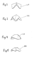
- the FIGS. 2 to 5 show possible individual elements 2.1, 2.2, 2.3 and 2.4 of the bulk material, which may be formed for example of spring steel. However, other metallic or non-metallic materials are also conceivable here.
- FIGS. 2 to 5 illustrated structures of the individual elements 2.1 - 2.4 are merely examples, there are also other structures possible, in particular structures in which the individual elements contain curved trained sub-elements or constructed entirely of curved sub-elements. They may for example also be formed potato chip.
- the illustrated individual elements 2.1 - 2.4 have a hollow structure with serrated end sections.
- the hollow structure is not closed but open. This results in a bowl-shaped configuration.
- FIG. 6 shows a part of a main battle tank KP with a vehicle housing 4, which is constructed on a tracked chassis 3, above the chains are arranged in the chain guard 5 niche tank 6.1 and 6.2 for receiving a liquid fuel.
- the in FIGS. 7 to 9 illustrated niche tank 6.1 with a filling opening 6.11 and 6.12 and 6.13 connecting piece is filled with a bulk material 7, which in the FIGS. 7 and 9 schematically indicated as crosshatching. In this way, a gain of the ballistic protection is achieved by the niche tanks 6.1 and 6.2.
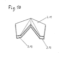
- FIG. 10 shows the structure of an element sandwiched from two individual elements according to FIG. 2 is constructed.
- the two individual elements 2.11 and 2.12 are arranged one above the other and connected to each other via an adhesive layer 2.13 made of polyurethane.
- the individual elements 2.11 and 2.12 consist of KTL-coated spring steel sheet.
- the thickness of the individual elements may be, for example, 1 mm, while the thickness of the polyurethane adhesive layer may be 3 mm, for example.
Landscapes
- Engineering & Computer Science (AREA)
- General Engineering & Computer Science (AREA)
- Laminated Bodies (AREA)
- Aiming, Guidance, Guns With A Light Source, Armor, Camouflage, And Targets (AREA)
- Vibration Dampers (AREA)
Abstract
Description
- Die Erfindung betrifft ein aus einer Vielzahl von schockdämpfenden Einzelelementen bestehendes schüttgutförmiges Material sowie ein derartiges Material enthaltendes Schutzmodul zum Schutz von Fahrzeugen und Objekten gegen militärische Bedrohungen.
- Es ist bekannt, Fahrzeuge und Objekte gegen militärische Bedrohungen, beispielsweise Hohlladungen, Minen oder Impact-Geschosse durch Schutzmodule und Panzerplatten zu schützen.
- Ein derartiges Schutzmodul ist zum Beispiel in
DE 10 257 942 A1 beschrieben. Es besteht aus einem Material oder enthält ein Material, das als dreidimensionale metallische Gitternetzstruktur oder offenporiger Metallschaum ausgebildet ist. - Eine Verbundpanzerplatte zum Schutz von Fahrzeugen oder Gebäuden vor panzerbrechenden Geschossen mit hoher kinetischer Energie ist z. B. in
DE 10 2005 013 660 A1 beschrieben. Sie enthält mindestens eine Lage aus hochharten beispielsweise aus Aluminiumoxid-Keramik bestehenden Elementen, die innerhalb einer Matrix aus einer Vergussmasse angeordnet sind. - All diese Schutzvorrichtungen haben den Nachteil, dass ihre Herstellung relativ aufwendig ist und dass sie nur schwer an kompliziertere Strukturen an oder in Fahrzeugen oder Gebäuden anpassbar sind.
- Der Erfindung liegt die Aufgabe zugrunde, einen Schutz von Fahrzeugen und Objekten gegen militärische Bedrohungen, zum Beispiel Hohlladungen, Minen oder Impact-Geschosse zu schaffen, der wenig aufwendig in der Herstellung ist und sich leicht an kompliziertere Strukturen an oder in Fahrzeugen oder Gebäuden anpassen lässt.
- Die Lösung dieser Aufgabe erfolgt erfindungsgemäß mit den Merkmalen aus Anspruch 1. Vorteilhafte Weiterbildungen der Erfindung sind in den abhängigen Ansprüchen beschrieben.
- Die Erfindung geht von einem schüttgutförmigen Material aus, das aus einer Vielzahl von schockdämpfenden Einzelelementen besteht. Die Dämpfungseigenschaften von Schüttgut sind grundsätzlich bekannt und werden zum Beispiel bei Verpackungen zum Schutz empfindlicher Gegenstände oder Geräte beim Transport eingesetzt.
- Ein Grundgedanke der Erfindung besteht darin, dass ein Material in Form eines Schüttgutes als Schutzmaterial an Fahrzeugen und Objekten zum Schutz gegen militärische Bedrohungen insbesondere durch Hohlladungen, Minen oder Impact-Geschosse verwendet werden kann, da es sich infolge seiner Flexibilität als Schüttgut leicht an kompliziertere Formen anpassen lässt.
- Die Einzelelemente des schüttgutförmigen Materials können sehr unterschiedliche räumliche Strukturen besitzen. So kann beispielsweise jedes Einzelelement mindestens zwei miteinander verbundene, im Wesentlichen als dünne, ebene Platten ausgebildete Teilelemente aufweisen, wobei jeweils mindestens zwei dieser Platten in unterschiedlichen, sich im Bereich der Verbindungsstelle der Platten schneidenden Ebenen liegen. Die Ebenen können sich in einem Winkel von bis zu 90°, insbesondere bis zu 60°, bevorzugt bis zu 45° schneiden.
- Es ist auch möglich, dass jedes Einzelelement mindestens ein Teilelement aufweist, das mit anderen Teilelementen verbunden ist und als im Wesentlichen dünner, gekrümmter Streifen ausgebildet ist. Dabei sind die Teilelemente vorzugsweise einstückig und materialeinheitlich miteinander verbunden.
- Es ist auch möglich, die Einzelelemente so auszubilden, dass jedes Einzelelement als im Wesentlichen dünner, mindestens in Teilbereichen gekrümmter Streifen ausgebildet ist. Schließlich können die Einzelelemente in an sich bekannter Weise chipförmig ausgebildet sein.
- Die Einzelelemente können eine offene Hohlstruktur aufweisen. Bevorzugt sind die Einzelelemente somit nicht als Vollkörper, wie z.B. eine massive Kugel, ausgestaltet, sondern nur als Hohlkörper. Der Hohlkörper wiederum muss allerdings nicht geschlossen, wie z.B. eine Hohlkugel, sein, sondern er kann zu einer oder mehreren Seiten hin offen sein, wie z.B. eine halbe Hohlkugel. Hierdurch wird ein vorteilhaftes Gewicht der Einzelelemente bei guten Dämpfungseigenschaften erreicht. Auf Grund der offenen Hohlstruktur ist es möglich, dass die Einzelelemente ineinandergreifen. Bevorzugt weisen sie einen gezackten Endabschnitt auf, damit eine verbesserte Lagesicherung beim Ineinandergreifen erreicht werden kann.
- Das schüttgutförmige Material kann auch aus einer Mischung von Einzelelementen mit unterschiedlicher räumlicher Struktur bestehen.
- Besonders vorteilhaft ist es, wenn die Einzelelemente derart unsymmetrisch aufgebaut sind, dass sie nicht stapelbar sind. Dieser Effekt kann auch durch weit gespreizte Toleranzen (Toleranzüberschneidungen) baugleicher Einzelelemente erreicht werden. Auf diese Weise werden bei der Schüttung durch Vibrationen entstehende Setzerscheinungen vermieden, und das Material behält einen hohen Anteil an Luftvolumen bei gleichzeitig geringem Gesamtgewicht.
- Um eine hohe Schockdämpfung zu erzielen, ist es vorteilhaft, wenn die Einzelelemente oder mindestens eine Teilmenge der Einzelelemente im schüttgutförmigen Material mindestens ein federnd ausgebildetes Teilelement aufweist.
- Die Einzelelemente können aus einem metallischen Material, beispielsweise aus Federstahl, bestehen. Es ist aber auch möglich, die Einzelelemente aus einem Keramikmaterial oder einem Kunststoffmaterial auszubilden. Weiterhin können die Einzelelemente auch aus einem irreversibel verformbaren Material oder aus einem Material mit definierter Sprödigkeit bestehen. Bei spröden Materialien wird der Dämpfungseffekt durch die energieverzehrende "Brucharbeit" bei der Zerstörung der Einzelelemente erzielt.
- Ziel all dieser Ausbildungen ist, dass das schüttgutförmige Material im geschütteten Zustand zwischen den Einzelelementen ein hohes Zwischenraumvolumen aufweist und insgesamt gute schockdämpfende Eigenschaften besitzt.
- Weiterhin kann es vorteilhaft sein, wenn die Einzelelemente des schüttgutförmigen Materials an ihrer Oberfläche mit einem Material beschichtet sind, das eine vorgegebene Klebewirkung aufweist, so dass nach der Schüttung die sich ergebende Gesamtstruktur des Materials fixiert ist.
- Für besondere Anwendungen ist es auch vorteilhaft, wenn bei mindestens einer Teilmenge des Schüttgutmaterials die Elemente jeweils aus mindestens zwei gleich gestalteten Einzelelementen bestehen, die sandwichartig unter Zwischenschaltung einer Verbindungsschicht, insbesondere einer Klebeschicht, aufeinander angeordnet und miteinander verbunden sind. So kann beispielsweise jedes Element aus zwei Einzelelementen aus einem KTL-beschichteten Federstahlblech mit einer dazwischen angeordneten Klebeschicht aus Polyurethan aufgebaut sein. Die Verbindungsschicht kann dämpfende Eigenschaften aufweisen.
- Selbstverständlich kann die Klebung auch mit anderen anorganischen oder organischen Klebstoffen, also beispielsweise Epoxidharzen, Polyester oder auch Silikonen erfolgen. Weiterhin können auch Elastomere verwendet werden über die die Elemente durch Vulkanisieren miteinander verbunden werden können.
- Bei einer erfindungsgemäßen Verwendung eines schüttgutförmigen Materials der bereits beschriebenen Art ist dieses in am oder im Fahrzeug oder Objekt vorhandene Hohlräume, insbesondere in einen Flüssigkeitstank, eines Fahrzeugs eingebracht.
- Die Anwendung des schüttgutförmigen Materials als Schutzmaterial gegen militärische Bedrohung kann in der Weise geschehen, dass es direkt in Hohlräume oder Vertiefungen an der Außenseite eines Fahrzeugs oder eines anderen Objekts eingeschüttet wird. In praktischen Anwendungen kann es vorteilhaft sein, ein Schutzmodul vorzusehen, das ein Gehäuse aufweist, in welches das schüttgutförmige Material eingeschüttet werden kann. Dieses Gehäuse kann mit einer Abdeckung verschlossen sein. Im Gehäuse kann das schüttgutförmige Material auch in mehreren durch Zwischenräume voneinander getrennten Schichten geordnet sein. Wenn das schüttgutförmige Material aus federnd ausgebildeten Einzelelementen besteht, kann es weiterhin vorteilhaft sein, wenn es im Gehäuse beispielsweise durch Aufsetzen einer Abdeckung unter eine vorgegebene Vorspannung gesetzt ist.
- Ein weiterer Vorteil des schüttgutförmigen Materials nach der Erfindung besteht darin, dass es nicht nur in Hohlräume an der Außenseite eines Fahrzeugs oder Objekts, sondern auch in Hohlräume eingebracht werden kann, die sich innerhalb eines Fahrzeugs oder Objekts befinden. So kann es beispielsweise in einen Flüssigkeitstank eines Fahrzeugs beispielsweise in einen Nischentank eines Kampfpanzers eingebracht sein, wodurch der Tank eine höhere Stabilität erhält und gleichzeitig als Schutzmodul wirksam ist. Da diese in Hohlräumen angebrachten Tanks meistens aus Elastomeren (Gummi) bestehen, wirkt die Schüttung gleichzeitig als Stützkörper bei entleertem oder teilentleertem Tank. Des Weiteren wirken die eingebrachten Elemente bei Fahrzeugtanks schnellen Flüssigkeitsbewegungen (schwallhemmend) im Fahrbetrieb entgegen. Auch hierbei kann es vorteilhaft sein, wenn die Einzelelemente des schüttgutförmigen Materials in dem Tank durch Punktklebung miteinander verbunden sind und somit eine stabile Matrix bilden. Das Schüttgut eignet sich somit auch als Nachrüstlösung zur Erhöhung des Schutzes.
- Im Folgenden werden anhand der beigefügten Zeichnungen Ausführungsbeispiele für das schüttgutförmige Material in seiner Anwendung nach der Erfindung näher erläutert.
- In den Zeichnungen zeigen:
- Figur 1
- in Aufsicht und schematisierter Darstellung ein offenes Gehäuse mit eingebrachtem schüttgutförmigen Material;
- Figuren 2 bis 5
- jeweils in perspektivischer Darstellung mögliche Formen der Einzelelemente des schüttgutförmigen Materials;
- Figur 6
- in perspektivischer Teildarstellung einen Kampfpanzer mit Nischentanks;
- Figur 7
- in schematisierter Darstellung im Längsschnitt einen Nischentank nach
Figur 6 mit eingebrachtem schüttgutförmigen Material; - Figur 8
- den geschlossenen Nischentank nach
Figur 6 in einer Aufsicht; - Figur 9
- in vergrößertem Teilschnitt einen Teil des Nischentanks nach
Figur 7 ; und - Figur 10
- ein aus zwei Einzelelementen gemäß
Figur 2 sandwichartig aufgebautes Element. -
Figur 1 zeigt ein offenes Gehäuse 1 in das ein schüttgutförmiges Material 2 eingebracht ist, das aus Einzelelementen unterschiedlicher räumlicher Struktur besteht. Die Einzelelemente des schüttgutförmigen Materials 2 sind vorzugsweise so ausgebildet und die Mischung ist so getroffen, dass möglichst keine Stapelungseffekte auftreten. Das Gehäuse 1 kann in nicht dargestellter Weise durch eine Abdeckung verschlossen sein und das so entstandene Schutzmodul kann in ebenfalls nicht dargestellter Weise an einem Fahrzeug oder Gebäude angeordnet sein. DieFiguren 2 bis 5 zeigen mögliche Einzelelemente 2.1, 2.2, 2.3 und 2.4 des schüttgutförmigen Materials, die beispielsweise aus Federstahl ausgebildet sein können. Es sind hier aber auch andere metallische oder nicht-metallische Materialien denkbar. - Diese in den
Figuren 2 bis 5 dargestellten Strukturen der Einzelelemente 2.1 - 2.4 stellen lediglich Beispiele dar, es sind auch andere Strukturen möglich, insbesondere Strukturen, bei denen die Einzelelemente gekrümmt ausgebildete Teilelemente enthalten oder insgesamt aus gekrümmten Teilelementen aufgebaut sind. Sie können beispielsweise auch kartoffelchipförmig ausgebildet sein. - Die dargestellten Einzelelemente 2.1 - 2.4 weisen eine Hohlstruktur mit gezackten Endabschnitten auf. Die Hohlstruktur ist nicht geschlossen sondern offen. Dadurch ergibt sich eine schalenförmige Ausgestaltung.
-
Figur 6 zeigt einen Teil eines Kampfpanzers KP mit einem Fahrzeuggehäuse 4, das auf einem Kettenfahrwerk 3 aufgebaut ist, über den Ketten sind im Kettenschutz 5 Nischentank 6.1 und 6.2 zur Aufnahme eines flüssigen Kraftstoffes angeordnet. Der inFiguren 7 bis 9 dargestellte Nischentank 6.1 mit einer Einfüllöffnung 6.11 und Anschlussstutzen 6.12 und 6.13 ist mit einem schüttgutförmigen Material 7 ausgefüllt, das in denFiguren 7 und 9 schematisch als Kreuzschraffur angedeutet ist. Auf diese Weise wird durch die Nischentanks 6.1 und 6.2 eine Verstärkung des ballistischen Schutzes erreicht. -
Figur 10 zeigt die Struktur eines Elements, das sandwichartig aus zwei Einzelelementen gemäßFigur 2 aufgebaut ist. Die beiden Einzelelemente 2.11 und 2.12 sind übereinander angeordnet und über eine Klebeschicht 2.13 aus Polyurethan miteinander verbunden. Dabei bestehen die Einzelelemente 2.11 und 2.12 aus KTL-beschichtetem Federstahlblech. Die Dicke der Einzelelemente kann beispielsweise 1 mm betragen, während die Dicke der Polyurethan-Klebeschicht beispielsweise 3 mm betragen kann.
Claims (16)
- Aus einer Vielzahl von schockdämpfenden Einzelelementen bestehendes schüttgutförmiges Material, gekennzeichnet durch seine Verwendung in Form eines Schüttgutes (2) als Schutzmaterial an Fahrzeugen und Objekten zum Schutz gegen militärische Bedrohungen, insbesondere durch Hohlladungen, Minen oder Impact-Geschosse.
- Schüttgutförmiges Material nach Anspruch 1, dadurch gekennzeichnet, dass bei mindestens einer Teilmenge der Einzelelemente jedes Einzelelement (2.1 - 2.4) mindestens zwei miteinander verbundene, im Wesentlichen als dünne, ebene Platten ausgebildete Teilelemente aufweist, wobei jeweils mindestens zwei dieser Platten in unterschiedlichen sich im Bereich der Verbindungsstelle der Platten schneidenden Ebenen liegen.
- Schüttgutförmiges Material nach Anspruch 1, dadurch gekennzeichnet, dass bei mindestens einer Teilmenge der Einzelelemente jedes Einzelelement mindestens ein Teilelement aufweist, das mit anderen Teilelementen verbunden ist und als im Wesentlichen dünner, gekrümmter Streifen ausgebildet ist.
- Schüttgutförmiges Material nach Anspruch 2 oder 3, dadurch gekennzeichnet, dass die Teilelemente (2.1 - 2.4) einstückig und materialeinheitlich miteinander verbunden sind.
- Schüttgutförmiges Material nach Anspruch 1, dadurch gekennzeichnet, dass bei mindestens einer Teilmenge der Einzelelemente jedes Einzelelement als dünner, mindestens in Teilbereichen gekrümmter Streifen insbesondere chipförmig ausgebildet ist.
- Schüttgutförmiges Material nach einem der Ansprüche 2 bis 5, dadurch gekennzeichnet, dass bei mindestens einer Teilmenge der Einzelelemente jedes Einzelelement derart unsymmetrisch aufgebaut ist, oder die Einzelelemente bei einem Aufbau mit gleicher Geometrie derartige Toleranzüberschneidungen aufweisen, dass die Einzelelemente dieses Aufbaus nicht stapelbar sind.
- Schüttgutförmiges Material nach einem der Ansprüche 2 bis 6, dadurch gekennzeichnet, dass bei mindestens einer Teilmenge der Einzelelemente jedes Einzelelement mindestens ein federnd ausgebildetes Teilelement aufweist.
- Schüttgutförmiges Material nach einem der Ansprüche 2 bis7, dadurch gekennzeichnet, dass die Einzelelemente aus einem metallischen Material, aus einem Keramikmaterial, oder aus einem Kunststoffmaterial bestehen.
- Schüttgutförmiges Material nach einem der Ansprüche 2 bis 6, dadurch gekennzeichnet, dass die Einzelelemente aus einem irreversibel verformbaren Material oder aus einem Material mit definierter Sprödigkeit bestehen.
- Schüttgutförmiges Material nach einem der Ansprüche 2 bis 9, dadurch gekennzeichnet, dass die Einzelelemente an ihrer Oberfläche mit einem Material beschichtet sind, das eine vorgegebene Klebewirkung aufweist.
- Schüttgutförmiges Material nach einem der vorhergehenden Ansprüche, dadurch gekennzeichnet, dass bei mindestens einer Teilmenge die Elemente jeweils aus mindestens zwei gleich gestalteten Einzelelementen bestehen, die sandwichartig unter Zwischenschalten einer Verbindungsschicht, insbesondere einer Klebeschicht, aufeinander angeordnet und miteinander verbunden sind.
- Schüttgutförmiges Material nach Anspruch 11, dadurch gekennzeichnet, dass jedes Element aus zwei Einzelelementen aus KTL-beschichtetem Federstahlblech mit einer dazwischen angeordneten Schicht aus Polyurethan aufgebaut ist.
- Schutzmodul zum Schutz von Fahrzeugen und Objekten gegen militärische Bedrohungen, insbesondere durch Hohlladungen, Minen oder Impact-Geschosse, dadurch gekennzeichnet, dass es ein Gehäuse (1) aufweist, in das ein schüttgutförmiges Material (2) nach einem der Ansprüche 2 bis 12 eingeschüttet ist, wobei insbesondere das schüttgutförmige Material im Gehäuse in mehreren durch Zwischenräume voneinander getrennten Schichten angeordnet ist.
- Schutzmodul nach Anspruch 13, dadurch gekennzeichnet, dass das schüttgutförmige Material im Gehäuse unter eine vorgegebene Vorspannung gesetzt ist.
- Verwendung eines schüttgutförmigen Materials (7) nach einem der Ansprüche 1 bis 12, dadurch gekennzeichnet, dass es in am oder im Fahrzeug (KP) oder Objekt vorhandene Hohlräume, insbesondere in einen Flüssigkeitstank (6.1; 6.2) eines Fahrzeugs eingebracht ist.
- Verwendung eines schüttgutförmigen Materials nach Anspruch 15, dadurch gekennzeichnet, dass die Einzelelemente des schüttgutförmigen Materials (7) in dem Flüssigkeitstank (6.1) durch Punktklebung miteinander verbunden sind.
Priority Applications (1)
| Application Number | Priority Date | Filing Date | Title |
|---|---|---|---|
| PL10193240T PL2330377T3 (pl) | 2009-12-04 | 2010-12-01 | Moduł ochronny z materiału w postaci sypkiej |
Applications Claiming Priority (1)
| Application Number | Priority Date | Filing Date | Title |
|---|---|---|---|
| DE200910057052 DE102009057052B4 (de) | 2009-12-04 | 2009-12-04 | Schüttgutförmiges Material sowie ein derartiges Material enthaltendes Schutzmodul zum Schutz gegen militärische Bedrohungen |
Publications (3)
| Publication Number | Publication Date |
|---|---|
| EP2330377A2 true EP2330377A2 (de) | 2011-06-08 |
| EP2330377A3 EP2330377A3 (de) | 2014-08-27 |
| EP2330377B1 EP2330377B1 (de) | 2017-01-25 |
Family
ID=43297067
Family Applications (1)
| Application Number | Title | Priority Date | Filing Date |
|---|---|---|---|
| EP10193240.8A Not-in-force EP2330377B1 (de) | 2009-12-04 | 2010-12-01 | Schutzmodul mit Schüttgutförmigem Material |
Country Status (4)
| Country | Link |
|---|---|
| EP (1) | EP2330377B1 (de) |
| DE (1) | DE102009057052B4 (de) |
| ES (1) | ES2621895T3 (de) |
| PL (1) | PL2330377T3 (de) |
Cited By (2)
| Publication number | Priority date | Publication date | Assignee | Title |
|---|---|---|---|---|
| WO2014127768A1 (de) * | 2013-02-19 | 2014-08-28 | Krauss-Maffei Wegmann Gmbh & Co. Kg | Fahrzeug mit einer schwenkbaren waffenlafette |
| WO2017218453A1 (en) * | 2016-06-13 | 2017-12-21 | Bourque Industries, Inc. | Body armor with raised hollow projections strike plate |
Citations (2)
| Publication number | Priority date | Publication date | Assignee | Title |
|---|---|---|---|---|
| DE10257942A1 (de) | 2002-12-12 | 2004-06-24 | Krauss-Maffei Wegmann Gmbh & Co. Kg | Schutzmodul zum Schutz von Objekten gegen Bedrohungen, insbesondere durch Hohlladungen |
| DE102005013660A1 (de) | 2005-03-24 | 2006-09-28 | Krauss-Maffei Wegmann Gmbh & Co. Kg | Verbundpanzerplatte zum Schutz von Fahrzeugen oder Gebäuden vor panzerbrechenden Geschossen mit hoher kinetischer Energie |
Family Cites Families (11)
| Publication number | Priority date | Publication date | Assignee | Title |
|---|---|---|---|---|
| FR2122792A5 (en) * | 1971-01-19 | 1972-09-01 | Cme | Pressurised two phase fluid transporters - using cellular packing |
| DE2804630C1 (de) * | 1978-02-04 | 1999-11-25 | Battelle Institut E V | Panzerungselement, insbesondere zum Schutz gegen Hohlladungen |
| DE2817516A1 (de) * | 1978-04-21 | 1979-10-25 | Messerschmitt Boelkow Blohm | Schutzwandkonstruktion |
| DE19707462C1 (de) * | 1997-02-25 | 1998-06-18 | Bayerische Motoren Werke Ag | Gepanzertes Kraftfahrzeug mit verstärkten Karosseriebauteilen |
| DE10136018B4 (de) * | 2001-07-24 | 2004-05-19 | Daimlerchrysler Ag | Kraftfahrzeug mit einer Verstärkung von Hohlräumen für dynamische und ballistische Anwendungen |
| DE10324273A1 (de) * | 2003-05-28 | 2004-12-16 | Daimlerchrysler Ag | Mit beschusshemmendem Material gefüllte Hohlräume eines gepanzerten Kraftfahrzeuges |
| US20070234458A1 (en) * | 2005-09-15 | 2007-10-11 | Federal Covers & Textiles, Inc. | Composite segmented flexible armor |
| GB2433192A (en) * | 2005-12-14 | 2007-06-20 | Big Oak Sports & Survival Ltd | Reinforcing material for body armour |
| AT504342B8 (de) * | 2006-11-21 | 2008-09-15 | Thomas K Stelzl | Kugelförmiger hohler füllkörper zum ausfüllen von behältern |
| ATE503981T1 (de) * | 2007-02-14 | 2011-04-15 | Krauss Maffei Wegmann Gmbh & C | Verfahren zur herstellung einer verbundpanzerungsplatte |
| US20090031889A1 (en) * | 2007-05-18 | 2009-02-05 | Saul W Venner | Complex Geometry Composite Armor for Military Applications |
-
2009
- 2009-12-04 DE DE200910057052 patent/DE102009057052B4/de active Active
-
2010
- 2010-12-01 ES ES10193240.8T patent/ES2621895T3/es active Active
- 2010-12-01 EP EP10193240.8A patent/EP2330377B1/de not_active Not-in-force
- 2010-12-01 PL PL10193240T patent/PL2330377T3/pl unknown
Patent Citations (2)
| Publication number | Priority date | Publication date | Assignee | Title |
|---|---|---|---|---|
| DE10257942A1 (de) | 2002-12-12 | 2004-06-24 | Krauss-Maffei Wegmann Gmbh & Co. Kg | Schutzmodul zum Schutz von Objekten gegen Bedrohungen, insbesondere durch Hohlladungen |
| DE102005013660A1 (de) | 2005-03-24 | 2006-09-28 | Krauss-Maffei Wegmann Gmbh & Co. Kg | Verbundpanzerplatte zum Schutz von Fahrzeugen oder Gebäuden vor panzerbrechenden Geschossen mit hoher kinetischer Energie |
Cited By (2)
| Publication number | Priority date | Publication date | Assignee | Title |
|---|---|---|---|---|
| WO2014127768A1 (de) * | 2013-02-19 | 2014-08-28 | Krauss-Maffei Wegmann Gmbh & Co. Kg | Fahrzeug mit einer schwenkbaren waffenlafette |
| WO2017218453A1 (en) * | 2016-06-13 | 2017-12-21 | Bourque Industries, Inc. | Body armor with raised hollow projections strike plate |
Also Published As
| Publication number | Publication date |
|---|---|
| EP2330377A3 (de) | 2014-08-27 |
| DE102009057052A1 (de) | 2011-06-16 |
| DE102009057052B4 (de) | 2012-05-03 |
| ES2621895T3 (es) | 2017-07-05 |
| EP2330377B1 (de) | 2017-01-25 |
| PL2330377T3 (pl) | 2017-07-31 |
Similar Documents
| Publication | Publication Date | Title |
|---|---|---|
| EP1949017B1 (de) | Verbundpanzerungselement und wirkkörperelement zur einbringung in ein verbundpanzerungselement | |
| DE102007019392B4 (de) | Verbundpanzerungselement | |
| DE69600574T2 (de) | Verbundpanzerplatte und Verfahren zur Herstellung | |
| EP0121655A2 (de) | Faserverbundwerkstoff | |
| DE102010030535A1 (de) | Kraftfahrzeug mit einem Seitenschweller | |
| EP2072945B1 (de) | Verbundpanzerplatte | |
| DE3507216A1 (de) | Verbundplatte | |
| DE102009057052B4 (de) | Schüttgutförmiges Material sowie ein derartiges Material enthaltendes Schutzmodul zum Schutz gegen militärische Bedrohungen | |
| DE202011101639U1 (de) | Verschleißschutz | |
| DE2853154A1 (de) | Schussfeste panzerung fuer fahrzeugwandungen und schutzwesten | |
| DE2659727A1 (de) | Verfahren zur herstellung einer energieabbau- und energieverteilersektion | |
| WO2019016750A1 (de) | Panzerungsplatte und panzerung bestehend aus träger und panzerungsplatte | |
| DE2821117C1 (de) | Anordnung von mindestens einer Schutzplatte mittels einer energieabsorbierenden Halterung aus nichtmetallischem,elastischem Material an/in einem Schutzobjekt | |
| DE102007050660A1 (de) | Flächiges Verbundpanzerungselement | |
| DE3940624C2 (de) | ||
| WO2014206744A1 (de) | Schienenfahrzeug mit vor schotterflug zu schützender komponente | |
| DE19832255A1 (de) | Leichtpanzerungselement | |
| EP2053339B1 (de) | Flächiges Verbundpanzerungselement | |
| EP2363683B1 (de) | Verbundpanzerungselement, insbesondere Verbundpanzerplatte, zum Schutz vor Geschossen | |
| DE4117740C1 (en) | Friction face damping lining for thin-wall component - which carries platelets, each with foot protruding transversely to flat side | |
| DE2024664A1 (de) | Behälter, insbesondere Kraftstoffvorratsbehälter für Kraftfahrzeuge | |
| DE102015103935A1 (de) | Schutzaufbau für ein gepanzertes Fahrzeug | |
| DE102007022767A1 (de) | Wasserfahrzeug mit einer Schutzvorrichtung gegen Hohlladungen | |
| DE102007002210A1 (de) | Platte für eine schussfeste Panzerung | |
| DE202011103687U1 (de) | Schutzvorrichtung |
Legal Events
| Date | Code | Title | Description |
|---|---|---|---|
| PUAI | Public reference made under article 153(3) epc to a published international application that has entered the european phase |
Free format text: ORIGINAL CODE: 0009012 |
|
| AK | Designated contracting states |
Kind code of ref document: A2 Designated state(s): AL AT BE BG CH CY CZ DE DK EE ES FI FR GB GR HR HU IE IS IT LI LT LU LV MC MK MT NL NO PL PT RO RS SE SI SK SM TR |
|
| AX | Request for extension of the european patent |
Extension state: BA ME |
|
| PUAL | Search report despatched |
Free format text: ORIGINAL CODE: 0009013 |
|
| AK | Designated contracting states |
Kind code of ref document: A3 Designated state(s): AL AT BE BG CH CY CZ DE DK EE ES FI FR GB GR HR HU IE IS IT LI LT LU LV MC MK MT NL NO PL PT RO RS SE SI SK SM TR |
|
| AX | Request for extension of the european patent |
Extension state: BA ME |
|
| RIC1 | Information provided on ipc code assigned before grant |
Ipc: F41H 5/013 20060101ALN20140721BHEP Ipc: F41H 7/04 20060101AFI20140721BHEP Ipc: F41H 5/04 20060101ALI20140721BHEP |
|
| 17P | Request for examination filed |
Effective date: 20150204 |
|
| RBV | Designated contracting states (corrected) |
Designated state(s): AL AT BE BG CH CY CZ DE DK EE ES FI FR GB GR HR HU IE IS IT LI LT LU LV MC MK MT NL NO PL PT RO RS SE SI SK SM TR |
|
| 17Q | First examination report despatched |
Effective date: 20160212 |
|
| GRAP | Despatch of communication of intention to grant a patent |
Free format text: ORIGINAL CODE: EPIDOSNIGR1 |
|
| RIC1 | Information provided on ipc code assigned before grant |
Ipc: F41H 7/04 20060101AFI20160715BHEP Ipc: F41H 5/013 20060101ALN20160715BHEP Ipc: F41H 5/04 20060101ALI20160715BHEP |
|
| RIC1 | Information provided on ipc code assigned before grant |
Ipc: F41H 5/04 20060101ALI20160728BHEP Ipc: F41H 7/04 20060101AFI20160728BHEP Ipc: F41H 5/013 20060101ALN20160728BHEP |
|
| INTG | Intention to grant announced |
Effective date: 20160819 |
|
| RIC1 | Information provided on ipc code assigned before grant |
Ipc: F41H 5/04 20060101ALI20160809BHEP Ipc: F41H 7/04 20060101AFI20160809BHEP Ipc: F41H 5/013 20060101ALN20160809BHEP |
|
| GRAS | Grant fee paid |
Free format text: ORIGINAL CODE: EPIDOSNIGR3 |
|
| RBV | Designated contracting states (corrected) |
Designated state(s): AL AT BE BG CH CY CZ DK EE ES FI FR GB GR HR HU IE IS IT LI LT LU LV MC MK MT NL NO PL PT RO RS SE SI SK SM TR |
|
| REG | Reference to a national code |
Ref country code: DE Ref legal event code: R108 |
|
| RIN1 | Information on inventor provided before grant (corrected) |
Inventor name: KEIL, NORBERT Inventor name: WEBER, JUERGEN |
|
| GRAA | (expected) grant |
Free format text: ORIGINAL CODE: 0009210 |
|
| AK | Designated contracting states |
Kind code of ref document: B1 Designated state(s): AL AT BE BG CH CY CZ DK EE ES FI FR GB GR HR HU IE IS IT LI LT LU LV MC MK MT NL NO PL PT RO RS SE SI SK SM TR |
|
| REG | Reference to a national code |
Ref country code: GB Ref legal event code: FG4D Free format text: NOT ENGLISH |
|
| REG | Reference to a national code |
Ref country code: CH Ref legal event code: EP |
|
| REG | Reference to a national code |
Ref country code: AT Ref legal event code: REF Ref document number: 864391 Country of ref document: AT Kind code of ref document: T Effective date: 20170215 |
|
| REG | Reference to a national code |
Ref country code: IE Ref legal event code: FG4D Free format text: LANGUAGE OF EP DOCUMENT: GERMAN |
|
| REG | Reference to a national code |
Ref country code: SE Ref legal event code: TRGR |
|
| REG | Reference to a national code |
Ref country code: LT Ref legal event code: MG4D |
|
| REG | Reference to a national code |
Ref country code: NL Ref legal event code: MP Effective date: 20170125 |
|
| PG25 | Lapsed in a contracting state [announced via postgrant information from national office to epo] |
Ref country code: NL Free format text: LAPSE BECAUSE OF FAILURE TO SUBMIT A TRANSLATION OF THE DESCRIPTION OR TO PAY THE FEE WITHIN THE PRESCRIBED TIME-LIMIT Effective date: 20170125 |
|
| REG | Reference to a national code |
Ref country code: ES Ref legal event code: FG2A Ref document number: 2621895 Country of ref document: ES Kind code of ref document: T3 Effective date: 20170705 |
|
| PG25 | Lapsed in a contracting state [announced via postgrant information from national office to epo] |
Ref country code: IS Free format text: LAPSE BECAUSE OF FAILURE TO SUBMIT A TRANSLATION OF THE DESCRIPTION OR TO PAY THE FEE WITHIN THE PRESCRIBED TIME-LIMIT Effective date: 20170525 Ref country code: LT Free format text: LAPSE BECAUSE OF FAILURE TO SUBMIT A TRANSLATION OF THE DESCRIPTION OR TO PAY THE FEE WITHIN THE PRESCRIBED TIME-LIMIT Effective date: 20170125 Ref country code: NO Free format text: LAPSE BECAUSE OF FAILURE TO SUBMIT A TRANSLATION OF THE DESCRIPTION OR TO PAY THE FEE WITHIN THE PRESCRIBED TIME-LIMIT Effective date: 20170425 Ref country code: FI Free format text: LAPSE BECAUSE OF FAILURE TO SUBMIT A TRANSLATION OF THE DESCRIPTION OR TO PAY THE FEE WITHIN THE PRESCRIBED TIME-LIMIT Effective date: 20170125 Ref country code: GR Free format text: LAPSE BECAUSE OF FAILURE TO SUBMIT A TRANSLATION OF THE DESCRIPTION OR TO PAY THE FEE WITHIN THE PRESCRIBED TIME-LIMIT Effective date: 20170426 Ref country code: HR Free format text: LAPSE BECAUSE OF FAILURE TO SUBMIT A TRANSLATION OF THE DESCRIPTION OR TO PAY THE FEE WITHIN THE PRESCRIBED TIME-LIMIT Effective date: 20170125 |
|
| PG25 | Lapsed in a contracting state [announced via postgrant information from national office to epo] |
Ref country code: PT Free format text: LAPSE BECAUSE OF FAILURE TO SUBMIT A TRANSLATION OF THE DESCRIPTION OR TO PAY THE FEE WITHIN THE PRESCRIBED TIME-LIMIT Effective date: 20170525 Ref country code: BG Free format text: LAPSE BECAUSE OF FAILURE TO SUBMIT A TRANSLATION OF THE DESCRIPTION OR TO PAY THE FEE WITHIN THE PRESCRIBED TIME-LIMIT Effective date: 20170425 Ref country code: RS Free format text: LAPSE BECAUSE OF FAILURE TO SUBMIT A TRANSLATION OF THE DESCRIPTION OR TO PAY THE FEE WITHIN THE PRESCRIBED TIME-LIMIT Effective date: 20170125 Ref country code: LV Free format text: LAPSE BECAUSE OF FAILURE TO SUBMIT A TRANSLATION OF THE DESCRIPTION OR TO PAY THE FEE WITHIN THE PRESCRIBED TIME-LIMIT Effective date: 20170125 |
|
| PG25 | Lapsed in a contracting state [announced via postgrant information from national office to epo] |
Ref country code: EE Free format text: LAPSE BECAUSE OF FAILURE TO SUBMIT A TRANSLATION OF THE DESCRIPTION OR TO PAY THE FEE WITHIN THE PRESCRIBED TIME-LIMIT Effective date: 20170125 Ref country code: RO Free format text: LAPSE BECAUSE OF FAILURE TO SUBMIT A TRANSLATION OF THE DESCRIPTION OR TO PAY THE FEE WITHIN THE PRESCRIBED TIME-LIMIT Effective date: 20170125 Ref country code: SK Free format text: LAPSE BECAUSE OF FAILURE TO SUBMIT A TRANSLATION OF THE DESCRIPTION OR TO PAY THE FEE WITHIN THE PRESCRIBED TIME-LIMIT Effective date: 20170125 Ref country code: CZ Free format text: LAPSE BECAUSE OF FAILURE TO SUBMIT A TRANSLATION OF THE DESCRIPTION OR TO PAY THE FEE WITHIN THE PRESCRIBED TIME-LIMIT Effective date: 20170125 |
|
| PG25 | Lapsed in a contracting state [announced via postgrant information from national office to epo] |
Ref country code: DK Free format text: LAPSE BECAUSE OF FAILURE TO SUBMIT A TRANSLATION OF THE DESCRIPTION OR TO PAY THE FEE WITHIN THE PRESCRIBED TIME-LIMIT Effective date: 20170125 Ref country code: SM Free format text: LAPSE BECAUSE OF FAILURE TO SUBMIT A TRANSLATION OF THE DESCRIPTION OR TO PAY THE FEE WITHIN THE PRESCRIBED TIME-LIMIT Effective date: 20170125 |
|
| PLBE | No opposition filed within time limit |
Free format text: ORIGINAL CODE: 0009261 |
|
| STAA | Information on the status of an ep patent application or granted ep patent |
Free format text: STATUS: NO OPPOSITION FILED WITHIN TIME LIMIT |
|
| REG | Reference to a national code |
Ref country code: FR Ref legal event code: PLFP Year of fee payment: 8 |
|
| 26N | No opposition filed |
Effective date: 20171026 |
|
| PG25 | Lapsed in a contracting state [announced via postgrant information from national office to epo] |
Ref country code: SI Free format text: LAPSE BECAUSE OF FAILURE TO SUBMIT A TRANSLATION OF THE DESCRIPTION OR TO PAY THE FEE WITHIN THE PRESCRIBED TIME-LIMIT Effective date: 20170125 |
|
| REG | Reference to a national code |
Ref country code: IE Ref legal event code: MM4A |
|
| PG25 | Lapsed in a contracting state [announced via postgrant information from national office to epo] |
Ref country code: MT Free format text: LAPSE BECAUSE OF FAILURE TO SUBMIT A TRANSLATION OF THE DESCRIPTION OR TO PAY THE FEE WITHIN THE PRESCRIBED TIME-LIMIT Effective date: 20170125 Ref country code: LU Free format text: LAPSE BECAUSE OF NON-PAYMENT OF DUE FEES Effective date: 20171201 |
|
| REG | Reference to a national code |
Ref country code: BE Ref legal event code: MM Effective date: 20171231 |
|
| PG25 | Lapsed in a contracting state [announced via postgrant information from national office to epo] |
Ref country code: IE Free format text: LAPSE BECAUSE OF NON-PAYMENT OF DUE FEES Effective date: 20171201 |
|
| PG25 | Lapsed in a contracting state [announced via postgrant information from national office to epo] |
Ref country code: BE Free format text: LAPSE BECAUSE OF NON-PAYMENT OF DUE FEES Effective date: 20171231 |
|
| PGFP | Annual fee paid to national office [announced via postgrant information from national office to epo] |
Ref country code: PL Payment date: 20181129 Year of fee payment: 9 Ref country code: SE Payment date: 20181219 Year of fee payment: 9 |
|
| REG | Reference to a national code |
Ref country code: AT Ref legal event code: MM01 Ref document number: 864391 Country of ref document: AT Kind code of ref document: T Effective date: 20171201 |
|
| PGFP | Annual fee paid to national office [announced via postgrant information from national office to epo] |
Ref country code: CH Payment date: 20181219 Year of fee payment: 9 Ref country code: IT Payment date: 20181218 Year of fee payment: 9 Ref country code: TR Payment date: 20181122 Year of fee payment: 9 Ref country code: FR Payment date: 20181218 Year of fee payment: 9 Ref country code: GB Payment date: 20181219 Year of fee payment: 9 |
|
| PG25 | Lapsed in a contracting state [announced via postgrant information from national office to epo] |
Ref country code: AT Free format text: LAPSE BECAUSE OF NON-PAYMENT OF DUE FEES Effective date: 20171201 |
|
| PGFP | Annual fee paid to national office [announced via postgrant information from national office to epo] |
Ref country code: ES Payment date: 20190121 Year of fee payment: 9 |
|
| PG25 | Lapsed in a contracting state [announced via postgrant information from national office to epo] |
Ref country code: MC Free format text: LAPSE BECAUSE OF FAILURE TO SUBMIT A TRANSLATION OF THE DESCRIPTION OR TO PAY THE FEE WITHIN THE PRESCRIBED TIME-LIMIT Effective date: 20170125 Ref country code: HU Free format text: LAPSE BECAUSE OF FAILURE TO SUBMIT A TRANSLATION OF THE DESCRIPTION OR TO PAY THE FEE WITHIN THE PRESCRIBED TIME-LIMIT; INVALID AB INITIO Effective date: 20101201 |
|
| PG25 | Lapsed in a contracting state [announced via postgrant information from national office to epo] |
Ref country code: CY Free format text: LAPSE BECAUSE OF NON-PAYMENT OF DUE FEES Effective date: 20170125 |
|
| PG25 | Lapsed in a contracting state [announced via postgrant information from national office to epo] |
Ref country code: MK Free format text: LAPSE BECAUSE OF FAILURE TO SUBMIT A TRANSLATION OF THE DESCRIPTION OR TO PAY THE FEE WITHIN THE PRESCRIBED TIME-LIMIT Effective date: 20170125 |
|
| REG | Reference to a national code |
Ref country code: SE Ref legal event code: EUG |
|
| PG25 | Lapsed in a contracting state [announced via postgrant information from national office to epo] |
Ref country code: AL Free format text: LAPSE BECAUSE OF FAILURE TO SUBMIT A TRANSLATION OF THE DESCRIPTION OR TO PAY THE FEE WITHIN THE PRESCRIBED TIME-LIMIT Effective date: 20170125 |
|
| REG | Reference to a national code |
Ref country code: CH Ref legal event code: PL |
|
| GBPC | Gb: european patent ceased through non-payment of renewal fee |
Effective date: 20191201 |
|
| PG25 | Lapsed in a contracting state [announced via postgrant information from national office to epo] |
Ref country code: SE Free format text: LAPSE BECAUSE OF NON-PAYMENT OF DUE FEES Effective date: 20191202 Ref country code: IT Free format text: LAPSE BECAUSE OF NON-PAYMENT OF DUE FEES Effective date: 20191201 Ref country code: FR Free format text: LAPSE BECAUSE OF NON-PAYMENT OF DUE FEES Effective date: 20191231 Ref country code: GB Free format text: LAPSE BECAUSE OF NON-PAYMENT OF DUE FEES Effective date: 20191201 |
|
| PG25 | Lapsed in a contracting state [announced via postgrant information from national office to epo] |
Ref country code: LI Free format text: LAPSE BECAUSE OF NON-PAYMENT OF DUE FEES Effective date: 20191231 Ref country code: CH Free format text: LAPSE BECAUSE OF NON-PAYMENT OF DUE FEES Effective date: 20191231 |
|
| REG | Reference to a national code |
Ref country code: ES Ref legal event code: FD2A Effective date: 20210601 |
|
| PG25 | Lapsed in a contracting state [announced via postgrant information from national office to epo] |
Ref country code: ES Free format text: LAPSE BECAUSE OF NON-PAYMENT OF DUE FEES Effective date: 20191202 |
|
| PG25 | Lapsed in a contracting state [announced via postgrant information from national office to epo] |
Ref country code: PL Free format text: LAPSE BECAUSE OF NON-PAYMENT OF DUE FEES Effective date: 20191201 |
|
| PG25 | Lapsed in a contracting state [announced via postgrant information from national office to epo] |
Ref country code: TR Free format text: LAPSE BECAUSE OF NON-PAYMENT OF DUE FEES Effective date: 20191201 |