EP2330269A2 - Gleitführung für Türen von Kleiderschränken, die mit einem Dämpfungsanschlag versehen ist - Google Patents
Gleitführung für Türen von Kleiderschränken, die mit einem Dämpfungsanschlag versehen ist Download PDFInfo
- Publication number
- EP2330269A2 EP2330269A2 EP10014215A EP10014215A EP2330269A2 EP 2330269 A2 EP2330269 A2 EP 2330269A2 EP 10014215 A EP10014215 A EP 10014215A EP 10014215 A EP10014215 A EP 10014215A EP 2330269 A2 EP2330269 A2 EP 2330269A2
- Authority
- EP
- European Patent Office
- Prior art keywords
- sliding guide
- guide according
- damper
- frame
- section
- Prior art date
- Legal status (The legal status is an assumption and is not a legal conclusion. Google has not performed a legal analysis and makes no representation as to the accuracy of the status listed.)
- Withdrawn
Links
- 210000001364 upper extremity Anatomy 0.000 claims abstract 2
- 239000012190 activator Substances 0.000 claims description 15
- 230000004913 activation Effects 0.000 claims description 2
- 239000013536 elastomeric material Substances 0.000 claims description 2
- 230000000295 complement effect Effects 0.000 claims 1
- 210000003414 extremity Anatomy 0.000 claims 1
- 210000003141 lower extremity Anatomy 0.000 claims 1
- 229910052751 metal Inorganic materials 0.000 description 6
- 239000012530 fluid Substances 0.000 description 5
- 239000002184 metal Substances 0.000 description 5
- XUIMIQQOPSSXEZ-UHFFFAOYSA-N Silicon Chemical compound [Si] XUIMIQQOPSSXEZ-UHFFFAOYSA-N 0.000 description 1
- 239000004411 aluminium Substances 0.000 description 1
- 229910052782 aluminium Inorganic materials 0.000 description 1
- XAGFODPZIPBFFR-UHFFFAOYSA-N aluminium Chemical compound [Al] XAGFODPZIPBFFR-UHFFFAOYSA-N 0.000 description 1
- 238000005452 bending Methods 0.000 description 1
- 238000010276 construction Methods 0.000 description 1
- 238000013016 damping Methods 0.000 description 1
- 230000000694 effects Effects 0.000 description 1
- 230000007613 environmental effect Effects 0.000 description 1
- 238000010438 heat treatment Methods 0.000 description 1
- 239000007788 liquid Substances 0.000 description 1
- 238000005096 rolling process Methods 0.000 description 1
- 230000035939 shock Effects 0.000 description 1
- 229910052710 silicon Inorganic materials 0.000 description 1
- 239000010703 silicon Substances 0.000 description 1
- 239000002689 soil Substances 0.000 description 1
- 230000003019 stabilising effect Effects 0.000 description 1
Images


Classifications
-
- E—FIXED CONSTRUCTIONS
- E05—LOCKS; KEYS; WINDOW OR DOOR FITTINGS; SAFES
- E05F—DEVICES FOR MOVING WINGS INTO OPEN OR CLOSED POSITION; CHECKS FOR WINGS; WING FITTINGS NOT OTHERWISE PROVIDED FOR, CONCERNED WITH THE FUNCTIONING OF THE WING
- E05F1/00—Closers or openers for wings, not otherwise provided for in this subclass
- E05F1/08—Closers or openers for wings, not otherwise provided for in this subclass spring-actuated, e.g. for horizontally sliding wings
- E05F1/16—Closers or openers for wings, not otherwise provided for in this subclass spring-actuated, e.g. for horizontally sliding wings for sliding wings
-
- E—FIXED CONSTRUCTIONS
- E05—LOCKS; KEYS; WINDOW OR DOOR FITTINGS; SAFES
- E05F—DEVICES FOR MOVING WINGS INTO OPEN OR CLOSED POSITION; CHECKS FOR WINGS; WING FITTINGS NOT OTHERWISE PROVIDED FOR, CONCERNED WITH THE FUNCTIONING OF THE WING
- E05F5/00—Braking devices, e.g. checks; Stops; Buffers
- E05F5/003—Braking devices, e.g. checks; Stops; Buffers for sliding wings
-
- G—PHYSICS
- G01—MEASURING; TESTING
- G01P—MEASURING LINEAR OR ANGULAR SPEED, ACCELERATION, DECELERATION, OR SHOCK; INDICATING PRESENCE, ABSENCE, OR DIRECTION, OF MOVEMENT
- G01P5/00—Measuring speed of fluids, e.g. of air stream; Measuring speed of bodies relative to fluids, e.g. of ship, of aircraft
- G01P5/26—Measuring speed of fluids, e.g. of air stream; Measuring speed of bodies relative to fluids, e.g. of ship, of aircraft by measuring the direct influence of the streaming fluid on the properties of a detecting optical wave
-
- E—FIXED CONSTRUCTIONS
- E05—LOCKS; KEYS; WINDOW OR DOOR FITTINGS; SAFES
- E05D—HINGES OR SUSPENSION DEVICES FOR DOORS, WINDOWS OR WINGS
- E05D15/00—Suspension arrangements for wings
- E05D15/06—Suspension arrangements for wings for wings sliding horizontally more or less in their own plane
- E05D15/0621—Details, e.g. suspension or supporting guides
- E05D15/0626—Details, e.g. suspension or supporting guides for wings suspended at the top
- E05D15/063—Details, e.g. suspension or supporting guides for wings suspended at the top on wheels with fixed axis
-
- E—FIXED CONSTRUCTIONS
- E05—LOCKS; KEYS; WINDOW OR DOOR FITTINGS; SAFES
- E05Y—INDEXING SCHEME ASSOCIATED WITH SUBCLASSES E05D AND E05F, RELATING TO CONSTRUCTION ELEMENTS, ELECTRIC CONTROL, POWER SUPPLY, POWER SIGNAL OR TRANSMISSION, USER INTERFACES, MOUNTING OR COUPLING, DETAILS, ACCESSORIES, AUXILIARY OPERATIONS NOT OTHERWISE PROVIDED FOR, APPLICATION THEREOF
- E05Y2201/00—Constructional elements; Accessories therefor
- E05Y2201/60—Suspension or transmission members; Accessories therefor
- E05Y2201/606—Accessories therefor
- E05Y2201/61—Cooperation between suspension or transmission members
- E05Y2201/612—Cooperation between suspension or transmission members between carriers and rails
- E05Y2201/614—Anti-derailing means
-
- E—FIXED CONSTRUCTIONS
- E05—LOCKS; KEYS; WINDOW OR DOOR FITTINGS; SAFES
- E05Y—INDEXING SCHEME ASSOCIATED WITH SUBCLASSES E05D AND E05F, RELATING TO CONSTRUCTION ELEMENTS, ELECTRIC CONTROL, POWER SUPPLY, POWER SIGNAL OR TRANSMISSION, USER INTERFACES, MOUNTING OR COUPLING, DETAILS, ACCESSORIES, AUXILIARY OPERATIONS NOT OTHERWISE PROVIDED FOR, APPLICATION THEREOF
- E05Y2600/00—Mounting or coupling arrangements for elements provided for in this subclass
- E05Y2600/40—Mounting location; Visibility of the elements
- E05Y2600/456—Mounting location; Visibility of the elements in or on a suspension member
-
- E—FIXED CONSTRUCTIONS
- E05—LOCKS; KEYS; WINDOW OR DOOR FITTINGS; SAFES
- E05Y—INDEXING SCHEME ASSOCIATED WITH SUBCLASSES E05D AND E05F, RELATING TO CONSTRUCTION ELEMENTS, ELECTRIC CONTROL, POWER SUPPLY, POWER SIGNAL OR TRANSMISSION, USER INTERFACES, MOUNTING OR COUPLING, DETAILS, ACCESSORIES, AUXILIARY OPERATIONS NOT OTHERWISE PROVIDED FOR, APPLICATION THEREOF
- E05Y2800/00—Details, accessories and auxiliary operations not otherwise provided for
- E05Y2800/20—Combinations of elements
- E05Y2800/23—Combinations of elements of elements of different categories
- E05Y2800/24—Combinations of elements of elements of different categories of springs and brakes
-
- E—FIXED CONSTRUCTIONS
- E05—LOCKS; KEYS; WINDOW OR DOOR FITTINGS; SAFES
- E05Y—INDEXING SCHEME ASSOCIATED WITH SUBCLASSES E05D AND E05F, RELATING TO CONSTRUCTION ELEMENTS, ELECTRIC CONTROL, POWER SUPPLY, POWER SIGNAL OR TRANSMISSION, USER INTERFACES, MOUNTING OR COUPLING, DETAILS, ACCESSORIES, AUXILIARY OPERATIONS NOT OTHERWISE PROVIDED FOR, APPLICATION THEREOF
- E05Y2900/00—Application of doors, windows, wings or fittings thereof
- E05Y2900/20—Application of doors, windows, wings or fittings thereof for furniture, e.g. cabinets
Definitions
- This invention relates to a sliding guide for doors of wardrobes provided with damper stop.
- this invention relates to a sliding guide for doors of wardrobes, associated to a device especially apt to perform a damped stop locking at least in closed position the doors thereof.
- Said guide which allows the achievement of a smooth and without recoil closure of the doors of pieces of furniture, is advantageously provided with means apt to prevent both the accidental overriding of the damper stop, and the potential exit from the sliding tracks of the bearing or rollers moving in rotation on the tracks thereof.
- Said sections typically in aluminium, are fixed to the bearing frame of the furniture in the upper part thereof and in the lower part and are provided with two parallel running seats for respective doors, inner and outer.
- the trolleys currently employed for the sliding doors are usually associated to damper devices, which progressively stop the run of the doors during closing.
- Said devices comprise, according to a common embodiment, one or more silicon pistons interacting with coil springs that operate drawing the door.
- similar pistons containing more or less dense oily liquids are employed.
- a solution of this kind is disclosed, for example, in the Italian Patent Application no. MI 2007 A/70007 in the name of the Applicant hereof, wherein the device is placed as a whole within the metal section.
- the damper devices of the type hereinbefore described can show, under certain operating conditions, significant drawbacks, capable to jeopardise the correct operation of the sliding guide as a whole.
- the fluid contained in the pistons is severely affected by the temperature of the room wherein the furniture is placed; if the temperature is low, as can occur in certain periods of the year and in absence of heating, the fluid of the pistons thickens and their movements becomes slow and difficult.
- the pistons are not able to cover the whole stroke, with the consequence that the door is not completely closed.
- the object of the present invention is to obviate the drawbacks mentioned hereinabove.
- the object of this invention is to provide a sliding guide for doors of wardrobes wherein the damper device associated to the guide thereof is able to operate without drawbacks in any environmental condition, that is in presence of low or high temperatures.
- a further object of the invention is to provide a sliding guide for doors of wardrobes apt to avoid noisy and violent abutments between the moving parts, in presence of a damper device or a damper stop which is activated only during the closing of the door.
- a further object of the invention is to provide a sliding guide for doors of wardrobes wherein are arranged means apt to prevent both the accidental overriding of the damper stop and the potential exit from the sliding tracks of the bearing or rollers moving in rotation on the tracks thereof.
- a further object of the invention is to provide the users with a sliding guide for doors of wardrobes provided with damper stop apt to ensure a high level of resistance and reliability over time and apt as well to be easily and inexpensively constructed.
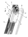
- the sliding guide for doors of wardrobes of the present invention comprises a per se known trolley 10', consisting in a first frame 12 shaped like an upturned "U", wherein the opposite and reciprocally parallel vertical walls 14 and 16 have different heights.
- Said trolley comprises a second frame 18, equally shaped like an upturned "U” and having a lower width than the first.
- the second frame is arranged underneath the first, wherefrom is suitably distanced, and has opposite and parallel vertical walls 20 and 20' of different heights.
- the trolley 10' comprising the frames 12 and 18 supporting the doors 22 and 24, as shown in figures 1 , 2 and 5 , is in fact arranged at the upper end of the piece of furniture, whereas at the base of the furniture thereof sliding guides of any known type can be provided.
- Said trolley comprising the frames 12 and 18 is combined with an extruded section 26, shown in figure 5 and per se known, comprising, along the horizontal development portion thereof, two distanced tracks the upper longitudinally extended end thereof defines a head 28 having semicircular section.
- the sliding guide comprising the trolley 10' with the frames 12, 18 and the relevant bearings 30, 32 is associated to a damper stop device apt to progressively slow down, at least during closing, the outer and inner doors, preventing them to abut roughly with the end stop.
- the damper stop device comprises an air damper, optionally a gas one, inserted in respective supports 34 and 36 consisting, for example, in metal tubulars opened at the lower front besides that on the heads and constrained near the semicircular head 28 of the tracks of the section 26.
- the planar development upper part 12' of the first frame 12 is provided with two longitudinally aligned windows wherefrom respective tabs 14', reciprocally distanced and parallel to the walls 14 and 16 of the frame thereof orthogonally bend downwards.
- a support 15 having substantially an upturned "U" section, wherein the opposed and parallel vertical walls 17, 17' have different heights and are connected by an integral band or horizontal development upper wall 19.
- An identical support 15 is arranged in the second frame 18 between the vertical walls 20 and 20'.
- the band 19 bends downwards at 90° onto at least a head of the support 15 and defines a tab 19' having a lower or equal height than the one of the wall 17'.
- the tab 19' is provided with a through opening 21, shaped in a way to have a lower part narrower than the upper part.
- Said support 15 is provided on the opposite vertical walls 17 and 17' of slots 29 inclined and reciprocally parallel, forming with the tab 19' with the through opening 21 and with a screw 23 associated to a block 23' a device for the height adjustment of the inner door 24 that shall be described hereinafter.
- the device thereof per se known on the other hand, is present as the support 15 also within the frame 18, although not shown, for the height adjustment of the outer door 22.
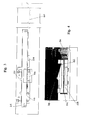
- the supports consisting of the metal tubulars 36 and 38 wherein are arranged the air dampers 38 are advantageously fixed to the wall 17 of each support 15 with the interposition of a strap 25, through rivets 27 or equivalent; with similar rivets 27' the air damper 38 as well as other elements 56 and 66 as specified hereinafter are fixed to the strap thereof and to the support 15 , as is shown in figure 6 , wherein for simplicity said strap 25 is shown only in association to the first frame 12.
- the height adjustment device of the inner 24 and outer 22 door is activated by each screw 23 coupled to the supports 15, said screws are provided with the block 23' with threaded hole for the screws thereof, which carry on the front end a groove apt to locate itself in the narrower lower end of the through opening 21.
- the block 23' on the other hand, abuts the inner front of the tab 19' and is fixed to the support 15 in a known way.
- the screwing and unscrewing of the screw 23 makes the block 23' advance or retract and the movements thereof take place along an inclined direction, set by the orientation of the slots 29; the second frame 18 is in this way adjusted in height, thus the inner door 24, as shown in figure 6 , which, as an example, regards the second frame 18 only.
- Each air damper whose reference numeral is 38, is associated to a coil spring 40, as shown in the figures from 13 to 16.
- the assembly composed by the air damper 38 and the coil spring 40 extending along the damper thereof as well as an extension 39 which seats the extended stem 44, is known on the market and comprises a cursor 42, consisting of a pivoting hook fixed at the front end of the stem 44 of said damper 38.
- a cursor 42 consisting of a pivoting hook fixed at the front end of the stem 44 of said damper 38.
- Each metal tubular forming the supports 34 and 36 seats an air damper 38 with the relevant coil spring 40, whereas the pivoting hook cursor 42 fixed at the front end of the stem 44 slides guided within a shaped slot 46, obtained within the extension 39 of the damper thereof, that is the portion wherein the stem 44 slides.
- the pivoting hook cursor 42 is intended to intercept an abutment, consisting in an activation unit or activator 48 shown in the figures 7, 8 and detailed in figure 10 , arranged and fixed in the vicinity of one end of the section 26.
- an activator 48 is placed within each seat 50 and 50' of said section 26 as shown in detail in figure 2 .
- Each activator 48 is provided, at least on one end, of an appendix 52, protruding upwards and in opposite direction from the semicircular head 28 of the tracks of the section 26; preferably, said appendix 52 is formed in correspondence of both ends or heads of activators 48, so as the latter can, if needed, be placed in the seats 50 and 50' of the section 26 and fixed thereon through a plaque 52' by means of generic screws.
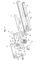
- each activator 48 protrudes at least in part an element in rubber or elastomeric material 54, that allows the dampening of the abutment between the activators thereof and as many supports or bumpers 56, shown in detail in figure 11 , fixed to the supports 15.
- the bumpers 56 have opposed shaped extremities 56' in order to adapt, according to the orientation thereof, to a retaining seat 58 of a clamp spring lock 60, arranged and stabilized in correspondence of the opening end stop of the guide 10.
- the bumpers 56 on one side act as an abutment with one end 56' to one of the rubber elements 54 of the activators 48 and, on the other side, temporarily engage the opposed end 56' in the retaining seat 58 of the clamp locks 60, equally provided with a damper rubber 72.
- a further element contributing to the optimal operation of the guide of the present invention consists in an anti-disengagement device 66, schematized in detail in figure 9 and arranged in correspondence of both the sliding tracks having semicircular head 28 of the bearings 30 and 32.
- said anti-disengagement devices comprise an upper block 68 with holes for the fastening through rivets or equivalent means in correspondence of the strap 25 of the respective supports 15 and a couple of integral and opposite walls 70 which extend downwards from the block 68 and which, at the lower end, have an inward bending which abuts below the semicircular head 28 of the tracks wherealong the bearings 30 and 32 slide.
- the anti-disengagement devices 66 contribute to prevent the overriding of the activator 48 by the dampers 38 arranged in the supports 34 and 36.
- the cursor 42 abuts with one of the appendixes 52 of the activator 48, follows the slot 46 pressing the stem 44 of the air damper 38 which performs the slowing down of the closing of the door.
- the starting situation of the closing stage of the door is schematically shown by figures 13 and 14 .
- the spring 40 fixed to the cursor 42 and previously extended upon opening of the door, progressively contracts and performs, in cooperation and in antithesis with the damper 38 the drawing free of shocks of the door up to the natural end stop thereof.
- the rubber element 54 of the activator 48 avoids a rough abutment and an eventual bump of the door upon the abutment between the activator thereof and the bumper 56; in particular, further than the function performed by the anti-disengagement devices 66, the rubber element 54 contributes to prevent that an eventual bump of the door leads the door thereof to override the activator 48 and to jam in the guide.
- the opposed head of the bumper 56 abuts in the clamp spring lock equally provided with the damper rubber 72.
- the sliding guide for doors of wardrobes of the invention guarantees reliability with regards to the damper elements, in relation thereto harmful fluid leaks cannot occur.
- the higher dimensions of air dampers, especially for applications on doors of significant weight, is not prejudicial for the structure of the guide as a whole, because the dampers thereof are located in an easy and innovative way in the sliding trolley rather than in the section.
Landscapes
- Engineering & Computer Science (AREA)
- Multimedia (AREA)
- Aviation & Aerospace Engineering (AREA)
- Physics & Mathematics (AREA)
- General Physics & Mathematics (AREA)
- Support Devices For Sliding Doors (AREA)
- Wing Frames And Configurations (AREA)
Applications Claiming Priority (1)
| Application Number | Priority Date | Filing Date | Title |
|---|---|---|---|
| IT000400U ITMI20090400U1 (it) | 2009-12-04 | 2009-12-04 | Guida scorrevole per ante armadi provvista di fermo ammortizzato |
Publications (2)
| Publication Number | Publication Date |
|---|---|
| EP2330269A2 true EP2330269A2 (de) | 2011-06-08 |
| EP2330269A3 EP2330269A3 (de) | 2014-05-21 |
Family
ID=43727576
Family Applications (1)
| Application Number | Title | Priority Date | Filing Date |
|---|---|---|---|
| EP10014215.7A Withdrawn EP2330269A3 (de) | 2009-12-04 | 2010-11-02 | Gleitführung für Türen von Kleiderschränken, die mit einem Dämpfungsanschlag versehen ist |
Country Status (2)
| Country | Link |
|---|---|
| EP (1) | EP2330269A3 (de) |
| IT (1) | ITMI20090400U1 (de) |
Cited By (9)
| Publication number | Priority date | Publication date | Assignee | Title |
|---|---|---|---|---|
| ITTV20130072A1 (it) * | 2013-05-09 | 2014-11-10 | Bortoluzzi Sistemi Spa | Dispositivo di smorzamento o richiamo per ante scorrevoli |
| EP2853671A1 (de) * | 2013-09-27 | 2015-04-01 | GEZE GmbH | Einzugsvorrichtung |
| WO2015121272A1 (de) * | 2014-02-14 | 2015-08-20 | Hettich-Heinze Gmbh & Co. Kg | Beschlag für eine schiebetür |
| EP3180487A4 (de) * | 2015-03-11 | 2018-03-14 | Dirtt Environmental Solutions, Ltd. | Taschenschiebetür |
| IT201700084318A1 (it) * | 2017-07-24 | 2019-01-24 | Bortoluzzi Sistemi Spa | “dispositivo anti-deragliamento per ante scorrevoli di mobili” |
| US10246923B2 (en) | 2014-11-11 | 2019-04-02 | Bortoluzzi Sistemi S.P.A. | Damping or return device for sliding door leaves or for drawers |
| EP3517718A1 (de) | 2018-01-29 | 2019-07-31 | Laguna Fabryka Okuc Spolka z o.o. S.K. | Schiebetürsystem mit leisen laufrollen |
| US10392848B2 (en) | 2014-11-11 | 2019-08-27 | Bortoluzzi Sistemi S.P.A. | Damping or return device for sliding door leaves |
| US11447997B2 (en) | 2014-11-24 | 2022-09-20 | Bortoluzzi Sistemi S.P.A. | Damping or return device for sliding door leaves or for drawers |
Family Cites Families (3)
| Publication number | Priority date | Publication date | Assignee | Title |
|---|---|---|---|---|
| JP2811634B2 (ja) * | 1996-04-08 | 1998-10-15 | 株式会社岡村製作所 | 引戸装置 |
| ITMI20071431A1 (it) * | 2007-07-17 | 2009-01-18 | Terno Scorrevoli Srl | Guida scorrevole per ante di armadi con dispositivo antisganciamento a innesto e disinnesto automatici dal rispoettivo binario |
| DE202008008006U1 (de) * | 2008-06-14 | 2009-10-29 | Gebr. Willach Gmbh | Schiebetür |
-
2009
- 2009-12-04 IT IT000400U patent/ITMI20090400U1/it unknown
-
2010
- 2010-11-02 EP EP10014215.7A patent/EP2330269A3/de not_active Withdrawn
Non-Patent Citations (1)
| Title |
|---|
| None |
Cited By (22)
| Publication number | Priority date | Publication date | Assignee | Title |
|---|---|---|---|---|
| US9752367B2 (en) | 2013-05-09 | 2017-09-05 | Bortoluzzi Sistemi S.P.A. | Damping or return device for sliding door leaves |
| WO2014180729A1 (en) * | 2013-05-09 | 2014-11-13 | Bortoluzzi Sistemi S.P.A. | A damping or return device for sliding door leaves |
| RU2673508C2 (ru) * | 2013-05-09 | 2018-11-27 | Бортолуцци Системи С.П.А. | Устройство для скользящих дверных полотен, обеспечивающее их скольжение и возврат |
| JP2016520744A (ja) * | 2013-05-09 | 2016-07-14 | ボルトルッツィ・システミ・ソチエタ・ペル・アツィオーニBORTOLUZZI SISTEMI S.p.A. | スライド扉の制動復帰装置 |
| ITTV20130072A1 (it) * | 2013-05-09 | 2014-11-10 | Bortoluzzi Sistemi Spa | Dispositivo di smorzamento o richiamo per ante scorrevoli |
| CN105189899B (zh) * | 2013-05-09 | 2018-04-06 | 博尔托卢齐系统股份公司 | 用于滑动门扇的阻尼或复位设备 |
| EP2853671A1 (de) * | 2013-09-27 | 2015-04-01 | GEZE GmbH | Einzugsvorrichtung |
| CN106103871A (zh) * | 2014-02-14 | 2016-11-09 | 海蒂诗-海因策有限及两合公司 | 用于滑动门的装置 |
| RU2674000C2 (ru) * | 2014-02-14 | 2018-12-03 | Хеттих-Хайнце Гмбх Унд Ко. Кг | Фурнитура для раздвижной двери |
| JP2017510733A (ja) * | 2014-02-14 | 2017-04-13 | ヘティッヒ‐ハインゼ ゲーエムベーハー ウント ツェーオー. カーゲー | スライド式ドア用の嵌合具 |
| WO2015121272A1 (de) * | 2014-02-14 | 2015-08-20 | Hettich-Heinze Gmbh & Co. Kg | Beschlag für eine schiebetür |
| US10246923B2 (en) | 2014-11-11 | 2019-04-02 | Bortoluzzi Sistemi S.P.A. | Damping or return device for sliding door leaves or for drawers |
| US10392848B2 (en) | 2014-11-11 | 2019-08-27 | Bortoluzzi Sistemi S.P.A. | Damping or return device for sliding door leaves |
| US11447997B2 (en) | 2014-11-24 | 2022-09-20 | Bortoluzzi Sistemi S.P.A. | Damping or return device for sliding door leaves or for drawers |
| EP3180487A4 (de) * | 2015-03-11 | 2018-03-14 | Dirtt Environmental Solutions, Ltd. | Taschenschiebetür |
| US10273743B2 (en) | 2015-03-11 | 2019-04-30 | Dirtt Environmental Solutions, Ltd. | Pocket door |
| IT201700084318A1 (it) * | 2017-07-24 | 2019-01-24 | Bortoluzzi Sistemi Spa | “dispositivo anti-deragliamento per ante scorrevoli di mobili” |
| WO2019021100A1 (en) * | 2017-07-24 | 2019-01-31 | Bortoluzzi Sistemi S.P.A. | ANTI-DERAILING DEVICE FOR SLIDING PANELS OF FURNITURE ELEMENTS |
| CN110998050A (zh) * | 2017-07-24 | 2020-04-10 | 博尔托卢齐系统股份公司 | 用于家具产品的滑动扇页的防脱轨装置 |
| CN110998050B (zh) * | 2017-07-24 | 2022-01-28 | 博尔托卢齐系统股份公司 | 用于家具产品的滑动扇页的防脱轨装置 |
| RU2768339C2 (ru) * | 2017-07-24 | 2022-03-23 | Бортолуцци Системи С.П.А. | Устройство предотвращения схода для скользящих створок предметов мебели |
| EP3517718A1 (de) | 2018-01-29 | 2019-07-31 | Laguna Fabryka Okuc Spolka z o.o. S.K. | Schiebetürsystem mit leisen laufrollen |
Also Published As
| Publication number | Publication date |
|---|---|
| EP2330269A3 (de) | 2014-05-21 |
| ITMI20090400U1 (it) | 2011-06-05 |
Similar Documents
| Publication | Publication Date | Title |
|---|---|---|
| EP2330269A2 (de) | Gleitführung für Türen von Kleiderschränken, die mit einem Dämpfungsanschlag versehen ist | |
| EP2330268B1 (de) | Führungsschiene für Türen mit Enddämpfung | |
| EP1692969B1 (de) | Führungseinrichtung für Schubladen | |
| EP1774870B1 (de) | Ausziehführung für Schubladen | |
| CN107923218B (zh) | 合页侧的手指保护装置 | |
| CN102065726A (zh) | 用于抽屉滑动装置的控制机构 | |
| US20100141106A1 (en) | Soft close drawer assembly and bracket | |
| KR101151895B1 (ko) | 미닫이식 도어의 개폐장치 | |
| CN101991285A (zh) | 抽屉组件 | |
| US11519209B2 (en) | Sliding doors floor handling device | |
| WO2000023683A1 (en) | Storage bin with counterbalanced door | |
| CN105142462A (zh) | 用于可移动的家具部件的拉出导向件 | |
| CN108825028B (zh) | 一种推拉门滑动轮组合件 | |
| EP1640537B1 (de) | Stossdämpfende und stabilisierende Stoppvorrichting für Schiebetüren und -läden | |
| EP2048311B1 (de) | Stoßdämpfende Stoppvorrichtung für Schiebepaneele und -Türen | |
| EP3655608A1 (de) | Scharnier für türen von küchenöfen | |
| RU2632397C2 (ru) | Подвижная деталь для направленного перемещения детали мебели в направлении перемещения и мебельная фурнитура | |
| RU2468171C2 (ru) | Мебельная петля | |
| CN108756567B (zh) | 一种移门缓冲器 | |
| RU2458222C2 (ru) | Механизм для раздвижной двери | |
| KR200450830Y1 (ko) | 사물함 경첩 | |
| RU2675209C2 (ru) | Конструкция раздвижной двери с раздвижными створками, расположенными в общей плоскости | |
| KR200300419Y1 (ko) | 도어용 안전장치 | |
| KR200449640Y1 (ko) | 사물함 경첩 | |
| US20140042884A1 (en) | Control mechanism for drawer slide assembly |
Legal Events
| Date | Code | Title | Description |
|---|---|---|---|
| PUAI | Public reference made under article 153(3) epc to a published international application that has entered the european phase |
Free format text: ORIGINAL CODE: 0009012 |
|
| AK | Designated contracting states |
Kind code of ref document: A2 Designated state(s): AL AT BE BG CH CY CZ DE DK EE ES FI FR GB GR HR HU IE IS IT LI LT LU LV MC MK MT NL NO PL PT RO RS SE SI SK SM TR |
|
| AX | Request for extension of the european patent |
Extension state: BA ME |
|
| PUAL | Search report despatched |
Free format text: ORIGINAL CODE: 0009013 |
|
| AK | Designated contracting states |
Kind code of ref document: A3 Designated state(s): AL AT BE BG CH CY CZ DE DK EE ES FI FR GB GR HR HU IE IS IT LI LT LU LV MC MK MT NL NO PL PT RO RS SE SI SK SM TR |
|
| AX | Request for extension of the european patent |
Extension state: BA ME |
|
| RIC1 | Information provided on ipc code assigned before grant |
Ipc: E05F 5/00 20060101ALI20140414BHEP Ipc: E05F 1/16 20060101ALI20140414BHEP Ipc: E05D 15/06 20060101AFI20140414BHEP |
|
| 17P | Request for examination filed |
Effective date: 20141021 |
|
| RBV | Designated contracting states (corrected) |
Designated state(s): AL AT BE BG CH CY CZ DE DK EE ES FI FR GB GR HR HU IE IS IT LI LT LU LV MC MK MT NL NO PL PT RO RS SE SI SK SM TR |
|
| 17Q | First examination report despatched |
Effective date: 20160224 |
|
| STAA | Information on the status of an ep patent application or granted ep patent |
Free format text: STATUS: EXAMINATION IS IN PROGRESS |
|
| STAA | Information on the status of an ep patent application or granted ep patent |
Free format text: STATUS: THE APPLICATION IS DEEMED TO BE WITHDRAWN |
|
| 18D | Application deemed to be withdrawn |
Effective date: 20170318 |