EP2329876B1 - PM clean-up system and method for manufacture thereof - Google Patents
PM clean-up system and method for manufacture thereof Download PDFInfo
- Publication number
- EP2329876B1 EP2329876B1 EP10014319A EP10014319A EP2329876B1 EP 2329876 B1 EP2329876 B1 EP 2329876B1 EP 10014319 A EP10014319 A EP 10014319A EP 10014319 A EP10014319 A EP 10014319A EP 2329876 B1 EP2329876 B1 EP 2329876B1
- Authority
- EP
- European Patent Office
- Prior art keywords
- particulate matter
- active oxygen
- filter substrate
- catalyst
- producing fine
- Prior art date
- Legal status (The legal status is an assumption and is not a legal conclusion. Google has not performed a legal analysis and makes no representation as to the accuracy of the status listed.)
- Ceased
Links
Images


Classifications
-
- F—MECHANICAL ENGINEERING; LIGHTING; HEATING; WEAPONS; BLASTING
- F01—MACHINES OR ENGINES IN GENERAL; ENGINE PLANTS IN GENERAL; STEAM ENGINES
- F01N—GAS-FLOW SILENCERS OR EXHAUST APPARATUS FOR MACHINES OR ENGINES IN GENERAL; GAS-FLOW SILENCERS OR EXHAUST APPARATUS FOR INTERNAL-COMBUSTION ENGINES
- F01N3/00—Exhaust or silencing apparatus having means for purifying, rendering innocuous, or otherwise treating exhaust
- F01N3/02—Exhaust or silencing apparatus having means for purifying, rendering innocuous, or otherwise treating exhaust for cooling, or for removing solid constituents of, exhaust
- F01N3/021—Exhaust or silencing apparatus having means for purifying, rendering innocuous, or otherwise treating exhaust for cooling, or for removing solid constituents of, exhaust by means of filters
- F01N3/022—Exhaust or silencing apparatus having means for purifying, rendering innocuous, or otherwise treating exhaust for cooling, or for removing solid constituents of, exhaust by means of filters characterised by specially adapted filtering structure, e.g. honeycomb, mesh or fibrous
- F01N3/0222—Exhaust or silencing apparatus having means for purifying, rendering innocuous, or otherwise treating exhaust for cooling, or for removing solid constituents of, exhaust by means of filters characterised by specially adapted filtering structure, e.g. honeycomb, mesh or fibrous the structure being monolithic, e.g. honeycombs
-
- B—PERFORMING OPERATIONS; TRANSPORTING
- B01—PHYSICAL OR CHEMICAL PROCESSES OR APPARATUS IN GENERAL
- B01D—SEPARATION
- B01D53/00—Separation of gases or vapours; Recovering vapours of volatile solvents from gases; Chemical or biological purification of waste gases, e.g. engine exhaust gases, smoke, fumes, flue gases, aerosols
- B01D53/34—Chemical or biological purification of waste gases
- B01D53/92—Chemical or biological purification of waste gases of engine exhaust gases
- B01D53/94—Chemical or biological purification of waste gases of engine exhaust gases by catalytic processes
- B01D53/944—Simultaneously removing carbon monoxide, hydrocarbons or carbon making use of oxidation catalysts
-
- B—PERFORMING OPERATIONS; TRANSPORTING
- B01—PHYSICAL OR CHEMICAL PROCESSES OR APPARATUS IN GENERAL
- B01J—CHEMICAL OR PHYSICAL PROCESSES, e.g. CATALYSIS OR COLLOID CHEMISTRY; THEIR RELEVANT APPARATUS
- B01J23/00—Catalysts comprising metals or metal oxides or hydroxides, not provided for in group B01J21/00
- B01J23/38—Catalysts comprising metals or metal oxides or hydroxides, not provided for in group B01J21/00 of noble metals
- B01J23/54—Catalysts comprising metals or metal oxides or hydroxides, not provided for in group B01J21/00 of noble metals combined with metals, oxides or hydroxides provided for in groups B01J23/02 - B01J23/36
- B01J23/56—Platinum group metals
- B01J23/58—Platinum group metals with alkali- or alkaline earth metals
-
- B—PERFORMING OPERATIONS; TRANSPORTING
- B01—PHYSICAL OR CHEMICAL PROCESSES OR APPARATUS IN GENERAL
- B01J—CHEMICAL OR PHYSICAL PROCESSES, e.g. CATALYSIS OR COLLOID CHEMISTRY; THEIR RELEVANT APPARATUS
- B01J23/00—Catalysts comprising metals or metal oxides or hydroxides, not provided for in group B01J21/00
- B01J23/38—Catalysts comprising metals or metal oxides or hydroxides, not provided for in group B01J21/00 of noble metals
- B01J23/54—Catalysts comprising metals or metal oxides or hydroxides, not provided for in group B01J21/00 of noble metals combined with metals, oxides or hydroxides provided for in groups B01J23/02 - B01J23/36
- B01J23/56—Platinum group metals
- B01J23/63—Platinum group metals with rare earths or actinides
-
- B—PERFORMING OPERATIONS; TRANSPORTING
- B01—PHYSICAL OR CHEMICAL PROCESSES OR APPARATUS IN GENERAL
- B01J—CHEMICAL OR PHYSICAL PROCESSES, e.g. CATALYSIS OR COLLOID CHEMISTRY; THEIR RELEVANT APPARATUS
- B01J37/00—Processes, in general, for preparing catalysts; Processes, in general, for activation of catalysts
- B01J37/02—Impregnation, coating or precipitation
- B01J37/024—Multiple impregnation or coating
- B01J37/0244—Coatings comprising several layers
-
- F—MECHANICAL ENGINEERING; LIGHTING; HEATING; WEAPONS; BLASTING
- F01—MACHINES OR ENGINES IN GENERAL; ENGINE PLANTS IN GENERAL; STEAM ENGINES
- F01N—GAS-FLOW SILENCERS OR EXHAUST APPARATUS FOR MACHINES OR ENGINES IN GENERAL; GAS-FLOW SILENCERS OR EXHAUST APPARATUS FOR INTERNAL-COMBUSTION ENGINES
- F01N3/00—Exhaust or silencing apparatus having means for purifying, rendering innocuous, or otherwise treating exhaust
- F01N3/02—Exhaust or silencing apparatus having means for purifying, rendering innocuous, or otherwise treating exhaust for cooling, or for removing solid constituents of, exhaust
- F01N3/021—Exhaust or silencing apparatus having means for purifying, rendering innocuous, or otherwise treating exhaust for cooling, or for removing solid constituents of, exhaust by means of filters
- F01N3/033—Exhaust or silencing apparatus having means for purifying, rendering innocuous, or otherwise treating exhaust for cooling, or for removing solid constituents of, exhaust by means of filters in combination with other devices
-
- B—PERFORMING OPERATIONS; TRANSPORTING
- B01—PHYSICAL OR CHEMICAL PROCESSES OR APPARATUS IN GENERAL
- B01D—SEPARATION
- B01D2255/00—Catalysts
- B01D2255/90—Physical characteristics of catalysts
- B01D2255/908—O2-storage component incorporated in the catalyst
-
- F—MECHANICAL ENGINEERING; LIGHTING; HEATING; WEAPONS; BLASTING
- F01—MACHINES OR ENGINES IN GENERAL; ENGINE PLANTS IN GENERAL; STEAM ENGINES
- F01N—GAS-FLOW SILENCERS OR EXHAUST APPARATUS FOR MACHINES OR ENGINES IN GENERAL; GAS-FLOW SILENCERS OR EXHAUST APPARATUS FOR INTERNAL-COMBUSTION ENGINES
- F01N2250/00—Combinations of different methods of purification
- F01N2250/02—Combinations of different methods of purification filtering and catalytic conversion
-
- Y—GENERAL TAGGING OF NEW TECHNOLOGICAL DEVELOPMENTS; GENERAL TAGGING OF CROSS-SECTIONAL TECHNOLOGIES SPANNING OVER SEVERAL SECTIONS OF THE IPC; TECHNICAL SUBJECTS COVERED BY FORMER USPC CROSS-REFERENCE ART COLLECTIONS [XRACs] AND DIGESTS
- Y02—TECHNOLOGIES OR APPLICATIONS FOR MITIGATION OR ADAPTATION AGAINST CLIMATE CHANGE
- Y02T—CLIMATE CHANGE MITIGATION TECHNOLOGIES RELATED TO TRANSPORTATION
- Y02T10/00—Road transport of goods or passengers
- Y02T10/10—Internal combustion engine [ICE] based vehicles
- Y02T10/12—Improving ICE efficiencies
-
- Y—GENERAL TAGGING OF NEW TECHNOLOGICAL DEVELOPMENTS; GENERAL TAGGING OF CROSS-SECTIONAL TECHNOLOGIES SPANNING OVER SEVERAL SECTIONS OF THE IPC; TECHNICAL SUBJECTS COVERED BY FORMER USPC CROSS-REFERENCE ART COLLECTIONS [XRACs] AND DIGESTS
- Y10—TECHNICAL SUBJECTS COVERED BY FORMER USPC
- Y10T—TECHNICAL SUBJECTS COVERED BY FORMER US CLASSIFICATION
- Y10T29/00—Metal working
- Y10T29/49—Method of mechanical manufacture
- Y10T29/49345—Catalytic device making
Definitions
- This invention relates to a device comprising a catalyst for purifying combustion exhaust gas of a diesel engine or the like, and more particularly, to a catalyst for removing particulate matter, especially carbon soot particles contained in the exhaust gas, and to a manufacturing method thereof.
- Japanese Patent Laid-Open No. 9-94434 discloses a wall flow type waste gas purifying filter. According to the invention disclosed in Japanese Patent Laid-Open No. 9-94434 , the particulate matter is trapped in the pores formed in a filter substrate when the exhaust gas passes therethrough, and the particulate matter is oxidized by a catalyst carried inside of the pores.
- Japanese Patent Publication No. 07-106290 discloses a catalyst mixture consisting essentially of a platinum group metal and an alkaline earth metal oxide which is used in the filter of this kind. According to the invention disclosed in Japanese Patent Publication No. 07-106290 , the catalyst mixture is carried on the filter element walls by a deposition method. Also, Japanese Patent Laid-Open No. 2001-271634 discloses an exhaust emission control device, in which a carried catalyst contains an active oxygen discharging agent.
- a filter for removing the particulate matter is adapted to trap the particulate matter contained in the exhaust gas on an outer surface of a porous filter wall (or filter substrate) and an inner surface of a pore, when the exhaust gas passes through the filter wall.
- the trapped particulate matter is removed by oxidizing (or combusting) the trapped particulate matter aggressively through the catalyst.
- the oxidation reaction is produced by active oxygen produced by the catalyst taught by Japanese Patent Laid-Open No. 9-94434 or Japanese Patent Publication No. 07-106290 , or by active oxygen emitted in a reducing atmosphere from the active oxygen discharging agent contained in the catalyst taught by Japanese Patent Laid-Open No. 2001-271634 .
- the activation region is limited within the range of several nm from the place where the active oxygen is produced.
- the catalyst is carried on the filter substrate by a various method e.g., by a deposition method taught by Japanese Patent Publication No. 07-106290 .
- the catalyst since the catalyst is a particulate material, the catalyst may not always be carried densely on the surface of the filter substrate.
- an uncoated area 4 where the surface of the filter substrate 3 is exposed is created between catalyst particles 1 as illustrated in Fig. 5 (B) .
- a distance of the uncoated area 4 is several ⁇ m to about 100 ⁇ m, a particulate matter 5 may adhere to (or is trapped on) the uncoated area 4, and the particulate matter 5 may be deposited thereon without being oxidized by the active oxygen.
- the particulate matter 5 thus deposited does not comprises a catalytic element on its surface. Moreover, since the particulate matter 5 thus deposited is distant from the peripheral catalyst particles 1, there still remains the uncoated area 4. Therefore, the subsequent particulate matter 5 will adhere thereto and will be deposited without being oxidized.
- Fig. 5 (A) schematically shows such sedimentation. As shown in Fig. 5 (A) , the particulate matter 5 adheres to and deposited on the uncoated area 4 grows gradually to form a bridge beam like shape. Eventually, adjoining upper end portions of the bridge beams will be connected with each other. As a result, the particulate matter 5 forms a porous membrane 6 on an outer surface of the filter substrate 3.
- the porous membrane 6 is formed on the outer surface of the filter substrate 3, the particulate matter 5 in an exhaust gas is trapped by the porous membrane 6 when the exhaust gas passes through the porous membrane 6. This means that, the particulate matter 5 cannot reach the filter substrate 3 carrying the catalyst thereon. That is, although it is possible to trap the particulate matter 5, the particulate matter 5 cannot be oxidized to be removed. As a result, an amount of the trapped particulate matter 5 may be accumulated excessive.
- the uncoated area without having the catalyst also exists on an inner surface of a pore 7 in the filter substrate 3; however, above-explained sedimentation is not especially confirmed.
- the particulate matter 5 may be moved within the pore 7 to be oxidized due to the fact that: the spatial configuration in the pore 7 is rather complicated; the flow rate of the exhaust gas is high; and the flow force of the exhaust gas is likely to act on the particulate matter 5 to move the particulate matter 5 along the inner surface of the pore 7.
- US 6,294,140 discloses a catalyst for treating exhaust gas from an internal combustion engine includes a carrier body coated with an inner layer and an outer layer.
- the inner layer includes platinum deposited on a first support material and on a first oxygen storage component
- the outer layer includes platinum and rhodium deposited on a second support material and on a second oxygen storage component.
- US 6,255,249 discloses oxidation catalyst compositions including a catalyst material having a BET surface area of at least about 10 m 2 /g and consisting essentially of a combination of bulk ceria and a bulk second metal oxide which may be one or more of titania, zirconia, ceria-zirconia, silica, alumina-silica and ⁇ -alumina.
- the combination may optionally also include activated alumina having a BET surface area of at least about 10 m 2 /g.
- the catalyst compositions may be used for oxidation of oxidizeable components in a gas-borne stream, e.g., in a method to treat diesel engine exhaust by contacting the hot exhaust with the catalyst composition to promote the oxidation of the volatile organic fraction.
- US 5,627,124 discloses oxidation catalyst compositions including a catalytic material containing ceria- and alumina each having a surface area of at least about 10 m 2 /g, for example, ceria and activated alumina in weight ratio of from about 1.5:1 to 1:1.5.
- the catalyst composition shave utility as oxidation catalysts for pollution abatement of exhausts containing unburned fuel or oil.
- the present invention has been conceived noting the aforementioned technical problems, and has an object to provide a particulate matter purifying device capable of preventing particulate matter from being deposited excessively on an outer surface of a filter substrate, and to provide a manufacturing method thereof.
- the nonpolar solvent solution is attached to the portion where the polarity thereof is comparatively weak (e.g., the portion consisting of SiO 2 in case of cordierite), and a metallic oxide such as alumina is separated out when dried and sintered at a subsequent process.
- the hydrophilic portion e.g., the portion consisting of MgO or MgOH in case of cordierite
- the hydrophilic metallic alkoxide is hydrized so that a metallic oxide such as alumina is separated out.
- the metal oxide layer of alumina or the like is formed homogeneously all over the surface of the filter substrate.
- the active oxygen producing fine particles or the active oxygen producing fine particulate layer can be formed homogeneously through the metal oxide layer.
- the particulate matter purifying device of the present invention comprises a filter substrate 10 for trapping particulate matter contained in exhaust gas emitted from a thermal engine such as a diesel engine.
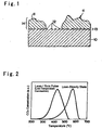
- Fig. 1 schematically shows a portion of a filter substrate 10 in an enlarged scale.
- the filter substrate 10 is made of porous ceramic. Specifically, cordierite (2MgO ⁇ 2Al 2 O 3 ⁇ 5SiO 2 ), carborundum (SiC), a nonwoven ceramic, a wire mesh and so on can be used as the filter substrate 10.
- a catalyst element 11 is carried on the filter substrate 10.
- the catalyst element 11 is selected from a noble metal, an NOx occlusion material and an oxygen occlusion material according to the purpose of purification of exhaust gas.
- platinum (Pt), palladium (Pd), rhodium (Rh) or the like is carried as the noble metal
- barium (Ba) is carried as the NOx occlusion material
- ceria (CeO 2 ) is carried as the oxygen occlusion material.
- Those catalyst elements 11 may be carried by a known method, such as a slurry method (or an impregnation method) in which slurry containing the above-mentioned catalyst elements is adsorbed to the filter substrate 10 and then dried and sintered, or a dipping method in which the filter substrate 10 is dipped into a solution containing the above-mentioned catalyst elements and then dried and sintered.
- a slurry method or an impregnation method
- slurry containing the above-mentioned catalyst elements is adsorbed to the filter substrate 10 and then dried and sintered
- a dipping method in which the filter substrate 10 is dipped into a solution containing the above-mentioned catalyst elements and then dried and sintered.
- the catalyst elements 11 having the grain diameter of several tens ⁇ m are used, and such catalyst elements 11 are dispersed and carried on the filter substrate 10.
- the catalyst elements 11 are isolated from each other due to a local concentration difference thereof or the like when they are carried.
- a portion where the catalyst element 11 is not carried is created on the surface of the filter substrate 10 in the range from several ⁇ m to approximately 100 ⁇ m. This area corresponds to the aforementioned uncoated area 4.
- Active oxygen producing fine particles 12 are carried on the portion corresponding to the uncoated area 4.
- the active oxygen producing fine particles 12 are fine particles of oxides or compound oxides which produce active oxygen (O 2 - ) in a reducing atmosphere, for example, magnesium oxide (MgO), ceria (CeO 2 ), ceria zirconia compound oxide (CeZrOx) and so on.
- a grain diameter of the active oxygen producing fine particles 12 is as small as possible.
- the active oxygen producing fine particles 12 are adjusted to have a diameter of 1 ⁇ m to 10 ⁇ m.
- the active oxygen producing fine particles 12 are dispersed on the surface of the filter substrate 10 homogeneously as much as possible to form an active oxygen producing fine particulate layer 13, instead of carrying the active oxygen producing fine particles 12 selectively on the portion corresponding to the uncoated area 4 between the catalyst elements 11. Then, the catalyst elements 11 are carried thereon to form a catalyst carrying layer 14. As a result, even if clearances exist between the catalyst elements 11, the active oxygen producing fine particles 12 forming the active oxygen producing fine particulate layer 13 are exposed on in the clearance. That is; the active oxygen producing fine particles 12 are arranged between the catalyst elements 11.
- a lipophilic solution containing phenyl groups or the like is adsorbed to the filter substrate 10 first of all, then, ionized or complex ionized active oxygen producing fine particles 12 are adsorbed thereon, and then, dried and sintered.
- the active oxygen producing fine particles 12 are dispersed by an electrical force so that the active oxygen producing fine particles 12 can be carried on the filter substrate 10 homogeneously.
- a benzalkonium chloride solution, a pyromellitic solution, a fumaric solution, an organic acid-base solution and so on may be used as the lipophilic solution.
- the filter substrate 10 thus carrying the catalyst elements 11 and the active oxygen producing fine particles 12 is used to constitute a wall through type particulate matter purifying device, which traps particulate matter contained in exhaust gas of a diesel engine or the like by transmitting the exhaust gas therethrough.
- the particulate matter may be trapped both on the catalyst elements 11 and on the portion other than the catalyst elements 11.
- the active oxygen producing fine particles 12 are exposed as explained above. Therefore, the particulate matter trapped on the portion where the catalyst element 11 does not exist may not be oxidized directly by the catalyst element 11. However, the trapped particulate matter adheres to the active oxygen producing fine particles 12. Accordingly, for example, when active oxygen is produced in the reducing atmosphere, the particulate matter adhering to the active oxygen producing fine particles 12 is oxidized by the produced active oxygen.
- the trapped particulate matter adhering to the catalyst element 11 is oxidized and removed through the catalyst. Therefore, the oxidization of the particulate matter trapped on the portion outside the reach of the oxidization of the catalyst element 11 can be promoted by the active oxygen produced by the active oxygen producing fine particles 12, so that the particulate matter trapped on such portion can be oxidized to be removed at comparatively low temperature. For this reason, an excessive deposition of the particulate matter can be avoided or minimized. Therefore, the filter substrate 10 and the particulate matter purifying device can be prevented from being damaged by an impetuous burning of the deposition of the particulate matter at high temperature.
- the active oxygen producing fine particles 12 are carried between the catalyst elements 11. Therefore, it is preferable to carry the active oxygen producing fine particles 12 homogeneously as much as possible.
- an intermediate layer is formed, on which the active oxygen producing fine particulate layer 13 is to be formed, instead of carrying the active oxygen producing fine particles 12 directly on the filter substrate 10. That is, the intermediate layer is an oxide layer 15, which is provided to eliminate variation in affinity of the surface of the filter substrate 10 for the active oxygen producing fine particles 12.
- the oxide layer 15 is formed of an oxidative product such as alumina, silica, zirconia or the like, or a compound oxide containing those oxidative products.
- the material of the oxide layer 15 is an oxidative product or a compound oxide different from those of the filter substrate 10 and the active oxygen producing fine particles 12. An example thereof is shown schematically in Fig. 4 .
- the oxide layer 15 can be formed by the method to be explained in the following.
- the filter substrate 10 made of cordierite or the like has both hydrophilic portion and lipophilic portion. Therefore, first of all, the filter substrate 10 is dipped into a nonpolar solvent mixed with an organic metallic compound.
- a solvent of hexane, cychlohexane, toluene, 1-butanole, 1-hexanol or the like may be suitable to be used as the nonpolar solvent.
- a solvent whose polarity is weak, i.e., relative permittivity is less than 20 is suitable.
- metallic alkoxide such as aluminum alkoxide or the like can be used as the metallic compound.
- the hydrophilic metallic alkoxide is hydrized so that a metallic oxide is separated out.
- the hydrophilicity of the nonpolar solvent to the nonhydrophilic portion is excellent so that the nonpolar solvent adsorbs to the nonhydrophilic portion sufficiently. For this reason, a large amount of the metallic oxide is separated out when dried and sintered.
- the metallic oxide is carried in conformity with the two different characteristics of the filter substrate 10. Therefore, the oxide layer can be formed homogeneously all over the surface of the filter substrate 10.
- the complex ion adsorption method can also be used to adsorb the active oxygen producing fine particles 12 converted into complex ions.
- an organic acid such as succinic acid, malic acid, tartaric acid, citric acid or the like can be used to produce the complex ion.
- cordierite for the filter substrate was dipped into an aqueous solution prepared by dissolving 70 gram of metallic alkoxide such as aluminum alkoxide (aluminum tri-sec-butoxide, to be abbreviated as "ASBD" hereinafter) into 4 liters of a nonpolar solvent of cyclohexane. After lifting the cordierite substrate from the solution, extra solution was blown off, and then the cordierite substrate was dried and sintered. As a result, alumina was produced on the cordierite substrate homogeneously.
- metallic alkoxide such as aluminum alkoxide (aluminum tri-sec-butoxide, to be abbreviated as "ASBD” hereinafter
- particle CeZrO 4 as the active oxygen producing fine particles was adsorbed to the cordierite substrate where alumina was separated out, by the complex ion adsorption method.
- a complex ionic solution as a mixed liquid of zirconium and cerium
- 0.05 mols of oxynitrate zirconium and cerium nitrate were collected individually, and dissolved in 4 liters of distilled water.
- 118g of ammonium dihydrogen citrate, and 61g of ammonium citrate tribasic were added into the solution.
- the cordierite substrate to which alumina was adsorbed was dipped into the complex ionic solution to adsorb complex ions.
- the cordierite substrate was moved up and down in the solution, and this absorption process was continued for one hour.
- zirconium complex ions and cerium complex ions in the solution were absorbed to the cordierite substrate almost completely.
- the cordierite substrate to which the aforementioned complex ions were adsorbed was coated with a carrier, and noble metal and NOx occlusion material were carried thereon.
- a DPNR catalyst was prepared.
- Those coating process of the carrier, and the carrying process of the noble metal and NOx occlusion material were carried out by known methods. Specifically, the cordierite substrate is impregnated with slurry containing alumina and alumina sol, and then dried and sintered to form a coat layer. After that, the cordierite substrate was impregnated with a predetermined amount of barium acetate of predetermined concentration, and heated to carry barium (Ba). Then, the carried barium was changed into carbonate using ammonium bicarbonate.
- a DPNR catalyst was prepared by a conventional method. Specifically, the DPNR catalyst was prepared by coating a cordierite substrate with a carrier, and by carrying noble metal and NOx occlusion material thereon, without carrying out a process of adborbing particle CeZrO 4 of the example 1.
- a deposition amount of the particulate matter was measured. If the filter functions properly, the particulate matter enters into pores formed on the filter substrate. Consequently, a predetermined relation is established between the deposition amount and a pressure drop. This means that the deposition amount of the particulate matter can be found by detecting a pressure of exhaust gas. However, as explained with reference to Fig. 5 , if the particulate matter deposits on the outer surface of the filter substrate, the particulate matter grows to form a bridge beam like shape. Eventually, adjoining upper end portions of the bridge beams will be connected with each other. As a result, the particulate matter forms a porous membrane on an outer surface of the filter substrate.
- the porous membrane is formed on the outer surface of the filter substrate, the particulate matter is trapped by the porous membrane. That is, the particulate matter will not enter into the pores. This means that the relation between deposition amount and the pressure drop will be no longer available. For this reason, the deposited particulate matter is directly oxidized to be changed into CO 2 in both DPNR catalysts of the example 1 and the comparison example, and the evaluations were made by analyzing CO 2 .
- a vehicle equipped with an inline four-cylinder direct diesel-injection engine was used in the experimentations.
- the engine was equipped with the (2 liter of) DPNR catalysts of the example 1 and the comparison example in each experiment.
- an endurance running of the vehicle of 200 kilometer at the maximum speed of 120km/h was carried out, and then, a deposition amount of the particulate matter was measured.
- a rich spiking of 2 seconds at intervals of 20 seconds was carried out.
- the deposition amount of the particulate matter was 4.5g/L according to the DPNR of the comparison example.
- the DPNR of the example 1 the deposition amount of the particulate matter was only 0.9g/L.
- the deposition amount of the particulate matter was reduced drastically. This means that oxidation capacity of the particulate matter is improved.
- the particulate matter adsorbed or trapped on the portion of the outer surface of the filter substrate where the catalyst element does not exist can be easily oxidized by the active oxygen produced by the active oxygen producing particles existing thereon. Therefore, the particulate matter is prevented from growing into the bridge beam like shape or the porous membrane, and allowed to enter into the catalyst layer of the filter substrate successively to be oxidized and removed. For this reason, the deposition of the particulate matter is prevented from being progressed.
- the active oxygen producing fine particles are carried homogeneously, in other words, the active oxygen producing fine particulate layer is formed homogeneously.
- the oxide layer is formed as an intermediate layer between the active oxygen producing fine particulate layer and the filter (or cordierite) substrate, for the purpose of forming the active oxygen producing fine particulate layer homogeneously. It is estimated that the oxide layer functions as explained in the following.
- the cordierite substrate comprises portions having a small amount of hydroxyl group (i.e., hydrophilic portions) where hydrophilic ASBD is hydrolyzed, and alumina is separated out on these portions.
- hydrophilicity of the remaining portion of the cordierite substrate having no hydrophilic group is excellent with respect to the aqueous solution of cyclohexane the polarity thereof is weak. Therefore, the aqueous solution of cyclohexane mixed with aluminum alkoxide adheres amply to the portion of the cordierite substrate having no hydrophilic group. That is, alumina is separated out amply on such portion when dried and sintered.
- the cordierite substrate comprises two kinds of portions having different characteristics on its surface.
- the active oxygen producing fine particulate layer can also be formed directly on the filter substrate of cordierite or the like.
- the example will be explained hereinafter as the example 2.
- the filter substrate was coated with a carrier, and noble metal and NOx occlusion material were carried thereon by a known method to prepare DPNR catalyst.
- particle CeZrO 4 functioning as the active oxygen producing fine particles can be dispersed and adsorbed on the filter substrate homogeneously.
- the active oxygen producing fine particles are exposed on such area.
- the particulate matter adsorbed or trapped on such area is damaged by the active oxygen, and the oxidization of the particulate matter is thereby facilitated. For this reason, an excessive deposition of the particulate matter can be avoided or minimized.
- the active oxygen producing fine particulate layer is thus formed homogeneously by the function of the benzalkonium chloride solution. That is, since benzalkonium chloride contains lipophilic group, affinity thereof for the filter substrate of cordierite is excellent. Moreover, the surface of the filter substrate is charged to the plus polarity when benzalkonium chloride is adsorbed thereon. To the contrary, the aforementioned complex ions are charged to the minus polarity. That is, the complex ions and the filter substrate interact strongly with each other so that the complex ions are electrically adsorbed to almost all over the portion of the filter substrate charged to the plus polarity. As a result, the complex ions, which form the active oxygen producing fine particulate layer, are dispersed and adsorbed homogeneously on the filter substrate. For this reason, the active oxygen producing fine particulate layer can be formed homogeneously.
- the engine was driven for 30 minutes under the above-mentioned condition, and the DPNR catalyst was then taken off. After that, a deposition amount of the particulate matter (i.e., carbon) in the filter was obtained from an amount of CO 2 emitted by the reaction with the air in an electric furnace.
- the particulate matter i.e., carbon
- This invention can be utilized in the field for manufacturing a device for generating power by burning a fuel, and in the field to manufacture a device for purifying an exhaust gas
Landscapes
- Chemical & Material Sciences (AREA)
- Engineering & Computer Science (AREA)
- Chemical Kinetics & Catalysis (AREA)
- Materials Engineering (AREA)
- Organic Chemistry (AREA)
- Combustion & Propulsion (AREA)
- Mechanical Engineering (AREA)
- General Engineering & Computer Science (AREA)
- Health & Medical Sciences (AREA)
- Biomedical Technology (AREA)
- Environmental & Geological Engineering (AREA)
- Analytical Chemistry (AREA)
- General Chemical & Material Sciences (AREA)
- Oil, Petroleum & Natural Gas (AREA)
- Catalysts (AREA)
- Exhaust Gas Treatment By Means Of Catalyst (AREA)
- Processes For Solid Components From Exhaust (AREA)
- Filtering Materials (AREA)
Applications Claiming Priority (2)
| Application Number | Priority Date | Filing Date | Title |
|---|---|---|---|
| JP2005307473A JP4839773B2 (ja) | 2005-10-21 | 2005-10-21 | Pm浄化装置の製造方法 |
| EP06822034A EP1938887B1 (en) | 2005-10-21 | 2006-10-23 | Method for manufacturing a particulate matter clean-up system |
Related Parent Applications (1)
| Application Number | Title | Priority Date | Filing Date |
|---|---|---|---|
| EP06822034.2 Division | 2006-10-23 |
Publications (2)
| Publication Number | Publication Date |
|---|---|
| EP2329876A1 EP2329876A1 (en) | 2011-06-08 |
| EP2329876B1 true EP2329876B1 (en) | 2012-03-21 |
Family
ID=37962613
Family Applications (2)
| Application Number | Title | Priority Date | Filing Date |
|---|---|---|---|
| EP10014319A Ceased EP2329876B1 (en) | 2005-10-21 | 2006-10-23 | PM clean-up system and method for manufacture thereof |
| EP06822034A Ceased EP1938887B1 (en) | 2005-10-21 | 2006-10-23 | Method for manufacturing a particulate matter clean-up system |
Family Applications After (1)
| Application Number | Title | Priority Date | Filing Date |
|---|---|---|---|
| EP06822034A Ceased EP1938887B1 (en) | 2005-10-21 | 2006-10-23 | Method for manufacturing a particulate matter clean-up system |
Country Status (5)
| Country | Link |
|---|---|
| US (1) | US8252374B2 (enExample) |
| EP (2) | EP2329876B1 (enExample) |
| JP (1) | JP4839773B2 (enExample) |
| CN (1) | CN101291719B (enExample) |
| WO (1) | WO2007046526A1 (enExample) |
Families Citing this family (4)
| Publication number | Priority date | Publication date | Assignee | Title |
|---|---|---|---|---|
| WO2009100097A2 (en) | 2008-02-05 | 2009-08-13 | Basf Catalysts Llc | Gasoline engine emissions treatment systems having particulate traps |
| JP2009233587A (ja) * | 2008-03-27 | 2009-10-15 | Ngk Insulators Ltd | 触媒付きディーゼルパティキュレートフィルタ及びその製造方法 |
| US20110083259A1 (en) * | 2009-10-08 | 2011-04-14 | Wright Victor S | Cough and sneeze arrestor |
| JP7509536B2 (ja) | 2019-12-26 | 2024-07-02 | 株式会社キャタラー | 排ガス浄化用触媒 |
Family Cites Families (23)
| Publication number | Priority date | Publication date | Assignee | Title |
|---|---|---|---|---|
| US3109715A (en) * | 1960-08-01 | 1963-11-05 | Minnesota Mining & Mfg | Catalytic afterburner |
| US5100632A (en) * | 1984-04-23 | 1992-03-31 | Engelhard Corporation | Catalyzed diesel exhaust particulate filter |
| JPH0696095B2 (ja) * | 1986-09-05 | 1994-11-30 | キヤタラ−工業株式会社 | パテイキユレ−ト除去用触媒フイルタ |
| CA2124439A1 (en) * | 1991-11-26 | 1993-06-10 | Kenneth E. Voss | Oxidation catalyst and method of use |
| ATE190241T1 (de) * | 1991-11-26 | 2000-03-15 | Engelhard Corp | Ceroxid-aluminiumoxid enthaltender oxidationskatalysator und verfahren zur anwendung. |
| JPH07106290A (ja) | 1993-09-30 | 1995-04-21 | Matsushita Electric Ind Co Ltd | 電子部品用異物除去装置 |
| JP3387290B2 (ja) | 1995-10-02 | 2003-03-17 | トヨタ自動車株式会社 | 排ガス浄化用フィルター |
| JP2000167402A (ja) * | 1998-12-09 | 2000-06-20 | Daihatsu Motor Co Ltd | 排気ガス浄化用触媒 |
| ATE306608T1 (de) * | 1998-11-13 | 2005-10-15 | Engelhard Corp | Katalysator und verfahren zur reduzierung der abgasemissionen |
| JP2002530175A (ja) * | 1998-11-20 | 2002-09-17 | コーニンクレッカ フィリップス エレクトロニクス エヌ ヴィ | コードレス走査ヘッドの充電器を備える超音波診断イメージングシステム |
| JP4381610B2 (ja) * | 1998-12-05 | 2009-12-09 | ジョンソン、マッセイ、パブリック、リミテッド、カンパニー | 微粒子抑制における改良 |
| US6294140B1 (en) * | 1999-04-23 | 2001-09-25 | Degussa Ag | Layered noble metal-containing exhaust gas catalyst and its preparation |
| EP1046423B8 (en) * | 1999-04-23 | 2007-11-21 | Umicore AG & Co. KG | Layered noble metal-containing exhaust gas catalyst and its preparation |
| US6464946B1 (en) * | 1999-05-07 | 2002-10-15 | Daihatsu Motor Co., Ltd. | Catalytic converter for cleaning exhaust gas |
| US6881384B1 (en) * | 1999-08-30 | 2005-04-19 | Daihatsu Motor Co., Ltd. | Catalytic converter for cleaning exhaust gas |
| JP3494114B2 (ja) | 2000-03-28 | 2004-02-03 | トヨタ自動車株式会社 | 排気ガス浄化方法および排気ガス浄化装置 |
| JP4548968B2 (ja) * | 2000-06-05 | 2010-09-22 | 株式会社日本自動車部品総合研究所 | セラミック担体およびセラミック触媒体 |
| US20040161596A1 (en) * | 2001-05-31 | 2004-08-19 | Noriyuki Taoka | Porous ceramic sintered body and method of producing the same, and diesel particulate filter |
| JP3632620B2 (ja) * | 2001-06-13 | 2005-03-23 | トヨタ自動車株式会社 | 内燃機関の排気浄化装置 |
| JP3874246B2 (ja) * | 2001-12-21 | 2007-01-31 | トヨタ自動車株式会社 | ディーゼル排ガス浄化用フィルタ型触媒 |
| US7427308B2 (en) * | 2002-03-04 | 2008-09-23 | Ibiden Co., Ltd. | Honeycomb filter for exhaust gas decontamination and exhaust gas decontamination apparatus |
| DE602004011971T3 (de) * | 2003-10-20 | 2012-10-18 | Ibiden Co., Ltd. | Wabenstruktur |
| US7517510B2 (en) * | 2006-08-21 | 2009-04-14 | Basf Catalysts Llc | Layered catalyst composite |
-
2005
- 2005-10-21 JP JP2005307473A patent/JP4839773B2/ja not_active Expired - Fee Related
-
2006
- 2006-10-23 US US12/083,915 patent/US8252374B2/en not_active Expired - Fee Related
- 2006-10-23 EP EP10014319A patent/EP2329876B1/en not_active Ceased
- 2006-10-23 CN CN2006800389259A patent/CN101291719B/zh not_active Expired - Fee Related
- 2006-10-23 EP EP06822034A patent/EP1938887B1/en not_active Ceased
- 2006-10-23 WO PCT/JP2006/321013 patent/WO2007046526A1/ja not_active Ceased
Also Published As
| Publication number | Publication date |
|---|---|
| JP2007111660A (ja) | 2007-05-10 |
| EP1938887A4 (en) | 2008-11-05 |
| WO2007046526A1 (ja) | 2007-04-26 |
| US20090241524A1 (en) | 2009-10-01 |
| EP1938887A1 (en) | 2008-07-02 |
| US8252374B2 (en) | 2012-08-28 |
| CN101291719A (zh) | 2008-10-22 |
| EP2329876A1 (en) | 2011-06-08 |
| JP4839773B2 (ja) | 2011-12-21 |
| CN101291719B (zh) | 2011-12-21 |
| EP1938887B1 (en) | 2012-08-08 |
Similar Documents
| Publication | Publication Date | Title |
|---|---|---|
| US8640440B2 (en) | Removal of particulates from the exhaust gas of internal combustion engines operated with a predominantly stoichiometric air/fuel mixture | |
| US8066963B2 (en) | Removal of particulates from the exhaust gas of internal combustion engines operated with a predominantly stoichiometric air/fuel mixture | |
| JP4564645B2 (ja) | 排ガス浄化用触媒 | |
| RU2022643C1 (ru) | Катализатор для окислительной очистки выхлопных газов дизельных моторов | |
| JP5795839B2 (ja) | 汚染に耐性を有する自動車排気ガス処理触媒、および自動車の排気ガスを処理する方法 | |
| JP4907860B2 (ja) | フィルタ触媒 | |
| CN100422515C (zh) | 柴油机颗粒过滤器 | |
| JP4075292B2 (ja) | パティキュレート浄化触媒 | |
| JP5635410B2 (ja) | 排ガス浄化用触媒およびそれを用いた浄化方法 | |
| MX2007004564A (es) | Catalizadores libres de metales del grupo platino para reducir la temperatura de ignicion de las particulas de un filtro para particulas de diesel. | |
| JP4172272B2 (ja) | 排ガス浄化触媒及び該触媒を備えた内燃機関 | |
| JP2002001124A (ja) | 排気ガス浄化用触媒および排気ガス浄化方法 | |
| KR20140011312A (ko) | 탈초촉매 조성물, 및 그것을 이용한 탈초방법 | |
| CN103958033B (zh) | 废气后处理系统、用于所述系统的催化剂及其制备方法 | |
| JPWO2011052676A1 (ja) | 内燃機関の排気浄化装置 | |
| EP2329876B1 (en) | PM clean-up system and method for manufacture thereof | |
| JP7711046B2 (ja) | ディーゼル酸化触媒 | |
| KR101068543B1 (ko) | 디젤 차량의 배출가스 저감장치용 혼합촉매와 그 제조방법 | |
| JP4730947B2 (ja) | 排ガス浄化用触媒の再生方法 | |
| JP2006346605A (ja) | 排ガス浄化フィルタ及び内燃機関用排ガス浄化装置 | |
| JP2009178673A (ja) | 排ガス浄化装置 | |
| JP3316879B2 (ja) | ディーゼルエンジン用排ガス浄化触媒 | |
| JP2002177788A (ja) | 排気ガス浄化用触媒及びその製造方法 | |
| JPH0557191A (ja) | デイーゼルエンジンの排気浄化用触媒 | |
| JPH10202103A (ja) | ディーゼル用酸化触媒及びその製造方法 |
Legal Events
| Date | Code | Title | Description |
|---|---|---|---|
| PUAI | Public reference made under article 153(3) epc to a published international application that has entered the european phase |
Free format text: ORIGINAL CODE: 0009012 |
|
| AC | Divisional application: reference to earlier application |
Ref document number: 1938887 Country of ref document: EP Kind code of ref document: P |
|
| AK | Designated contracting states |
Kind code of ref document: A1 Designated state(s): DE FR GB IT |
|
| AX | Request for extension of the european patent |
Extension state: AL BA HR MK RS |
|
| 17P | Request for examination filed |
Effective date: 20110822 |
|
| GRAP | Despatch of communication of intention to grant a patent |
Free format text: ORIGINAL CODE: EPIDOSNIGR1 |
|
| RIC1 | Information provided on ipc code assigned before grant |
Ipc: B01D 53/94 20060101AFI20110929BHEP Ipc: B01J 23/58 20060101ALI20110929BHEP Ipc: B01J 37/02 20060101ALI20110929BHEP Ipc: F01N 3/02 20060101ALI20110929BHEP |
|
| GRAS | Grant fee paid |
Free format text: ORIGINAL CODE: EPIDOSNIGR3 |
|
| GRAA | (expected) grant |
Free format text: ORIGINAL CODE: 0009210 |
|
| AC | Divisional application: reference to earlier application |
Ref document number: 1938887 Country of ref document: EP Kind code of ref document: P |
|
| AK | Designated contracting states |
Kind code of ref document: B1 Designated state(s): DE FR GB IT |
|
| REG | Reference to a national code |
Ref country code: GB Ref legal event code: FG4D |
|
| REG | Reference to a national code |
Ref country code: DE Ref legal event code: R096 Ref document number: 602006028394 Country of ref document: DE Effective date: 20120516 |
|
| REG | Reference to a national code |
Ref country code: DE Ref legal event code: R082 Ref document number: 602006028394 Country of ref document: DE Representative=s name: KUHNEN & WACKER PATENT- UND RECHTSANWALTSBUERO, DE |
|
| PLBE | No opposition filed within time limit |
Free format text: ORIGINAL CODE: 0009261 |
|
| STAA | Information on the status of an ep patent application or granted ep patent |
Free format text: STATUS: NO OPPOSITION FILED WITHIN TIME LIMIT |
|
| 26N | No opposition filed |
Effective date: 20130102 |
|
| REG | Reference to a national code |
Ref country code: DE Ref legal event code: R097 Ref document number: 602006028394 Country of ref document: DE Effective date: 20130102 |
|
| REG | Reference to a national code |
Ref country code: GB Ref legal event code: 746 Effective date: 20130717 |
|
| REG | Reference to a national code |
Ref country code: DE Ref legal event code: R084 Ref document number: 602006028394 Country of ref document: DE Effective date: 20130717 |
|
| REG | Reference to a national code |
Ref country code: FR Ref legal event code: PLFP Year of fee payment: 11 |
|
| REG | Reference to a national code |
Ref country code: FR Ref legal event code: PLFP Year of fee payment: 12 |
|
| REG | Reference to a national code |
Ref country code: FR Ref legal event code: PLFP Year of fee payment: 13 |
|
| PGFP | Annual fee paid to national office [announced via postgrant information from national office to epo] |
Ref country code: FR Payment date: 20180913 Year of fee payment: 13 |
|
| PGFP | Annual fee paid to national office [announced via postgrant information from national office to epo] |
Ref country code: DE Payment date: 20181009 Year of fee payment: 13 |
|
| PGFP | Annual fee paid to national office [announced via postgrant information from national office to epo] |
Ref country code: IT Payment date: 20181018 Year of fee payment: 13 Ref country code: GB Payment date: 20181017 Year of fee payment: 13 |
|
| REG | Reference to a national code |
Ref country code: DE Ref legal event code: R119 Ref document number: 602006028394 Country of ref document: DE |
|
| PG25 | Lapsed in a contracting state [announced via postgrant information from national office to epo] |
Ref country code: DE Free format text: LAPSE BECAUSE OF NON-PAYMENT OF DUE FEES Effective date: 20200501 |
|
| GBPC | Gb: european patent ceased through non-payment of renewal fee |
Effective date: 20191023 |
|
| PG25 | Lapsed in a contracting state [announced via postgrant information from national office to epo] |
Ref country code: IT Free format text: LAPSE BECAUSE OF NON-PAYMENT OF DUE FEES Effective date: 20191023 Ref country code: GB Free format text: LAPSE BECAUSE OF NON-PAYMENT OF DUE FEES Effective date: 20191023 Ref country code: FR Free format text: LAPSE BECAUSE OF NON-PAYMENT OF DUE FEES Effective date: 20191031 |