EP2329231B1 - Dispositifs de dosage de liquide - Google Patents
Dispositifs de dosage de liquide Download PDFInfo
- Publication number
- EP2329231B1 EP2329231B1 EP09785034.1A EP09785034A EP2329231B1 EP 2329231 B1 EP2329231 B1 EP 2329231B1 EP 09785034 A EP09785034 A EP 09785034A EP 2329231 B1 EP2329231 B1 EP 2329231B1
- Authority
- EP
- European Patent Office
- Prior art keywords
- container
- control chamber
- dosing device
- obturator
- outlet passage
- Prior art date
- Legal status (The legal status is an assumption and is not a legal conclusion. Google has not performed a legal analysis and makes no representation as to the accuracy of the status listed.)
- Active
Links
Images

Classifications
-
- G—PHYSICS
- G01—MEASURING; TESTING
- G01F—MEASURING VOLUME, VOLUME FLOW, MASS FLOW OR LIQUID LEVEL; METERING BY VOLUME
- G01F13/00—Apparatus for measuring by volume and delivering fluids or fluent solid materials, not provided for in the preceding groups
- G01F13/006—Apparatus for measuring by volume and delivering fluids or fluent solid materials, not provided for in the preceding groups measuring volume in function of time
-
- B—PERFORMING OPERATIONS; TRANSPORTING
- B67—OPENING, CLOSING OR CLEANING BOTTLES, JARS OR SIMILAR CONTAINERS; LIQUID HANDLING
- B67D—DISPENSING, DELIVERING OR TRANSFERRING LIQUIDS, NOT OTHERWISE PROVIDED FOR
- B67D3/00—Apparatus or devices for controlling flow of liquids under gravity from storage containers for dispensing purposes
- B67D3/0041—Apparatus or devices for controlling flow of liquids under gravity from storage containers for dispensing purposes with provisions for metering the liquid to be dispensed
-
- G—PHYSICS
- G01—MEASURING; TESTING
- G01F—MEASURING VOLUME, VOLUME FLOW, MASS FLOW OR LIQUID LEVEL; METERING BY VOLUME
- G01F11/00—Apparatus requiring external operation adapted at each repeated and identical operation to measure and separate a predetermined volume of fluid or fluent solid material from a supply or container, without regard to weight, and to deliver it
- G01F11/02—Apparatus requiring external operation adapted at each repeated and identical operation to measure and separate a predetermined volume of fluid or fluent solid material from a supply or container, without regard to weight, and to deliver it with measuring chambers which expand or contract during measurement
- G01F11/04—Apparatus requiring external operation adapted at each repeated and identical operation to measure and separate a predetermined volume of fluid or fluent solid material from a supply or container, without regard to weight, and to deliver it with measuring chambers which expand or contract during measurement of the free-piston type
-
- G—PHYSICS
- G01—MEASURING; TESTING
- G01F—MEASURING VOLUME, VOLUME FLOW, MASS FLOW OR LIQUID LEVEL; METERING BY VOLUME
- G01F11/00—Apparatus requiring external operation adapted at each repeated and identical operation to measure and separate a predetermined volume of fluid or fluent solid material from a supply or container, without regard to weight, and to deliver it
- G01F11/10—Apparatus requiring external operation adapted at each repeated and identical operation to measure and separate a predetermined volume of fluid or fluent solid material from a supply or container, without regard to weight, and to deliver it with measuring chambers moved during operation
- G01F11/26—Apparatus requiring external operation adapted at each repeated and identical operation to measure and separate a predetermined volume of fluid or fluent solid material from a supply or container, without regard to weight, and to deliver it with measuring chambers moved during operation wherein the measuring chamber is filled and emptied by tilting or inverting the supply vessel, e.g. bottle-emptying apparatus
- G01F11/262—Apparatus requiring external operation adapted at each repeated and identical operation to measure and separate a predetermined volume of fluid or fluent solid material from a supply or container, without regard to weight, and to deliver it with measuring chambers moved during operation wherein the measuring chamber is filled and emptied by tilting or inverting the supply vessel, e.g. bottle-emptying apparatus for liquid or semi-liquid
- G01F11/263—Apparatus requiring external operation adapted at each repeated and identical operation to measure and separate a predetermined volume of fluid or fluent solid material from a supply or container, without regard to weight, and to deliver it with measuring chambers moved during operation wherein the measuring chamber is filled and emptied by tilting or inverting the supply vessel, e.g. bottle-emptying apparatus for liquid or semi-liquid with valves
Definitions
- This invention has to do with devices adapted for dispensing metered doses of liquid from a container, and containers incorporating such devices, and methods of using them.
- the devices are used in, or adapted for use in, squeezable containers, especially resiliently-shape-recovering squeezable containers.
- a preferred field of use is that of containers for domestic or household use, containing detergents or other cleaning preparations, fabric conditioners, or liquid foods such as sauces.
- the invention is concerned with liquid dosing devices of a known kind (referred to below as “the kind described") having an outlet passage leading to a front discharge opening, past or around a control chamber positioned behind the front discharge opening and having one or more rear control openings to admit a restricted flow of liquid from the container interior into the control chamber.
- An obturator such as a sliding piston is movable in the control chamber and adapted to advance, during dispensing, under the influence of liquid flowing into the control chamber behind it through the control opening(s). When the obturator has advanced sufficiently it blocks the outlet passage to terminate the dose.
- the outlet path of the liquid leads from the container interior forwardly past outside the control chamber and then radially inwardly, around (or through) the front peripheral part of the control chamber wall, to in front of the obturator and to the discharge opening.
- This front part of the chamber wall may have one or more circumferentially-distributed flow openings for this purpose.
- the discharge opening is typically axial or central at the front of the device.
- the part of the passage leading immediately to it is desirably defined by a tubular extension, projecting rearwardly towards the obturator and providing a seat against which the front of the obturator rests to block the passage.
- Devices of the kind described have an advantage, compared with dispensers using a metering chamber adjacent the container mouth, in that the volume dispensed is not swept out or held in the dosing device itself. It is possible to achieve a large dose without a large device.
- Obturators may be slow to recover position, and the dispenser needs to be returned to an upright position to create a new dose or restart the mechanism.
- One proposal provides a dump valve arrangement at the back of the control chamber.
- a dump valve also discussed in one version in EP-A-0274256 - is operable to close during dispensing - under gravity and/or forward fluid pressure - so that liquid enters the control chamber only through the control opening(s).
- the dump valve opens after dispensing - under gravity and/or reverse fluid pressure - so that liquid can escape from the control chamber more rapidly than if the only escape route were through the control opening(s).
- the second proposal of WO2005/049477 implemented with a resiliently squeezable container, provides a unidirectional valve inhibiting reverse flow in the outlet passage upstream of the obturator's blocking position.
- the movable element of the valve - disclosed as a free annulus or a radial flap - is urged onto its seat by the reverse fluid pressure and prevents liquid from returning to the container interior by way of the outlet passage. Instead it flows back into the container from the control chamber space behind the obturator i.e. through the control opening(s), and/or dump valve opening if present.
- the forced retraction of the obturator also draws liquid back out of the discharge opening area (nozzle tube), reducing dripping after dispensing.
- a surface of the device defining a part of the outlet passage in front of the obturator presents a rearwardly-directed seat, surrounding the outlet passage and engageable by a blocking portion at the front of the obturator in its advanced position, around an annular engagement region, so as to block the outlet passage as mentioned previously.
- the surface of the seat comprises a resiliently deformable sealing material, specifically elastomer material, at least around the respective annular engagement region thereof.
- the invention provides a dosing device for dispensing metered doses of liquid from a container, the device comprising a front closure cap component securing onto a neck opening of the container and defining a front discharge opening, a control chamber positioned behind the front discharge opening to project back inside the container, such that an outlet passage is defined leading from the container interior forward past or around the control chamber to the front discharge opening, the control chamber having one or more rear control openings to admit a restricted flow of liquid from the container interior into the control chamber, and an obturator movable in the control chamber and adapted to advance forward, during dispensing, under the influence of liquid flowing into the control chamber behind it through the control opening(s), to a blocking position where it blocks the outlet passage to terminate a dose by engagement with a rearwardly-extending tubular formation of the front cap component which defines part of the outlet passage in front of the obturator and has a rear annular periphery providing a rearwardly-directed seat, which surrounds the outlet
- the seat against which the obturator seals is the annular periphery of a rearwardly-extending tubular formation, typically a cylindrical formation.
- the corresponding blocking portion of the obturator may be a substantially flat surface, e.g. a substantially flat piston front face. This minimises the contact area and maximises the perpendicularity of the contact surface to the contact movement, reducing wedging and sticking.
- the obturator and tubular outlet formation are of relatively rigid plastics material, the resiliently deformable (elastomeric) material for the seal being provided as a surface covering on one or both of these.
- An elastomeric element forming an annulus around the rear edge of the tubular outlet formation can be connected by some suitable means (or coated) onto the underlying plastics material of the tubular formation.
- the elastomeric element is or includes an annular part with a forwardly-directed annular recess or channel fitting onto the rearwardly-directed annular periphery of the tubular outlet formation.
- the resiliently deformable component may be attached to the tubular outlet formation by any suitable means, e.g. interference fit, adhesive, interlock formation or integral moulding such as "two shot” moulding, perhaps with form interlock.
- a sleeve of elastomeric covering extends forwardly from the sealing seat, around the tubular outlet formation, to where this formation meets the radially-extending front web of the container closure in which the device is comprised, and the elastomeric member there desirably extends out radially from the sleeve across this web.
- This radial extension portion may optionally be trapped by engagement by other members of the device, or between the container neck and part of the device, for additional security.
- An optional feature of our proposals relates to the feature of a unidirectional anti-reverse valve in the outlet passage, an idea disclosed as such in WO2005/049477 .
- a unidirectional valve of this type which is resiliently biased against the corresponding seat portion(s), i.e. towards the closed condition.
- this is by means of the valve comprising a flap member of elastomeric material, such as a rubber or thermoplastic elastomer (TPE).
- TPE thermoplastic elastomer
- the elastomeric valve element may be deformed relative to its free shape when assembled into the device, so that the flap thereof is biased against its counter-surface.
- the advantage of this is as follows. As in the proposal of WO2005/049477 above, it prevents reverse flow along the outlet passage when the container - which may still be inverted - recovers its volume after dispensing a dose. This speeds retraction of the obturator, and may enable dispensing of two or more doses without righting the container in between. Additionally, however, the resilient bias of the sealing element to its closed condition resists pressure from the body of liquid in the container when the container is inverted. Dimensions, material and initial bias deformation of the sealing element may be selected so that it will open the outer passage only when a predetermined threshold pressure, corresponding for example to a typical static pressure head associated with a container full of the intended liquid product in the inverted container, is exceeded e.g.
- valve element takes on the additional function of preventing unwanted preliminary dripping or trickling from the container if there is a delay between inverting it and squeezing it.
- This feature therefore contributes to achieving a cleanly-defined dose.
- each of the invention and the optional feature is preferably embodied using an elastomeric element - a static seal element and a valve flap element respectively - a particularly preferred embodiment of our proposal combines these into a single elastomeric element. It may comprise a central annulus forming the seal on the rear edge of the tubular outlet formation and, radially spaced outwardly therefrom, an integral flap formation (e.g. a continuous annulus, or segment(s) corresponding to one or more circumferentially-localised flow openings) which spans the corresponding portion of the outlet passage.
- an integral flap formation e.g. a continuous annulus, or segment(s) corresponding to one or more circumferentially-localised flow openings
- valve operates adjacent (at, adjacent or through) a front periphery of the control chamber and has a sealing edge engageable with a component bounding the outer passage at that point so that in its rest condition it blocks the outer passage at that position.
- flow openings e.g. circumferentially distributed between formations which support the control chamber component. These may be controlled by respective portions or segments of the mentioned valve member, or more conveniently by a continuous annular valve flap since this need not be rotationally aligned during assembly.
- valve flap projects generally rearwardly, and is biased radially outwardly against a corresponding opposed sealing region (seat portion), e.g. on the inside of a component which defines a control chamber and also has supporting structure extending forwardly and/or radially outwardly to mount the control chamber in the container neck, with one or more flow openings at the front of this structure.
- the elastomeric element may therefore conveniently comprise a front layer or web with a central rearward sleeve carrying the seal and, spaced radially outwardly from it, one or more rearwardly-projecting sealing skirts constituting the valve flap(s).
- a valve flap may be outwardly radially divergent at least in its free condition.
- a further radially outwardly extending portion of the front web or layer is provided, to be trapped between components of the container closure to hold the elastomeric element securely in position.
- a device otherwise corresponding substantially to the known devices can readily be adapted to significantly improve its dosing performance, reducing dripping or leakage both before and after each dose and/or enabling repeated dosing in the inverted condition if desired.
- the general conformation of the closure elements may be as described in the earlier applications acknowledged previously.
- the device may be provided on a neck at the top of an invertible container.
- the discharge opening may be directed upwardly, e.g. vertically upwardly, when the container stands upright on its base.
- the movement direction of the obturator is desirably generally coaxial with the neck, and desirably generally coaxial with the external discharge opening.
- the outlet passage begins with substantially the entire space surrounding the control chamber - e.g. through a clearance between this chamber (which is typically cylindrical) and a wider container neck in which it is mounted, preferably coaxially - and leads through or around the front edge of the control chamber via one or more circumferentially-distributed openings so as to provide a suitable cross-section of flow, and then inwardly to a central discharge outlet this outlet having said rearwardly-extending tube formation.
- control chamber and its connection structure are a single moulded unit, connecting to the front cap component of the device which also comprises integrally (or mounts) the discharge outlet formation, and includes means such as a screw thread or snap ribs for securing it onto/into a container neck opening, with the control chamber projecting back inside the container neck with lateral or radial clearance for the outflow of product past it.
- an outer cover cap for the discharge opening is included.
- the cover cap may include a plug closure for the discharge opening.
- the cover cap may be integrally hinged to the mentioned front cap component. It will be understood that the main web of the front cap component may provide the rear surface against which the radial web of the preferred elastomeric component may lie.
- the form of the obturator is not particularly limited, and all of the general and specific options proposed in EP-A-0 274 256 and WO 2005/049477 are available.
- the squeezable container may be of any (e.g. well-known) type, shape and material.
- the components of the dosing closure device are typically moulded plastics components, joining by snap, press or screw engagements without requiring discrete fasteners.
- the device is suitable for implementation in mass-produced containers, e.g. for household products or food products.
- TPE is desirable for use as the elastomeric components because many TPEs have high compatibility with household or indeed food use.
- the control chamber may or may not be provided with a dump valve of the type described in our above-mentioned earlier applications for further facilitating emptying of the chamber after dosing.
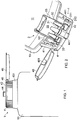
- a dosing dispenser device 1 fits on the neck of a plastic squeezable container 10.
- the dosing device 1 has a front cap component 4, being a one-piece moulding providing a front plate 42, a central outlet tube formation 44 with a forwardly projecting nozzle 441 and an outer securing skirt 41 with an internal thread 411 by means of which it fixes onto the container neck 101.
- An outer cover cap 45 is also provided, joining integrally to the rest of the cap component 4 through an integral butterfly hinge 46 so that the cap 45 is bistable in position, i.e. it tends either to be in fully shut or fully open position as shown.
- the underside of the cap 45 has an integral nozzle plug 451 which locks the outer nozzle 441 when the cap is shut.
- the second major component of the device is a control chamber or insert cylinder component 2.
- This is moulded from rigid plastics and consists essentially of a closed cylindrical side wall 25 defining an internal control chamber 29, and having around its front edge a connection structure in the form of an integral forward extension 21.
- the connection structure 21 comprises a continuous outer annulus 211 which plugs into the container neck 101 and has an outward end flange 212 which is trapped between the edge of the container neck and the underside of the cap web 42.
- the front edge of the chamber wall 25 has an outwardly flared portion 213 (seen best in Fig. 3 ) which in some circumferential regions connects through to the base of the locating ring 211, as seen in the portions indicated in Fig. 4 , described later), and at other circumferential regions stops short of the front so that a flow opening 23 is defined.
- FIG. 1 Behind the front plate 42 of the cap 4 the central outlet tube 44 projects rearwardly into the open front end of the control chamber 2.
- An obturator or control piston 3 is enclosed in the control chamber 29, and has a flat central disc 31 with a set of axially-projecting integrally-formed peripheral guide lugs 32 around its edge.
- the control piston 3 fits substantially - i.e. occupying nearly all the cross-section without being a tight fit - into the control chamber 29 so as to be freely slidable in it, between a forward position in which its central web surface 31 lies against and blocks the rear entrance to the outlet tube 44 (as seen in Fig. 2 ) and a rear position in which it lies against the rear wall 26 of the control chamber 2 (as seen in Fig. 4 ).
- the described cap and control chamber may be of polypropylene, and the piston of polyethylene, but other materials may be used.
- the outlet passage for liquid in the container exists from the container's interior space 11 and forwardly through the radial clearance between the control chamber 2 and the container neck 101, forward and in through the flow openings 23 to the space between the cap 4 and the control chamber 2 (and in front of the control piston 3), and finally inwardly through the rear entrance of the outlet tube 44 and out though the discharge nozzle 441.
- the rear wall 26 of the control chamber 2 has a set of small control openings 28.
- the dispensing closure comprises a one-piece integral valve and sealing insert 6, shown in one embodiment in Figs. 2 and 3 and in a slightly variant embodiment in Fig. 4 .
- It may be made of any suitable elastomer for the use in hand, but a polypropylene-based TPE is one suitable material.
- the elastomeric insert comprises a flat base web 61, with a rearward central sleeve 62 extending to an in-turned seal channel portion 64. The sleeve 62 fits closely around the polypropylene outlet tube 44 of the cap.
- the outlet tube has a rearward edge with reduced thickness 442, and the end of the elastomeric sleeve has a channel which fits over this so that the overall thickness is maintained, with a flush inner diameter.
- the rearward surface 641 of the elastomer channel constitutes an elastomeric sealing surface against which the web 31 of the piston 3 seals in use.
- the rearwardly-projecting sealing lip portion 63 of the elastomeric insert 6 is provided as a continuous annular formation (i.e. extending around the flow openings and also the supporting structures, for simplicity), and projects rearwardly to engage with resilient bias against the internal surface of the flared supporting regions 213 adjacent the flow openings 23.
- Figure 4 shows a variant in which the flat base web 61 of the elastomeric insert continues radially outwardly beyond the root of the sealing lip 63.
- This outer radial extension 615 is trapped, together with the support structure 21 of the control chamber 2, against the cap web 42 by the threading of the closure onto the container neck. This helps to keep the elastomer component 6 in position and may obviate the use of adhesives in assembly.
- valve flap 63 is differently disposed and oriented compared with the valve elements disclosed in the earlier application, its ability to prevent reverse flow is similar. However it has the additional property, by virtue of its biased resilient seal, of preventing premature dripping from the device after inversion of the container, before a dose is squeezed out. It has sufficient strength and resilience to withstand the head of liquid in the inverted container, and yields to provide the dispensing action only when the container is squeezed. Moreover, unlike the free valve elements described in the earlier application, it maintains its sealed condition in all orientations and avoids undesirable dripping or leakage in other situations too.
- the illustrated dispensers enable ready dispensing of two, three, four or more successive metered doses without the container needing to be righted from the inverted position.
- the device is adapted to give a dose size of between 10 and 50 ml, but this will vary from one product to another, and of course will to some extent depend on the viscosity of the product as well as on the selection of components in the dispenser.
- the aspects of the invention include the liquid dosing device itself, a closure assembly comprising such a device, a container such as a squeezable container with such a closure assembly fitted onto it, and a dispensing package comprising such a squeezable container, liquid product therein, and the liquid dosing dispenser/closure fitted to it.
Landscapes
- Physics & Mathematics (AREA)
- Fluid Mechanics (AREA)
- General Physics & Mathematics (AREA)
- Engineering & Computer Science (AREA)
- Mechanical Engineering (AREA)
- Closures For Containers (AREA)
- Containers And Packaging Bodies Having A Special Means To Remove Contents (AREA)
Claims (15)
- Dispositif de dosage pour distribuer des doses de liquide à partir d'un récipient (10), le dispositif (1) comprenant :un composant de capuchon de fermeture avant (4) se fixant sur une ouverture de goulot du récipient (10) et définissant une ouverture de décharge avant (441),une chambre de contrôle (2) positionnée derrière l'ouverture de décharge avant (441) pour faire saillie en arrière à l'intérieur du récipient, de sorte qu'un passage de sortie est défini, allant de l'intérieur du récipient vers l'avant au-delà ou autour de la chambre de contrôle jusqu'à l'ouverture de décharge avant (441), la chambre de contrôle (2) ayant une ou plusieurs ouvertures de contrôle arrière (28) pour introduire un écoulement limité de liquide de l'intérieur du récipient (1) dans la chambre de contrôle (2), etun obturateur (3) mobile dans la chambre de contrôle (2) et adapté pour avancer, pendant la distribution, sous l'influence du liquide qui s'écoule dans la chambre de contrôle (2) derrière ce dernier à travers l'ouverture (les ouvertures) de contrôle (28), jusqu'à une position de blocage où il bloque le passage de sortie afin de terminer une dose par la mise en prise avec une formation tubulaire s'étendant vers l'arrière (44) du composant de capuchon avant qui définit une partie du passage de sortie en face de l'obturateur (3) et a une périphérie annulaire arrière fournissant un siège dirigé vers l'arrière (442) qui entoure le passage de sortie et peut se mettre en prise grâce à une partie de blocage à l'avant de l'obturateur (3) dans la position de blocage,caractérisé en ce qu'un élément élastomère annulaire (64) est prévu autour de ladite périphérie annulaire arrière de la formation tubulaire (44) afin de former un joint d'étanchéité déformable de manière résiliente autour de sa région de mise en prise annulaire.
- Dispositif de dosage selon la revendication 1, dans lequel l'élément élastomère annulaire (64) a un évidement ou canal annulaire dirigé vers l'avant se montant sur la périphérie annulaire dirigée vers l'arrière (442) de la formation tubulaire (44).
- Dispositif de dosage selon la revendication 1 ou 2, dans lequel ledit élément élastomère annulaire (64) est compris dans un élément élastomère (6) comprenant également un manchon (62) qui s'étend vers l'avant à partir du siège (641) jusqu'à l'endroit où la formation tubulaire s'étendant vers l'arrière (44) rencontre une bande avant s'étendant de manière radiale (42) du composant de capuchon de fermeture (4) .
- Dispositif de dosage selon la revendication 3, dans lequel l'élément élastomère (6) comprend une partie d'extension radiale (61) qui s'étend radialement à partir du manchon (62) de part et d'autre de ladite bande avant (42).
- Dispositif de dosage selon l'une quelconque des revendications précédentes, dans lequel la partie de blocage (31) de l'obturateur (3) qui bloque le passage de sortie par la mise en prise avec ledit siège, est une surface sensiblement plate.
- Dispositif de dosage selon l'une quelconque des revendications précédentes, qui comprend une valve (63, 213) dans le passage de sortie pour empêcher l'écoulement en sens inverse.
- Dispositif de dosage selon la revendication 6, dans lequel la valve comprend un clapet de valve (63) sollicité de manière résiliente contre une partie de siège (213) correspondante.
- Dispositif de dosage selon la revendication 7, dans lequel le clapet de valve (63) est réalisé avec un matériau élastomère.
- Dispositif de dosage selon la revendication 7 ou 8, dans lequel le clapet de valve est un clapet de valve annulaire continu (63).
- Dispositif de dosage selon l'une quelconque des revendications 7 à 9, dans lequel un composant qui définit la chambre de contrôle (2) comprend également la structure de support s'étendant vers l'avant et/ou radialement vers l'extérieur afin de monter la chambre de contrôle (2) dans le goulot de récipient (101) ou le composant de capuchon de fermeture (4), et dans lequel le clapet de valve (63) est sollicité radialement vers l'extérieur contre ledit composant qui fournit ladite partie de siège.
- Dispositif de dosage selon l'une quelconque des revendications 8 à 12, dans lequel ledit élément élastomère annulaire (64) et le clapet de valve (63) sont compris dans un élément élastomère (6) unique.
- Dispositif de dosage selon la revendication 11, dans lequel l'élément élastomère (6) comprend une partie d'extension externe (615) piégée entre le composant de capuchon de fermeture (4) et le goulot de récipient (101) ou un autre composant du dispositif de dosage (1).
- Dispositif de dosage selon l'une quelconque des revendications précédentes, en combinaison avec ledit récipient (10) qui peut être comprimé de manière résiliente.
- Procédé pour distribuer des doses de liquide à partir d'un dispositif de dosage selon l'une quelconque des revendications précédentes, sur ledit récipient (10), le procédé comprenant l'étape consistant à retourner le récipient (10) pour provoquer l'écoulement de liquide à travers le passage de sortie, avec un écoulement limité de liquide à partir du récipient (10) dans la chambre de contrôle (2) à travers lesdites une ou plusieurs ouvertures de contrôle arrière (28) dans la paroi arrière (26) de la chambre de contrôle (2), l'obturateur (3) avançant jusqu'à la position de blocage où il bloque le passage de sortie afin de terminer la dose.
- Procédé selon la revendication 14, dans lequel le récipient est un récipient pouvant être comprimé, le procédé comprenant la libération d'une compression du récipient, facultativement avec le récipient retourné, pour recouvrer la forme du récipient et ramener l'obturateur (3) à l'arrière de la chambre de contrôle (2) de sorte qu'une autre dose peut être distribuée.
Applications Claiming Priority (2)
| Application Number | Priority Date | Filing Date | Title |
|---|---|---|---|
| GBGB0815881.8A GB0815881D0 (en) | 2008-09-01 | 2008-09-01 | Liquid dosing devices |
| PCT/GB2009/002106 WO2010023462A1 (fr) | 2008-09-01 | 2009-09-01 | Dispositifs de dosage de liquide |
Publications (2)
| Publication Number | Publication Date |
|---|---|
| EP2329231A1 EP2329231A1 (fr) | 2011-06-08 |
| EP2329231B1 true EP2329231B1 (fr) | 2020-04-08 |
Family
ID=39866051
Family Applications (1)
| Application Number | Title | Priority Date | Filing Date |
|---|---|---|---|
| EP09785034.1A Active EP2329231B1 (fr) | 2008-09-01 | 2009-09-01 | Dispositifs de dosage de liquide |
Country Status (4)
| Country | Link |
|---|---|
| US (1) | US8528795B2 (fr) |
| EP (1) | EP2329231B1 (fr) |
| GB (2) | GB0815881D0 (fr) |
| WO (1) | WO2010023462A1 (fr) |
Families Citing this family (25)
| Publication number | Priority date | Publication date | Assignee | Title |
|---|---|---|---|---|
| US9433960B2 (en) * | 2008-09-01 | 2016-09-06 | Rieke Corporation | Liquid dosing devices |
| GB0815881D0 (en) * | 2008-09-01 | 2008-10-08 | Rieke Corp | Liquid dosing devices |
| GB201000601D0 (en) | 2010-01-14 | 2010-03-03 | Rieke Corp | Pump dispensers |
| GB201011143D0 (en) | 2010-07-01 | 2010-08-18 | Rieke Corp | Dispensers |
| GB201011144D0 (en) | 2010-07-01 | 2010-08-18 | Rieke Corp | Dispensers |
| EP2444782B1 (fr) * | 2010-10-21 | 2019-01-16 | The Procter and Gamble Company | Appareil de dosage de liquides |
| ES2552249T1 (es) | 2012-04-17 | 2015-11-26 | The Procter & Gamble Company | Aparato dosificador de líquidos |
| GB201212042D0 (en) | 2012-07-05 | 2012-08-22 | Rieke Corp | Pump dispensers |
| US20140231462A1 (en) * | 2013-02-18 | 2014-08-21 | Gojo Industries, Inc. | Metered dose squeeze dispenser |
| ITVI20130297A1 (it) * | 2013-12-13 | 2015-06-14 | Taplast Srl | Dispositivo per l'erogazione di fluidi applicabile a contenitori e relativo sistema di erogazione. |
| US10071836B2 (en) * | 2014-04-16 | 2018-09-11 | Reckitt Benckiser (Brands) Limited | Dosing dispensing closure |
| CN106687219A (zh) * | 2014-09-04 | 2017-05-17 | 阿帕达弗赖翁有限公司 | 液体配量装置 |
| EP3088851A1 (fr) | 2015-04-28 | 2016-11-02 | Aptar Freyung GmbH | Dispositif de dosage de liquide |
| US10131473B2 (en) | 2015-02-23 | 2018-11-20 | Henkel IP & Holding GmbH | Inverted bottle dispensing systems and methods |
| EP3271259B1 (fr) * | 2015-03-19 | 2022-11-16 | Silgan Dispensing Systems Slatersville LLC | Fermeture de distribution à giclée pour concentré de boisson liquide |
| US10471452B2 (en) | 2015-06-29 | 2019-11-12 | Silgan Dispensing Systems Slatersville Llc | Measured dose dispensers and methods of using the same |
| US9555426B2 (en) * | 2015-06-29 | 2017-01-31 | Westrock Slatersville, Llc | Measured dose dispensers and methods of using the same |
| US10159998B2 (en) | 2015-06-29 | 2018-12-25 | Silgan Dispensing Systems Slatersville, Llc | Measured dose dispensers and methods of using the same |
| WO2017182972A1 (fr) | 2016-04-19 | 2017-10-26 | Flexidose | Distributeur doseur |
| MY193849A (en) * | 2016-06-24 | 2022-10-28 | Castrol Ltd | Fluid distribution and dispensing system |
| EP3315923B1 (fr) | 2016-10-25 | 2020-11-25 | The Procter & Gamble Company | Appareil de dosage de liquides |
| EP3315922B1 (fr) | 2016-10-25 | 2020-01-08 | The Procter & Gamble Company | Appareil de dosage de liquides |
| EP3315924B1 (fr) * | 2016-10-25 | 2021-07-14 | The Procter & Gamble Company | Appareil de dosage de liquides |
| US11629986B2 (en) | 2021-07-22 | 2023-04-18 | Curaleaf, Inc. | Squeeze doser with childproof cap |
| WO2023099790A1 (fr) | 2021-12-03 | 2023-06-08 | Rieke Packaging Systems Limited | Pompe de distribution à volume élevé à course axiale raccourcie |
Citations (1)
| Publication number | Priority date | Publication date | Assignee | Title |
|---|---|---|---|---|
| US5489044A (en) * | 1991-05-20 | 1996-02-06 | Hygiene-Technik Inc. | Method of preparing replaceable liquid soap reservoir |
Family Cites Families (76)
| Publication number | Priority date | Publication date | Assignee | Title |
|---|---|---|---|---|
| US2774517A (en) | 1955-09-19 | 1956-12-18 | James E Teegardin | Fluid dispenser device |
| US2919056A (en) * | 1956-02-20 | 1959-12-29 | Pressure Dispensers Inc | Liquid measuring device |
| US3379136A (en) | 1966-08-26 | 1968-04-23 | Diamond Int Corp | Liquid dispenser |
| JPS5620052Y2 (fr) | 1975-07-21 | 1981-05-13 | ||
| IL49703A (en) | 1976-06-02 | 1980-10-26 | Bron Dan | Pump for variable dosing |
| US4179051A (en) * | 1977-08-01 | 1979-12-18 | Ryder International Corporation | One-piece check valve for use in a fluid dispenser |
| US4371098A (en) | 1978-06-07 | 1983-02-01 | Yoshino Kogyosho Co., Ltd. | Atomizer usable in both normal and inverted orientations |
| EP0027431B1 (fr) | 1979-10-16 | 1984-07-11 | Duskin Franchise Kabushiki Kaisha | Distributeur, en particulier pour savon liquide |
| US4286736A (en) | 1980-02-20 | 1981-09-01 | Diamond International Corporation | Liquid Dispenser |
| US4364718A (en) | 1981-02-24 | 1982-12-21 | Internationale Octrooi Maatschappij "Octropa" Bv | Disposable pump for dispensing small metered amounts of liquid from a container and a control unit for operating said pump |
| JPS591377A (ja) | 1982-06-29 | 1984-01-06 | キヤニヨン株式会社 | デイスペンサ− |
| DE3225910A1 (de) | 1982-07-10 | 1984-01-12 | Pfeiffer Zerstäuber Vertriebsgesellschaft mbH & Co KG, 7760 Radolfzell | Zerstaeuber- oder dosierpumpe |
| US4519530A (en) * | 1983-02-25 | 1985-05-28 | Schmidt Gerhard S E | Self-closing dispenser |
| DE3513575A1 (de) | 1985-04-16 | 1986-10-16 | Ing. Erich Pfeiffer GmbH & Co KG, 7760 Radolfzell | Handbetaetigte ausgabeeinrichtung fuer medien |
| DE3517558A1 (de) | 1985-05-15 | 1986-11-20 | Ing. Erich Pfeiffer GmbH & Co KG, 7760 Radolfzell | Handbetaetigte ausgabeeinrichtung fuer medien |
| US4673109A (en) | 1985-10-18 | 1987-06-16 | Steiner Company, Inc. | Liquid soap dispensing system |
| US4775079A (en) | 1985-11-05 | 1988-10-04 | Hans Grothoff | Upright/inverted pump sprayer |
| US4811871A (en) * | 1986-12-17 | 1989-03-14 | The English Glass Company Limited | Liquid dosing device |
| IT1228787B (it) | 1989-03-31 | 1991-07-03 | Lumson Srl | Pompetta manuale per l'erogazione di liquidi o paste da flaconi. |
| DE3929064A1 (de) | 1989-06-29 | 1991-01-10 | Henkel Kgaa | Handbetaetigbarer fluessigkeitszerstaeuber zur abgabe dosierter mengen |
| US5165577A (en) | 1991-05-20 | 1992-11-24 | Heiner Ophardt | Disposable plastic liquid pump |
| US5282552A (en) | 1991-05-20 | 1994-02-01 | Hygiene-Technik Inc. | Disposable plastic liquid pump |
| US5975360A (en) | 1991-05-20 | 1999-11-02 | Ophardt; Heiner | Capped piston pump |
| US5676277A (en) | 1991-05-20 | 1997-10-14 | Ophardt; Heiner | Disposable plastic liquid pump |
| US5449094A (en) | 1992-05-18 | 1995-09-12 | Sofab | Dispenser with plunging sleeve |
| US6126042A (en) | 1992-05-22 | 2000-10-03 | Meshberg; Philip | Dispenser with inverted-dispensing feature and snap-on mounting cup |
| IT1256628B (it) | 1992-12-04 | 1995-12-12 | Distributore di sostanze fluide, con testa deformabile | |
| US5353969A (en) | 1993-10-13 | 1994-10-11 | Calmar Inc. | Invertible pump sprayer having spiral vent path |
| CA2102016C (fr) | 1993-10-29 | 1995-08-15 | Heiner Ophardt | Distributeur de savon liquide pour le remplacement simplifie pour du reservoir de savon |
| US5421492A (en) * | 1993-11-02 | 1995-06-06 | Glaxo Inc. | Metered aerosol dispensing apparatus and method of use thereof |
| US5445288A (en) | 1994-04-05 | 1995-08-29 | Sprintvest Corporation Nv | Liquid dispenser for dispensing foam |
| US5401148A (en) | 1994-04-15 | 1995-03-28 | Contico International, Inc. | Manually operated reciprocating liquid pump |
| JPH0811921A (ja) | 1994-06-23 | 1996-01-16 | Yoshino Kogyosho Co Ltd | 泡噴出容器 |
| AU715130B2 (en) | 1994-11-17 | 2000-01-20 | Yoshino Kogyosho Co., Ltd. | Container with pump for discharging bubbles |
| US5738250A (en) | 1997-04-07 | 1998-04-14 | Calmar Inc. | Liquid dispensing pump having water seal |
| DE19741957A1 (de) | 1997-09-23 | 1999-03-25 | Wischerath Josef Gmbh Co Kg | Verfahren zum Befüllen eines Spenders und Spender |
| US5904272A (en) * | 1997-11-12 | 1999-05-18 | Kaufman Products Inc. | Dispenser for liquids |
| US5988456A (en) | 1998-01-16 | 1999-11-23 | Laible; Rodney | Closed loop dispensing system |
| US6082586A (en) | 1998-03-30 | 2000-07-04 | Deb Ip Limited | Liquid dispenser for dispensing foam |
| US6045008A (en) | 1998-04-30 | 2000-04-04 | Calmar-Monturas, S.A. | Fluid pump dispenser |
| EP1092447B1 (fr) | 1999-10-14 | 2004-01-07 | Becton Dickinson and Company | Dispositif d'administration nasale avec buse de pulvérisation |
| GB0001119D0 (en) * | 2000-01-18 | 2000-03-08 | Wass Anthony C L | Improved liquid dosing device |
| FR2809776B1 (fr) | 2000-05-30 | 2002-12-06 | Rexam Smt | Pompe a membrane |
| US6343724B1 (en) | 2000-07-10 | 2002-02-05 | Hygiene Technik Inc. | Unitary one-way valve for fluid dispenser |
| FR2811644B1 (fr) | 2000-07-12 | 2002-09-06 | Oreal | Dispositif pour le conditionnement et la distribution dosee d'un produit liquide |
| US6612468B2 (en) | 2000-09-15 | 2003-09-02 | Rieke Corporation | Dispenser pumps |
| US6732958B2 (en) | 2000-10-24 | 2004-05-11 | 360 Enterprises | 360 degree rotational directional nozzle for trigger sprayers |
| US6516976B2 (en) | 2000-12-19 | 2003-02-11 | Kimberly-Clark Worldwide, Inc. | Dosing pump for liquid dispensers |
| US6543651B2 (en) | 2000-12-19 | 2003-04-08 | Kimberly-Clark Worldwide, Inc. | Self-contained viscous liquid dispenser |
| DE10109064A1 (de) * | 2001-02-24 | 2002-09-05 | Beiersdorf Ag | Öffnungssystem mit Rückbelüftungsmechanik |
| CA2341659C (fr) | 2001-03-20 | 2007-08-07 | Hygiene-Technik Inc. | Distributeur de liquide pour la distribution de mousse |
| US6540117B2 (en) | 2001-03-30 | 2003-04-01 | Kimberly-Clark Worldwide, Inc. | Dosing pump for liquid dispensers |
| CA2344185C (fr) | 2001-04-12 | 2011-03-15 | Heiner Ophardt | Bec pour distributrice de fluide |
| GB2385315B (en) * | 2002-01-15 | 2004-06-30 | Bespak Plc | Improvements in or relating to valves for dispensers |
| US6557736B1 (en) | 2002-01-18 | 2003-05-06 | Heiner Ophardt | Pivoting piston head for pump |
| CA2381868C (fr) | 2002-04-16 | 2009-09-01 | Hygiene-Technik Inc. | Dispositif casse-vide |
| GB0208806D0 (en) | 2002-04-17 | 2002-05-29 | Rieke Corp | Dispenser pumps |
| US7198175B2 (en) | 2002-04-26 | 2007-04-03 | Heiner Ophardt | Manual or pump assist fluid dispenser |
| JP4129811B2 (ja) * | 2002-04-30 | 2008-08-06 | 株式会社吉野工業所 | 注出容器 |
| AU2003238933A1 (en) | 2002-06-06 | 2003-12-22 | Kanfer, Joseph | Dip tube for use with a pump dispenser |
| DE50306841D1 (de) | 2003-02-21 | 2007-05-03 | Boehringer Ingelheim Micropart | Spender zum Abgeben eines flüssigen oder pastösen Mediums |
| US7004356B1 (en) | 2003-07-28 | 2006-02-28 | Joseph S. Kanfer | Foam producing pump with anti-drip feature |
| US7389893B2 (en) | 2003-09-10 | 2008-06-24 | Rieke Corporation | Inverted dispensing pump |
| US7325704B2 (en) | 2003-09-10 | 2008-02-05 | Rieke Corporation | Inverted dispensing pump with vent baffle |
| GB0326849D0 (en) * | 2003-11-18 | 2003-12-24 | Rieke Corp | Liquid dosing devices |
| US7654418B2 (en) | 2004-08-30 | 2010-02-02 | Rieke Corporation | Airless dispensing pump |
| US7367476B2 (en) | 2004-08-30 | 2008-05-06 | Rieke Corporation | Airless dispensing pump with tamper evidence features |
| FR2879567B1 (fr) | 2004-12-17 | 2007-01-26 | Seriplast Sa Sa | Flacon en matiere synthetique equipe d'une pompe |
| NL1030030C2 (nl) | 2005-04-20 | 2006-10-23 | Keltec B V | Afgifte-eenheid met verbeterde toevoer-afsluitmiddelen. |
| US20080308183A1 (en) | 2007-06-18 | 2008-12-18 | Law Brian R | Satellite dosing system |
| FR2927889B1 (fr) | 2008-02-26 | 2010-02-26 | Seriplast | Flacon destine a contenir un produit liquide ou pateux |
| FR2932171B1 (fr) | 2008-06-10 | 2010-08-20 | Rexam Dispensing Sys | Flacon de distribution comprenant une pompe integrant une membrane de purge |
| IT1391428B1 (it) | 2008-08-05 | 2011-12-23 | Lumson Spa | Dispositivo erogatore di sostanze fluide |
| GB0815881D0 (en) * | 2008-09-01 | 2008-10-08 | Rieke Corp | Liquid dosing devices |
| ITPD20090117A1 (it) | 2009-05-04 | 2010-11-05 | Euroflex Srl | Spruzzatore a mano per liquidi detergenti |
| EP2444782B1 (fr) * | 2010-10-21 | 2019-01-16 | The Procter and Gamble Company | Appareil de dosage de liquides |
-
2008
- 2008-09-01 GB GBGB0815881.8A patent/GB0815881D0/en not_active Ceased
-
2009
- 2009-09-01 WO PCT/GB2009/002106 patent/WO2010023462A1/fr active Application Filing
- 2009-09-01 GB GB0915272A patent/GB2463152A/en not_active Withdrawn
- 2009-09-01 EP EP09785034.1A patent/EP2329231B1/fr active Active
-
2011
- 2011-02-28 US US13/036,252 patent/US8528795B2/en active Active
Patent Citations (1)
| Publication number | Priority date | Publication date | Assignee | Title |
|---|---|---|---|---|
| US5489044A (en) * | 1991-05-20 | 1996-02-06 | Hygiene-Technik Inc. | Method of preparing replaceable liquid soap reservoir |
Also Published As
| Publication number | Publication date |
|---|---|
| GB0915272D0 (en) | 2009-10-07 |
| GB0815881D0 (en) | 2008-10-08 |
| GB2463152A (en) | 2010-03-10 |
| EP2329231A1 (fr) | 2011-06-08 |
| WO2010023462A1 (fr) | 2010-03-04 |
| US8528795B2 (en) | 2013-09-10 |
| US20110198371A1 (en) | 2011-08-18 |
Similar Documents
| Publication | Publication Date | Title |
|---|---|---|
| EP2329231B1 (fr) | Dispositifs de dosage de liquide | |
| US9433960B2 (en) | Liquid dosing devices | |
| US11413638B2 (en) | Dispenser pumps and dispensers | |
| WO2005049477A2 (fr) | Dispositifs de dosage de liquide | |
| JP3392755B2 (ja) | 改良されたポンプ手段を備えた液体製品またはペースト状製品のためのディスペンサ | |
| RU2272763C2 (ru) | Дозирующая система для выдачи продукта с удлиненным кончиком, содержащим открываемый давлением клапан | |
| CN108698064B (zh) | 分配器泵 | |
| US5725132A (en) | Dispenser with snap-fit container connection | |
| US6494346B2 (en) | Inverted package dispensing system | |
| WO2014126751A2 (fr) | Distributeur souple de dose mesurée | |
| US6422434B1 (en) | Dispenser pumps | |
| WO2012171708A1 (fr) | Bouchon doseur | |
| US4533069A (en) | Pump-type dispenser | |
| US20170276531A1 (en) | Liquid dosing device | |
| WO2006116312A2 (fr) | Distributeur a bec hermetique | |
| US20190031401A1 (en) | Dispensing systems and methods for using the same | |
| EP3088851A1 (fr) | Dispositif de dosage de liquide | |
| US20180299310A1 (en) | Liquid dosing devices | |
| WO2014086720A1 (fr) | Dispositif de conditionnement et distribution au moyen d'une pipette | |
| WO2014086719A1 (fr) | Dispositif de conditionnement et application au moyen d'une pipette | |
| US6968981B2 (en) | Dispenser for free-flowing products | |
| EP4114582B1 (fr) | Distributeur de réciprocité à volume élevé | |
| WO2022207072A1 (fr) | Ensemble pompe doté d'une protection |
Legal Events
| Date | Code | Title | Description |
|---|---|---|---|
| PUAI | Public reference made under article 153(3) epc to a published international application that has entered the european phase |
Free format text: ORIGINAL CODE: 0009012 |
|
| 17P | Request for examination filed |
Effective date: 20110328 |
|
| AK | Designated contracting states |
Kind code of ref document: A1 Designated state(s): AT BE BG CH CY CZ DE DK EE ES FI FR GB GR HR HU IE IS IT LI LT LU LV MC MK MT NL NO PL PT RO SE SI SK SM TR |
|
| AX | Request for extension of the european patent |
Extension state: AL BA RS |
|
| DAX | Request for extension of the european patent (deleted) | ||
| STAA | Information on the status of an ep patent application or granted ep patent |
Free format text: STATUS: EXAMINATION IS IN PROGRESS |
|
| 17Q | First examination report despatched |
Effective date: 20170518 |
|
| GRAP | Despatch of communication of intention to grant a patent |
Free format text: ORIGINAL CODE: EPIDOSNIGR1 |
|
| STAA | Information on the status of an ep patent application or granted ep patent |
Free format text: STATUS: GRANT OF PATENT IS INTENDED |
|
| INTG | Intention to grant announced |
Effective date: 20191024 |
|
| GRAS | Grant fee paid |
Free format text: ORIGINAL CODE: EPIDOSNIGR3 |
|
| GRAA | (expected) grant |
Free format text: ORIGINAL CODE: 0009210 |
|
| STAA | Information on the status of an ep patent application or granted ep patent |
Free format text: STATUS: THE PATENT HAS BEEN GRANTED |
|
| RAP1 | Party data changed (applicant data changed or rights of an application transferred) |
Owner name: RIEKE LLC |
|
| AK | Designated contracting states |
Kind code of ref document: B1 Designated state(s): AT BE BG CH CY CZ DE DK EE ES FI FR GB GR HR HU IE IS IT LI LT LU LV MC MK MT NL NO PL PT RO SE SI SK SM TR |
|
| REG | Reference to a national code |
Ref country code: GB Ref legal event code: FG4D |
|
| REG | Reference to a national code |
Ref country code: CH Ref legal event code: EP Ref country code: AT Ref legal event code: REF Ref document number: 1255014 Country of ref document: AT Kind code of ref document: T Effective date: 20200415 |
|
| REG | Reference to a national code |
Ref country code: IE Ref legal event code: FG4D |
|
| REG | Reference to a national code |
Ref country code: DE Ref legal event code: R096 Ref document number: 602009061680 Country of ref document: DE |
|
| REG | Reference to a national code |
Ref country code: NL Ref legal event code: MP Effective date: 20200408 |
|
| REG | Reference to a national code |
Ref country code: LT Ref legal event code: MG4D |
|
| PG25 | Lapsed in a contracting state [announced via postgrant information from national office to epo] |
Ref country code: LT Free format text: LAPSE BECAUSE OF FAILURE TO SUBMIT A TRANSLATION OF THE DESCRIPTION OR TO PAY THE FEE WITHIN THE PRESCRIBED TIME-LIMIT Effective date: 20200408 Ref country code: NO Free format text: LAPSE BECAUSE OF FAILURE TO SUBMIT A TRANSLATION OF THE DESCRIPTION OR TO PAY THE FEE WITHIN THE PRESCRIBED TIME-LIMIT Effective date: 20200708 Ref country code: GR Free format text: LAPSE BECAUSE OF FAILURE TO SUBMIT A TRANSLATION OF THE DESCRIPTION OR TO PAY THE FEE WITHIN THE PRESCRIBED TIME-LIMIT Effective date: 20200709 Ref country code: SE Free format text: LAPSE BECAUSE OF FAILURE TO SUBMIT A TRANSLATION OF THE DESCRIPTION OR TO PAY THE FEE WITHIN THE PRESCRIBED TIME-LIMIT Effective date: 20200408 Ref country code: FI Free format text: LAPSE BECAUSE OF FAILURE TO SUBMIT A TRANSLATION OF THE DESCRIPTION OR TO PAY THE FEE WITHIN THE PRESCRIBED TIME-LIMIT Effective date: 20200408 Ref country code: IS Free format text: LAPSE BECAUSE OF FAILURE TO SUBMIT A TRANSLATION OF THE DESCRIPTION OR TO PAY THE FEE WITHIN THE PRESCRIBED TIME-LIMIT Effective date: 20200808 Ref country code: PT Free format text: LAPSE BECAUSE OF FAILURE TO SUBMIT A TRANSLATION OF THE DESCRIPTION OR TO PAY THE FEE WITHIN THE PRESCRIBED TIME-LIMIT Effective date: 20200817 Ref country code: NL Free format text: LAPSE BECAUSE OF FAILURE TO SUBMIT A TRANSLATION OF THE DESCRIPTION OR TO PAY THE FEE WITHIN THE PRESCRIBED TIME-LIMIT Effective date: 20200408 |
|
| REG | Reference to a national code |
Ref country code: AT Ref legal event code: MK05 Ref document number: 1255014 Country of ref document: AT Kind code of ref document: T Effective date: 20200408 |
|
| PG25 | Lapsed in a contracting state [announced via postgrant information from national office to epo] |
Ref country code: LV Free format text: LAPSE BECAUSE OF FAILURE TO SUBMIT A TRANSLATION OF THE DESCRIPTION OR TO PAY THE FEE WITHIN THE PRESCRIBED TIME-LIMIT Effective date: 20200408 Ref country code: HR Free format text: LAPSE BECAUSE OF FAILURE TO SUBMIT A TRANSLATION OF THE DESCRIPTION OR TO PAY THE FEE WITHIN THE PRESCRIBED TIME-LIMIT Effective date: 20200408 Ref country code: BG Free format text: LAPSE BECAUSE OF FAILURE TO SUBMIT A TRANSLATION OF THE DESCRIPTION OR TO PAY THE FEE WITHIN THE PRESCRIBED TIME-LIMIT Effective date: 20200708 |
|
| REG | Reference to a national code |
Ref country code: DE Ref legal event code: R097 Ref document number: 602009061680 Country of ref document: DE |
|
| PG25 | Lapsed in a contracting state [announced via postgrant information from national office to epo] |
Ref country code: CZ Free format text: LAPSE BECAUSE OF FAILURE TO SUBMIT A TRANSLATION OF THE DESCRIPTION OR TO PAY THE FEE WITHIN THE PRESCRIBED TIME-LIMIT Effective date: 20200408 Ref country code: RO Free format text: LAPSE BECAUSE OF FAILURE TO SUBMIT A TRANSLATION OF THE DESCRIPTION OR TO PAY THE FEE WITHIN THE PRESCRIBED TIME-LIMIT Effective date: 20200408 Ref country code: DK Free format text: LAPSE BECAUSE OF FAILURE TO SUBMIT A TRANSLATION OF THE DESCRIPTION OR TO PAY THE FEE WITHIN THE PRESCRIBED TIME-LIMIT Effective date: 20200408 Ref country code: SM Free format text: LAPSE BECAUSE OF FAILURE TO SUBMIT A TRANSLATION OF THE DESCRIPTION OR TO PAY THE FEE WITHIN THE PRESCRIBED TIME-LIMIT Effective date: 20200408 Ref country code: EE Free format text: LAPSE BECAUSE OF FAILURE TO SUBMIT A TRANSLATION OF THE DESCRIPTION OR TO PAY THE FEE WITHIN THE PRESCRIBED TIME-LIMIT Effective date: 20200408 Ref country code: AT Free format text: LAPSE BECAUSE OF FAILURE TO SUBMIT A TRANSLATION OF THE DESCRIPTION OR TO PAY THE FEE WITHIN THE PRESCRIBED TIME-LIMIT Effective date: 20200408 Ref country code: ES Free format text: LAPSE BECAUSE OF FAILURE TO SUBMIT A TRANSLATION OF THE DESCRIPTION OR TO PAY THE FEE WITHIN THE PRESCRIBED TIME-LIMIT Effective date: 20200408 |
|
| PLBE | No opposition filed within time limit |
Free format text: ORIGINAL CODE: 0009261 |
|
| STAA | Information on the status of an ep patent application or granted ep patent |
Free format text: STATUS: NO OPPOSITION FILED WITHIN TIME LIMIT |
|
| PG25 | Lapsed in a contracting state [announced via postgrant information from national office to epo] |
Ref country code: SK Free format text: LAPSE BECAUSE OF FAILURE TO SUBMIT A TRANSLATION OF THE DESCRIPTION OR TO PAY THE FEE WITHIN THE PRESCRIBED TIME-LIMIT Effective date: 20200408 Ref country code: PL Free format text: LAPSE BECAUSE OF FAILURE TO SUBMIT A TRANSLATION OF THE DESCRIPTION OR TO PAY THE FEE WITHIN THE PRESCRIBED TIME-LIMIT Effective date: 20200408 |
|
| 26N | No opposition filed |
Effective date: 20210112 |
|
| PG25 | Lapsed in a contracting state [announced via postgrant information from national office to epo] |
Ref country code: MC Free format text: LAPSE BECAUSE OF FAILURE TO SUBMIT A TRANSLATION OF THE DESCRIPTION OR TO PAY THE FEE WITHIN THE PRESCRIBED TIME-LIMIT Effective date: 20200408 |
|
| REG | Reference to a national code |
Ref country code: CH Ref legal event code: PL |
|
| PG25 | Lapsed in a contracting state [announced via postgrant information from national office to epo] |
Ref country code: SI Free format text: LAPSE BECAUSE OF FAILURE TO SUBMIT A TRANSLATION OF THE DESCRIPTION OR TO PAY THE FEE WITHIN THE PRESCRIBED TIME-LIMIT Effective date: 20200408 |
|
| REG | Reference to a national code |
Ref country code: BE Ref legal event code: MM Effective date: 20200930 |
|
| PG25 | Lapsed in a contracting state [announced via postgrant information from national office to epo] |
Ref country code: LU Free format text: LAPSE BECAUSE OF NON-PAYMENT OF DUE FEES Effective date: 20200901 |
|
| PG25 | Lapsed in a contracting state [announced via postgrant information from national office to epo] |
Ref country code: BE Free format text: LAPSE BECAUSE OF NON-PAYMENT OF DUE FEES Effective date: 20200930 Ref country code: CH Free format text: LAPSE BECAUSE OF NON-PAYMENT OF DUE FEES Effective date: 20200930 Ref country code: IE Free format text: LAPSE BECAUSE OF NON-PAYMENT OF DUE FEES Effective date: 20200901 Ref country code: LI Free format text: LAPSE BECAUSE OF NON-PAYMENT OF DUE FEES Effective date: 20200930 |
|
| PGFP | Annual fee paid to national office [announced via postgrant information from national office to epo] |
Ref country code: DE Payment date: 20211027 Year of fee payment: 13 Ref country code: GB Payment date: 20211027 Year of fee payment: 13 |
|
| PGFP | Annual fee paid to national office [announced via postgrant information from national office to epo] |
Ref country code: IT Payment date: 20211021 Year of fee payment: 13 Ref country code: FR Payment date: 20211025 Year of fee payment: 13 |
|
| PG25 | Lapsed in a contracting state [announced via postgrant information from national office to epo] |
Ref country code: TR Free format text: LAPSE BECAUSE OF FAILURE TO SUBMIT A TRANSLATION OF THE DESCRIPTION OR TO PAY THE FEE WITHIN THE PRESCRIBED TIME-LIMIT Effective date: 20200408 Ref country code: MT Free format text: LAPSE BECAUSE OF FAILURE TO SUBMIT A TRANSLATION OF THE DESCRIPTION OR TO PAY THE FEE WITHIN THE PRESCRIBED TIME-LIMIT Effective date: 20200408 Ref country code: CY Free format text: LAPSE BECAUSE OF FAILURE TO SUBMIT A TRANSLATION OF THE DESCRIPTION OR TO PAY THE FEE WITHIN THE PRESCRIBED TIME-LIMIT Effective date: 20200408 |
|
| PG25 | Lapsed in a contracting state [announced via postgrant information from national office to epo] |
Ref country code: MK Free format text: LAPSE BECAUSE OF FAILURE TO SUBMIT A TRANSLATION OF THE DESCRIPTION OR TO PAY THE FEE WITHIN THE PRESCRIBED TIME-LIMIT Effective date: 20200408 |
|
| REG | Reference to a national code |
Ref country code: DE Ref legal event code: R119 Ref document number: 602009061680 Country of ref document: DE |
|
| GBPC | Gb: european patent ceased through non-payment of renewal fee |
Effective date: 20220901 |
|
| PG25 | Lapsed in a contracting state [announced via postgrant information from national office to epo] |
Ref country code: FR Free format text: LAPSE BECAUSE OF NON-PAYMENT OF DUE FEES Effective date: 20220930 Ref country code: DE Free format text: LAPSE BECAUSE OF NON-PAYMENT OF DUE FEES Effective date: 20230401 |
|
| PG25 | Lapsed in a contracting state [announced via postgrant information from national office to epo] |
Ref country code: IT Free format text: LAPSE BECAUSE OF NON-PAYMENT OF DUE FEES Effective date: 20220901 Ref country code: GB Free format text: LAPSE BECAUSE OF NON-PAYMENT OF DUE FEES Effective date: 20220901 |