EP2329231B1 - Liquid dosing devices - Google Patents
Liquid dosing devices Download PDFInfo
- Publication number
- EP2329231B1 EP2329231B1 EP09785034.1A EP09785034A EP2329231B1 EP 2329231 B1 EP2329231 B1 EP 2329231B1 EP 09785034 A EP09785034 A EP 09785034A EP 2329231 B1 EP2329231 B1 EP 2329231B1
- Authority
- EP
- European Patent Office
- Prior art keywords
- container
- control chamber
- dosing device
- obturator
- outlet passage
- Prior art date
- Legal status (The legal status is an assumption and is not a legal conclusion. Google has not performed a legal analysis and makes no representation as to the accuracy of the status listed.)
- Active
Links
Images

Classifications
-
- G—PHYSICS
- G01—MEASURING; TESTING
- G01F—MEASURING VOLUME, VOLUME FLOW, MASS FLOW OR LIQUID LEVEL; METERING BY VOLUME
- G01F13/00—Apparatus for measuring by volume and delivering fluids or fluent solid materials, not provided for in the preceding groups
- G01F13/006—Apparatus for measuring by volume and delivering fluids or fluent solid materials, not provided for in the preceding groups measuring volume in function of time
-
- B—PERFORMING OPERATIONS; TRANSPORTING
- B67—OPENING, CLOSING OR CLEANING BOTTLES, JARS OR SIMILAR CONTAINERS; LIQUID HANDLING
- B67D—DISPENSING, DELIVERING OR TRANSFERRING LIQUIDS, NOT OTHERWISE PROVIDED FOR
- B67D3/00—Apparatus or devices for controlling flow of liquids under gravity from storage containers for dispensing purposes
- B67D3/0041—Apparatus or devices for controlling flow of liquids under gravity from storage containers for dispensing purposes with provisions for metering the liquid to be dispensed
-
- G—PHYSICS
- G01—MEASURING; TESTING
- G01F—MEASURING VOLUME, VOLUME FLOW, MASS FLOW OR LIQUID LEVEL; METERING BY VOLUME
- G01F11/00—Apparatus requiring external operation adapted at each repeated and identical operation to measure and separate a predetermined volume of fluid or fluent solid material from a supply or container, without regard to weight, and to deliver it
- G01F11/02—Apparatus requiring external operation adapted at each repeated and identical operation to measure and separate a predetermined volume of fluid or fluent solid material from a supply or container, without regard to weight, and to deliver it with measuring chambers which expand or contract during measurement
- G01F11/04—Apparatus requiring external operation adapted at each repeated and identical operation to measure and separate a predetermined volume of fluid or fluent solid material from a supply or container, without regard to weight, and to deliver it with measuring chambers which expand or contract during measurement of the free-piston type
-
- G—PHYSICS
- G01—MEASURING; TESTING
- G01F—MEASURING VOLUME, VOLUME FLOW, MASS FLOW OR LIQUID LEVEL; METERING BY VOLUME
- G01F11/00—Apparatus requiring external operation adapted at each repeated and identical operation to measure and separate a predetermined volume of fluid or fluent solid material from a supply or container, without regard to weight, and to deliver it
- G01F11/10—Apparatus requiring external operation adapted at each repeated and identical operation to measure and separate a predetermined volume of fluid or fluent solid material from a supply or container, without regard to weight, and to deliver it with measuring chambers moved during operation
- G01F11/26—Apparatus requiring external operation adapted at each repeated and identical operation to measure and separate a predetermined volume of fluid or fluent solid material from a supply or container, without regard to weight, and to deliver it with measuring chambers moved during operation wherein the measuring chamber is filled and emptied by tilting or inverting the supply vessel, e.g. bottle-emptying apparatus
- G01F11/262—Apparatus requiring external operation adapted at each repeated and identical operation to measure and separate a predetermined volume of fluid or fluent solid material from a supply or container, without regard to weight, and to deliver it with measuring chambers moved during operation wherein the measuring chamber is filled and emptied by tilting or inverting the supply vessel, e.g. bottle-emptying apparatus for liquid or semi-liquid
- G01F11/263—Apparatus requiring external operation adapted at each repeated and identical operation to measure and separate a predetermined volume of fluid or fluent solid material from a supply or container, without regard to weight, and to deliver it with measuring chambers moved during operation wherein the measuring chamber is filled and emptied by tilting or inverting the supply vessel, e.g. bottle-emptying apparatus for liquid or semi-liquid with valves
Description
- This invention has to do with devices adapted for dispensing metered doses of liquid from a container, and containers incorporating such devices, and methods of using them. In preferred embodiments the devices are used in, or adapted for use in, squeezable containers, especially resiliently-shape-recovering squeezable containers. A preferred field of use is that of containers for domestic or household use, containing detergents or other cleaning preparations, fabric conditioners, or liquid foods such as sauces.
- Particularly, the invention is concerned with liquid dosing devices of a known kind (referred to below as "the kind described") having an outlet passage leading to a front discharge opening, past or around a control chamber positioned behind the front discharge opening and having one or more rear control openings to admit a restricted flow of liquid from the container interior into the control chamber. An obturator such as a sliding piston is movable in the control chamber and adapted to advance, during dispensing, under the influence of liquid flowing into the control chamber behind it through the control opening(s). When the obturator has advanced sufficiently it blocks the outlet passage to terminate the dose. Usually the outlet path of the liquid leads from the container interior forwardly past outside the control chamber and then radially inwardly, around (or through) the front peripheral part of the control chamber wall, to in front of the obturator and to the discharge opening. This front part of the chamber wall may have one or more circumferentially-distributed flow openings for this purpose. The discharge opening is typically axial or central at the front of the device. The part of the passage leading immediately to it is desirably defined by a tubular extension, projecting rearwardly towards the obturator and providing a seat against which the front of the obturator rests to block the passage.
- See for example our
EP-A-0274256 describing how the outside of the tubular extension can also serve to guide the liquid flow rearwardly towards the obturator piston to control its rate of advance. - Devices of the kind described have an advantage, compared with dispensers using a metering chamber adjacent the container mouth, in that the volume dispensed is not swept out or held in the dosing device itself. It is possible to achieve a large dose without a large device.
- However there are issues with speed and convenience. Obturators may be slow to recover position, and the dispenser needs to be returned to an upright position to create a new dose or restart the mechanism.
- Our
WO2005/049477 has two proposals addressing such issues. - One proposal provides a dump valve arrangement at the back of the control chamber. Such a dump valve - also discussed in one version in
EP-A-0274256 - is operable to close during dispensing - under gravity and/or forward fluid pressure - so that liquid enters the control chamber only through the control opening(s). The dump valve opens after dispensing - under gravity and/or reverse fluid pressure - so that liquid can escape from the control chamber more rapidly than if the only escape route were through the control opening(s). - The second proposal of
WO2005/049477 , implemented with a resiliently squeezable container, provides a unidirectional valve inhibiting reverse flow in the outlet passage upstream of the obturator's blocking position. On recovery of shape of the container after squeezing out a dose, the movable element of the valve - disclosed as a free annulus or a radial flap - is urged onto its seat by the reverse fluid pressure and prevents liquid from returning to the container interior by way of the outlet passage. Instead it flows back into the container from the control chamber space behind the obturator i.e. through the control opening(s), and/or dump valve opening if present. This speeds return of the obturator to its retracted position so that another dose can be dispensed, and desirably can clear the control chamber and re-initiate the obturator even while the container is inverted (typically, with the front of the dosing device and the discharge opening facing down). Repeated doses can then be dispensed without needing to right the container between doses. The forced retraction of the obturator also draws liquid back out of the discharge opening area (nozzle tube), reducing dripping after dispensing. - We have found that these previous proposals still leave something to be desired in dispensing performance in respect of clean termination of the dose, and in respect of repeated dosing while inverted. The present proposals address these issues independently and in combination, as well as (in preferred embodiments) providing convenient manufacturing solutions for the components concerned.
- In the present proposals, in a device of the kind described, a surface of the device defining a part of the outlet passage in front of the obturator presents a rearwardly-directed seat, surrounding the outlet passage and engageable by a blocking portion at the front of the obturator in its advanced position, around an annular engagement region, so as to block the outlet passage as mentioned previously. The proposal is that the surface of the seat comprises a resiliently deformable sealing material, specifically elastomer material, at least around the respective annular engagement region thereof.
- Specifically, as set out in
claim 1, the invention provides a dosing device for dispensing metered doses of liquid from a container, the device comprising
a front closure cap component securing onto a neck opening of the container and defining a front discharge opening,
a control chamber positioned behind the front discharge opening to project back inside the container, such that an outlet passage is defined leading from the container interior forward past or around the control chamber to the front discharge opening, the control chamber having one or more rear control openings to admit a restricted flow of liquid from the container interior into the control chamber, and
an obturator movable in the control chamber and adapted to advance forward, during dispensing, under the influence of liquid flowing into the control chamber behind it through the control opening(s), to a blocking position where it blocks the outlet passage to terminate a dose by engagement with a rearwardly-extending tubular formation of the front cap component which defines part of the outlet passage in front of the obturator and has a rear annular periphery providing a rearwardly-directed seat, which surrounds the outlet passage and is engageable by a blocking portion at the front of the obturator in the blocking position,
characterised in that an annular elastomeric element is provided around said rear annular periphery of the tubular formation to form a resiliently deformable seal around an annular engagement region thereof. - By this means we find that we can achieve a marked improvement in dosing performance, so that at the end of a dose, the flow through the discharge opening is cut off suddenly and completely with little or no subsequent dripping.
- The seat against which the obturator seals is the annular periphery of a rearwardly-extending tubular formation, typically a cylindrical formation. The corresponding blocking portion of the obturator may be a substantially flat surface, e.g. a substantially flat piston front face. This minimises the contact area and maximises the perpendicularity of the contact surface to the contact movement, reducing wedging and sticking. Desirably the obturator and tubular outlet formation are of relatively rigid plastics material, the resiliently deformable (elastomeric) material for the seal being provided as a surface covering on one or both of these. An elastomeric element forming an annulus around the rear edge of the tubular outlet formation can be connected by some suitable means (or coated) onto the underlying plastics material of the tubular formation. Desirably the elastomeric element is or includes an annular part with a forwardly-directed annular recess or channel fitting onto the rearwardly-directed annular periphery of the tubular outlet formation.
- The resiliently deformable component may be attached to the tubular outlet formation by any suitable means, e.g. interference fit, adhesive, interlock formation or integral moulding such as "two shot" moulding, perhaps with form interlock.
- In one preferred embodiment a sleeve of elastomeric covering extends forwardly from the sealing seat, around the tubular outlet formation, to where this formation meets the radially-extending front web of the container closure in which the device is comprised, and the elastomeric member there desirably extends out radially from the sleeve across this web. This radial extension portion may optionally be trapped by engagement by other members of the device, or between the container neck and part of the device, for additional security.
- An optional feature of our proposals relates to the feature of a unidirectional anti-reverse valve in the outlet passage, an idea disclosed as such in
WO2005/049477 . In this feature we may provide a unidirectional valve of this type which is resiliently biased against the corresponding seat portion(s), i.e. towards the closed condition. Desirably, this is by means of the valve comprising a flap member of elastomeric material, such as a rubber or thermoplastic elastomer (TPE). The elastomeric valve element may be deformed relative to its free shape when assembled into the device, so that the flap thereof is biased against its counter-surface. - The advantage of this is as follows. As in the proposal of
WO2005/049477 above, it prevents reverse flow along the outlet passage when the container - which may still be inverted - recovers its volume after dispensing a dose. This speeds retraction of the obturator, and may enable dispensing of two or more doses without righting the container in between. Additionally, however, the resilient bias of the sealing element to its closed condition resists pressure from the body of liquid in the container when the container is inverted. Dimensions, material and initial bias deformation of the sealing element may be selected so that it will open the outer passage only when a predetermined threshold pressure, corresponding for example to a typical static pressure head associated with a container full of the intended liquid product in the inverted container, is exceeded e.g. by a pressure corresponding to a typical vigorous manual squeeze of the inverted container. Moreover by this simple expedient the valve element takes on the additional function of preventing unwanted preliminary dripping or trickling from the container if there is a delay between inverting it and squeezing it. - This feature therefore contributes to achieving a cleanly-defined dose.
- Moreover, since each of the invention and the optional feature is preferably embodied using an elastomeric element - a static seal element and a valve flap element respectively - a particularly preferred embodiment of our proposal combines these into a single elastomeric element. It may comprise a central annulus forming the seal on the rear edge of the tubular outlet formation and, radially spaced outwardly therefrom, an integral flap formation (e.g. a continuous annulus, or segment(s) corresponding to one or more circumferentially-localised flow openings) which spans the corresponding portion of the outlet passage.
- Desirably the valve operates adjacent (at, adjacent or through) a front periphery of the control chamber and has a sealing edge engageable with a component bounding the outer passage at that point so that in its rest condition it blocks the outer passage at that position.
- There may be plural flow openings, e.g. circumferentially distributed between formations which support the control chamber component. These may be controlled by respective portions or segments of the mentioned valve member, or more conveniently by a continuous annular valve flap since this need not be rotationally aligned during assembly.
- In a preferred embodiment the valve flap projects generally rearwardly, and is biased radially outwardly against a corresponding opposed sealing region (seat portion), e.g. on the inside of a component which defines a control chamber and also has supporting structure extending forwardly and/or radially outwardly to mount the control chamber in the container neck, with one or more flow openings at the front of this structure.
- The elastomeric element may therefore conveniently comprise a front layer or web with a central rearward sleeve carrying the seal and, spaced radially outwardly from it, one or more rearwardly-projecting sealing skirts constituting the valve flap(s). Such a valve flap may be outwardly radially divergent at least in its free condition. Optionally also a further radially outwardly extending portion of the front web or layer is provided, to be trapped between components of the container closure to hold the elastomeric element securely in position.
- By these means, a device otherwise corresponding substantially to the known devices can readily be adapted to significantly improve its dosing performance, reducing dripping or leakage both before and after each dose and/or enabling repeated dosing in the inverted condition if desired.
- In other respects, the general conformation of the closure elements (e.g. control chamber, obturator, cap, container) may be as described in the earlier applications acknowledged previously. The device may be provided on a neck at the top of an invertible container. The discharge opening may be directed upwardly, e.g. vertically upwardly, when the container stands upright on its base. The movement direction of the obturator is desirably generally coaxial with the neck, and desirably generally coaxial with the external discharge opening.
- In a preferred version, as mentioned above, the outlet passage begins with substantially the entire space surrounding the control chamber - e.g. through a clearance between this chamber (which is typically cylindrical) and a wider container neck in which it is mounted, preferably coaxially - and leads through or around the front edge of the control chamber via one or more circumferentially-distributed openings so as to provide a suitable cross-section of flow, and then inwardly to a central discharge outlet this outlet having said rearwardly-extending tube formation.
- In preferred constructions the control chamber and its connection structure are a single moulded unit, connecting to the front cap component of the device which also comprises integrally (or mounts) the discharge outlet formation, and includes means such as a screw thread or snap ribs for securing it onto/into a container neck opening, with the control chamber projecting back inside the container neck with lateral or radial clearance for the outflow of product past it. Desirably an outer cover cap for the discharge opening is included. The cover cap may include a plug closure for the discharge opening. The cover cap may be integrally hinged to the mentioned front cap component. It will be understood that the main web of the front cap component may provide the rear surface against which the radial web of the preferred elastomeric component may lie.
- The form of the obturator is not particularly limited, and all of the general and specific options proposed in
EP-A-0 274 256 andWO 2005/049477 are available. - The squeezable container may be of any (e.g. well-known) type, shape and material.
- The components of the dosing closure device are typically moulded plastics components, joining by snap, press or screw engagements without requiring discrete fasteners. The device is suitable for implementation in mass-produced containers, e.g. for household products or food products. In this respect, TPE is desirable for use as the elastomeric components because many TPEs have high compatibility with household or indeed food use.
- The control chamber may or may not be provided with a dump valve of the type described in our above-mentioned earlier applications for further facilitating emptying of the chamber after dosing.
- Further aspects are corresponding methods of dispensing liquid, especially with repeated dosing in the inverted position as described, as set out in claims 14 and 15.
- Examples of the present proposals are now described with reference to the accompanying drawings in which:
-
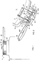
Fig. 1 is an elevation of the upper part of a squeezable container, showing the external appearance of a dosing device of the present type; -
Fig. 2 is an axial section showing the dosing device in an inverted position; -
Fig. 3 is an axial cross-sectional detail of theFig. 2 device, showing operating portions of an elastomeric insert, and -
Fig. 4 is an axial section showing a variant construction of the elastomeric insert. - With reference to
Figs. 1 and 2 , adosing dispenser device 1 fits on the neck of a plasticsqueezable container 10. Thedosing device 1 has afront cap component 4, being a one-piece moulding providing afront plate 42, a centraloutlet tube formation 44 with a forwardly projectingnozzle 441 and anouter securing skirt 41 with aninternal thread 411 by means of which it fixes onto thecontainer neck 101. Anouter cover cap 45 is also provided, joining integrally to the rest of thecap component 4 through anintegral butterfly hinge 46 so that thecap 45 is bistable in position, i.e. it tends either to be in fully shut or fully open position as shown. The underside of thecap 45 has anintegral nozzle plug 451 which locks theouter nozzle 441 when the cap is shut. - The second major component of the device is a control chamber or insert cylinder component 2. This is moulded from rigid plastics and consists essentially of a closed
cylindrical side wall 25 defining aninternal control chamber 29, and having around its front edge a connection structure in the form of an integralforward extension 21. Theconnection structure 21 comprises a continuousouter annulus 211 which plugs into thecontainer neck 101 and has anoutward end flange 212 which is trapped between the edge of the container neck and the underside of thecap web 42. Inwardly of this, the front edge of thechamber wall 25 has an outwardly flared portion 213 (seen best inFig. 3 ) which in some circumferential regions connects through to the base of the locatingring 211, as seen in the portions indicated inFig. 4 , described later), and at other circumferential regions stops short of the front so that a flow opening 23 is defined. Here there are threeequidistant flow openings 23 but this is not critical. - Behind the
front plate 42 of thecap 4 thecentral outlet tube 44 projects rearwardly into the open front end of the control chamber 2. An obturator orcontrol piston 3 is enclosed in thecontrol chamber 29, and has a flatcentral disc 31 with a set of axially-projecting integrally-formed peripheral guide lugs 32 around its edge. Thecontrol piston 3 fits substantially - i.e. occupying nearly all the cross-section without being a tight fit - into thecontrol chamber 29 so as to be freely slidable in it, between a forward position in which itscentral web surface 31 lies against and blocks the rear entrance to the outlet tube 44 (as seen inFig. 2 ) and a rear position in which it lies against therear wall 26 of the control chamber 2 (as seen inFig. 4 ). - The described cap and control chamber may be of polypropylene, and the piston of polyethylene, but other materials may be used.
- Thus, the outlet passage for liquid in the container exists from the container's
interior space 11 and forwardly through the radial clearance between the control chamber 2 and thecontainer neck 101, forward and in through theflow openings 23 to the space between thecap 4 and the control chamber 2 (and in front of the control piston 3), and finally inwardly through the rear entrance of theoutlet tube 44 and out though thedischarge nozzle 441. - As described in the earlier applications, the
rear wall 26 of the control chamber 2 has a set ofsmall control openings 28. - Additionally, the dispensing closure comprises a one-piece integral valve and sealing insert 6, shown in one embodiment in
Figs. 2 and3 and in a slightly variant embodiment inFig. 4 . It may be made of any suitable elastomer for the use in hand, but a polypropylene-based TPE is one suitable material. In the illustrated embodiment, the elastomeric insert comprises aflat base web 61, with a rearwardcentral sleeve 62 extending to an in-turnedseal channel portion 64. Thesleeve 62 fits closely around thepolypropylene outlet tube 44 of the cap. The outlet tube has a rearward edge with reducedthickness 442, and the end of the elastomeric sleeve has a channel which fits over this so that the overall thickness is maintained, with a flush inner diameter. Therearward surface 641 of the elastomer channel constitutes an elastomeric sealing surface against which theweb 31 of thepiston 3 seals in use. - The rearwardly-projecting
sealing lip portion 63 of the elastomeric insert 6 is provided as a continuous annular formation (i.e. extending around the flow openings and also the supporting structures, for simplicity), and projects rearwardly to engage with resilient bias against the internal surface of the flared supportingregions 213 adjacent theflow openings 23. -
Figure 4 shows a variant in which theflat base web 61 of the elastomeric insert continues radially outwardly beyond the root of the sealinglip 63. This outerradial extension 615 is trapped, together with thesupport structure 21 of the control chamber 2, against thecap web 42 by the threading of the closure onto the container neck. This helps to keep the elastomer component 6 in position and may obviate the use of adhesives in assembly. - In use, the general dosing action is as described above and in
WO2005/049477 , and need not be repeated here. It will be noted that, while thevalve flap 63 is differently disposed and oriented compared with the valve elements disclosed in the earlier application, its ability to prevent reverse flow is similar. However it has the additional property, by virtue of its biased resilient seal, of preventing premature dripping from the device after inversion of the container, before a dose is squeezed out. It has sufficient strength and resilience to withstand the head of liquid in the inverted container, and yields to provide the dispensing action only when the container is squeezed. Moreover, unlike the free valve elements described in the earlier application, it maintains its sealed condition in all orientations and avoids undesirable dripping or leakage in other situations too. - Additionally, the improved sealing engagement between the
elastomeric surface 641 of the outlet tube and the front face of thepiston web 31 gives an improved cut-off of flow at the end of each dispenser action. - As a result, we find that the illustrated dispensers enable ready dispensing of two, three, four or more successive metered doses without the container needing to be righted from the inverted position.
- We prefer that the device is adapted to give a dose size of between 10 and 50 ml, but this will vary from one product to another, and of course will to some extent depend on the viscosity of the product as well as on the selection of components in the dispenser.
- The aspects of the invention include the liquid dosing device itself, a closure assembly comprising such a device, a container such as a squeezable container with such a closure assembly fitted onto it, and a dispensing package comprising such a squeezable container, liquid product therein, and the liquid dosing dispenser/closure fitted to it.
- The skilled reader will appreciate that the invention is not necessarily limited to the features of the described embodiments and other embodiments may be made and used on the basis of the general teachings herein as defined by the appended claims.
Claims (15)
- A dosing device for dispensing metered doses of liquid from a container (10), the device (1) comprising
a front closure cap component (4) securing onto a neck opening of the container (10) and defining a front discharge opening (441),
a control chamber (2) positioned behind the front discharge opening (441) to project back inside the container, such that an outlet passage is defined leading from the container interior forward past or around the control chamber to the front discharge opening (441), the control chamber (2) having one or more rear control openings (28) to admit a restricted flow of liquid from the container interior (11) into the control chamber (2), and
an obturator (3) movable in the control chamber (2) and adapted to advance forward, during dispensing, under the influence of liquid flowing into the control chamber (2) behind it through the control opening(s) (28), to a blocking position where it blocks the outlet passage to terminate a dose by engagement with a rearwardly-extending tubular formation (44) of the front cap component which defines part of the outlet passage in front of the obturator (3) and has a rear annular periphery providing a rearwardly-directed seat (442), which surrounds the outlet passage and is engageable by a blocking portion at the front of the obturator (3) in the blocking position,
characterised in that an annular elastomeric element (64) is provided around said rear annular periphery of the tubular formation (44) to form a resiliently deformable seal around an annular engagement region thereof. - A dosing device according to claim 1 wherein the annular elastomeric element (64) has a forwardly-directed annular recess or channel fitting onto said rearwardly-directed annular periphery (442) of the tubular formation (44) .
- A dosing device according to claim 1 or 2 wherein said annular elastomeric element (64) is comprised in an elastomeric element (6) also comprising a sleeve (62) that extends forwardly from the seat (641) to where the rearwardly-extending tubular formation (44) meets a radially-extending front web (42) of the closure cap component (4).
- A dosing device according to claim 3 wherein the elastomeric element (6) comprises a radial extension portion (61) that extends out radially from the sleeve (62) across said front web (42).
- A dosing device according to any one of the preceding claims in which the blocking portion (31) of the obturator (3), which blocks the outlet passage by engagement with said seat, is a substantially flat surface.
- A dosing device according to any one of the preceding claims which comprises a valve (63,213) in the outlet passage to prevent reverse flow.
- A dosing device according to claim 6 wherein the valve comprises a valve flap (63) resiliently biased against a corresponding seat portion (213).
- A dosing device according to claim 7 wherein the valve flap (63) is of elastomeric material.
- A dosing device according to claim 7 or 8 wherein the valve flap is a continuous annular valve flap (63).
- A dosing device according to any one of claims 7 to 9 wherein a component which defines the control chamber (2) also comprises supporting structure extending forwardly and/or radially outwardly to mount the control chamber (2) in the container neck (101) or closure cap component (4), and wherein the valve flap (63) is biased radially outwardly against said component which provides said seat portion.
- A dosing device according to any one of claims 8 to 12 wherein said annular elastomeric element (64) and the valve flap (63) are comprised in a single elastomeric element (6).
- A dosing device according to claim 11 wherein the elastomeric element (6) comprises an outer extension portion (615) trapped between the closure cap component (4) and the container neck (101) or another component of the dosing device (1).
- A dosing device according to any one of the preceding claims in combination with a said container (10) which is resiliently squeezable.
- A method of dispensing metered doses of liquid from a dosing device according to any one of the preceding claims on a said container (10), the method comprising inverting the container (10) to cause the flow of liquid through the outlet passage, with a restricted flow of liquid from the container (10) into the control chamber (2) through said one or more rear control openings (28) in the rear wall (26) of the control chamber (2), the obturator (3) advancing to the blocking position where it blocks the outlet passage to terminate the dose.
- A method according to claim 14 in which the container is a squeezable container, the method comprising releasing a squeeze of the container, optionally with the container inverted, to recover the container shape and urge the obturator (3) back to the rear of the control chamber (2) so that another dose can be dispensed.
Applications Claiming Priority (2)
| Application Number | Priority Date | Filing Date | Title |
|---|---|---|---|
| GBGB0815881.8A GB0815881D0 (en) | 2008-09-01 | 2008-09-01 | Liquid dosing devices |
| PCT/GB2009/002106 WO2010023462A1 (en) | 2008-09-01 | 2009-09-01 | Liquid dosing devices |
Publications (2)
| Publication Number | Publication Date |
|---|---|
| EP2329231A1 EP2329231A1 (en) | 2011-06-08 |
| EP2329231B1 true EP2329231B1 (en) | 2020-04-08 |
Family
ID=39866051
Family Applications (1)
| Application Number | Title | Priority Date | Filing Date |
|---|---|---|---|
| EP09785034.1A Active EP2329231B1 (en) | 2008-09-01 | 2009-09-01 | Liquid dosing devices |
Country Status (4)
| Country | Link |
|---|---|
| US (1) | US8528795B2 (en) |
| EP (1) | EP2329231B1 (en) |
| GB (2) | GB0815881D0 (en) |
| WO (1) | WO2010023462A1 (en) |
Families Citing this family (25)
| Publication number | Priority date | Publication date | Assignee | Title |
|---|---|---|---|---|
| US9433960B2 (en) * | 2008-09-01 | 2016-09-06 | Rieke Corporation | Liquid dosing devices |
| GB0815881D0 (en) * | 2008-09-01 | 2008-10-08 | Rieke Corp | Liquid dosing devices |
| GB201000601D0 (en) | 2010-01-14 | 2010-03-03 | Rieke Corp | Pump dispensers |
| GB201011143D0 (en) | 2010-07-01 | 2010-08-18 | Rieke Corp | Dispensers |
| GB201011144D0 (en) | 2010-07-01 | 2010-08-18 | Rieke Corp | Dispensers |
| EP2444782B1 (en) * | 2010-10-21 | 2019-01-16 | The Procter and Gamble Company | Liquid dosing apparatus |
| ES2552249T1 (en) | 2012-04-17 | 2015-11-26 | The Procter & Gamble Company | Liquid dosing device |
| GB201212042D0 (en) | 2012-07-05 | 2012-08-22 | Rieke Corp | Pump dispensers |
| US20140231462A1 (en) * | 2013-02-18 | 2014-08-21 | Gojo Industries, Inc. | Metered dose squeeze dispenser |
| ITVI20130297A1 (en) * | 2013-12-13 | 2015-06-14 | Taplast Srl | DEVICE FOR THE DISTRIBUTION OF FLUIDS APPLICABLE TO CONTAINERS AND ITS RELEASE SYSTEM. |
| US10071836B2 (en) * | 2014-04-16 | 2018-09-11 | Reckitt Benckiser (Brands) Limited | Dosing dispensing closure |
| BR112017003823A2 (en) * | 2014-09-04 | 2018-01-23 | Aptar Freyung Gmbh | liquid metering device for dispensing a metered dose of liquid from a compressible container |
| EP3088851A1 (en) | 2015-04-28 | 2016-11-02 | Aptar Freyung GmbH | Liquid dosing device |
| US10131473B2 (en) | 2015-02-23 | 2018-11-20 | Henkel IP & Holding GmbH | Inverted bottle dispensing systems and methods |
| US10392166B2 (en) | 2015-03-19 | 2019-08-27 | Silgan Dispensing Systems Slatersville Llc | Squirt dispensing closure for liquid drink concentrate |
| US10471452B2 (en) | 2015-06-29 | 2019-11-12 | Silgan Dispensing Systems Slatersville Llc | Measured dose dispensers and methods of using the same |
| US10159998B2 (en) | 2015-06-29 | 2018-12-25 | Silgan Dispensing Systems Slatersville, Llc | Measured dose dispensers and methods of using the same |
| US9555426B2 (en) * | 2015-06-29 | 2017-01-31 | Westrock Slatersville, Llc | Measured dose dispensers and methods of using the same |
| WO2017182972A1 (en) | 2016-04-19 | 2017-10-26 | Flexidose | Dosing dispenser |
| JP2019519444A (en) * | 2016-06-24 | 2019-07-11 | カストロール リミテッド | Liquid supply and distribution device |
| EP3315923B1 (en) | 2016-10-25 | 2020-11-25 | The Procter & Gamble Company | Liquid dosing apparatus |
| EP3315924B1 (en) * | 2016-10-25 | 2021-07-14 | The Procter & Gamble Company | Liquid dosing apparatus |
| EP3315922B1 (en) | 2016-10-25 | 2020-01-08 | The Procter & Gamble Company | Liquid dosing apparatus |
| US11629986B2 (en) | 2021-07-22 | 2023-04-18 | Curaleaf, Inc. | Squeeze doser with childproof cap |
| WO2023099790A1 (en) | 2021-12-03 | 2023-06-08 | Rieke Packaging Systems Limited | High volume dispensing pump with shortened axial travel |
Citations (1)
| Publication number | Priority date | Publication date | Assignee | Title |
|---|---|---|---|---|
| US5489044A (en) * | 1991-05-20 | 1996-02-06 | Hygiene-Technik Inc. | Method of preparing replaceable liquid soap reservoir |
Family Cites Families (76)
| Publication number | Priority date | Publication date | Assignee | Title |
|---|---|---|---|---|
| US2774517A (en) | 1955-09-19 | 1956-12-18 | James E Teegardin | Fluid dispenser device |
| US2919056A (en) * | 1956-02-20 | 1959-12-29 | Pressure Dispensers Inc | Liquid measuring device |
| US3379136A (en) | 1966-08-26 | 1968-04-23 | Diamond Int Corp | Liquid dispenser |
| JPS5620052Y2 (en) | 1975-07-21 | 1981-05-13 | ||
| IL49703A (en) | 1976-06-02 | 1980-10-26 | Bron Dan | Pump for variable dosing |
| US4179051A (en) * | 1977-08-01 | 1979-12-18 | Ryder International Corporation | One-piece check valve for use in a fluid dispenser |
| DE2943074C2 (en) | 1978-06-07 | 1986-07-31 | Yoshino Kogyosho Co., Ltd., Tokio/Tokyo | Liquid atomizer that can be inserted into a neck of the container |
| DE3068541D1 (en) | 1979-10-16 | 1984-08-16 | Duskin Franchise Co | Dispenser, particularly for liquid soap |
| US4286736A (en) | 1980-02-20 | 1981-09-01 | Diamond International Corporation | Liquid Dispenser |
| US4364718A (en) | 1981-02-24 | 1982-12-21 | Internationale Octrooi Maatschappij "Octropa" Bv | Disposable pump for dispensing small metered amounts of liquid from a container and a control unit for operating said pump |
| JPS591377A (en) | 1982-06-29 | 1984-01-06 | キヤニヨン株式会社 | Dispenser |
| DE3225910A1 (en) | 1982-07-10 | 1984-01-12 | Pfeiffer Zerstäuber Vertriebsgesellschaft mbH & Co KG, 7760 Radolfzell | SPRAYER OR DOSING PUMP |
| US4519530A (en) * | 1983-02-25 | 1985-05-28 | Schmidt Gerhard S E | Self-closing dispenser |
| DE3513575A1 (en) | 1985-04-16 | 1986-10-16 | Ing. Erich Pfeiffer GmbH & Co KG, 7760 Radolfzell | MANUAL DISCHARGE DEVICE FOR MEDIA |
| DE3517558A1 (en) | 1985-05-15 | 1986-11-20 | Ing. Erich Pfeiffer GmbH & Co KG, 7760 Radolfzell | MANUAL DISCHARGE DEVICE FOR MEDIA |
| US4673109A (en) | 1985-10-18 | 1987-06-16 | Steiner Company, Inc. | Liquid soap dispensing system |
| US4775079A (en) | 1985-11-05 | 1988-10-04 | Hans Grothoff | Upright/inverted pump sprayer |
| US4811871A (en) * | 1986-12-17 | 1989-03-14 | The English Glass Company Limited | Liquid dosing device |
| IT1228787B (en) | 1989-03-31 | 1991-07-03 | Lumson Srl | MANUAL PUMP FOR DISPENSING LIQUIDS OR PASTES FROM BOTTLES. |
| DE3929064A1 (en) | 1989-06-29 | 1991-01-10 | Henkel Kgaa | Atomiser head for spraying liq. from container - has pump which is actuated by depressing container cap |
| US5282552A (en) | 1991-05-20 | 1994-02-01 | Hygiene-Technik Inc. | Disposable plastic liquid pump |
| US5165577A (en) | 1991-05-20 | 1992-11-24 | Heiner Ophardt | Disposable plastic liquid pump |
| US5975360A (en) | 1991-05-20 | 1999-11-02 | Ophardt; Heiner | Capped piston pump |
| US5676277A (en) | 1991-05-20 | 1997-10-14 | Ophardt; Heiner | Disposable plastic liquid pump |
| US5449094A (en) | 1992-05-18 | 1995-09-12 | Sofab | Dispenser with plunging sleeve |
| US6126042A (en) | 1992-05-22 | 2000-10-03 | Meshberg; Philip | Dispenser with inverted-dispensing feature and snap-on mounting cup |
| IT1256628B (en) | 1992-12-04 | 1995-12-12 | DISPENSER OF FLUID SUBSTANCES, WITH DEFORMABLE HEAD | |
| US5353969A (en) | 1993-10-13 | 1994-10-11 | Calmar Inc. | Invertible pump sprayer having spiral vent path |
| CA2102016C (en) | 1993-10-29 | 1995-08-15 | Heiner Ophardt | Liquid soap dispenser for simplified replacement of soap reservoir |
| US5421492A (en) * | 1993-11-02 | 1995-06-06 | Glaxo Inc. | Metered aerosol dispensing apparatus and method of use thereof |
| US5445288A (en) | 1994-04-05 | 1995-08-29 | Sprintvest Corporation Nv | Liquid dispenser for dispensing foam |
| US5401148A (en) | 1994-04-15 | 1995-03-28 | Contico International, Inc. | Manually operated reciprocating liquid pump |
| JPH0811921A (en) | 1994-06-23 | 1996-01-16 | Yoshino Kogyosho Co Ltd | Foam jet container |
| KR100311592B1 (en) | 1994-11-17 | 2002-11-27 | 가부시키가이샤 요시노 고교쇼 | Container with pump for discharging bubbles |
| US5738250A (en) | 1997-04-07 | 1998-04-14 | Calmar Inc. | Liquid dispensing pump having water seal |
| DE19741957A1 (en) | 1997-09-23 | 1999-03-25 | Wischerath Josef Gmbh Co Kg | Container with closure, filled with pharmaceutical paste or fluid |
| US5904272A (en) * | 1997-11-12 | 1999-05-18 | Kaufman Products Inc. | Dispenser for liquids |
| US5988456A (en) | 1998-01-16 | 1999-11-23 | Laible; Rodney | Closed loop dispensing system |
| US6082586A (en) | 1998-03-30 | 2000-07-04 | Deb Ip Limited | Liquid dispenser for dispensing foam |
| US6045008A (en) | 1998-04-30 | 2000-04-04 | Calmar-Monturas, S.A. | Fluid pump dispenser |
| ATE257399T1 (en) | 1999-10-14 | 2004-01-15 | Becton Dickinson Co | NASAL ADMINISTRATION DEVICE WITH A NUTIFIER NOZZLE |
| GB0001119D0 (en) * | 2000-01-18 | 2000-03-08 | Wass Anthony C L | Improved liquid dosing device |
| FR2809776B1 (en) | 2000-05-30 | 2002-12-06 | Rexam Smt | MEMBRANE PUMP |
| US6343724B1 (en) | 2000-07-10 | 2002-02-05 | Hygiene Technik Inc. | Unitary one-way valve for fluid dispenser |
| FR2811644B1 (en) | 2000-07-12 | 2002-09-06 | Oreal | DEVICE FOR PACKAGING AND DOSED DISPENSING OF A LIQUID PRODUCT |
| US6612468B2 (en) | 2000-09-15 | 2003-09-02 | Rieke Corporation | Dispenser pumps |
| US6732958B2 (en) | 2000-10-24 | 2004-05-11 | 360 Enterprises | 360 degree rotational directional nozzle for trigger sprayers |
| US6543651B2 (en) | 2000-12-19 | 2003-04-08 | Kimberly-Clark Worldwide, Inc. | Self-contained viscous liquid dispenser |
| US6516976B2 (en) | 2000-12-19 | 2003-02-11 | Kimberly-Clark Worldwide, Inc. | Dosing pump for liquid dispensers |
| DE10109064A1 (en) * | 2001-02-24 | 2002-09-05 | Beiersdorf Ag | Opening system with back ventilation mechanism |
| CA2341659C (en) | 2001-03-20 | 2007-08-07 | Hygiene-Technik Inc. | Liquid dispenser for dispensing foam |
| US6540117B2 (en) | 2001-03-30 | 2003-04-01 | Kimberly-Clark Worldwide, Inc. | Dosing pump for liquid dispensers |
| CA2344185C (en) | 2001-04-12 | 2011-03-15 | Heiner Ophardt | Nozzle for fluid dispenser |
| GB2385315B (en) * | 2002-01-15 | 2004-06-30 | Bespak Plc | Improvements in or relating to valves for dispensers |
| US6557736B1 (en) | 2002-01-18 | 2003-05-06 | Heiner Ophardt | Pivoting piston head for pump |
| CA2381868C (en) | 2002-04-16 | 2009-09-01 | Hygiene-Technik Inc. | Vacuum relief device |
| GB0208806D0 (en) | 2002-04-17 | 2002-05-29 | Rieke Corp | Dispenser pumps |
| US7198175B2 (en) | 2002-04-26 | 2007-04-03 | Heiner Ophardt | Manual or pump assist fluid dispenser |
| JP4129811B2 (en) * | 2002-04-30 | 2008-08-06 | 株式会社吉野工業所 | Dispensing container |
| WO2003103850A1 (en) | 2002-06-06 | 2003-12-18 | Kanfer, Joseph | Dip tube for use with a pump dispenser |
| ATE357293T1 (en) | 2003-02-21 | 2007-04-15 | Boehringer Ingelheim Micropart | DISPENSER FOR DISPENSING A LIQUID OR PASTY MEDIUM |
| US7004356B1 (en) | 2003-07-28 | 2006-02-28 | Joseph S. Kanfer | Foam producing pump with anti-drip feature |
| US7325704B2 (en) | 2003-09-10 | 2008-02-05 | Rieke Corporation | Inverted dispensing pump with vent baffle |
| US7389893B2 (en) | 2003-09-10 | 2008-06-24 | Rieke Corporation | Inverted dispensing pump |
| GB0326849D0 (en) * | 2003-11-18 | 2003-12-24 | Rieke Corp | Liquid dosing devices |
| US7654418B2 (en) | 2004-08-30 | 2010-02-02 | Rieke Corporation | Airless dispensing pump |
| US7367476B2 (en) | 2004-08-30 | 2008-05-06 | Rieke Corporation | Airless dispensing pump with tamper evidence features |
| FR2879567B1 (en) | 2004-12-17 | 2007-01-26 | Seriplast Sa Sa | SYNTHETIC BOTTLE EQUIPPED WITH A PUMP |
| NL1030030C2 (en) | 2005-04-20 | 2006-10-23 | Keltec B V | Dispensing unit with improved supply shut-off means. |
| US20080308183A1 (en) | 2007-06-18 | 2008-12-18 | Law Brian R | Satellite dosing system |
| FR2927889B1 (en) | 2008-02-26 | 2010-02-26 | Seriplast | BOTTLE INTENDED TO CONTAIN A LIQUID OR PASTY PRODUCT |
| FR2932171B1 (en) | 2008-06-10 | 2010-08-20 | Rexam Dispensing Sys | DISPENSING VIAL COMPRISING A PUMP INTEGRATING A PURGE MEMBRANE |
| IT1391428B1 (en) | 2008-08-05 | 2011-12-23 | Lumson Spa | DEVICE PROVIDING FLUID SUBSTANCES |
| GB0815881D0 (en) * | 2008-09-01 | 2008-10-08 | Rieke Corp | Liquid dosing devices |
| ITPD20090117A1 (en) | 2009-05-04 | 2010-11-05 | Euroflex Srl | HAND SPRAYER FOR DETERGENT LIQUIDS |
| EP2444782B1 (en) * | 2010-10-21 | 2019-01-16 | The Procter and Gamble Company | Liquid dosing apparatus |
-
2008
- 2008-09-01 GB GBGB0815881.8A patent/GB0815881D0/en not_active Ceased
-
2009
- 2009-09-01 EP EP09785034.1A patent/EP2329231B1/en active Active
- 2009-09-01 GB GB0915272A patent/GB2463152A/en not_active Withdrawn
- 2009-09-01 WO PCT/GB2009/002106 patent/WO2010023462A1/en active Application Filing
-
2011
- 2011-02-28 US US13/036,252 patent/US8528795B2/en active Active
Patent Citations (1)
| Publication number | Priority date | Publication date | Assignee | Title |
|---|---|---|---|---|
| US5489044A (en) * | 1991-05-20 | 1996-02-06 | Hygiene-Technik Inc. | Method of preparing replaceable liquid soap reservoir |
Also Published As
| Publication number | Publication date |
|---|---|
| GB2463152A (en) | 2010-03-10 |
| US20110198371A1 (en) | 2011-08-18 |
| EP2329231A1 (en) | 2011-06-08 |
| GB0915272D0 (en) | 2009-10-07 |
| GB0815881D0 (en) | 2008-10-08 |
| US8528795B2 (en) | 2013-09-10 |
| WO2010023462A1 (en) | 2010-03-04 |
Similar Documents
| Publication | Publication Date | Title |
|---|---|---|
| EP2329231B1 (en) | Liquid dosing devices | |
| US9433960B2 (en) | Liquid dosing devices | |
| US11413638B2 (en) | Dispenser pumps and dispensers | |
| WO2005049477A2 (en) | Liquid dosing devices | |
| JP3392755B2 (en) | Dispenser for liquid or pasty products with improved pumping means | |
| RU2272763C2 (en) | System for metering product distribution having elongated tip with pressure-releasable valve | |
| CN108698064B (en) | Distributor pump | |
| US5725132A (en) | Dispenser with snap-fit container connection | |
| US20140231462A1 (en) | Metered dose squeeze dispenser | |
| US20020096540A1 (en) | Inverted package dispensing system | |
| EP1115500B1 (en) | Dispenser pumps | |
| WO2012171708A1 (en) | Dispenser cap | |
| US4533069A (en) | Pump-type dispenser | |
| US20170276531A1 (en) | Liquid dosing device | |
| WO2006116312A2 (en) | Dispenser having air tight spout | |
| US20190031401A1 (en) | Dispensing systems and methods for using the same | |
| US11691168B2 (en) | Pump dispensers | |
| EP3088851A1 (en) | Liquid dosing device | |
| US20180299310A1 (en) | Liquid dosing devices | |
| WO2014086719A1 (en) | Device for packaging and application by means of a pipette | |
| US6968981B2 (en) | Dispenser for free-flowing products | |
| EP4114582B1 (en) | High volume reciprocating dispenser | |
| WO2022207072A1 (en) | Pump assembly with shield |
Legal Events
| Date | Code | Title | Description |
|---|---|---|---|
| PUAI | Public reference made under article 153(3) epc to a published international application that has entered the european phase |
Free format text: ORIGINAL CODE: 0009012 |
|
| 17P | Request for examination filed |
Effective date: 20110328 |
|
| AK | Designated contracting states |
Kind code of ref document: A1 Designated state(s): AT BE BG CH CY CZ DE DK EE ES FI FR GB GR HR HU IE IS IT LI LT LU LV MC MK MT NL NO PL PT RO SE SI SK SM TR |
|
| AX | Request for extension of the european patent |
Extension state: AL BA RS |
|
| DAX | Request for extension of the european patent (deleted) | ||
| STAA | Information on the status of an ep patent application or granted ep patent |
Free format text: STATUS: EXAMINATION IS IN PROGRESS |
|
| 17Q | First examination report despatched |
Effective date: 20170518 |
|
| GRAP | Despatch of communication of intention to grant a patent |
Free format text: ORIGINAL CODE: EPIDOSNIGR1 |
|
| STAA | Information on the status of an ep patent application or granted ep patent |
Free format text: STATUS: GRANT OF PATENT IS INTENDED |
|
| INTG | Intention to grant announced |
Effective date: 20191024 |
|
| GRAS | Grant fee paid |
Free format text: ORIGINAL CODE: EPIDOSNIGR3 |
|
| GRAA | (expected) grant |
Free format text: ORIGINAL CODE: 0009210 |
|
| STAA | Information on the status of an ep patent application or granted ep patent |
Free format text: STATUS: THE PATENT HAS BEEN GRANTED |
|
| RAP1 | Party data changed (applicant data changed or rights of an application transferred) |
Owner name: RIEKE LLC |
|
| AK | Designated contracting states |
Kind code of ref document: B1 Designated state(s): AT BE BG CH CY CZ DE DK EE ES FI FR GB GR HR HU IE IS IT LI LT LU LV MC MK MT NL NO PL PT RO SE SI SK SM TR |
|
| REG | Reference to a national code |
Ref country code: GB Ref legal event code: FG4D |
|
| REG | Reference to a national code |
Ref country code: CH Ref legal event code: EP Ref country code: AT Ref legal event code: REF Ref document number: 1255014 Country of ref document: AT Kind code of ref document: T Effective date: 20200415 |
|
| REG | Reference to a national code |
Ref country code: IE Ref legal event code: FG4D |
|
| REG | Reference to a national code |
Ref country code: DE Ref legal event code: R096 Ref document number: 602009061680 Country of ref document: DE |
|
| REG | Reference to a national code |
Ref country code: NL Ref legal event code: MP Effective date: 20200408 |
|
| REG | Reference to a national code |
Ref country code: LT Ref legal event code: MG4D |
|
| PG25 | Lapsed in a contracting state [announced via postgrant information from national office to epo] |
Ref country code: LT Free format text: LAPSE BECAUSE OF FAILURE TO SUBMIT A TRANSLATION OF THE DESCRIPTION OR TO PAY THE FEE WITHIN THE PRESCRIBED TIME-LIMIT Effective date: 20200408 Ref country code: NO Free format text: LAPSE BECAUSE OF FAILURE TO SUBMIT A TRANSLATION OF THE DESCRIPTION OR TO PAY THE FEE WITHIN THE PRESCRIBED TIME-LIMIT Effective date: 20200708 Ref country code: GR Free format text: LAPSE BECAUSE OF FAILURE TO SUBMIT A TRANSLATION OF THE DESCRIPTION OR TO PAY THE FEE WITHIN THE PRESCRIBED TIME-LIMIT Effective date: 20200709 Ref country code: SE Free format text: LAPSE BECAUSE OF FAILURE TO SUBMIT A TRANSLATION OF THE DESCRIPTION OR TO PAY THE FEE WITHIN THE PRESCRIBED TIME-LIMIT Effective date: 20200408 Ref country code: FI Free format text: LAPSE BECAUSE OF FAILURE TO SUBMIT A TRANSLATION OF THE DESCRIPTION OR TO PAY THE FEE WITHIN THE PRESCRIBED TIME-LIMIT Effective date: 20200408 Ref country code: IS Free format text: LAPSE BECAUSE OF FAILURE TO SUBMIT A TRANSLATION OF THE DESCRIPTION OR TO PAY THE FEE WITHIN THE PRESCRIBED TIME-LIMIT Effective date: 20200808 Ref country code: PT Free format text: LAPSE BECAUSE OF FAILURE TO SUBMIT A TRANSLATION OF THE DESCRIPTION OR TO PAY THE FEE WITHIN THE PRESCRIBED TIME-LIMIT Effective date: 20200817 Ref country code: NL Free format text: LAPSE BECAUSE OF FAILURE TO SUBMIT A TRANSLATION OF THE DESCRIPTION OR TO PAY THE FEE WITHIN THE PRESCRIBED TIME-LIMIT Effective date: 20200408 |
|
| REG | Reference to a national code |
Ref country code: AT Ref legal event code: MK05 Ref document number: 1255014 Country of ref document: AT Kind code of ref document: T Effective date: 20200408 |
|
| PG25 | Lapsed in a contracting state [announced via postgrant information from national office to epo] |
Ref country code: LV Free format text: LAPSE BECAUSE OF FAILURE TO SUBMIT A TRANSLATION OF THE DESCRIPTION OR TO PAY THE FEE WITHIN THE PRESCRIBED TIME-LIMIT Effective date: 20200408 Ref country code: HR Free format text: LAPSE BECAUSE OF FAILURE TO SUBMIT A TRANSLATION OF THE DESCRIPTION OR TO PAY THE FEE WITHIN THE PRESCRIBED TIME-LIMIT Effective date: 20200408 Ref country code: BG Free format text: LAPSE BECAUSE OF FAILURE TO SUBMIT A TRANSLATION OF THE DESCRIPTION OR TO PAY THE FEE WITHIN THE PRESCRIBED TIME-LIMIT Effective date: 20200708 |
|
| REG | Reference to a national code |
Ref country code: DE Ref legal event code: R097 Ref document number: 602009061680 Country of ref document: DE |
|
| PG25 | Lapsed in a contracting state [announced via postgrant information from national office to epo] |
Ref country code: CZ Free format text: LAPSE BECAUSE OF FAILURE TO SUBMIT A TRANSLATION OF THE DESCRIPTION OR TO PAY THE FEE WITHIN THE PRESCRIBED TIME-LIMIT Effective date: 20200408 Ref country code: RO Free format text: LAPSE BECAUSE OF FAILURE TO SUBMIT A TRANSLATION OF THE DESCRIPTION OR TO PAY THE FEE WITHIN THE PRESCRIBED TIME-LIMIT Effective date: 20200408 Ref country code: DK Free format text: LAPSE BECAUSE OF FAILURE TO SUBMIT A TRANSLATION OF THE DESCRIPTION OR TO PAY THE FEE WITHIN THE PRESCRIBED TIME-LIMIT Effective date: 20200408 Ref country code: SM Free format text: LAPSE BECAUSE OF FAILURE TO SUBMIT A TRANSLATION OF THE DESCRIPTION OR TO PAY THE FEE WITHIN THE PRESCRIBED TIME-LIMIT Effective date: 20200408 Ref country code: EE Free format text: LAPSE BECAUSE OF FAILURE TO SUBMIT A TRANSLATION OF THE DESCRIPTION OR TO PAY THE FEE WITHIN THE PRESCRIBED TIME-LIMIT Effective date: 20200408 Ref country code: AT Free format text: LAPSE BECAUSE OF FAILURE TO SUBMIT A TRANSLATION OF THE DESCRIPTION OR TO PAY THE FEE WITHIN THE PRESCRIBED TIME-LIMIT Effective date: 20200408 Ref country code: ES Free format text: LAPSE BECAUSE OF FAILURE TO SUBMIT A TRANSLATION OF THE DESCRIPTION OR TO PAY THE FEE WITHIN THE PRESCRIBED TIME-LIMIT Effective date: 20200408 |
|
| PLBE | No opposition filed within time limit |
Free format text: ORIGINAL CODE: 0009261 |
|
| STAA | Information on the status of an ep patent application or granted ep patent |
Free format text: STATUS: NO OPPOSITION FILED WITHIN TIME LIMIT |
|
| PG25 | Lapsed in a contracting state [announced via postgrant information from national office to epo] |
Ref country code: SK Free format text: LAPSE BECAUSE OF FAILURE TO SUBMIT A TRANSLATION OF THE DESCRIPTION OR TO PAY THE FEE WITHIN THE PRESCRIBED TIME-LIMIT Effective date: 20200408 Ref country code: PL Free format text: LAPSE BECAUSE OF FAILURE TO SUBMIT A TRANSLATION OF THE DESCRIPTION OR TO PAY THE FEE WITHIN THE PRESCRIBED TIME-LIMIT Effective date: 20200408 |
|
| 26N | No opposition filed |
Effective date: 20210112 |
|
| PG25 | Lapsed in a contracting state [announced via postgrant information from national office to epo] |
Ref country code: MC Free format text: LAPSE BECAUSE OF FAILURE TO SUBMIT A TRANSLATION OF THE DESCRIPTION OR TO PAY THE FEE WITHIN THE PRESCRIBED TIME-LIMIT Effective date: 20200408 |
|
| REG | Reference to a national code |
Ref country code: CH Ref legal event code: PL |
|
| PG25 | Lapsed in a contracting state [announced via postgrant information from national office to epo] |
Ref country code: SI Free format text: LAPSE BECAUSE OF FAILURE TO SUBMIT A TRANSLATION OF THE DESCRIPTION OR TO PAY THE FEE WITHIN THE PRESCRIBED TIME-LIMIT Effective date: 20200408 |
|
| REG | Reference to a national code |
Ref country code: BE Ref legal event code: MM Effective date: 20200930 |
|
| PG25 | Lapsed in a contracting state [announced via postgrant information from national office to epo] |
Ref country code: LU Free format text: LAPSE BECAUSE OF NON-PAYMENT OF DUE FEES Effective date: 20200901 |
|
| PG25 | Lapsed in a contracting state [announced via postgrant information from national office to epo] |
Ref country code: BE Free format text: LAPSE BECAUSE OF NON-PAYMENT OF DUE FEES Effective date: 20200930 Ref country code: CH Free format text: LAPSE BECAUSE OF NON-PAYMENT OF DUE FEES Effective date: 20200930 Ref country code: IE Free format text: LAPSE BECAUSE OF NON-PAYMENT OF DUE FEES Effective date: 20200901 Ref country code: LI Free format text: LAPSE BECAUSE OF NON-PAYMENT OF DUE FEES Effective date: 20200930 |
|
| PGFP | Annual fee paid to national office [announced via postgrant information from national office to epo] |
Ref country code: DE Payment date: 20211027 Year of fee payment: 13 Ref country code: GB Payment date: 20211027 Year of fee payment: 13 |
|
| PGFP | Annual fee paid to national office [announced via postgrant information from national office to epo] |
Ref country code: IT Payment date: 20211021 Year of fee payment: 13 Ref country code: FR Payment date: 20211025 Year of fee payment: 13 |
|
| PG25 | Lapsed in a contracting state [announced via postgrant information from national office to epo] |
Ref country code: TR Free format text: LAPSE BECAUSE OF FAILURE TO SUBMIT A TRANSLATION OF THE DESCRIPTION OR TO PAY THE FEE WITHIN THE PRESCRIBED TIME-LIMIT Effective date: 20200408 Ref country code: MT Free format text: LAPSE BECAUSE OF FAILURE TO SUBMIT A TRANSLATION OF THE DESCRIPTION OR TO PAY THE FEE WITHIN THE PRESCRIBED TIME-LIMIT Effective date: 20200408 Ref country code: CY Free format text: LAPSE BECAUSE OF FAILURE TO SUBMIT A TRANSLATION OF THE DESCRIPTION OR TO PAY THE FEE WITHIN THE PRESCRIBED TIME-LIMIT Effective date: 20200408 |
|
| PG25 | Lapsed in a contracting state [announced via postgrant information from national office to epo] |
Ref country code: MK Free format text: LAPSE BECAUSE OF FAILURE TO SUBMIT A TRANSLATION OF THE DESCRIPTION OR TO PAY THE FEE WITHIN THE PRESCRIBED TIME-LIMIT Effective date: 20200408 |
|
| REG | Reference to a national code |
Ref country code: DE Ref legal event code: R119 Ref document number: 602009061680 Country of ref document: DE |
|
| GBPC | Gb: european patent ceased through non-payment of renewal fee |
Effective date: 20220901 |
|
| PG25 | Lapsed in a contracting state [announced via postgrant information from national office to epo] |
Ref country code: FR Free format text: LAPSE BECAUSE OF NON-PAYMENT OF DUE FEES Effective date: 20220930 Ref country code: DE Free format text: LAPSE BECAUSE OF NON-PAYMENT OF DUE FEES Effective date: 20230401 |
|
| PG25 | Lapsed in a contracting state [announced via postgrant information from national office to epo] |
Ref country code: IT Free format text: LAPSE BECAUSE OF NON-PAYMENT OF DUE FEES Effective date: 20220901 Ref country code: GB Free format text: LAPSE BECAUSE OF NON-PAYMENT OF DUE FEES Effective date: 20220901 |