EP2327646B1 - Aiguillage agencé dans un détournement d'une bande de transport pour échantillons de laboratoire dans un laboratoire d'analyse - Google Patents
Aiguillage agencé dans un détournement d'une bande de transport pour échantillons de laboratoire dans un laboratoire d'analyse Download PDFInfo
- Publication number
- EP2327646B1 EP2327646B1 EP09177226A EP09177226A EP2327646B1 EP 2327646 B1 EP2327646 B1 EP 2327646B1 EP 09177226 A EP09177226 A EP 09177226A EP 09177226 A EP09177226 A EP 09177226A EP 2327646 B1 EP2327646 B1 EP 2327646B1
- Authority
- EP
- European Patent Office
- Prior art keywords
- sample holder
- branch
- transport track
- adjusting wheel
- magnet
- Prior art date
- Legal status (The legal status is an assumption and is not a legal conclusion. Google has not performed a legal analysis and makes no representation as to the accuracy of the status listed.)
- Active
Links
- 239000006101 laboratory sample Substances 0.000 title claims description 11
- 239000000523 sample Substances 0.000 claims description 69
- 239000000463 material Substances 0.000 claims description 14
- 230000001133 acceleration Effects 0.000 claims description 10
- 238000001514 detection method Methods 0.000 claims description 8
- 238000012546 transfer Methods 0.000 claims description 8
- 230000004888 barrier function Effects 0.000 claims description 2
- 230000003213 activating effect Effects 0.000 claims 1
- 230000004913 activation Effects 0.000 claims 1
- 230000000694 effects Effects 0.000 claims 1
- 239000000696 magnetic material Substances 0.000 claims 1
- 230000032258 transport Effects 0.000 description 19
- XEEYBQQBJWHFJM-UHFFFAOYSA-N Iron Chemical compound [Fe] XEEYBQQBJWHFJM-UHFFFAOYSA-N 0.000 description 4
- 230000005291 magnetic effect Effects 0.000 description 4
- 230000002093 peripheral effect Effects 0.000 description 3
- BGPVFRJUHWVFKM-UHFFFAOYSA-N N1=C2C=CC=CC2=[N+]([O-])C1(CC1)CCC21N=C1C=CC=CC1=[N+]2[O-] Chemical compound N1=C2C=CC=CC2=[N+]([O-])C1(CC1)CCC21N=C1C=CC=CC1=[N+]2[O-] BGPVFRJUHWVFKM-UHFFFAOYSA-N 0.000 description 2
- 239000008280 blood Substances 0.000 description 2
- 210000004369 blood Anatomy 0.000 description 2
- 238000010276 construction Methods 0.000 description 2
- 238000011156 evaluation Methods 0.000 description 2
- 229910052742 iron Inorganic materials 0.000 description 2
- 230000007704 transition Effects 0.000 description 2
- 239000000969 carrier Substances 0.000 description 1
- 230000001419 dependent effect Effects 0.000 description 1
- 238000013461 design Methods 0.000 description 1
- 238000011161 development Methods 0.000 description 1
- 230000018109 developmental process Effects 0.000 description 1
- 239000003302 ferromagnetic material Substances 0.000 description 1
- 230000006872 improvement Effects 0.000 description 1
- 239000011159 matrix material Substances 0.000 description 1
- 230000007246 mechanism Effects 0.000 description 1
- 238000000034 method Methods 0.000 description 1
- 230000008569 process Effects 0.000 description 1
- 238000012545 processing Methods 0.000 description 1
- 238000000926 separation method Methods 0.000 description 1
- 239000007787 solid Substances 0.000 description 1
- 230000001360 synchronised effect Effects 0.000 description 1
- 210000003813 thumb Anatomy 0.000 description 1
- 238000011144 upstream manufacturing Methods 0.000 description 1
- 210000002700 urine Anatomy 0.000 description 1
Images
Classifications
-
- B—PERFORMING OPERATIONS; TRANSPORTING
- B65—CONVEYING; PACKING; STORING; HANDLING THIN OR FILAMENTARY MATERIAL
- B65G—TRANSPORT OR STORAGE DEVICES, e.g. CONVEYORS FOR LOADING OR TIPPING, SHOP CONVEYOR SYSTEMS OR PNEUMATIC TUBE CONVEYORS
- B65G47/00—Article or material-handling devices associated with conveyors; Methods employing such devices
- B65G47/74—Feeding, transfer, or discharging devices of particular kinds or types
- B65G47/84—Star-shaped wheels or devices having endless travelling belts or chains, the wheels or devices being equipped with article-engaging elements
- B65G47/846—Star-shaped wheels or wheels equipped with article-engaging elements
- B65G47/848—Star-shaped wheels or wheels equipped with article-engaging elements the article-engaging elements being suction or magnetic means
-
- G—PHYSICS
- G01—MEASURING; TESTING
- G01N—INVESTIGATING OR ANALYSING MATERIALS BY DETERMINING THEIR CHEMICAL OR PHYSICAL PROPERTIES
- G01N35/00—Automatic analysis not limited to methods or materials provided for in any single one of groups G01N1/00 - G01N33/00; Handling materials therefor
- G01N35/02—Automatic analysis not limited to methods or materials provided for in any single one of groups G01N1/00 - G01N33/00; Handling materials therefor using a plurality of sample containers moved by a conveyor system past one or more treatment or analysis stations
- G01N35/04—Details of the conveyor system
-
- B—PERFORMING OPERATIONS; TRANSPORTING
- B65—CONVEYING; PACKING; STORING; HANDLING THIN OR FILAMENTARY MATERIAL
- B65G—TRANSPORT OR STORAGE DEVICES, e.g. CONVEYORS FOR LOADING OR TIPPING, SHOP CONVEYOR SYSTEMS OR PNEUMATIC TUBE CONVEYORS
- B65G2201/00—Indexing codes relating to handling devices, e.g. conveyors, characterised by the type of product or load being conveyed or handled
- B65G2201/02—Articles
- B65G2201/0235—Containers
- B65G2201/0261—Puck as article support
-
- G—PHYSICS
- G01—MEASURING; TESTING
- G01N—INVESTIGATING OR ANALYSING MATERIALS BY DETERMINING THEIR CHEMICAL OR PHYSICAL PROPERTIES
- G01N35/00—Automatic analysis not limited to methods or materials provided for in any single one of groups G01N1/00 - G01N33/00; Handling materials therefor
- G01N35/02—Automatic analysis not limited to methods or materials provided for in any single one of groups G01N1/00 - G01N33/00; Handling materials therefor using a plurality of sample containers moved by a conveyor system past one or more treatment or analysis stations
- G01N35/04—Details of the conveyor system
- G01N2035/0401—Sample carriers, cuvettes or reaction vessels
- G01N2035/0406—Individual bottles or tubes
-
- G—PHYSICS
- G01—MEASURING; TESTING
- G01N—INVESTIGATING OR ANALYSING MATERIALS BY DETERMINING THEIR CHEMICAL OR PHYSICAL PROPERTIES
- G01N35/00—Automatic analysis not limited to methods or materials provided for in any single one of groups G01N1/00 - G01N33/00; Handling materials therefor
- G01N35/02—Automatic analysis not limited to methods or materials provided for in any single one of groups G01N1/00 - G01N33/00; Handling materials therefor using a plurality of sample containers moved by a conveyor system past one or more treatment or analysis stations
- G01N35/04—Details of the conveyor system
- G01N2035/0474—Details of actuating means for conveyors or pipettes
- G01N2035/0477—Magnetic
Definitions
- Conveyor systems have been used to cope with the flow of material in larger analytical laboratories for several years. These systems are capable of directing large quantities of specimens individually in different orders to different targets. For this purpose, turnouts are required in the conveyor system, which sort individual samples out of the flow of material and control them in branches or on other conveyor tracks.
- sliding switches are used to move a material carrier laterally from one conveyor track to another. This is for example in the DE 44 34 714 A1 shown (see there Fig. 1 , Reference numeral 28).
- the sliding switch has the disadvantage that the slide blocks the conveyor track for subsequent material carrier in the separation of a material carrier and takes time to retire again.
- the material undergoes a braking acceleration in the direction of travel, a lateral acceleration and Braking and then an acceleration in the new direction of travel.
- the solution through a disc is demanding space, since the disc has to reach across several conveyor tracks.
- Trustnde material carriers can not drive unhindered through them, but must always be actively implemented.
- the processing of the material carrier in the switch is time-consuming, and it is stopped each material carrier, undergoes a spin and then an acceleration in the new direction.
- the invention has for its object to divide a stream of material arranged on sample holders laboratory samples in a switch area as quickly as possible.
- the aim is to create a switch mechanism that takes up as little space as possible in order to increase the flexibility of the conveyor system and to reduce space requirements.
- the branch is arranged as a control of the switch on its circumference at least one magnet bearing, drivable for rotation thumb wheel.
- this arrangement takes place in such a way that during a rotation of the adjusting wheel of the magnet detects a magnetic portion of the sample holder and the sample holder is transferred to the branch.
- the holding portion of the sample holder may either be a magnet itself, but is preferably made of a ferromagnetic material (eg, an iron sheet).
- the force of the magnet on the holding portion is dimensioned so that a safe stripping of the holding portion of the magnet after completion transfer to the branch can be made, or the magnet on the thumbwheel itself is switched off, especially in the form of an electromagnet (see. Claim 2).
- the thumbwheel is arranged next to the transport path and forms with a peripheral portion in an area in which the lateral guide wall of the transport path is omitted, an extension of this guide section.
- the magnet is activated or selectively positioned to detect the holding portion of the sample holder when it is to be transferred to the branch. If the sample holder is to be transported further on the branch of the transport path and not transferred to the branch, the setting wheel can be positioned at a corresponding angle in which no magnet points in the direction of the old section of a passing sample holder. In this position, the setting wheel does not affect the direction of travel of the sample holder, but serves as an extension of the lateral guidance.
- the switch is arranged outside the actual movement path of the sample holder, so that it does not hinder the further transport of subsequent sample holder, thus allowing a speedy "wiring" of the switch without acting as in the art as a "bottleneck” for subsequent sample holder.
- the switch is designed so that the thumbwheel is actively driven by its own drive to form an "active switch", is driven by the active drive of the sample holder in the branch.
- the switch on a control by means of which the setting wheel can be activated and driven.
- This control can be connected to a sensor for detecting the position of a sample holder entering the region of the switch, as may be provided according to claim 4.
- a sensor for position detection allows by an early and accurate detection of the position of a approaching sample holder an exact tuning of the switch and positioning of the setting wheel for optimal detection of the holding portion of the sample holder (see claim 6).
- the sensor for position detection for example, a light barrier, a proximity sensor, or a Hall sensor included, but also be equipped with all other conceivable sensor elements for position detection.
- the switch which is connected to the controller and set up to recognize on the sample holders, these individualizing identifiers.
- the sample holder can be detected and it can be decided whether the laboratory sample arranged thereon is to be transferred to the branch or whether it is to be guided along the main direction of the transport path.
- the drive of the setting wheel is set so that when detecting a sample holder by the magnet, the rotational speed of the adjusting wheel of a flow velocity in the Transport path corresponds, more precisely, a web speed of the rotating magnet corresponds to the flow velocity.
- the drive of the setting wheel is set as specified in claim 9. Accordingly, the setting wheel of the switch is correspondingly reduced uniformly in its rotational speed in order to prevent an abrupt deceleration during stripping of the holding portion of the magnet so and here to provide a sliding as possible transition of the movements.
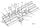
- Fig. 1 which shows a schematic and by no means true to scale representation of an embodiment of a transport path according to the invention
- two conveyor lines are arranged side by side 1.
- the conveyor line 1 arranged on the left in the transport direction or in the illustration above is the main transport direction, and the lower section 1 shown on the right in the transport direction represents a branch.
- sample holders 6, 7, 8 In the conveyor lines 1 run laterally on sidewalls arranged conveyor belt 2, which are driven and on which sample holders 6, 7, 8 sit and transported, in which sample containers 3 are held with laboratory samples. Examples of such laboratory samples may be urine samples, blood samples, but also solid samples or liquid-dissolved samples for laboratory analysis.
- the sample holders 6, 7, 8 have a substantially square base body with rounded corners. On all four lateral longitudinal sides of the sample holder iron plates are arranged centrally, which form a magnetic holding portion.
- a control body in the form of a setting wheel 4, the equi-angularly distributed along its circumference (at an angular distance of 120 °) has a total of three magnets 5.
- the thumbwheel 4 is arranged rotatable about a central axis, wherein a motor drive 9 is provided for direct driving of the wheel 4.
- a sample holder 6 is located in the region of the switch, wherein the adjusting wheel 4 has been rotated into an angular position in which one of the magnets 5 acts on a holding section of the sample holder 6 opposite thereto.
- the drive 9 now moves the setting wheel 4 synchronized with a peripheral speed corresponding to the speed of the conveyor belt 2 and thus pulls the sample holder 6 together with the sample vessel 3 arranged thereon along the direction of the arrow 10 through the opening in the lateral guide into the branch, ie In this conveyor section there is already a previously sorted sample holder 7.
- the branch conveyor belts 2 run in the new conveying direction and thus ensure the removal of the sample holder 7 and the sample holder 6, after this has been transferred to the branch.
- the magnet 5 is released from the holding section on the sample holder 6, so that the transition to the removal movement can be controlled by the circulating conveyor belt 2 in the branch .
- the rotational speed of the adjusting wheel 4 is reduced to lateral accelerations in the transfer of the sample holder 6 for removal into the branch to minimize.
- the setting wheel 4 is repositioned to transfer a subsequent further sample holder 8 in the branch (magnet 5 in the direction of the holding portion of the passing sample holder aligned) or to let the following sample holder 8 in the main transport direction continue (position of the setting wheel 4 so in that no magnet points in the direction of the holding section of the sample holder 8.
- the switch sensor unit which is located upstream of the switch in the region of the sample holder 8 and once a position detection of an approaching sample holder 8, on the other hand, an evaluation for detecting the individualizing identifier of the sample holder 8 is used.
- This unit is connected to a control, also not shown, which in turn controls the motor drive 9 of the adjusting wheel 4 to position this adjusting wheel 4 and to synchronize in its run with the drive speed of the conveyor belt 2 in the conveyor section 1 shown in the figure above so as to ensure a safe detection and transfer of a sample holder in the branch.
- the individualized recognition of the sample holder can be carried out in known manner e.g. with barcodes, through data matrix codes or via radio frequency identification (RF-ID).
- the controller may be formed in particular in the form of a microcomputer.
Claims (9)
- Ligne de transport (1) pour échantillons de laboratoire dans un laboratoire d'analyses disposant d'un embranchement et d'un aiguillage disposé dans l'embranchement permettant de commander un flux de matériaux des échantillons de laboratoire guidés dans la ligne de transport (1) sur des porte-échantillons (6, 7, 8) pourvus d'un matériau magnétique dans une section de retenue, dans laquelle un corps de réglage pouvant être mis en rotation, sous forme de roue de réglage (4) comportant au moins un aimant (5) disposé sur son périmètre, dans l'embranchement, est prévu de telle sorte que lors de la rotation de la roue de réglage (4), l'aimant (5) détecte la section de retenue du porte-échantillons (6, 7, 8) et que le porte-échantillons (6, 7, 8) est ainsi transféré dans l'embranchement, dans laquelle la roue de réglage (4) est disposée dans une section, dans laquelle une paroi de guidage latérale de la ligne de transport (1) est interrompue pour assurer le transfert du porte-échantillons (6, 7, 8) dans l'embranchement, de telle sorte que ladite roue, lors de la rotation, détecte la section de retenue disposée latéralement sur le porte-échantillons (6, 7, 8) et que le porte-échantillons (6, 7, 8) est ainsi transféré dans l'embranchement, caractérisée en ce que la roue de réglage (4) constitue un prolongement de section de guidage avec une section périphérique dans une zone dans laquelle la paroi de guidage latérale de la ligne de transport est interrompue.
- Ligne de transport selon la revendication 1, caractérisée en ce que l'aimant (5) de la roue de réglage (4) est conçu comme électroaimant.
- Ligne de transport selon l'une quelconque des revendications précédentes, caractérisée par une commande permettant l'activation ciblée de l'aiguillage et l'entraînement de la roue de réglage (4).
- Ligne de transport selon la revendication 3, caractérisée en ce qu'elle comporte un capteur relié à la commande permettant de reconnaître la position d'un porte-échantillons (6, 7, 8) pénétrant dans la zone de l'aiguillage.
- Ligne de transport selon la revendication 4, caractérisée en ce que le capteur permettant de reconnaître la position contient une cellule photoélectrique, au moins un interrupteur de proximité ou au moins un capteur de Hall.
- Ligne de transport selon l'une quelconque des revendications 4 ou 5, caractérisée en ce que la commande est conçue, pour préaligner la roue de réglage (4) pour garantir une détection optimale de la section de retenue du porte-échantillons (6, 7, 8) avec l'aimant (5), lors de la détection de la position d'un porte-échantillons (6, 7, 8) pénétrant dans la zone de l'aiguillage.
- Ligne de transport selon l'une quelconque des revendications 3 à 6, caractérisée en ce qu'elle présente un dispositif d'interprétation relié au système de commande pour interpréter une désignation placée sur le porte-échantillons (6, 7, 8) et identifiant celui-ci et que la commande est conçue pour activer l'aiguillage seulement pour les porte-échantillons (6, 7, 8) reconnus et prévus pour le transfert dans l'embranchement.
- Ligne de transport selon l'une quelconque des revendications précédentes, caractérisée en ce que la roue de réglage (4) est installée dans son système d'entraînement de telle sorte que la vitesse de rotation de la roue de réglage (4) correspond à une vitesse d'écoulement dans la ligne de transport (1) lors de la détection d'un porte-échantillons (6, 7, 8) par l'aimant (5).
- Ligne de transport selon l'une quelconque des revendications précédentes, caractérisée en ce que la roue de réglage (4) est installée dans son système d'entraînement de telle sorte que la vitesse de rotation de la roue de réglage baisse de façon uniforme lors de la rentrée par pivotement d'un porte-échantillons (6, 7, 8) dans l'embranchement, avant que la section de retenue ne soit effleurée par l'aimant (5), de telle sorte que les effets d'accélération sont minimisés au niveau du porte-échantillons (6, 7, 8).
Priority Applications (4)
| Application Number | Priority Date | Filing Date | Title |
|---|---|---|---|
| ES09177226T ES2381540T3 (es) | 2009-11-26 | 2009-11-26 | Aguja dispuesta en un ramal de una banda de transporte para muestras de laboratorio en un laboratorio analítico |
| EP09177226A EP2327646B1 (fr) | 2009-11-26 | 2009-11-26 | Aiguillage agencé dans un détournement d'une bande de transport pour échantillons de laboratoire dans un laboratoire d'analyse |
| AT09177226T ATE544703T1 (de) | 2009-11-26 | 2009-11-26 | In einem abzweig einer transportbahn für laborproben in einem analytischen labor angeordnete weiche |
| PCT/EP2010/068011 WO2011064200A1 (fr) | 2009-11-26 | 2010-11-23 | Aiguillage agencé dans un embranchement d'une voie de transport d'échantillons de laboratoire dans un laboratoire d'analyse |
Applications Claiming Priority (1)
| Application Number | Priority Date | Filing Date | Title |
|---|---|---|---|
| EP09177226A EP2327646B1 (fr) | 2009-11-26 | 2009-11-26 | Aiguillage agencé dans un détournement d'une bande de transport pour échantillons de laboratoire dans un laboratoire d'analyse |
Publications (2)
| Publication Number | Publication Date |
|---|---|
| EP2327646A1 EP2327646A1 (fr) | 2011-06-01 |
| EP2327646B1 true EP2327646B1 (fr) | 2012-02-08 |
Family
ID=42115659
Family Applications (1)
| Application Number | Title | Priority Date | Filing Date |
|---|---|---|---|
| EP09177226A Active EP2327646B1 (fr) | 2009-11-26 | 2009-11-26 | Aiguillage agencé dans un détournement d'une bande de transport pour échantillons de laboratoire dans un laboratoire d'analyse |
Country Status (4)
| Country | Link |
|---|---|
| EP (1) | EP2327646B1 (fr) |
| AT (1) | ATE544703T1 (fr) |
| ES (1) | ES2381540T3 (fr) |
| WO (1) | WO2011064200A1 (fr) |
Families Citing this family (50)
| Publication number | Priority date | Publication date | Assignee | Title |
|---|---|---|---|---|
| DE102010028769A1 (de) | 2010-05-07 | 2011-11-10 | Pvt Probenverteiltechnik Gmbh | System zum Transportieren von Behältern zwischen unterschiedlichen Stationen und Behälterträger |
| EP2589968A1 (fr) | 2011-11-04 | 2013-05-08 | Roche Diagnostics GmbH | Système de distribution d'échantillons de laboratoire, système de laboratoire et procédé de fonctionnement |
| EP2589967A1 (fr) | 2011-11-04 | 2013-05-08 | Roche Diagnostics GmbH | Système de distribution d'échantillon de laboratoire et procédé correspondant de fonctionnement |
| EP2589966A1 (fr) | 2011-11-04 | 2013-05-08 | Roche Diagnostics GmbH | Système de distribution d'échantillon de laboratoire et procédé correspondant de fonctionnement |
| DE102014202838B3 (de) | 2014-02-17 | 2014-11-06 | Roche Pvt Gmbh | Transportvorrichtung, Probenverteilungssystem und Laborautomatierungssystem |
| DE102014202843B3 (de) | 2014-02-17 | 2014-11-06 | Roche Pvt Gmbh | Transportvorrichtung, Probenverteilungssystem und Laborautomatisierungssystem |
| EP2927168A1 (fr) | 2014-03-31 | 2015-10-07 | Roche Diagniostics GmbH | Dispositif de transport, système de distribution d'échantillons et système d'automatisation de laboratoire |
| EP2927167B1 (fr) | 2014-03-31 | 2018-04-18 | F. Hoffmann-La Roche AG | Dispositif d'envoi, système de distribution d'échantillons et système d'automatisation de laboratoire |
| EP2927625A1 (fr) | 2014-03-31 | 2015-10-07 | Roche Diagniostics GmbH | Système de distribution d'échantillons et système d'automatisation de laboratoire |
| EP2927695B1 (fr) | 2014-03-31 | 2018-08-22 | Roche Diagniostics GmbH | Système de distribution d'échantillons et système d'automatisation de laboratoire |
| EP2927163B1 (fr) | 2014-03-31 | 2018-02-28 | Roche Diagnostics GmbH | Dispositif de transport vertical, système de distribution d'échantillons et système d'automatisation de laboratoire |
| EP2957914B1 (fr) | 2014-06-17 | 2018-01-03 | Roche Diagnostics GmbH | Système de distribution d'échantillons de laboratoire et système d'automatisation de laboratoire |
| EP2977766A1 (fr) | 2014-07-24 | 2016-01-27 | Roche Diagniostics GmbH | Système de distribution d'échantillons de laboratoire et système d'automatisation de laboratoire |
| EP2995580A1 (fr) | 2014-09-09 | 2016-03-16 | Roche Diagniostics GmbH | Système de distribution d'échantillons de laboratoire et système d'automatisation de laboratoire |
| EP2995960B1 (fr) | 2014-09-09 | 2020-07-15 | Roche Diagniostics GmbH | Système de distribution d'échantillons de laboratoire et procédé d'étalonnage de capteurs magnétiques |
| US9952242B2 (en) | 2014-09-12 | 2018-04-24 | Roche Diagnostics Operations, Inc. | Laboratory sample distribution system and laboratory automation system |
| EP2995958A1 (fr) | 2014-09-15 | 2016-03-16 | Roche Diagniostics GmbH | Procédé pour faire fonctionner un système de réseau de distribution d'échantillons de laboratoire, système de distribution d' échantillons de laboratoire et système d'automatisation de laboratoire |
| EP3006943B1 (fr) | 2014-10-07 | 2020-04-22 | Roche Diagniostics GmbH | Module pour système de distribution d'échantillons de laboratoire, système de distribution d'échantillons et système d'automatisation de laboratoire |
| EP3016116A1 (fr) | 2014-11-03 | 2016-05-04 | Roche Diagniostics GmbH | Dispositif de carte de circuit imprimé, bobine pour système de distribution d'échantillons de laboratoire, système de distribution d'échantillons et système d'automatisation de laboratoire |
| EP3070479B1 (fr) | 2015-03-16 | 2019-07-03 | Roche Diagniostics GmbH | Support de transport, système de distribution de marchandises de laboratoire et système d'automatisation de laboratoire |
| EP3073270B1 (fr) | 2015-03-23 | 2019-05-29 | Roche Diagniostics GmbH | Système de distribution d'échantillons de laboratoire et système d'automatisation de laboratoire |
| EP3096146A1 (fr) | 2015-05-22 | 2016-11-23 | Roche Diagniostics GmbH | Procédé de fonctionnement d'un système de distribution d'échantillons de laboratoire, système de distribution d'échantillons de laboratoire et système d'automatisation de laboratoire |
| EP3096145B1 (fr) | 2015-05-22 | 2019-09-04 | Roche Diagniostics GmbH | Procédé d'exploitation d'un système d'automatisation de laboratoire et système d'automatisation de laboratoire |
| EP3095739A1 (fr) | 2015-05-22 | 2016-11-23 | Roche Diagniostics GmbH | Procédé de fonctionnement d'un système de distribution d'échantillons de laboratoire, système de distribution d'échantillons de laboratoire et système d'automatisation de laboratoire |
| EP3112874A1 (fr) | 2015-07-02 | 2017-01-04 | Roche Diagnostics GmbH | Module de stockage, procédé d'exploitation d'un système d'automatisation de laboratoire et système d'automatisation de laboratoire |
| EP3121603A1 (fr) | 2015-07-22 | 2017-01-25 | Roche Diagnostics GmbH | Support de récipient d'échantillon, système de distribution d'échantillons de laboratoire et système d'automatisation de laboratoire |
| EP3139175B1 (fr) | 2015-09-01 | 2021-12-15 | Roche Diagnostics GmbH | Système de distribution d'une cargaison de laboratoire, système d'automatisation de laboratoire et procédé de fonctionnement d'un système de distribution de cargaison de laboratoire |
| EP3153866A1 (fr) | 2015-10-06 | 2017-04-12 | Roche Diagnostics GmbH | Procédé de détermination d'une position de transfert intercellulaire et système d'automatisation de laboratoire |
| EP3153867B1 (fr) | 2015-10-06 | 2018-11-14 | Roche Diagniostics GmbH | Système d'automatisation de laboratoire, procédé associé et système de distribution d'échantillons de laboratoire |
| EP3156352B1 (fr) | 2015-10-13 | 2019-02-27 | Roche Diagniostics GmbH | Système de distribution d'échantillons de laboratoire et système d'automatisation de laboratoire |
| EP3156353B1 (fr) | 2015-10-14 | 2019-04-03 | Roche Diagniostics GmbH | Support de rotation d'un support de récipient d'échantillon, système de distribution d'échantillons de laboratoire et système d'automatisation de laboratoire |
| EP3211429A1 (fr) | 2016-02-26 | 2017-08-30 | Roche Diagnostics GmbH | Dispositif de transport présentant une surface d'entraînement en mosaïque |
| EP3211428A1 (fr) | 2016-02-26 | 2017-08-30 | Roche Diagnostics GmbH | Unité de dispositif de transport pour un système de distribution d'échantillons de laboratoire |
| EP3211430A1 (fr) | 2016-02-26 | 2017-08-30 | Roche Diagnostics GmbH | Dispositif de transport de modules dotés d'une plaque de base |
| JP6708787B2 (ja) | 2016-06-03 | 2020-06-10 | エフ.ホフマン−ラ ロシュ アーゲーF. Hoffmann−La Roche Aktiengesellschaft | ラボラトリ試料分配システム及びラボラトリ自動化システム |
| EP3255519B1 (fr) | 2016-06-09 | 2019-02-20 | Roche Diagniostics GmbH | Système de distribution d'échantillons de laboratoire et procédé d'exploitation d'un tel système |
| EP3260867A1 (fr) | 2016-06-21 | 2017-12-27 | Roche Diagnostics GmbH | Procédé de détermination d'une position de transfert et système d'automatisation de laboratoire |
| JP6752350B2 (ja) | 2016-08-04 | 2020-09-09 | エフ.ホフマン−ラ ロシュ アーゲーF. Hoffmann−La Roche Aktiengesellschaft | ラボラトリ試料分配システム及びラボラトリ自動化システム |
| DE102016013486B3 (de) | 2016-11-11 | 2018-01-04 | Admedes Schuessler Gmbh | Flechtmaschine und Weiche für eine Flechtmaschine |
| EP3330717B1 (fr) | 2016-12-01 | 2022-04-06 | Roche Diagnostics GmbH | Système de distribution d'échantillons de laboratoire et système d'automatisation de laboratoire |
| US20180180634A1 (en) * | 2016-12-02 | 2018-06-28 | Gen-Probe Incorporated | Laboratory automated instruments, systems, and methods for transporting sample receptacle carriers |
| EP3343232B1 (fr) | 2016-12-29 | 2021-09-15 | Roche Diagnostics GmbH | Système de distribution d'échantillons de laboratoire et système d'automatisation de laboratoire |
| EP3355065B1 (fr) | 2017-01-31 | 2021-08-18 | Roche Diagnostics GmbH | Système de distribution d'échantillons de laboratoire et système d'automatisation de laboratoire |
| EP3357842B1 (fr) | 2017-02-03 | 2022-03-23 | Roche Diagnostics GmbH | Système d'automatisation de laboratoire |
| EP3410123B1 (fr) | 2017-06-02 | 2023-09-20 | Roche Diagnostics GmbH | Procédé de fonctionnement d'un système de distribution d'échantillons de laboratoire, système de distribution d'échantillons de laboratoire et système d'automatisation de laboratoire |
| EP3428653B1 (fr) | 2017-07-13 | 2021-09-15 | Roche Diagnostics GmbH | Procédé de fonctionnement d'un système de distribution d'échantillon de laboratoire, système de distribution d'échantillon de laboratoire, et système d'automation de laboratoire |
| EP3456415B1 (fr) | 2017-09-13 | 2021-10-20 | Roche Diagnostics GmbH | Support de récipient d'échantillon, système de distribution d'échantillons de laboratoire et système d'automatisation de laboratoire |
| EP3457144B1 (fr) | 2017-09-13 | 2021-10-20 | Roche Diagnostics GmbH | Support de récipient d'échantillon, système de distribution d'échantillons de laboratoire et système d'automatisation de laboratoire |
| EP3540443B1 (fr) | 2018-03-16 | 2023-08-30 | Roche Diagnostics GmbH | Système de laboratoire, système de distribution d'échantillons de laboratoire et système d'automatisation de laboratoire |
| US11747356B2 (en) | 2020-12-21 | 2023-09-05 | Roche Diagnostics Operations, Inc. | Support element for a modular transport plane, modular transport plane, and laboratory distribution system |
Family Cites Families (5)
| Publication number | Priority date | Publication date | Assignee | Title |
|---|---|---|---|---|
| DE4329078C2 (de) | 1993-08-31 | 1999-12-16 | Krups Gmbh | Vorrichtung zum Führen von Werkstückträgern in Führungsbahnen, insbesondere in Montagestraßen |
| DE4434714C2 (de) | 1994-09-28 | 1996-10-17 | Froreich Andre Von | Fördersystem |
| JP2899535B2 (ja) * | 1995-02-20 | 1999-06-02 | 照明 伊藤 | 検体容器ホルダーおよびホルダー搬送装置 |
| EP0775650A1 (fr) * | 1995-11-24 | 1997-05-28 | André Dr. von Froreich | Système de transport, notamment pour porteurs de matériaux destinés à être utilisés dans des laboratoires médicaux |
| JP3839441B2 (ja) | 2004-03-22 | 2006-11-01 | 株式会社アイディエス | 試験管搬送路の搬送方向変換装置 |
-
2009
- 2009-11-26 ES ES09177226T patent/ES2381540T3/es active Active
- 2009-11-26 EP EP09177226A patent/EP2327646B1/fr active Active
- 2009-11-26 AT AT09177226T patent/ATE544703T1/de active
-
2010
- 2010-11-23 WO PCT/EP2010/068011 patent/WO2011064200A1/fr active Application Filing
Also Published As
| Publication number | Publication date |
|---|---|
| ATE544703T1 (de) | 2012-02-15 |
| EP2327646A1 (fr) | 2011-06-01 |
| ES2381540T3 (es) | 2012-05-29 |
| WO2011064200A1 (fr) | 2011-06-03 |
Similar Documents
| Publication | Publication Date | Title |
|---|---|---|
| EP2327646B1 (fr) | Aiguillage agencé dans un détournement d'une bande de transport pour échantillons de laboratoire dans un laboratoire d'analyse | |
| EP2927163B1 (fr) | Dispositif de transport vertical, système de distribution d'échantillons et système d'automatisation de laboratoire | |
| EP0384885B1 (fr) | Distributeur pour exemplaires isolés | |
| EP2051916B1 (fr) | Dispositif de transfert, equipement de transport et procede de manutention des porte-pieces | |
| WO2013120811A1 (fr) | Système de transport pour échantillons de matières, notamment pour échantillons médicaux | |
| EP3122682B1 (fr) | Procédé et système de contrôle de récipients remplis | |
| EP2927695A1 (fr) | Système de distribution d'échantillons et système d'automatisation de laboratoire | |
| EP0601213A1 (fr) | Dispositif de transport de matières | |
| WO2013098202A1 (fr) | Système de transport et procédé pour faire fonctionner ce système | |
| DE19819812C2 (de) | Laborprimärprobenverteiler mit einer Verteileinrichtung | |
| EP1846309B1 (fr) | Dispositif et procede de tri de recipients non ranges dans un systeme de preparation de commandes | |
| AT501826A1 (de) | Vorrichtung zum fördern und vereinzeln von ferromagnetischen teilen | |
| DE4230175A1 (de) | Vorrichtung zur automatischen entladung von test- und sortieranlagen | |
| DE3244331A1 (de) | Verbessertes transport- und ueberfuehrungssystem | |
| DE3701931C2 (fr) | ||
| EP3436832B1 (fr) | Dispositif de transport | |
| DE4010116A1 (de) | Transportverfahren und -vorrichtung fuer behaelter | |
| DE602004006990T2 (de) | Gerät für ein sortiersystem und sortierverfahren | |
| DE10039897A1 (de) | Feinausrichtstation und Verfahren zum Betrieb derselben | |
| WO2020156694A1 (fr) | Robot de préhension destiné à recevoir et à déposer des bouteilles habillées et/ou des emballages habillés, installation de traitement de bouteilles et/ou d'emballages, et procédé destiné à faire fonctionner l'installation de traitement de bouteilles et/ou d'emballages | |
| DE19518328C1 (de) | Vorrichtung und Verfahren zum Sortieren von länglichen metallischen Gegenständen, insbesondere von Besteckteilen | |
| EP3348862A1 (fr) | Système tendeur de courroie | |
| EP3501677A1 (fr) | Machine de nettoyage de bouteilles destinée au nettoyage de bouteilles et procédé de nettoyage de bouteilles | |
| EP3613293B1 (fr) | Dispositif et procédé de traitement de saucisses | |
| EP3831528B1 (fr) | Porte-pièce d'une machine d'usinage pour pièces plates |
Legal Events
| Date | Code | Title | Description |
|---|---|---|---|
| PUAI | Public reference made under article 153(3) epc to a published international application that has entered the european phase |
Free format text: ORIGINAL CODE: 0009012 |
|
| AK | Designated contracting states |
Kind code of ref document: A1 Designated state(s): AT BE BG CH CY CZ DE DK EE ES FI FR GB GR HR HU IE IS IT LI LT LU LV MC MK MT NL NO PL PT RO SE SI SK SM TR |
|
| AX | Request for extension of the european patent |
Extension state: AL BA RS |
|
| GRAP | Despatch of communication of intention to grant a patent |
Free format text: ORIGINAL CODE: EPIDOSNIGR1 |
|
| 17P | Request for examination filed |
Effective date: 20110919 |
|
| RIC1 | Information provided on ipc code assigned before grant |
Ipc: G01N 35/04 20060101ALI20111007BHEP Ipc: B65G 47/84 20060101AFI20111007BHEP |
|
| GRAS | Grant fee paid |
Free format text: ORIGINAL CODE: EPIDOSNIGR3 |
|
| GRAA | (expected) grant |
Free format text: ORIGINAL CODE: 0009210 |
|
| AK | Designated contracting states |
Kind code of ref document: B1 Designated state(s): AT BE BG CH CY CZ DE DK EE ES FI FR GB GR HR HU IE IS IT LI LT LU LV MC MK MT NL NO PL PT RO SE SI SK SM TR |
|
| REG | Reference to a national code |
Ref country code: GB Ref legal event code: FG4D Free format text: NOT ENGLISH |
|
| REG | Reference to a national code |
Ref country code: CH Ref legal event code: EP Ref country code: AT Ref legal event code: REF Ref document number: 544703 Country of ref document: AT Kind code of ref document: T Effective date: 20120215 |
|
| REG | Reference to a national code |
Ref country code: DE Ref legal event code: R096 Ref document number: 502009002702 Country of ref document: DE Effective date: 20120405 |
|
| REG | Reference to a national code |
Ref country code: NL Ref legal event code: T3 |
|
| REG | Reference to a national code |
Ref country code: ES Ref legal event code: FG2A Ref document number: 2381540 Country of ref document: ES Kind code of ref document: T3 Effective date: 20120529 |
|
| LTIE | Lt: invalidation of european patent or patent extension |
Effective date: 20120208 |
|
| PG25 | Lapsed in a contracting state [announced via postgrant information from national office to epo] |
Ref country code: NO Free format text: LAPSE BECAUSE OF FAILURE TO SUBMIT A TRANSLATION OF THE DESCRIPTION OR TO PAY THE FEE WITHIN THE PRESCRIBED TIME-LIMIT Effective date: 20120508 Ref country code: HR Free format text: LAPSE BECAUSE OF FAILURE TO SUBMIT A TRANSLATION OF THE DESCRIPTION OR TO PAY THE FEE WITHIN THE PRESCRIBED TIME-LIMIT Effective date: 20120208 Ref country code: LT Free format text: LAPSE BECAUSE OF FAILURE TO SUBMIT A TRANSLATION OF THE DESCRIPTION OR TO PAY THE FEE WITHIN THE PRESCRIBED TIME-LIMIT Effective date: 20120208 Ref country code: IS Free format text: LAPSE BECAUSE OF FAILURE TO SUBMIT A TRANSLATION OF THE DESCRIPTION OR TO PAY THE FEE WITHIN THE PRESCRIBED TIME-LIMIT Effective date: 20120608 |
|
| REG | Reference to a national code |
Ref country code: IE Ref legal event code: FD4D |
|
| PG25 | Lapsed in a contracting state [announced via postgrant information from national office to epo] |
Ref country code: LV Free format text: LAPSE BECAUSE OF FAILURE TO SUBMIT A TRANSLATION OF THE DESCRIPTION OR TO PAY THE FEE WITHIN THE PRESCRIBED TIME-LIMIT Effective date: 20120208 Ref country code: FI Free format text: LAPSE BECAUSE OF FAILURE TO SUBMIT A TRANSLATION OF THE DESCRIPTION OR TO PAY THE FEE WITHIN THE PRESCRIBED TIME-LIMIT Effective date: 20120208 Ref country code: PL Free format text: LAPSE BECAUSE OF FAILURE TO SUBMIT A TRANSLATION OF THE DESCRIPTION OR TO PAY THE FEE WITHIN THE PRESCRIBED TIME-LIMIT Effective date: 20120208 Ref country code: PT Free format text: LAPSE BECAUSE OF FAILURE TO SUBMIT A TRANSLATION OF THE DESCRIPTION OR TO PAY THE FEE WITHIN THE PRESCRIBED TIME-LIMIT Effective date: 20120608 Ref country code: GR Free format text: LAPSE BECAUSE OF FAILURE TO SUBMIT A TRANSLATION OF THE DESCRIPTION OR TO PAY THE FEE WITHIN THE PRESCRIBED TIME-LIMIT Effective date: 20120509 |
|
| PG25 | Lapsed in a contracting state [announced via postgrant information from national office to epo] |
Ref country code: CY Free format text: LAPSE BECAUSE OF FAILURE TO SUBMIT A TRANSLATION OF THE DESCRIPTION OR TO PAY THE FEE WITHIN THE PRESCRIBED TIME-LIMIT Effective date: 20120208 |
|
| PG25 | Lapsed in a contracting state [announced via postgrant information from national office to epo] |
Ref country code: EE Free format text: LAPSE BECAUSE OF FAILURE TO SUBMIT A TRANSLATION OF THE DESCRIPTION OR TO PAY THE FEE WITHIN THE PRESCRIBED TIME-LIMIT Effective date: 20120208 Ref country code: IE Free format text: LAPSE BECAUSE OF FAILURE TO SUBMIT A TRANSLATION OF THE DESCRIPTION OR TO PAY THE FEE WITHIN THE PRESCRIBED TIME-LIMIT Effective date: 20120208 Ref country code: SE Free format text: LAPSE BECAUSE OF FAILURE TO SUBMIT A TRANSLATION OF THE DESCRIPTION OR TO PAY THE FEE WITHIN THE PRESCRIBED TIME-LIMIT Effective date: 20120208 Ref country code: CZ Free format text: LAPSE BECAUSE OF FAILURE TO SUBMIT A TRANSLATION OF THE DESCRIPTION OR TO PAY THE FEE WITHIN THE PRESCRIBED TIME-LIMIT Effective date: 20120208 Ref country code: RO Free format text: LAPSE BECAUSE OF FAILURE TO SUBMIT A TRANSLATION OF THE DESCRIPTION OR TO PAY THE FEE WITHIN THE PRESCRIBED TIME-LIMIT Effective date: 20120208 Ref country code: DK Free format text: LAPSE BECAUSE OF FAILURE TO SUBMIT A TRANSLATION OF THE DESCRIPTION OR TO PAY THE FEE WITHIN THE PRESCRIBED TIME-LIMIT Effective date: 20120208 Ref country code: SI Free format text: LAPSE BECAUSE OF FAILURE TO SUBMIT A TRANSLATION OF THE DESCRIPTION OR TO PAY THE FEE WITHIN THE PRESCRIBED TIME-LIMIT Effective date: 20120208 |
|
| PG25 | Lapsed in a contracting state [announced via postgrant information from national office to epo] |
Ref country code: SK Free format text: LAPSE BECAUSE OF FAILURE TO SUBMIT A TRANSLATION OF THE DESCRIPTION OR TO PAY THE FEE WITHIN THE PRESCRIBED TIME-LIMIT Effective date: 20120208 |
|
| PLBE | No opposition filed within time limit |
Free format text: ORIGINAL CODE: 0009261 |
|
| STAA | Information on the status of an ep patent application or granted ep patent |
Free format text: STATUS: NO OPPOSITION FILED WITHIN TIME LIMIT |
|
| 26N | No opposition filed |
Effective date: 20121109 |
|
| REG | Reference to a national code |
Ref country code: DE Ref legal event code: R097 Ref document number: 502009002702 Country of ref document: DE Effective date: 20121109 |
|
| BERE | Be: lapsed |
Owner name: GLP SYSTEMS G.M.B.H. Effective date: 20121130 |
|
| PG25 | Lapsed in a contracting state [announced via postgrant information from national office to epo] |
Ref country code: BG Free format text: LAPSE BECAUSE OF FAILURE TO SUBMIT A TRANSLATION OF THE DESCRIPTION OR TO PAY THE FEE WITHIN THE PRESCRIBED TIME-LIMIT Effective date: 20120508 |
|
| PG25 | Lapsed in a contracting state [announced via postgrant information from national office to epo] |
Ref country code: BE Free format text: LAPSE BECAUSE OF NON-PAYMENT OF DUE FEES Effective date: 20121130 |
|
| PG25 | Lapsed in a contracting state [announced via postgrant information from national office to epo] |
Ref country code: MT Free format text: LAPSE BECAUSE OF FAILURE TO SUBMIT A TRANSLATION OF THE DESCRIPTION OR TO PAY THE FEE WITHIN THE PRESCRIBED TIME-LIMIT Effective date: 20120208 |
|
| PG25 | Lapsed in a contracting state [announced via postgrant information from national office to epo] |
Ref country code: MC Free format text: LAPSE BECAUSE OF NON-PAYMENT OF DUE FEES Effective date: 20121130 Ref country code: TR Free format text: LAPSE BECAUSE OF FAILURE TO SUBMIT A TRANSLATION OF THE DESCRIPTION OR TO PAY THE FEE WITHIN THE PRESCRIBED TIME-LIMIT Effective date: 20120208 |
|
| PG25 | Lapsed in a contracting state [announced via postgrant information from national office to epo] |
Ref country code: SM Free format text: LAPSE BECAUSE OF FAILURE TO SUBMIT A TRANSLATION OF THE DESCRIPTION OR TO PAY THE FEE WITHIN THE PRESCRIBED TIME-LIMIT Effective date: 20120208 Ref country code: LU Free format text: LAPSE BECAUSE OF NON-PAYMENT OF DUE FEES Effective date: 20121126 |
|
| REG | Reference to a national code |
Ref country code: CH Ref legal event code: PL |
|
| PG25 | Lapsed in a contracting state [announced via postgrant information from national office to epo] |
Ref country code: HU Free format text: LAPSE BECAUSE OF FAILURE TO SUBMIT A TRANSLATION OF THE DESCRIPTION OR TO PAY THE FEE WITHIN THE PRESCRIBED TIME-LIMIT Effective date: 20091126 Ref country code: CH Free format text: LAPSE BECAUSE OF NON-PAYMENT OF DUE FEES Effective date: 20131130 Ref country code: LI Free format text: LAPSE BECAUSE OF NON-PAYMENT OF DUE FEES Effective date: 20131130 |
|
| PG25 | Lapsed in a contracting state [announced via postgrant information from national office to epo] |
Ref country code: MK Free format text: LAPSE BECAUSE OF FAILURE TO SUBMIT A TRANSLATION OF THE DESCRIPTION OR TO PAY THE FEE WITHIN THE PRESCRIBED TIME-LIMIT Effective date: 20120208 |
|
| REG | Reference to a national code |
Ref country code: FR Ref legal event code: PLFP Year of fee payment: 7 |
|
| REG | Reference to a national code |
Ref country code: AT Ref legal event code: MM01 Ref document number: 544703 Country of ref document: AT Kind code of ref document: T Effective date: 20141126 |
|
| PG25 | Lapsed in a contracting state [announced via postgrant information from national office to epo] |
Ref country code: AT Free format text: LAPSE BECAUSE OF NON-PAYMENT OF DUE FEES Effective date: 20141126 |
|
| REG | Reference to a national code |
Ref country code: FR Ref legal event code: PLFP Year of fee payment: 8 |
|
| REG | Reference to a national code |
Ref country code: FR Ref legal event code: PLFP Year of fee payment: 9 |
|
| REG | Reference to a national code |
Ref country code: DE Ref legal event code: R082 Ref document number: 502009002702 Country of ref document: DE Representative=s name: RAFFAY & FLECK PATENTANWAELTE, DE Ref country code: DE Ref legal event code: R081 Ref document number: 502009002702 Country of ref document: DE Owner name: ABBOTT AUTOMATION SOLUTIONS GMBH, DE Free format text: FORMER OWNER: GLP SYSTEMS GMBH, 21079 HAMBURG, DE |
|
| REG | Reference to a national code |
Ref country code: GB Ref legal event code: 732E Free format text: REGISTERED BETWEEN 20200213 AND 20200219 |
|
| REG | Reference to a national code |
Ref country code: DE Ref legal event code: R082 Ref document number: 502009002702 Country of ref document: DE Representative=s name: RAFFAY & FLECK PATENTANWAELTE, DE Ref country code: DE Ref legal event code: R081 Ref document number: 502009002702 Country of ref document: DE Owner name: ABBOTT AUTOMATION SOLUTIONS GMBH, DE Free format text: FORMER OWNER: ABBOTT AUTOMATION SOLUTIONS GMBH, 21079 HAMBURG, DE |
|
| REG | Reference to a national code |
Ref country code: ES Ref legal event code: PC2A Owner name: ABBOTT AUTOMATION SOLUTIONS GMBH Effective date: 20200720 |
|
| REG | Reference to a national code |
Ref country code: NL Ref legal event code: PD Owner name: ABBOTT AUTOMATION SOLUTIONS GMBH; DE Free format text: DETAILS ASSIGNMENT: CHANGE OF OWNER(S), MERGE; FORMER OWNER NAME: GLP SYSTEMS GMBH Effective date: 20200709 |
|
| P01 | Opt-out of the competence of the unified patent court (upc) registered |
Effective date: 20230623 |
|
| PGFP | Annual fee paid to national office [announced via postgrant information from national office to epo] |
Ref country code: NL Payment date: 20231012 Year of fee payment: 15 |
|
| PGFP | Annual fee paid to national office [announced via postgrant information from national office to epo] |
Ref country code: GB Payment date: 20231013 Year of fee payment: 15 |
|
| PGFP | Annual fee paid to national office [announced via postgrant information from national office to epo] |
Ref country code: ES Payment date: 20231208 Year of fee payment: 15 |
|
| PGFP | Annual fee paid to national office [announced via postgrant information from national office to epo] |
Ref country code: IT Payment date: 20231113 Year of fee payment: 15 Ref country code: FR Payment date: 20231010 Year of fee payment: 15 Ref country code: DE Payment date: 20231010 Year of fee payment: 15 |