EP2327296B1 - Verfahren zur Anpassung des Leistungsbereichs einer Butterungsmaschine an eine Rahmzuflussmenge - Google Patents
Verfahren zur Anpassung des Leistungsbereichs einer Butterungsmaschine an eine Rahmzuflussmenge Download PDFInfo
- Publication number
- EP2327296B1 EP2327296B1 EP10192440.5A EP10192440A EP2327296B1 EP 2327296 B1 EP2327296 B1 EP 2327296B1 EP 10192440 A EP10192440 A EP 10192440A EP 2327296 B1 EP2327296 B1 EP 2327296B1
- Authority
- EP
- European Patent Office
- Prior art keywords
- cream
- cylinder
- buttermaking
- dasher
- rotation
- Prior art date
- Legal status (The legal status is an assumption and is not a legal conclusion. Google has not performed a legal analysis and makes no representation as to the accuracy of the status listed.)
- Active
Links
Images


Classifications
-
- A—HUMAN NECESSITIES
- A01—AGRICULTURE; FORESTRY; ANIMAL HUSBANDRY; HUNTING; TRAPPING; FISHING
- A01J—MANUFACTURE OF DAIRY PRODUCTS
- A01J15/00—Manufacturing butter
- A01J15/10—Devices for manufacturing butter other than by churns
- A01J15/12—Devices for manufacturing butter other than by churns with arrangements for making butter in a continuous process
-
- A—HUMAN NECESSITIES
- A01—AGRICULTURE; FORESTRY; ANIMAL HUSBANDRY; HUNTING; TRAPPING; FISHING
- A01J—MANUFACTURE OF DAIRY PRODUCTS
- A01J15/00—Manufacturing butter
- A01J15/04—Rotating or oscillating churns
- A01J15/06—Rotating or oscillating churns with beating equipment which is movable in respect of the churn wall
Definitions
- the invention relates to a method according to the preamble of claim 1 and a chewing machine according to the preamble of claim 13.
- the converted cream is converted into buttercorn and buttermilk.
- This conversion of a fat in serum emulsion to a serum in fat emulsion is accomplished by destroying the membrane shell of the fat globules in the cream by shear forces of a racquet in a buttering cylinder and subsequently allowing the fat to agglomerate into buttercorn.
- the serum, so the buttermilk, is separated in the subsequent processing stages.
- a generic prior art discloses the DE 11 59 685 B , By means of an insert, two different positions of a cream intake of a churning machine can be achieved along the axis of rotation of the racket.
- the invention therefore, starting from the existing method, in the task of optimizing the operation of a buttering machine.
- the invention achieves this object by a method having the features of claim 1 and a churning machine having the features of claim 13.
- the method allows the adjustment of the power range of a churning machine to a Rahmzuhnemenge, wherein the churning machine has a buttering cylinder with a housing and a racket which is rotatably mounted about a rotation axis in the housing.
- the residence time of the buttercorn / buttermilk mixture, as well as the effectively effective club length can be adjusted.
- an adjustment of the power range to different Rahmzu mengen done.
- the cream is converted into buttercorn and buttermilk by destroying the membrane envelope of the fat globules by the shearing forces of the stick and thereby fat is liberated, which agglomerates into a lump of fat, the butter com.
- the conveying direction is the flow direction of the cream and buttercorn / buttermilk stream to a discharge channel, where the resulting buttercorn / buttermilk mixture is discharged from the buttering cylinder.
- the introduction of the cream by at least two enemas which are fixedly arranged on the housing of the buttering cylinder.
- the Rahmzumann on two or more enemas for example, depending on the Rahmzuhnemas be divided so that at low Rahmzuhnemannmenge a predominant part of the Rahmzuhnes through the front inlet, which is positioned closer to the discharge channel, and a small part of the Rahmzu bathmenge is introduced into the rear inlet.
- a majority of the Rahmzuhnes can be added via the rear inlet.
- the introduction of the cream by preferably an inlet, which is movably disposed on the housing and the Rahmzumann can take place at any position along the axis of rotation cream to the interior of the buttering cylinder.
- the setting of the power range or the effectively effective club length is carried out such that the cream can be fed by different positioning of the inlet along the axis of rotation.
- the introduction of the cream into the buttering cylinder takes place at least 30% of the total length of the racket, as with a lower total effective racket length no complete conversion of cream into buttercorn / buttermilk is ensured.
- the axis of rotation is set at an angle ⁇ to the horizontal, for specifying a conveying direction of the cream and buttercorn / buttermilk mixture.
- the hiring of the rotation axis can be done by hiring the buttering cylinder. In this case, this embodiment can also be applied to existing buttering machine.
- the axis is set at an angle of maximum 10 °.
- the angle ⁇ is preferably set once as a function of a quantitative measurement of the cream flow, so that the flow rate of the cream and buttercorn / buttermilk mixture can be adjusted by the angle ⁇ .
- the racket has at least one striking sheet which protrudes at least partially out of the horizontal alignment plane.
- An optimal conveying speed under specification of a conveying direction can be advantageously achieved by the method by the hitting sheets from a point P, which is arranged on the axis of rotation, against the conveying direction to the end of the striking sheet by an angle ⁇ of 3 - 10 ° from the horizontal Alignment plane protrudes
- the point P from which the striking sheet protrudes from the horizontal alignment plane is arranged between a first and a second inlet.
- the racket has at least one striking sheet, in which apertures are attached.
- the transition of the breakthrough between two opposite sides of the strike sheet on a slope If the racket is put into operation, it processes the cream to buttercorn and buttermilk due to shear forces and transports the mixture at the same time in a conveying direction, as act by the slope, the acting forces also to a certain extent in the conveying direction.
- a buttering cylinder of a churning machine for converting cream into buttercorn and buttermilk comprises at least one housing, a racket rotatably mounted about an axis of rotation in the cabinet, and a drainage channel, the cream inflow into the churning cylinder being accomplished either by a plurality of stationary inlets located at the Housing along the axis of rotation are arranged or by a variable inlet, which can take several positions on the housing along the axis of rotation.
- variable inlet for example, be moved along an opening opening in the housing parallel to the axis of rotation.
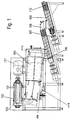
- buttering cylinder 102 with an inlet 101 for cream, and a rotatably mounted racket 103, for the formation of buttercorns and buttermilk from supplied cream. Subsequently, the buttercorn / buttermilk mixture is transferred via a channel 112 into a cooling section 104.
- the butter kernel gets a harder consistency and can then be processed better.
- a Nachbutt für strommel 105 with a drive 113 is set in the Nachbuttanssrea the optimal butter grain size. Subsequently, the buttercorn is transferred via a shaft 117 in a presser 106.
- the presser 106 converts the buttercorn into a homogeneous "water in oil emulsion" and at the same time frees the butter from buttermilk residues, which are subsequently removed.
- a mixing zone 107 water, acidic culture concentrates, aroma culture concentrates and brine are added to the butter in order to optimize the taste and consistency of the butter.
- Another Abpresser 109 together with a subsequent mixing zone 110 for a uniform distribution of water content in the butter and an optimization of the water content.
- a preferably integrated discharge pump the flow of the finished butter from the machine is guaranteed.
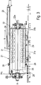
- FIG. 2 the structure of a buttering cylinder 1 is shown in detail. It shows a cylindrical housing 11, which is composed of a housing shell 11a and two housing covers 11b and 11c. These housing parts are connected to each other by flanges 9.
- a racket 2 is arranged parallel to the cylindrical housing shell 11a This racket 2 rotates about an axis of rotation A.
- the racket 2 has a shaft 2a, which runs parallel to the cylindrical housing shell 11a, and here four striking blades 3, starting from the shaft 2a extend in the direction of the cylindrical housing shell 11 a.
- the striking blades 3 are arranged in a cross shape around the impact shaft 2a and extend over a large part of the length of the buttering cylinder 1. In this case the blades 3 at regular intervals uniformly shaped openings 4, which form along the blades 3 ribs 14.
- the shaft 2a is seated at the end on bearings 6a, 6b and is coupled at one end of the shaft 2a to a drive shaft 7a of the drive 7.
- the coupling of both shafts 2a, 7a by means of a flange 10, wherein the two flange sides are toothed to each other frontally.
- the cylindrical housing shell 11 also has two pedestals 12a, 12b, which are fixedly connected to a frame 15 or frame or machine frame. Between the bases 12a, 12b and the frame 15 is a frame or machine frame 13. The Rahmzumann in the buttering cylinder 1 via the inlets 5a, 5b and 5c, which are arranged on the housing 11. The derivation of the resulting buttercream / buttermilk mixture via the discharge channel. 8
- the power range and the effective range of the churning machine can be adapted to different amounts of cream inflow.
- the entry of the cream into the interior of the buttering cylinder 1 and the arrangement of the inlets 5a-c takes place on the housing shell 11a of the churning cylinder 1 perpendicular to the axis of rotation A.
- the entry of the Rahmzu bathmenge can also be done in different quantities on all three enemas at the same time or only at two of the three enemas. Thus, over- or under-buttering can be counteracted and the buttering machine can be operated even at low Rahmzu bathmengen.
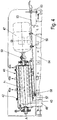
- FIG. 3 a buttering cylinder 21 is shown with a housing 31, in which a racket 22, the striking leaves 23 is arranged.
- the housing 31 consists of a substantially cylindrical housing shell 31 a and two housing covers 31 b, 31 c which are interconnected by flanges 29.
- the housing cover for example, have cylindrical sections.
- the flaps 23 close analogously FIG. 2 , to a radially rotating about the rotation axis A rotating impact wave 22a of the racket 22.
- the housing cover 31b and the housing shell 31a together form a feed channel 25, which extends parallel to the axis of rotation A and in the direction of the drive 37, not shown, is spaced from the buttering cylinder 21.
- the feed channel 25 has on the side of the chucking cylinder 21 via an opening portion B, which preferably extends over half the total length of the racket 22.
- a tubular lance 26 is guided in the supply passage 25 as inlet .
- the lance 26 is movably arranged in the feed channel 25 and allows the Rahmzumann. By moving the lance 26, the RahmzuLIN can be made at any point of the opening portion B in the interior of the buttering cylinder 21.
- the cream inflow may be supplied at a position equal to two-thirds of the total racket length.
- the flow direction of the cream in the lance 26 is parallel to the rotational axis A.
- FIG. 4 shows a variant for specifying a conveying direction X 1 of the cream in a buttering cylinder 41 in the direction of a discharge channel 48th
- the buttering cylinder 41 with a racket 42 which is rotatably mounted about an axis of rotation A and has crosswise arranged striking blades 43, substantially corresponds to the structure of the buttering cylinder 1 of FIG. 2 ,
- the racket 42 is connected via a flange 50 with the drive 47.
- three inlets 45 a - c are arranged such that the cream can be supplied, for example, in a first, second or third third of the buttering cylinder 41.
- Both the buttering cylinder 41, and the drive 47 are mounted on a plate 53 by fastening means, such as screw 58 and 59, respectively.
- the plate 53 is connected to the frame or machine frame 54 such that the plate occupies a greater distance from the frame or machine frame 54 at one end than at the opposite end.
- the aim of this device is essentially to allow a change in the axis of rotation A so that it is no longer parallel to the surface of the frame or machine frame 55, but inclined at an angle ⁇ to the parallel orientation, so that a conveying direction X 1 in the direction of the derivative channel 48 is generated.
- This angle ⁇ is formed in the present embodiment between the plate 53 and the frame or machine frame 55.
- the angle ⁇ can be chosen freely and for example be up to 10 °, particularly preferably up to 3 °.
- the plate 53 on the side with the greater distance to the frame or machine frame 55 may comprise a height-adjustable fastening means 60 with nuts 60a which connects the plate 53 to the frame or machine frame 55.
- a connector 57 Opposite this height-adjustable fastener 60 is a connector 57, which is for example designed like a hinge and which opens in the direction of the longitudinal axis of the height-adjustable fastening means 60.
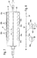
- the schematically illustrated buttering cylinder 61 includes, inter alia, a cylindrical housing 71, in which a racket 62 is arranged rotatably about an axis of rotation A.
- the racket 62 has in FIG. 6 eight crosswise arranged striking blades 63 a, b with uniformly shaped openings 64, so that the material of the striking blades 63 a, b, which is arranged between the openings 64 are formed as ribs 74.
- enemas 65 a - c cream can be supplied at different lengths of the racket 62.
- a striking sheet 63a is arranged such that it runs along the axis of rotation A over the length L 1 . In this case, every second flick is angled over a length L2, or employed.
- flaps are not limited to eight flaps, but may consist of at least 2 symmetrically arranged flaps, but also for example, 4, 6 or more flaps include, but must be arranged symmetrically. At least 2 flapping sheets are bent or turned on by the flaps.
- the striking blade 63a is inclined so that it spans a plane which rises continuously from the point P by a pitch angle ⁇ with respect to the axis of rotation A.
- the inclined club face 63a takes a distance t 1 of the axis of rotation A a.
- FIG. 6 shows the view of the racket 62 of FIG. 5 in the direction of arrow K, which is arranged in the direction of rotation R rotatable about the axis of rotation A.
- the total here eight flaps 63a and 63b are arranged alternately, so that the striking sheet 63a can take on rotation of the racket 62 by 45 °, the position of the striking sheet 63b.
- the number of flaps is at least 2, but a racket can also include, for example, 4 or 6 flaps.
- the distance t 1 by which the flaps 63 are inclined at the end of the racket 62, depending on the dimensions of the racket 62, for example, be 20 to 30 cm.
- every second beat sheet is set so that it forms an inclined plane. It is also possible to make all the striking sheets.
- the inclination can not be done by hitting the striking leaves, but for example by a continuous material thickening of the striking blade by the angle ⁇ .
- FIG. 7 shows a further embodiment in which the conveying direction X 3 is predetermined by the structure of the buttering cylinder 81.
- the buttering cylinder 81 has a racket 82 with an axis of rotation A, which has crosswise arranged striking blades 83.
- the striking leaves 83 have openings 84a, b. Between the apertures 84a, b, a respective striking sheet 83 has ribs 94a, b.
- the area of the ribs 94 b between the sides of the striking sheet 83 is chamfered.
- FIG. 8 is a section of the striking sheet 83 from FIG. 7 .
- the hatched area 94 ' is the cutout of a flap leaf rib 94a, b and the unshaded area 84' is the cutout of a cutout 84a, b.
- the enlarged detail ( Fig. 8a ) shows that the transition from the aperture 84a to the rib 94a is perpendicular to the plane of the striking blade.
- FIG. 8b shows that the transition from the opening 84b to the rib 94b is bevelled by an angle ⁇ .
- This bevel 100 may for example be between 30 to 60 °, preferably 45 °.
- the method according to the invention can be optimized in terms of control and regulation.
- the entry of the individual Rahmzu to the respective fixed enemas depending on the Rahmzuhnemenge be controlled. This is done, for example, by a measuring and control unit, e.g. by quantity measurement of the Rahmhnees or determination of the current consumption of the drive of the racket and a subsequent quantity sharing for the individual enemas in dependence on the determined Rahmzu bathmenge done. Likewise, the positioning of an inlet lance in dependence on the current Rahmzu bathmenge done.
- the method according to the invention can be combined with further methods, for example for adapting the drive power of the racket to characteristic values of the rack.
Landscapes
- Life Sciences & Earth Sciences (AREA)
- Animal Husbandry (AREA)
- Environmental Sciences (AREA)
- Dairy Products (AREA)
Applications Claiming Priority (1)
| Application Number | Priority Date | Filing Date | Title |
|---|---|---|---|
| DE200910056222 DE102009056222A1 (de) | 2009-11-28 | 2009-11-28 | Verfahren zur Anpassung des Leistungsbereichs einer Butterungsmaschine an eine Rahmzuflussmenge |
Publications (2)
| Publication Number | Publication Date |
|---|---|
| EP2327296A1 EP2327296A1 (de) | 2011-06-01 |
| EP2327296B1 true EP2327296B1 (de) | 2016-03-30 |
Family
ID=43771737
Family Applications (1)
| Application Number | Title | Priority Date | Filing Date |
|---|---|---|---|
| EP10192440.5A Active EP2327296B1 (de) | 2009-11-28 | 2010-11-24 | Verfahren zur Anpassung des Leistungsbereichs einer Butterungsmaschine an eine Rahmzuflussmenge |
Country Status (4)
| Country | Link |
|---|---|
| EP (1) | EP2327296B1 (pl) |
| DE (1) | DE102009056222A1 (pl) |
| DK (1) | DK2327296T3 (pl) |
| PL (1) | PL2327296T3 (pl) |
Families Citing this family (2)
| Publication number | Priority date | Publication date | Assignee | Title |
|---|---|---|---|---|
| DE102011117195A1 (de) * | 2011-10-29 | 2013-05-02 | Gea Mechanical Equipment Gmbh | Verfahren zur Optimierung eines automatisierten Butterungsprozesses |
| DE102016109678B4 (de) * | 2016-05-25 | 2023-11-09 | Gea Mechanical Equipment Gmbh | Vorrichtung zum Herstellen von Butter |
Family Cites Families (4)
| Publication number | Priority date | Publication date | Assignee | Title |
|---|---|---|---|---|
| GB415056A (en) * | 1933-02-15 | 1934-08-15 | Charles England Falkner | Improvements in butter churning or working apparatus |
| US3069996A (en) * | 1958-06-09 | 1962-12-25 | Roy P Robichaux | Butter churning apparatus |
| DE1159685B (de) * | 1962-02-28 | 1963-12-19 | Holstein & Kappert Maschf | Kontinuierlich arbeitende Butterungsmaschine |
| DE3529677C1 (de) * | 1984-07-17 | 1986-09-11 | Westfalia Separator Ag, 4740 Oelde | Kontinuierlich arbeitende Butterungsmaschine |
-
2009
- 2009-11-28 DE DE200910056222 patent/DE102009056222A1/de not_active Withdrawn
-
2010
- 2010-11-24 DK DK10192440.5T patent/DK2327296T3/en active
- 2010-11-24 EP EP10192440.5A patent/EP2327296B1/de active Active
- 2010-11-24 PL PL10192440.5T patent/PL2327296T3/pl unknown
Also Published As
| Publication number | Publication date |
|---|---|
| DK2327296T3 (en) | 2016-07-25 |
| DE102009056222A1 (de) | 2011-06-01 |
| PL2327296T3 (pl) | 2016-09-30 |
| EP2327296A1 (de) | 2011-06-01 |
Similar Documents
| Publication | Publication Date | Title |
|---|---|---|
| DE4433039B4 (de) | Vorrichtungen zum Bearbeiten von Dispersionen | |
| EP0565887B1 (de) | Maschine zum Bearbeiten von Schokolademassen und Verwendung zur Herstellung von Crumb | |
| EP2353707B1 (de) | Vorrichtung und Verfahren zum Mischen und Kneten von Massen, insbesondere Schokoladenmassen | |
| DE1133221B (de) | Hammermuehle | |
| DE60208700T2 (de) | Schälgerät und zugehörige verfahren | |
| EP2986365A1 (de) | Paddel, paddelschiene, mischerwelle eines mischers, mischer und ein verfahren zum mischen | |
| EP3066188B1 (de) | Rühreinrichtung für einen fermenter einer biogasanlage und verfahren zur herstellung einer rühreinrichtung | |
| DE69005433T2 (de) | Mühle zur herstellung einer suspension bestehend aus festen teilchen in einem fetten träger. | |
| WO2012080041A1 (de) | Vorrichtung zum benetzen von körnerfrüchten mit einer flüssigkeit sowie verfahren zum benetzen von körnerfrüchten mit einer flüssigkeit | |
| DE19648875A1 (de) | Vorrichtung zur Behandlung von pump- und oder rührfähigen Massen, insbesondere Fermenter vorzugsweise für Biomasse | |
| EP2327296B1 (de) | Verfahren zur Anpassung des Leistungsbereichs einer Butterungsmaschine an eine Rahmzuflussmenge | |
| WO1984004055A1 (fr) | Installation pour la preparation de materiaux coulants | |
| DE2147280A1 (de) | Schrot- und Mischanlage | |
| DE3327283A1 (de) | Arbeitsverfahren einer maschine zur entrindung von holzspaenen | |
| DE2341639B2 (de) | Verfahren und Vorrichtung zur Herstellung von Schokoladenmassen | |
| EP2595474B1 (de) | Vorrichtung zur herstellung von butter | |
| DE1924922A1 (de) | Mischmaschine | |
| DE3112994C2 (de) | Autoklav zum Aufbereiten von Kakaomasse | |
| EP0211230A2 (de) | Vorrichtung zum Mischen von Feststoffen und Flüssigkeiten | |
| DE102022126914A1 (de) | Zuführbeschleuniger für eine landwirtschaftliche erntemaschine | |
| EP2319297A1 (de) | Vorrichtung und Verfahren zum Herstellen von mehreren Buttersorten | |
| EP0664087A1 (de) | Vorrichtung zur thermischen Konditionierung von Futtermitteln und dergleichen | |
| DE1945615A1 (de) | Verfahren und Anlage zum Verfluessigen und Verruehren raffinierter Schokolade | |
| EP3871486A1 (de) | Schlegeleinheit | |
| DE1937268C3 (de) | Verfahren und Vorrichtung zur Herstellung von Schokolade |
Legal Events
| Date | Code | Title | Description |
|---|---|---|---|
| PUAI | Public reference made under article 153(3) epc to a published international application that has entered the european phase |
Free format text: ORIGINAL CODE: 0009012 |
|
| AK | Designated contracting states |
Kind code of ref document: A1 Designated state(s): AL AT BE BG CH CY CZ DE DK EE ES FI FR GB GR HR HU IE IS IT LI LT LU LV MC MK MT NL NO PL PT RO RS SE SI SK SM TR |
|
| AX | Request for extension of the european patent |
Extension state: BA ME |
|
| 17P | Request for examination filed |
Effective date: 20111004 |
|
| 17Q | First examination report despatched |
Effective date: 20141222 |
|
| GRAP | Despatch of communication of intention to grant a patent |
Free format text: ORIGINAL CODE: EPIDOSNIGR1 |
|
| RIC1 | Information provided on ipc code assigned before grant |
Ipc: A01J 15/06 20060101ALI20151026BHEP Ipc: A01J 15/12 20060101AFI20151026BHEP |
|
| INTG | Intention to grant announced |
Effective date: 20151110 |
|
| GRAS | Grant fee paid |
Free format text: ORIGINAL CODE: EPIDOSNIGR3 |
|
| GRAA | (expected) grant |
Free format text: ORIGINAL CODE: 0009210 |
|
| AK | Designated contracting states |
Kind code of ref document: B1 Designated state(s): AL AT BE BG CH CY CZ DE DK EE ES FI FR GB GR HR HU IE IS IT LI LT LU LV MC MK MT NL NO PL PT RO RS SE SI SK SM TR |
|
| REG | Reference to a national code |
Ref country code: GB Ref legal event code: FG4D Free format text: NOT ENGLISH |
|
| REG | Reference to a national code |
Ref country code: CH Ref legal event code: EP |
|
| REG | Reference to a national code |
Ref country code: AT Ref legal event code: REF Ref document number: 784280 Country of ref document: AT Kind code of ref document: T Effective date: 20160415 |
|
| REG | Reference to a national code |
Ref country code: IE Ref legal event code: FG4D Free format text: LANGUAGE OF EP DOCUMENT: GERMAN |
|
| REG | Reference to a national code |
Ref country code: DE Ref legal event code: R096 Ref document number: 502010011317 Country of ref document: DE |
|
| REG | Reference to a national code |
Ref country code: CH Ref legal event code: NV Representative=s name: ISLER AND PEDRAZZINI AG, CH |
|
| REG | Reference to a national code |
Ref country code: NL Ref legal event code: FP |
|
| REG | Reference to a national code |
Ref country code: LT Ref legal event code: MG4D Ref country code: DK Ref legal event code: T3 Effective date: 20160714 |
|
| PG25 | Lapsed in a contracting state [announced via postgrant information from national office to epo] |
Ref country code: FI Free format text: LAPSE BECAUSE OF FAILURE TO SUBMIT A TRANSLATION OF THE DESCRIPTION OR TO PAY THE FEE WITHIN THE PRESCRIBED TIME-LIMIT Effective date: 20160330 Ref country code: NO Free format text: LAPSE BECAUSE OF FAILURE TO SUBMIT A TRANSLATION OF THE DESCRIPTION OR TO PAY THE FEE WITHIN THE PRESCRIBED TIME-LIMIT Effective date: 20160630 Ref country code: HR Free format text: LAPSE BECAUSE OF FAILURE TO SUBMIT A TRANSLATION OF THE DESCRIPTION OR TO PAY THE FEE WITHIN THE PRESCRIBED TIME-LIMIT Effective date: 20160330 Ref country code: GR Free format text: LAPSE BECAUSE OF FAILURE TO SUBMIT A TRANSLATION OF THE DESCRIPTION OR TO PAY THE FEE WITHIN THE PRESCRIBED TIME-LIMIT Effective date: 20160701 |
|
| PG25 | Lapsed in a contracting state [announced via postgrant information from national office to epo] |
Ref country code: LT Free format text: LAPSE BECAUSE OF FAILURE TO SUBMIT A TRANSLATION OF THE DESCRIPTION OR TO PAY THE FEE WITHIN THE PRESCRIBED TIME-LIMIT Effective date: 20160330 Ref country code: RS Free format text: LAPSE BECAUSE OF FAILURE TO SUBMIT A TRANSLATION OF THE DESCRIPTION OR TO PAY THE FEE WITHIN THE PRESCRIBED TIME-LIMIT Effective date: 20160330 Ref country code: LV Free format text: LAPSE BECAUSE OF FAILURE TO SUBMIT A TRANSLATION OF THE DESCRIPTION OR TO PAY THE FEE WITHIN THE PRESCRIBED TIME-LIMIT Effective date: 20160330 Ref country code: SE Free format text: LAPSE BECAUSE OF FAILURE TO SUBMIT A TRANSLATION OF THE DESCRIPTION OR TO PAY THE FEE WITHIN THE PRESCRIBED TIME-LIMIT Effective date: 20160330 |
|
| PG25 | Lapsed in a contracting state [announced via postgrant information from national office to epo] |
Ref country code: IS Free format text: LAPSE BECAUSE OF FAILURE TO SUBMIT A TRANSLATION OF THE DESCRIPTION OR TO PAY THE FEE WITHIN THE PRESCRIBED TIME-LIMIT Effective date: 20160730 Ref country code: EE Free format text: LAPSE BECAUSE OF FAILURE TO SUBMIT A TRANSLATION OF THE DESCRIPTION OR TO PAY THE FEE WITHIN THE PRESCRIBED TIME-LIMIT Effective date: 20160330 |
|
| REG | Reference to a national code |
Ref country code: FR Ref legal event code: PLFP Year of fee payment: 7 |
|
| PG25 | Lapsed in a contracting state [announced via postgrant information from national office to epo] |
Ref country code: SM Free format text: LAPSE BECAUSE OF FAILURE TO SUBMIT A TRANSLATION OF THE DESCRIPTION OR TO PAY THE FEE WITHIN THE PRESCRIBED TIME-LIMIT Effective date: 20160330 Ref country code: PT Free format text: LAPSE BECAUSE OF FAILURE TO SUBMIT A TRANSLATION OF THE DESCRIPTION OR TO PAY THE FEE WITHIN THE PRESCRIBED TIME-LIMIT Effective date: 20160801 Ref country code: SK Free format text: LAPSE BECAUSE OF FAILURE TO SUBMIT A TRANSLATION OF THE DESCRIPTION OR TO PAY THE FEE WITHIN THE PRESCRIBED TIME-LIMIT Effective date: 20160330 Ref country code: RO Free format text: LAPSE BECAUSE OF FAILURE TO SUBMIT A TRANSLATION OF THE DESCRIPTION OR TO PAY THE FEE WITHIN THE PRESCRIBED TIME-LIMIT Effective date: 20160330 Ref country code: ES Free format text: LAPSE BECAUSE OF FAILURE TO SUBMIT A TRANSLATION OF THE DESCRIPTION OR TO PAY THE FEE WITHIN THE PRESCRIBED TIME-LIMIT Effective date: 20160330 Ref country code: CZ Free format text: LAPSE BECAUSE OF FAILURE TO SUBMIT A TRANSLATION OF THE DESCRIPTION OR TO PAY THE FEE WITHIN THE PRESCRIBED TIME-LIMIT Effective date: 20160330 |
|
| REG | Reference to a national code |
Ref country code: DE Ref legal event code: R097 Ref document number: 502010011317 Country of ref document: DE |
|
| PLBE | No opposition filed within time limit |
Free format text: ORIGINAL CODE: 0009261 |
|
| STAA | Information on the status of an ep patent application or granted ep patent |
Free format text: STATUS: NO OPPOSITION FILED WITHIN TIME LIMIT |
|
| PG25 | Lapsed in a contracting state [announced via postgrant information from national office to epo] |
Ref country code: BE Free format text: LAPSE BECAUSE OF NON-PAYMENT OF DUE FEES Effective date: 20161130 |
|
| 26N | No opposition filed |
Effective date: 20170103 |
|
| PG25 | Lapsed in a contracting state [announced via postgrant information from national office to epo] |
Ref country code: SI Free format text: LAPSE BECAUSE OF FAILURE TO SUBMIT A TRANSLATION OF THE DESCRIPTION OR TO PAY THE FEE WITHIN THE PRESCRIBED TIME-LIMIT Effective date: 20160330 |
|
| PG25 | Lapsed in a contracting state [announced via postgrant information from national office to epo] |
Ref country code: LU Free format text: LAPSE BECAUSE OF NON-PAYMENT OF DUE FEES Effective date: 20161130 |
|
| REG | Reference to a national code |
Ref country code: FR Ref legal event code: PLFP Year of fee payment: 8 |
|
| REG | Reference to a national code |
Ref country code: AT Ref legal event code: MM01 Ref document number: 784280 Country of ref document: AT Kind code of ref document: T Effective date: 20161124 |
|
| PG25 | Lapsed in a contracting state [announced via postgrant information from national office to epo] |
Ref country code: AT Free format text: LAPSE BECAUSE OF NON-PAYMENT OF DUE FEES Effective date: 20161124 |
|
| REG | Reference to a national code |
Ref country code: BE Ref legal event code: MM Effective date: 20161130 |
|
| PG25 | Lapsed in a contracting state [announced via postgrant information from national office to epo] |
Ref country code: CY Free format text: LAPSE BECAUSE OF FAILURE TO SUBMIT A TRANSLATION OF THE DESCRIPTION OR TO PAY THE FEE WITHIN THE PRESCRIBED TIME-LIMIT Effective date: 20160330 Ref country code: HU Free format text: LAPSE BECAUSE OF FAILURE TO SUBMIT A TRANSLATION OF THE DESCRIPTION OR TO PAY THE FEE WITHIN THE PRESCRIBED TIME-LIMIT; INVALID AB INITIO Effective date: 20101124 |
|
| PG25 | Lapsed in a contracting state [announced via postgrant information from national office to epo] |
Ref country code: MK Free format text: LAPSE BECAUSE OF FAILURE TO SUBMIT A TRANSLATION OF THE DESCRIPTION OR TO PAY THE FEE WITHIN THE PRESCRIBED TIME-LIMIT Effective date: 20160330 Ref country code: TR Free format text: LAPSE BECAUSE OF FAILURE TO SUBMIT A TRANSLATION OF THE DESCRIPTION OR TO PAY THE FEE WITHIN THE PRESCRIBED TIME-LIMIT Effective date: 20160330 Ref country code: MC Free format text: LAPSE BECAUSE OF FAILURE TO SUBMIT A TRANSLATION OF THE DESCRIPTION OR TO PAY THE FEE WITHIN THE PRESCRIBED TIME-LIMIT Effective date: 20160330 |
|
| PG25 | Lapsed in a contracting state [announced via postgrant information from national office to epo] |
Ref country code: BG Free format text: LAPSE BECAUSE OF FAILURE TO SUBMIT A TRANSLATION OF THE DESCRIPTION OR TO PAY THE FEE WITHIN THE PRESCRIBED TIME-LIMIT Effective date: 20160330 |
|
| PG25 | Lapsed in a contracting state [announced via postgrant information from national office to epo] |
Ref country code: MT Free format text: LAPSE BECAUSE OF FAILURE TO SUBMIT A TRANSLATION OF THE DESCRIPTION OR TO PAY THE FEE WITHIN THE PRESCRIBED TIME-LIMIT Effective date: 20160330 |
|
| PG25 | Lapsed in a contracting state [announced via postgrant information from national office to epo] |
Ref country code: AL Free format text: LAPSE BECAUSE OF FAILURE TO SUBMIT A TRANSLATION OF THE DESCRIPTION OR TO PAY THE FEE WITHIN THE PRESCRIBED TIME-LIMIT Effective date: 20160330 |
|
| P01 | Opt-out of the competence of the unified patent court (upc) registered |
Effective date: 20230402 |
|
| PGFP | Annual fee paid to national office [announced via postgrant information from national office to epo] |
Ref country code: NL Payment date: 20231127 Year of fee payment: 14 |
|
| PGFP | Annual fee paid to national office [announced via postgrant information from national office to epo] |
Ref country code: GB Payment date: 20231123 Year of fee payment: 14 |
|
| PGFP | Annual fee paid to national office [announced via postgrant information from national office to epo] |
Ref country code: IT Payment date: 20231129 Year of fee payment: 14 Ref country code: IE Payment date: 20231122 Year of fee payment: 14 Ref country code: DK Payment date: 20231122 Year of fee payment: 14 |
|
| PGFP | Annual fee paid to national office [announced via postgrant information from national office to epo] |
Ref country code: PL Payment date: 20231023 Year of fee payment: 14 |
|
| REG | Reference to a national code |
Ref country code: DK Ref legal event code: EBP Effective date: 20241130 |
|
| REG | Reference to a national code |
Ref country code: NL Ref legal event code: MM Effective date: 20241201 |
|
| GBPC | Gb: european patent ceased through non-payment of renewal fee |
Effective date: 20241124 |
|
| PG25 | Lapsed in a contracting state [announced via postgrant information from national office to epo] |
Ref country code: NL Free format text: LAPSE BECAUSE OF NON-PAYMENT OF DUE FEES Effective date: 20241201 |
|
| PG25 | Lapsed in a contracting state [announced via postgrant information from national office to epo] |
Ref country code: DK Free format text: LAPSE BECAUSE OF NON-PAYMENT OF DUE FEES Effective date: 20241130 |
|
| PG25 | Lapsed in a contracting state [announced via postgrant information from national office to epo] |
Ref country code: IT Free format text: LAPSE BECAUSE OF NON-PAYMENT OF DUE FEES Effective date: 20241124 |
|
| PG25 | Lapsed in a contracting state [announced via postgrant information from national office to epo] |
Ref country code: GB Free format text: LAPSE BECAUSE OF NON-PAYMENT OF DUE FEES Effective date: 20241124 |
|
| PG25 | Lapsed in a contracting state [announced via postgrant information from national office to epo] |
Ref country code: IE Free format text: LAPSE BECAUSE OF NON-PAYMENT OF DUE FEES Effective date: 20241124 |
|
| REG | Reference to a national code |
Ref country code: CH Ref legal event code: U11 Free format text: ST27 STATUS EVENT CODE: U-0-0-U10-U11 (AS PROVIDED BY THE NATIONAL OFFICE) Effective date: 20251201 |
|
| PGFP | Annual fee paid to national office [announced via postgrant information from national office to epo] |
Ref country code: DE Payment date: 20251201 Year of fee payment: 16 |
|
| PGFP | Annual fee paid to national office [announced via postgrant information from national office to epo] |
Ref country code: FR Payment date: 20251128 Year of fee payment: 16 |
|
| PGFP | Annual fee paid to national office [announced via postgrant information from national office to epo] |
Ref country code: CH Payment date: 20251201 Year of fee payment: 16 |