EP2325922A1 - Bloc-batterie - Google Patents
Bloc-batterie Download PDFInfo
- Publication number
- EP2325922A1 EP2325922A1 EP10174073A EP10174073A EP2325922A1 EP 2325922 A1 EP2325922 A1 EP 2325922A1 EP 10174073 A EP10174073 A EP 10174073A EP 10174073 A EP10174073 A EP 10174073A EP 2325922 A1 EP2325922 A1 EP 2325922A1
- Authority
- EP
- European Patent Office
- Prior art keywords
- battery module
- battery
- plate
- battery pack
- top plate
- Prior art date
- Legal status (The legal status is an assumption and is not a legal conclusion. Google has not performed a legal analysis and makes no representation as to the accuracy of the status listed.)
- Granted
Links
- 238000007789 sealing Methods 0.000 claims description 38
- 239000007789 gas Substances 0.000 description 45
- 239000002341 toxic gas Substances 0.000 description 6
- WHXSMMKQMYFTQS-UHFFFAOYSA-N Lithium Chemical compound [Li] WHXSMMKQMYFTQS-UHFFFAOYSA-N 0.000 description 4
- 238000004880 explosion Methods 0.000 description 4
- 229910052744 lithium Inorganic materials 0.000 description 4
- MWUXSHHQAYIFBG-UHFFFAOYSA-N Nitric oxide Chemical compound O=[N] MWUXSHHQAYIFBG-UHFFFAOYSA-N 0.000 description 3
- 230000008602 contraction Effects 0.000 description 3
- 238000002485 combustion reaction Methods 0.000 description 2
- 230000008878 coupling Effects 0.000 description 2
- 238000010168 coupling process Methods 0.000 description 2
- 238000005859 coupling reaction Methods 0.000 description 2
- 238000007872 degassing Methods 0.000 description 2
- 238000010586 diagram Methods 0.000 description 2
- 239000004215 Carbon black (E152) Substances 0.000 description 1
- UGFAIRIUMAVXCW-UHFFFAOYSA-N Carbon monoxide Chemical compound [O+]#[C-] UGFAIRIUMAVXCW-UHFFFAOYSA-N 0.000 description 1
- 229910003307 Ni-Cd Inorganic materials 0.000 description 1
- 230000003466 anti-cipated effect Effects 0.000 description 1
- 229910002091 carbon monoxide Inorganic materials 0.000 description 1
- 238000006243 chemical reaction Methods 0.000 description 1
- 230000003247 decreasing effect Effects 0.000 description 1
- 238000007599 discharging Methods 0.000 description 1
- 238000005516 engineering process Methods 0.000 description 1
- 230000002708 enhancing effect Effects 0.000 description 1
- 238000003912 environmental pollution Methods 0.000 description 1
- 239000002803 fossil fuel Substances 0.000 description 1
- 229930195733 hydrocarbon Natural products 0.000 description 1
- 150000002430 hydrocarbons Chemical class 0.000 description 1
- 238000000034 method Methods 0.000 description 1
- 239000000126 substance Substances 0.000 description 1
- 238000004804 winding Methods 0.000 description 1
Images


Classifications
-
- H—ELECTRICITY
- H01—ELECTRIC ELEMENTS
- H01M—PROCESSES OR MEANS, e.g. BATTERIES, FOR THE DIRECT CONVERSION OF CHEMICAL ENERGY INTO ELECTRICAL ENERGY
- H01M50/00—Constructional details or processes of manufacture of the non-active parts of electrochemical cells other than fuel cells, e.g. hybrid cells
- H01M50/30—Arrangements for facilitating escape of gases
-
- H—ELECTRICITY
- H01—ELECTRIC ELEMENTS
- H01M—PROCESSES OR MEANS, e.g. BATTERIES, FOR THE DIRECT CONVERSION OF CHEMICAL ENERGY INTO ELECTRICAL ENERGY
- H01M50/00—Constructional details or processes of manufacture of the non-active parts of electrochemical cells other than fuel cells, e.g. hybrid cells
- H01M50/10—Primary casings, jackets or wrappings of a single cell or a single battery
- H01M50/183—Sealing members
-
- H—ELECTRICITY
- H01—ELECTRIC ELEMENTS
- H01M—PROCESSES OR MEANS, e.g. BATTERIES, FOR THE DIRECT CONVERSION OF CHEMICAL ENERGY INTO ELECTRICAL ENERGY
- H01M50/00—Constructional details or processes of manufacture of the non-active parts of electrochemical cells other than fuel cells, e.g. hybrid cells
- H01M50/20—Mountings; Secondary casings or frames; Racks, modules or packs; Suspension devices; Shock absorbers; Transport or carrying devices; Holders
- H01M50/204—Racks, modules or packs for multiple batteries or multiple cells
- H01M50/207—Racks, modules or packs for multiple batteries or multiple cells characterised by their shape
- H01M50/209—Racks, modules or packs for multiple batteries or multiple cells characterised by their shape adapted for prismatic or rectangular cells
-
- H—ELECTRICITY
- H01—ELECTRIC ELEMENTS
- H01M—PROCESSES OR MEANS, e.g. BATTERIES, FOR THE DIRECT CONVERSION OF CHEMICAL ENERGY INTO ELECTRICAL ENERGY
- H01M50/00—Constructional details or processes of manufacture of the non-active parts of electrochemical cells other than fuel cells, e.g. hybrid cells
- H01M50/20—Mountings; Secondary casings or frames; Racks, modules or packs; Suspension devices; Shock absorbers; Transport or carrying devices; Holders
- H01M50/258—Modular batteries; Casings provided with means for assembling
-
- Y—GENERAL TAGGING OF NEW TECHNOLOGICAL DEVELOPMENTS; GENERAL TAGGING OF CROSS-SECTIONAL TECHNOLOGIES SPANNING OVER SEVERAL SECTIONS OF THE IPC; TECHNICAL SUBJECTS COVERED BY FORMER USPC CROSS-REFERENCE ART COLLECTIONS [XRACs] AND DIGESTS
- Y02—TECHNOLOGIES OR APPLICATIONS FOR MITIGATION OR ADAPTATION AGAINST CLIMATE CHANGE
- Y02E—REDUCTION OF GREENHOUSE GAS [GHG] EMISSIONS, RELATED TO ENERGY GENERATION, TRANSMISSION OR DISTRIBUTION
- Y02E60/00—Enabling technologies; Technologies with a potential or indirect contribution to GHG emissions mitigation
- Y02E60/10—Energy storage using batteries
-
- Y—GENERAL TAGGING OF NEW TECHNOLOGICAL DEVELOPMENTS; GENERAL TAGGING OF CROSS-SECTIONAL TECHNOLOGIES SPANNING OVER SEVERAL SECTIONS OF THE IPC; TECHNICAL SUBJECTS COVERED BY FORMER USPC CROSS-REFERENCE ART COLLECTIONS [XRACs] AND DIGESTS
- Y02—TECHNOLOGIES OR APPLICATIONS FOR MITIGATION OR ADAPTATION AGAINST CLIMATE CHANGE
- Y02P—CLIMATE CHANGE MITIGATION TECHNOLOGIES IN THE PRODUCTION OR PROCESSING OF GOODS
- Y02P70/00—Climate change mitigation technologies in the production process for final industrial or consumer products
- Y02P70/50—Manufacturing or production processes characterised by the final manufactured product
-
- Y—GENERAL TAGGING OF NEW TECHNOLOGICAL DEVELOPMENTS; GENERAL TAGGING OF CROSS-SECTIONAL TECHNOLOGIES SPANNING OVER SEVERAL SECTIONS OF THE IPC; TECHNICAL SUBJECTS COVERED BY FORMER USPC CROSS-REFERENCE ART COLLECTIONS [XRACs] AND DIGESTS
- Y10—TECHNICAL SUBJECTS COVERED BY FORMER USPC
- Y10T—TECHNICAL SUBJECTS COVERED BY FORMER US CLASSIFICATION
- Y10T29/00—Metal working
- Y10T29/49—Method of mechanical manufacture
- Y10T29/49826—Assembling or joining
Definitions
- One or more embodiments of the present invention relate to a battery pack, and more particularly, to a structure of a battery pack.
- Vehicle exhaust emission includes large amounts of harmful substances, such as nitrogen oxide due to combustion, carbon monoxide or hydrocarbon due to imperfect combustion, or the like, and is recognized as a serious environmental pollution problem.
- fossil fuels are anticipated to be exhausted in the not too distant future, development of next generation energy sources and hybrid electric vehicles have become important issues.
- mileage of such vehicles is determined by battery performance. In general, batteries do not have enough electrical energy for powering hybrid electric vehicles for a satisfactory period of time or mileage. If vehicles use energy sources such as gasoline, light oil, gas, or the like, the vehicles may quickly refuel in filling stations or gas charging stations. However, even when an electric charging station is available, it takes a long time to charge a hybrid electric vehicle, which is an obstacle to commercialization.
- improving battery performance compared to other technologies regarding hybrid electric vehicles, is recognized as an important problem.
- One or more embodiments of the present invention include a battery pack comprising a plurality of stacked battery modules each including secondary batteries, which prevents deviation of the secondary batteries by effectively supporting its weight and effectively emits gas, generated in the battery modules, to the outside. Additional aspects will be set forth in part in the description which follows and, in part, will be apparent from the description, or may be learned by practice of the presented embodiments.
- a battery pack comprising at least a first battery module and a second battery module, wherein the second battery module is arranged below the first battery module along a first direction.
- Each battery module comprises a plurality of secondary batteries stacked along a second direction, wherein at least one of the secondary batteries comprises a gas vent.
- Each battery module further comprises a top plate disposed on the top surface of the plurality of secondary batteries, and a bottom plate formed below the bottom surface of the plurality of secondary batteries, wherein the bottom plate of the first battery module and the top plate of the second battery module are contacting each other. Further, at least one opening is provided in the top plate corresponding to locations of the gas vent of the at least one secondary battery.
- a sealing member is preferably interposed between the bottom plate of the first battery module and the top plate of the second battery module for sealing therebetween.
- each secondary battery comprises a gas vent and openings are provided in the top plates corresponding to locations of the vents of the secondary batteries.
- a sealing ring is preferably interposed between each of the openings of the top plate and the respective vents.
- the bottom plate of the first battery module and the top plate of the second battery module are preferably configured to form a gas discharge path while contacting each other.
- gas vented from the gas vents of the secondary batteries can be guided along the duct to the exterior.
- the top plate may comprise a first plate and a second plate extending upwardly from a longitudinal side of the first plate
- the bottom plate may comprise a third plate and a fourth plate extending downwardly from a longitudinal side of the third plate.
- the battery pack may further comprise a pair of end plates disposed at both end portions of the secondary batteries along the second direction and the upper portions of the end plates of the second battery module may comprise a groove and at least one neighboring extending portion, wherein the groove is formed to receive the top plate of the second battery module and the bottom plate of the first battery module.
- the height of the extended portion is preferably less than a height of the bottom plate side portions plus the thickness of the base plate of the top plate.
- the first and second battery modules may be connected to each other by connecting a lower end portion of the end plate of the first battery module with an upper end portion of the end plate of the second battery module such that the bottom plate of the first battery module is press fitted to the top plate of the second battery module.
- the end plates of the first and second battery modules are preferably connected to each other by first and second connecting members.
- a further gas discharge path may be separately formed on the top plate of the uppermost battery module of the stacked battery modules.
- the battery pack may further comprise gas ducts connected to each of the gas discharge paths.
- the battery pack comprises an outer sealing body for sealing the battery pack, the sealing body comprising an opening connected to a gas duct.
- Each gas discharge path of the battery pack is preferably connected to an exhaust being located at an exterior of a passenger area of the vehicle.
- a battery pack in another embodiment, includes a plurality of stacked battery modules, wherein each of the battery modules includes a plurality of secondary batteries arranged in a predetermined direction and electrically connected to one another; a pair of end plates disposed at both end portions of the secondary batteries; a restraint plate which compresses so that the secondary batteries do not extend in a longitudinal direction and is connected to side portions of the pair of end plates; a top plate connected to upper portions of the pair of end plates and forming an opening corresponding to a vent of the secondary batteries; and a bottom plate which is connected to lower portions of the pair of end plates to support the weight of the secondary batteries and is formed to correspond to a top plate of another of the battery modules disposed underneath such that the bottom plate serves as a duct for emitting gas when gas is generated in the vent of a secondary batteries of the other battery module disposed underneath.
- An outlet may be connected to the bottom plate serving as a duct for emitting gas and the top plate of the other battery module disposed underneath to emit gas to the outside.
- the battery pack may be used in an electric vehicle.
- the battery pack may be sealed so that gas generated in the battery pack does not flow into the passenger area of the car and is emitted to the outside.
- the battery pack may include a plurality of battery modules.
- Each of the battery modules may be formed by arranging a plurality of secondary batteries in a predetermined direction and electrically connecting the secondary batteries to each other.
- Each of the secondary batteries may be a lithium secondary battery.
- each battery module may include twelve secondary batteries, and the battery pack may include eight battery modules stacked in four layers.
- the numbers of secondary batteries and battery modules are not limited thereto, and one of ordinary skill in the art would understand that various other configurations are possible.
- a longitudinal center portion of the battery module in which the secondary batteries are arranged may deviate due to its own weight.
- lithium secondary batteries have a long lifespan and light weight compared to general Ni-Cd, Ni-Mh batteries, or the like, but have a risk of explosion. When lithium secondary batteries explode due to overcharging, overdischarging, or another reason, a large amount of toxic gas is emitted.
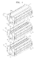
- FIGS. 1 through 4 a battery pack enhancing hardness and including a first battery module 1, a second battery module 100 and a third battery module 200 each including a duct in a bottom plate 30 thereof, wherein the duct allows a large amount of toxic gas, generated when a secondary battery 10 explodes, to be easily emitted, is illustrated.
- FIG. 1 is a schematic perspective view of the second battery module 100, the first battery module 1 and the third battery module 200 disposed one above the other, according to an embodiment of the present invention.
- FIG. 2 is an exploded perspective view of the first battery module 1 according to an embodiment of the present invention.
- FIG. 1 is a schematic perspective view of the second battery module 100, the first battery module 1 and the third battery module 200
- FIG. 3 is a front view illustrating a state in which the second battery module 100, the first battery module 1 and the third battery module 200 are coupled to each other, according to an embodiment of the present invention.
- FIG. 4 is a schematic perspective view for describing gas emission from the second battery module 100, the first battery module 1 and the third battery module 200, according to an embodiment of the present invention.
- the first and third battery modules 100 and 200 are respectively disposed below and above the first battery module 1.
- the components of the second battery module 100, the first battery module 1 and the third battery module 200 may be substantially the same and have been described above.
- the battery pack includes the second battery module 100, the first battery module 1 and the third battery module 200 stacked on top of each other.
- the first battery module 1 includes a plurality of secondary batteries 10, a top plate 20, a bottom plate 30, a restraint plate 40, and an end plate 50.
- Each of the secondary batteries 10 includes an electrode assembly (not shown), a sealing body 11, and an electrode terminal 12.
- the electrode assembly includes an anode plate (not shown), a separator (not shown), and a cathode plate (not shown), and may be a winding type or a stack type assembly.
- the sealing body 11 accommodates the electrode assembly.
- the electrode terminal 12 may protrude from the sealing body 11 and electrically connect the secondary battery 10 with an external device.
- the sealing body 11 may include a vent 13.
- the vent 13 is formed to be easily perforated so that the gas generated in the sealing body 11 can perforate the vent 13 and be emitted to the outside through the perforated vent 13.
- the plurality of secondary batteries 10 facing one another may be arranged in a predetermined direction and are electrically connected to one another.
- the secondary batteries 10 may be connected to one another in series or in parallel.
- anode plates and cathode plates of the secondary batteries 10 may be alternately arranged.
- the electrode terminals 12 of the secondary batteries 10 may be connected to each other by a bus bar 14
- the electrode assembly of the secondary battery 10 containing lithium expands or contracts through charging or discharging.
- the expansion and contraction of the electrode assembly exerts a physical force on the sealing body 11, and thus the sealing body 11 expands and contracts physically according to changes of the electrode assembly.
- the changes of the sealing body 11 may be fixed by the repeated expansion and contraction, and the expansion increases resistance thereby decreasing efficiency of the secondary battery 10.
- the one pair of end plates 50 may be arranged in a predetermined direction to be respectively disposed at both end portions of the secondary batteries 10 electrically connected to one another.
- the restraint plate 40 is connected to a side portion of the end plate 50 to compress and fix the secondary batteries 10 so that there is no variation in a lengthwise direction of the secondary batteries 10 through expansion and contraction.
- the top plate 20 is disposed on the plurality of secondary batteries 10 and connected to an upper portion of the end plate 50. Openings 20a formed in the top plate 20 are respectively disposed to correspond to the locations of the vents 13 of the secondary batteries 10.
- the size of the openings 20a may be slightly greater than the size of the vents 13. That is in a vertical projection, the circumference of a vent 13 would be fully enclosed by the circumference of an opening 20a.
- the cross section of the opening 20a may be greater than the cross section of the vent 13.
- the location of their center points match in a horizontal projection.
- the cross sections of the openings 20a and vents 13 are equal and their positions are matching such that the circumference of the openings 20a lies on top of the circumference of the vents 13 in a horizontal projection.
- the top plate 20 may include top plate side portions 20b formed on both longitudinal sides of the top plate 20 such that the top plate side portions 20b protrude upwards and the top plate 20 has a U shape.
- a first sealing member 21 formed of rubber is disposed in each of the top plate side portions 20b.
- Each of the openings 20a formed in the top plate 20 may include a sealing element, preferably a sealing ring O, between the top plate 20 and the corresponding vent 13, so that when gas is emitted from the vent 13, the gas does not affect the adjacent secondary battery 10 and is emitted through the opening 20a.
- the sealing ring O may be an O-shaped ring.
- a groove 50a is formed in an upper center portion of the end plate 50 to accommodate the top plate 20.
- the openings 20a of the top plate 20 may be disposed in close proximity to the secondary batteries 10.
- a height h 3 between a bottom surface of the end plate 50 and a bottom surface of the groove 50a formed in the upper center portion of the ending plate 50 may be formed to be equal to or less than a height h 4 of the secondary batteries 10, so that the top plate 20 may be coupled to the end plate 50 without forming a space between the secondary batteries 10 and the top plate 20 with the sealing rings O interposed therebetween.
- the top plate 20 exerts pressure on the secondary batteries 10 and compresses the sealing rings O interposed between the secondary batteries 10 and the top plate 20, and thus the top plate 20 and the secondary batteries 10 may be sealed.
- the bottom plate 30 is disposed under the secondary batteries 10 to support the weight of the plurality of secondary batteries 10, and is connected to a lower portion of the end plate 50.
- the bottom plate 30 may include bottom plate side portions 30a.
- the bottom plate side portions 30a may be formed on both longitudinal sides of the bottom plate 30 such that the bottom plate side portions 30a protrude downwards.
- the bottom plate side portions 30a form a path with the top plate 120 of the second battery module 100 underneath to serve as a duct for emitting gas when gas is generated.
- the bottom plate 30 of the first battery module 1 and the second top plate 120 of the second battery module 100, which is disposed under the bottom plate 30, may form a path for emitting gas when sealed, even if not perfectly sealed.
- the shape of the bottom plate 30 when the battery modules 1 are stacked will be described with reference to FIG. 3 .
- the battery pack may be formed by stacking the second battery module 100, the first battery module 1 and the third battery module 200 on top of one another.
- the number of stackable battery modules is not limited. However, for convenience of description, three battery modules, the second battery module 100, the first battery module 1 and the third battery module 200 are stacked in a triple-layered structure as illustrated in FIG. 3 .
- the bottom plate 30 of the first battery module 1 has a shape corresponding to that of the second top plate 120 of the second battery module 100.
- gas is generated due to explosion in a secondary battery 110 of the second battery module 100, gas is emitted through the vents 113 of the second battery module 100, and the gas is emitted through a second opening part 120a of the second top plate 120.
- the bottom plate 30 and the second top plate 120 of the second battery module 100 correspond to each other to serve as a duct which is a path of gas emission.
- a second sealing member 121 may be interposed between the bottom plate 30 of the first battery module 1 and the second top plate 120 of the second battery module 100.
- the first, second and third sealing members 21, 121, and 221 may be formed of rubber and sealed by a tightening force between the bottom plate 30 and the second top plate 120.
- the bottom plate 30 and the second top plate 120 may be joined together by coupling the end plate 50 of the first battery module 1 with the second battery module 100 disposed under the first battery module 1.
- the end plates 50 and 150 may be connected to each other by lower connecting members 51 a and 51 b.
- the second end plate 150 may have a shape in which a height h 1 of an extended portion 150b formed in an upper end portion of the second end plate 150 is less than a height h 2 of the bottom plate side portions 30a. That is, when the height h 2 of the bottom plate side portions 30a is greater than the height h 1 of the extended portion 150b formed in the upper end portion of the second end plate 150, coherence between the lower connecting members 51 a and 51 b is concentrated on between the bottom plate 30 and the second top plate 120 to seal them.
- thicknesses of the second top plate 120 and the second sealing member 121 may be considered for coherence between the bottom plate 30 and the second top plate 120.
- the second top plate 120, the second sealing member 121, and the bottom plate 30 are sequentially stacked, and the extended portion 150b formed in the upper end portion of the second end plate 150 and a lower portion of the end plate 50 are coupled by the lower connecting members 51 a and 51 b, and therefore, the thicknesses of the second top plate 120 and the second sealing member 121 affect coherence between the bottom plate 30 and the second top plate 120.
- the top plate 20 of the first battery module 1 corresponds to a third bottom plate 230 of the third battery module 200 disposed on the first battery module 1 to form a duct for emitting gas generated in the first battery module 1.
- the third battery module 200 is disposed uppermost among the first, second and third battery modules 1, 100, and 200.
- the third top plate 220 of the third battery module 200 may be covered with a duct for emitting gas.
- the duct covering the third top plate 220 may have various structures.
- the third top plate 220 may be covered with a cover C to form an integrated pipe shape in a lengthwise direction.
- the height of the third top plate 220 covered with the cover C is not greater than that of an extended portion 250b formed in an upper end portion of the third battery module 200, and thus may be formed compact in size.
- the first, second and third top plates 20, 120, and 220 of the first, second and third battery modules 1, 100, and 200, which are sequentially stacked, and the first, second and third bottom plates 30, 130, and 230 are overlapped with one another, thereby forming ducts through which gas is emitted. That is, gas emitted from the vents 13, 113, and 213 of the secondary batteries 10 may be emitted to the outside though the ducts formed by overlapping the first, second and third top plates 20, 120, and 220 and the first, second and third bottom plates 30, 130, and 230.
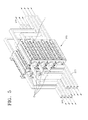
- FIG. 5 is a schematic perspective view of a battery pack 300 according to an embodiment of the present invention.
- the battery pack 300 is formed by layering four battery modules 1 in two rows, that is, the battery pack 300 includes eight battery modules 1.
- Each battery module 1 includes twelve secondary batteries 10 arranged in a predetermined direction.
- the bottom plate 30 and the top plate 20 (correspond to each other to form four degassing ducts D for emitting gas.
- Upper portions of the top plates 20 of the uppermost battery modules 1 may be covered, thereby also forming the degassing ducts D.
- Each duct D may be connected to an outlet 320 to emit gas to the outside.
- the method of emitting gas generated in the battery pack 300 to the outside is not limited thereto.
- FIG. 6 is a schematic perspective view of a battery pack 300 according to another embodiment of the present invention.
- the gas generated in the battery pack 300 may be emitted through an outlet 320 connected to the battery pack sealing body 310.
- Gas may be emitted to the outside by not only forming ducts D in the battery pack 300, but by sealing the battery pack 300 with the battery pack sealing body 310.
- FIG. 7 is a schematic conceptual diagram of a electric vehicle 400 including the battery pack 300 of FIG. 6 , according to an embodiment of the present invention.
- the battery pack 300 including the secondary batteries 10 explodes or when gas is generated due to another reason, toxic gas is explosively generated in a short time. If the toxic gas flows into a space occupied by people, it may be harmful to the people. Accordingly, as illustrated in FIG. 5 , the ducts D are formed in the battery pack 300 to emit the toxic gas to the outside of the electric vehicle 400.
- the battery pack 300 may be sealed with the battery pack sealing body 310 to emit the toxic gas through the outlet 320 to the outside of the electric vehicle 400.
- FIG. 8 is a schematic perspective view of a battery module 400 according to another embodiment of the present invention.
- a battery module 400 may include secondary batteries 10, a top plate 420, and a bottom plate 430.
- a plurality of secondary batteries may be stacked along a second direction.
- a top plate 420 may be disposed on the top surface of the plurality of secondary batteries 10. The end portions of the top plate 420a may be extended in a first direction Z to cover at least part of the side of the secondary batteries 10. The end portions of the top plate 420a may hold the secondary batteries 10.
- a bottom plate 430 may be formed below the bottom surface of the plurality of secondary batteries 10. The end portion of the bottom plate 430b may be extended to cover at least part of the side of the secondary batteries 10. Referring FIG. 8 , the bottom plate 430 and the top plate 420 may connected to each other so as to accommodate the secondary batteries 10 therein.
- the ways of coupling between the top plate 420 and the bottom plate 430 are not limited thereto.
- intervening elements may be disposed between the end portion of the top plate 420b and the end portion of the bottom plate 430b.
- the top plate 420 of the battery module 400 may contact to the bottom plate of the battery module which is arranged on the top of the battery module 400.
- the bottom plate 430 of the battery module 400 may contact to the top plate of the battery module which is arranged below the battery module 400.
Priority Applications (1)
| Application Number | Priority Date | Filing Date | Title |
|---|---|---|---|
| KR1020100088463A KR101174900B1 (ko) | 2009-11-19 | 2010-09-09 | 배터리 팩, 상기 배터리 팩 제조방법 및 이동수단 |
Applications Claiming Priority (1)
| Application Number | Priority Date | Filing Date | Title |
|---|---|---|---|
| US27293009P | 2009-11-19 | 2009-11-19 |
Publications (2)
| Publication Number | Publication Date |
|---|---|
| EP2325922A1 true EP2325922A1 (fr) | 2011-05-25 |
| EP2325922B1 EP2325922B1 (fr) | 2012-05-09 |
Family
ID=43006331
Family Applications (1)
| Application Number | Title | Priority Date | Filing Date |
|---|---|---|---|
| EP10174073A Active EP2325922B1 (fr) | 2009-11-19 | 2010-08-26 | Bloc-batterie |
Country Status (6)
| Country | Link |
|---|---|
| US (1) | US9318731B2 (fr) |
| EP (1) | EP2325922B1 (fr) |
| JP (1) | JP5362688B2 (fr) |
| KR (1) | KR101174900B1 (fr) |
| CN (1) | CN102088104B (fr) |
| AT (1) | ATE557432T1 (fr) |
Cited By (5)
| Publication number | Priority date | Publication date | Assignee | Title |
|---|---|---|---|---|
| US8623535B2 (en) | 2011-02-15 | 2014-01-07 | Samsung Sdi Co., Ltd. | Battery module |
| DE102014200203A1 (de) | 2014-01-09 | 2015-07-09 | Robert Bosch Gmbh | Elektrochemischer Energiespeicher |
| EP3799150A4 (fr) * | 2018-12-27 | 2021-10-06 | Contemporary Amperex Technology Co., Limited | Boîtier de batterie |
| EP3796412A4 (fr) * | 2018-12-29 | 2021-11-24 | Contemporary Amperex Technology Co., Limited | Bloc-batterie |
| EP3890057A4 (fr) * | 2018-12-29 | 2022-01-26 | Contemporary Amperex Technology Co., Limited | Bloc-batterie |
Families Citing this family (44)
| Publication number | Priority date | Publication date | Assignee | Title |
|---|---|---|---|---|
| DE102010041709B4 (de) * | 2010-09-30 | 2023-05-11 | Robert Bosch Gmbh | Verfahren zum Verspannen eines Lithium-Ionen-Akkumulators, ein Lithium-Ionen-Akkumulator sowie ein Kraftfahrzeug mit einem Lithium-Ionen-Akkumulator |
| JP5209019B2 (ja) | 2010-10-13 | 2013-06-12 | 日立ビークルエナジー株式会社 | 蓄電モジュールおよび蓄電装置 |
| KR101188933B1 (ko) * | 2010-10-13 | 2012-10-08 | 에스비리모티브 주식회사 | 배터리 모듈 |
| WO2012066875A1 (fr) * | 2010-11-17 | 2012-05-24 | 本田技研工業株式会社 | Unité accumulatrice pour véhicule |
| US9444118B2 (en) * | 2011-05-26 | 2016-09-13 | Samsung Sdi Co., Ltd. | Battery pack |
| DE102011076981B4 (de) * | 2011-06-06 | 2021-08-26 | Robert Bosch Gmbh | Batteriesystem, Kraftfahrzeug mit diesem Batteriesystem und Verfahren zur Herstellung einer Betriebsbereitschaft bei einem Kraftfahrzeug mit diesem Batteriesystem |
| KR101294188B1 (ko) * | 2011-11-30 | 2013-08-08 | 기아자동차주식회사 | 차량용 고전압배터리의 안전구조 |
| DE102011089142A1 (de) | 2011-12-20 | 2013-06-20 | Robert Bosch Gmbh | Stapelbares Batteriemodul |
| US9466819B2 (en) * | 2012-03-07 | 2016-10-11 | Samsung Sdi Co., Ltd. | Battery module |
| US20130260611A1 (en) * | 2012-04-03 | 2013-10-03 | Jang-Gun Ahn | Battery module |
| KR200463597Y1 (ko) | 2012-06-25 | 2012-11-16 | 이승혁 | 건전지 하우징 조립체 |
| KR20140015846A (ko) | 2012-07-25 | 2014-02-07 | 삼성에스디아이 주식회사 | 배터리 팩 |
| DE102012015816B4 (de) * | 2012-08-10 | 2023-10-26 | Dr. Ing. H.C. F. Porsche Ag | Kraftfahrzeugbatterie |
| KR101678531B1 (ko) * | 2013-01-31 | 2016-11-22 | 삼성에스디아이 주식회사 | 클린칭 결합이 적용된 배터리 모듈 |
| WO2014125807A1 (fr) * | 2013-02-14 | 2014-08-21 | 三洋電機株式会社 | Module de batterie |
| KR101678532B1 (ko) | 2013-02-21 | 2016-11-22 | 삼성에스디아이 주식회사 | 배터리 모듈 |
| JP6205807B2 (ja) * | 2013-04-08 | 2017-10-04 | 株式会社Gsユアサ | バッテリモジュール |
| WO2015019559A1 (fr) * | 2013-08-08 | 2015-02-12 | パナソニックIpマネジメント株式会社 | Unité batterie |
| KR101673972B1 (ko) | 2014-02-17 | 2016-11-08 | 주식회사 엘지화학 | 배터리 팩 |
| JP6330379B2 (ja) * | 2014-03-07 | 2018-05-30 | 株式会社豊田自動織機 | 電池パック |
| CN204144348U (zh) | 2014-03-31 | 2015-02-04 | 比亚迪股份有限公司 | 模块化电池模组壳体和具有其的电池模组 |
| JP6206308B2 (ja) | 2014-04-11 | 2017-10-04 | 株式会社豊田自動織機 | 電池パック |
| CN203871400U (zh) * | 2014-04-30 | 2014-10-08 | 比亚迪股份有限公司 | 动力电池装置 |
| US9685645B2 (en) * | 2014-07-16 | 2017-06-20 | Ford Global Technologies, Llc | Battery pack venting system for electrified vehicle |
| JP6330634B2 (ja) | 2014-11-26 | 2018-05-30 | 株式会社オートネットワーク技術研究所 | 蓄電モジュール |
| US20160197323A1 (en) * | 2015-01-05 | 2016-07-07 | Johnson Controls Technology Company | Battery module vent and handle configuration system and method |
| KR101657394B1 (ko) | 2015-02-03 | 2016-09-13 | 삼성에스디아이 주식회사 | 배터리 모듈 |
| KR102288543B1 (ko) * | 2015-03-10 | 2021-08-11 | 삼성에스디아이 주식회사 | 배터리 팩 |
| KR102314041B1 (ko) * | 2015-03-12 | 2021-10-18 | 삼성에스디아이 주식회사 | 베터리 팩 |
| JP6686286B2 (ja) * | 2015-03-30 | 2020-04-22 | 三洋電機株式会社 | 角形二次電池及びそれを用いた組電池 |
| KR102019884B1 (ko) * | 2015-11-13 | 2019-09-09 | 주식회사 엘지화학 | 배터리 모듈 및 이러한 배터리 모듈을 포함하는 배터리 팩 및 이러한 배터리 팩을 포함하는 자동차 |
| KR102092268B1 (ko) * | 2015-11-30 | 2020-03-23 | 주식회사 엘지화학 | 클램핑 부재 및 이를 이용한 배터리 모듈 |
| US10573863B2 (en) * | 2016-02-24 | 2020-02-25 | Phillips & Temro Industries Inc. | Battery and auxiliary power unit mounting system |
| JP6597440B2 (ja) * | 2016-03-25 | 2019-10-30 | トヨタ自動車株式会社 | 電池パック |
| KR20180006150A (ko) * | 2016-07-08 | 2018-01-17 | 주식회사 엘지화학 | 안전성이 개선된 셀 모듈 어셈블리 및 이를 위한 팩 구조물 |
| JP6805729B2 (ja) * | 2016-10-28 | 2020-12-23 | 株式会社デンソー | 電池組立体 |
| KR102110543B1 (ko) * | 2017-03-22 | 2020-05-13 | 주식회사 엘지화학 | 배터리 팩 |
| CN107833993B (zh) * | 2017-10-13 | 2023-06-27 | 常州普莱德新能源电池科技有限公司 | 一种节省电池箱体高度空间的双层模组 |
| KR102425695B1 (ko) | 2019-01-31 | 2022-07-28 | 삼성에스디아이 주식회사 | 전지 팩 |
| CN111668409B (zh) * | 2019-03-08 | 2021-12-07 | 比亚迪股份有限公司 | 电池托盘、动力电池包及车辆 |
| CN112331997B (zh) * | 2019-10-15 | 2021-11-12 | 宁德时代新能源科技股份有限公司 | 电池包和车辆 |
| EP4050630A4 (fr) | 2019-10-23 | 2023-01-04 | GS Yuasa International Ltd. | Dispositif de stockage électrique |
| DE102020115132A1 (de) | 2020-06-08 | 2021-12-09 | Bayerische Motoren Werke Aktiengesellschaft | Baugruppe für eine Traktionsbatterie mit Schutzeinheit, Traktionsbatterie sowie Kraftfahrzeug |
| WO2023128576A1 (fr) * | 2021-12-27 | 2023-07-06 | 주식회사 엘지에너지솔루션 | Bloc-batterie, et système de stockage d'énergie (ess) et véhicule le comprenant |
Citations (2)
| Publication number | Priority date | Publication date | Assignee | Title |
|---|---|---|---|---|
| JP2005285516A (ja) * | 2004-03-29 | 2005-10-13 | Toyoda Gosei Co Ltd | 連結部材およびバッテリーパック |
| EP1775784A1 (fr) * | 2004-08-05 | 2007-04-18 | Toyota Jidosha Kabushiki Kaisha | Module de batterie, batterie d'alimentation et procede de fabrication de module de batterie |
Family Cites Families (12)
| Publication number | Priority date | Publication date | Assignee | Title |
|---|---|---|---|---|
| JP5088688B2 (ja) * | 2005-09-30 | 2012-12-05 | Tdkラムダ株式会社 | 電池パック |
| JP4783137B2 (ja) * | 2005-12-15 | 2011-09-28 | 日立ビークルエナジー株式会社 | 電池モジュール |
| CN101411004B (zh) * | 2006-02-17 | 2012-03-21 | 尼拉国际股份公司 | 包括压力传感器的双极电池 |
| KR100892047B1 (ko) * | 2006-09-18 | 2009-04-07 | 주식회사 엘지화학 | 전지모듈 및 중대형 전지팩 |
| KR100892046B1 (ko) | 2006-09-18 | 2009-04-07 | 주식회사 엘지화학 | 전지모듈 및 그것을 포함하고 있는 중대형 전지팩 |
| FR2921718B1 (fr) * | 2007-10-01 | 2014-11-28 | Snecma | Echangeur thermique de prechauffage pour pile a combustible |
| JP5181327B2 (ja) * | 2007-10-25 | 2013-04-10 | 本田技研工業株式会社 | 蓄電装置 |
| JP5183171B2 (ja) * | 2007-11-28 | 2013-04-17 | 三洋電機株式会社 | バッテリシステム |
| JP5334420B2 (ja) * | 2008-01-16 | 2013-11-06 | 三洋電機株式会社 | バッテリシステム |
| US20090258286A1 (en) * | 2008-04-10 | 2009-10-15 | Gateway Inc. | Modular battery pack and computer and familly of computers having a modular battery pack |
| JP5372449B2 (ja) * | 2008-09-24 | 2013-12-18 | 三洋電機株式会社 | バッテリシステム |
| US8734978B2 (en) * | 2009-11-05 | 2014-05-27 | Samsung Sdi Co., Ltd. | Battery pack |
-
2010
- 2010-08-26 EP EP10174073A patent/EP2325922B1/fr active Active
- 2010-08-26 AT AT10174073T patent/ATE557432T1/de active
- 2010-09-09 KR KR1020100088463A patent/KR101174900B1/ko active IP Right Grant
- 2010-11-02 US US12/926,209 patent/US9318731B2/en active Active
- 2010-11-18 CN CN201010562726.6A patent/CN102088104B/zh active Active
- 2010-11-19 JP JP2010259000A patent/JP5362688B2/ja active Active
Patent Citations (2)
| Publication number | Priority date | Publication date | Assignee | Title |
|---|---|---|---|---|
| JP2005285516A (ja) * | 2004-03-29 | 2005-10-13 | Toyoda Gosei Co Ltd | 連結部材およびバッテリーパック |
| EP1775784A1 (fr) * | 2004-08-05 | 2007-04-18 | Toyota Jidosha Kabushiki Kaisha | Module de batterie, batterie d'alimentation et procede de fabrication de module de batterie |
Cited By (10)
| Publication number | Priority date | Publication date | Assignee | Title |
|---|---|---|---|---|
| US8623535B2 (en) | 2011-02-15 | 2014-01-07 | Samsung Sdi Co., Ltd. | Battery module |
| EP2490277B1 (fr) * | 2011-02-15 | 2018-08-22 | Samsung SDI Co., Ltd. | Module de batterie |
| DE102014200203A1 (de) | 2014-01-09 | 2015-07-09 | Robert Bosch Gmbh | Elektrochemischer Energiespeicher |
| EP3799150A4 (fr) * | 2018-12-27 | 2021-10-06 | Contemporary Amperex Technology Co., Limited | Boîtier de batterie |
| US11949114B2 (en) | 2018-12-27 | 2024-04-02 | Contemporary Amperex Technology Co., Limited | Battery box |
| EP3796412A4 (fr) * | 2018-12-29 | 2021-11-24 | Contemporary Amperex Technology Co., Limited | Bloc-batterie |
| EP3890057A4 (fr) * | 2018-12-29 | 2022-01-26 | Contemporary Amperex Technology Co., Limited | Bloc-batterie |
| US11302972B2 (en) | 2018-12-29 | 2022-04-12 | Contemporary Amperex Technology Co., Limited | Battery pack including batteries |
| US11600886B2 (en) | 2018-12-29 | 2023-03-07 | Contemporary Amperex Technology Co., Limited | Battery pack |
| EP4235925A3 (fr) * | 2018-12-29 | 2024-02-21 | Contemporary Amperex Technology Co., Limited | Bloc-batterie |
Also Published As
| Publication number | Publication date |
|---|---|
| CN102088104A (zh) | 2011-06-08 |
| JP5362688B2 (ja) | 2013-12-11 |
| ATE557432T1 (de) | 2012-05-15 |
| KR101174900B1 (ko) | 2012-08-17 |
| US20110117401A1 (en) | 2011-05-19 |
| CN102088104B (zh) | 2015-11-25 |
| US9318731B2 (en) | 2016-04-19 |
| EP2325922B1 (fr) | 2012-05-09 |
| KR20110055371A (ko) | 2011-05-25 |
| JP2011108653A (ja) | 2011-06-02 |
Similar Documents
| Publication | Publication Date | Title |
|---|---|---|
| EP2325922B1 (fr) | Bloc-batterie | |
| EP2341569B1 (fr) | Bloc-batteries | |
| US10283744B2 (en) | Battery module and battery pack | |
| US8758923B2 (en) | Battery pack | |
| CN104350633B (zh) | 具有单一电极端子连接部的电池组件 | |
| CN102117930B (zh) | 电池组 | |
| CN104488127B (zh) | 具有组装联接结构的电池模块 | |
| CN100570927C (zh) | 电池模块 | |
| EP2325923A1 (fr) | Bloc-batterie à stabilité améliorée | |
| US8197960B2 (en) | Battery module | |
| EP1928044A1 (fr) | Bouchon de connexion pour batterie rechargeable | |
| KR20120074425A (ko) | 전지모듈 및 이를 포함하는 전지팩 | |
| JP2015088312A (ja) | 電源装置 | |
| US7794872B2 (en) | Secondary battery | |
| US9620750B2 (en) | High-voltage storage device | |
| CN116249652A (zh) | 连接部件、电池单体、电池及用电设备 | |
| EP4311016A1 (fr) | Batterie secondaire ayant une structure de borne améliorée | |
| KR20130086483A (ko) | 각형 리튬형 전지롤 구조체 | |
| KR20230094180A (ko) | 배터리 모듈 및 이를 포함하는 배터리 팩 및 자동차 | |
| KR100578814B1 (ko) | 이차 전지와 이에 사용되는 캡 조립체 | |
| KR100578815B1 (ko) | 이차 전지와 이에 사용되는 캡 조립체 | |
| KR20170079249A (ko) | 전지모듈의 제조방법 및 이를 이용한 전지팩 |
Legal Events
| Date | Code | Title | Description |
|---|---|---|---|
| PUAI | Public reference made under article 153(3) epc to a published international application that has entered the european phase |
Free format text: ORIGINAL CODE: 0009012 |
|
| 17P | Request for examination filed |
Effective date: 20100826 |
|
| AK | Designated contracting states |
Kind code of ref document: A1 Designated state(s): AL AT BE BG CH CY CZ DE DK EE ES FI FR GB GR HR HU IE IS IT LI LT LU LV MC MK MT NL NO PL PT RO SE SI SK SM TR |
|
| AX | Request for extension of the european patent |
Extension state: BA ME RS |
|
| RIC1 | Information provided on ipc code assigned before grant |
Ipc: H01M 2/10 20060101AFI20110616BHEP Ipc: H01M 2/02 20060101ALI20110616BHEP Ipc: H01M 2/12 20060101ALI20110616BHEP |
|
| GRAP | Despatch of communication of intention to grant a patent |
Free format text: ORIGINAL CODE: EPIDOSNIGR1 |
|
| RIN1 | Information on inventor provided before grant (corrected) |
Inventor name: KIM, TAE-YONG Inventor name: LEE, HYUN-YE Inventor name: PARK, SHI-DONG Inventor name: KIM, MYUNG-CHUL |
|
| GRAS | Grant fee paid |
Free format text: ORIGINAL CODE: EPIDOSNIGR3 |
|
| GRAA | (expected) grant |
Free format text: ORIGINAL CODE: 0009210 |
|
| AK | Designated contracting states |
Kind code of ref document: B1 Designated state(s): AL AT BE BG CH CY CZ DE DK EE ES FI FR GB GR HR HU IE IS IT LI LT LU LV MC MK MT NL NO PL PT RO SE SI SK SM TR |
|
| REG | Reference to a national code |
Ref country code: GB Ref legal event code: FG4D |
|
| REG | Reference to a national code |
Ref country code: AT Ref legal event code: REF Ref document number: 557432 Country of ref document: AT Kind code of ref document: T Effective date: 20120515 Ref country code: CH Ref legal event code: EP |
|
| REG | Reference to a national code |
Ref country code: IE Ref legal event code: FG4D |
|
| REG | Reference to a national code |
Ref country code: DE Ref legal event code: R096 Ref document number: 602010001430 Country of ref document: DE Effective date: 20120705 |
|
| REG | Reference to a national code |
Ref country code: NL Ref legal event code: VDEP Effective date: 20120509 |
|
| REG | Reference to a national code |
Ref country code: LT Ref legal event code: MG4D Effective date: 20120509 |
|
| PG25 | Lapsed in a contracting state [announced via postgrant information from national office to epo] |
Ref country code: NO Free format text: LAPSE BECAUSE OF FAILURE TO SUBMIT A TRANSLATION OF THE DESCRIPTION OR TO PAY THE FEE WITHIN THE PRESCRIBED TIME-LIMIT Effective date: 20120809 Ref country code: PL Free format text: LAPSE BECAUSE OF FAILURE TO SUBMIT A TRANSLATION OF THE DESCRIPTION OR TO PAY THE FEE WITHIN THE PRESCRIBED TIME-LIMIT Effective date: 20120509 Ref country code: SE Free format text: LAPSE BECAUSE OF FAILURE TO SUBMIT A TRANSLATION OF THE DESCRIPTION OR TO PAY THE FEE WITHIN THE PRESCRIBED TIME-LIMIT Effective date: 20120509 Ref country code: LT Free format text: LAPSE BECAUSE OF FAILURE TO SUBMIT A TRANSLATION OF THE DESCRIPTION OR TO PAY THE FEE WITHIN THE PRESCRIBED TIME-LIMIT Effective date: 20120509 Ref country code: CY Free format text: LAPSE BECAUSE OF FAILURE TO SUBMIT A TRANSLATION OF THE DESCRIPTION OR TO PAY THE FEE WITHIN THE PRESCRIBED TIME-LIMIT Effective date: 20120509 Ref country code: FI Free format text: LAPSE BECAUSE OF FAILURE TO SUBMIT A TRANSLATION OF THE DESCRIPTION OR TO PAY THE FEE WITHIN THE PRESCRIBED TIME-LIMIT Effective date: 20120509 Ref country code: IS Free format text: LAPSE BECAUSE OF FAILURE TO SUBMIT A TRANSLATION OF THE DESCRIPTION OR TO PAY THE FEE WITHIN THE PRESCRIBED TIME-LIMIT Effective date: 20120909 |
|
| REG | Reference to a national code |
Ref country code: AT Ref legal event code: MK05 Ref document number: 557432 Country of ref document: AT Kind code of ref document: T Effective date: 20120509 |
|
| PG25 | Lapsed in a contracting state [announced via postgrant information from national office to epo] |
Ref country code: HR Free format text: LAPSE BECAUSE OF FAILURE TO SUBMIT A TRANSLATION OF THE DESCRIPTION OR TO PAY THE FEE WITHIN THE PRESCRIBED TIME-LIMIT Effective date: 20120509 Ref country code: PT Free format text: LAPSE BECAUSE OF FAILURE TO SUBMIT A TRANSLATION OF THE DESCRIPTION OR TO PAY THE FEE WITHIN THE PRESCRIBED TIME-LIMIT Effective date: 20120910 Ref country code: GR Free format text: LAPSE BECAUSE OF FAILURE TO SUBMIT A TRANSLATION OF THE DESCRIPTION OR TO PAY THE FEE WITHIN THE PRESCRIBED TIME-LIMIT Effective date: 20120810 Ref country code: SI Free format text: LAPSE BECAUSE OF FAILURE TO SUBMIT A TRANSLATION OF THE DESCRIPTION OR TO PAY THE FEE WITHIN THE PRESCRIBED TIME-LIMIT Effective date: 20120509 Ref country code: LV Free format text: LAPSE BECAUSE OF FAILURE TO SUBMIT A TRANSLATION OF THE DESCRIPTION OR TO PAY THE FEE WITHIN THE PRESCRIBED TIME-LIMIT Effective date: 20120509 |
|
| PG25 | Lapsed in a contracting state [announced via postgrant information from national office to epo] |
Ref country code: BE Free format text: LAPSE BECAUSE OF FAILURE TO SUBMIT A TRANSLATION OF THE DESCRIPTION OR TO PAY THE FEE WITHIN THE PRESCRIBED TIME-LIMIT Effective date: 20120509 |
|
| PG25 | Lapsed in a contracting state [announced via postgrant information from national office to epo] |
Ref country code: NL Free format text: LAPSE BECAUSE OF FAILURE TO SUBMIT A TRANSLATION OF THE DESCRIPTION OR TO PAY THE FEE WITHIN THE PRESCRIBED TIME-LIMIT Effective date: 20120509 Ref country code: DK Free format text: LAPSE BECAUSE OF FAILURE TO SUBMIT A TRANSLATION OF THE DESCRIPTION OR TO PAY THE FEE WITHIN THE PRESCRIBED TIME-LIMIT Effective date: 20120509 Ref country code: SK Free format text: LAPSE BECAUSE OF FAILURE TO SUBMIT A TRANSLATION OF THE DESCRIPTION OR TO PAY THE FEE WITHIN THE PRESCRIBED TIME-LIMIT Effective date: 20120509 Ref country code: AT Free format text: LAPSE BECAUSE OF FAILURE TO SUBMIT A TRANSLATION OF THE DESCRIPTION OR TO PAY THE FEE WITHIN THE PRESCRIBED TIME-LIMIT Effective date: 20120509 Ref country code: EE Free format text: LAPSE BECAUSE OF FAILURE TO SUBMIT A TRANSLATION OF THE DESCRIPTION OR TO PAY THE FEE WITHIN THE PRESCRIBED TIME-LIMIT Effective date: 20120509 Ref country code: CZ Free format text: LAPSE BECAUSE OF FAILURE TO SUBMIT A TRANSLATION OF THE DESCRIPTION OR TO PAY THE FEE WITHIN THE PRESCRIBED TIME-LIMIT Effective date: 20120509 Ref country code: RO Free format text: LAPSE BECAUSE OF FAILURE TO SUBMIT A TRANSLATION OF THE DESCRIPTION OR TO PAY THE FEE WITHIN THE PRESCRIBED TIME-LIMIT Effective date: 20120509 |
|
| REG | Reference to a national code |
Ref country code: DE Ref legal event code: R097 Ref document number: 602010001430 Country of ref document: DE |
|
| PG25 | Lapsed in a contracting state [announced via postgrant information from national office to epo] |
Ref country code: IT Free format text: LAPSE BECAUSE OF FAILURE TO SUBMIT A TRANSLATION OF THE DESCRIPTION OR TO PAY THE FEE WITHIN THE PRESCRIBED TIME-LIMIT Effective date: 20120509 |
|
| PLBE | No opposition filed within time limit |
Free format text: ORIGINAL CODE: 0009261 |
|
| STAA | Information on the status of an ep patent application or granted ep patent |
Free format text: STATUS: NO OPPOSITION FILED WITHIN TIME LIMIT |
|
| REG | Reference to a national code |
Ref country code: FR Ref legal event code: TQ Owner name: ROBERT BOSCH GMBH, DE Effective date: 20130218 Ref country code: FR Ref legal event code: TQ Owner name: SAMSUNG SDI CO., LTD., KR Effective date: 20130218 |
|
| PG25 | Lapsed in a contracting state [announced via postgrant information from national office to epo] |
Ref country code: MC Free format text: LAPSE BECAUSE OF NON-PAYMENT OF DUE FEES Effective date: 20120831 |
|
| 26N | No opposition filed |
Effective date: 20130212 |
|
| REG | Reference to a national code |
Ref country code: DE Ref legal event code: R081 Ref document number: 602010001430 Country of ref document: DE Owner name: ROBERT BOSCH GMBH, DE Free format text: FORMER OWNER: SB LIMOTIVE CO., LTD., YONGIN, KR Effective date: 20130221 Ref country code: DE Ref legal event code: R081 Ref document number: 602010001430 Country of ref document: DE Owner name: SAMSUNG SDI CO., LTD., KR Free format text: FORMER OWNER: SB LIMOTIVE CO., LTD., YONGIN, KR Effective date: 20130221 Ref country code: DE Ref legal event code: R081 Ref document number: 602010001430 Country of ref document: DE Owner name: SAMSUNG SDI CO., LTD., YONGIN, KR Free format text: FORMER OWNER: SB LIMOTIVE CO., LTD., YONGIN, KYONGGI, KR Effective date: 20130221 Ref country code: DE Ref legal event code: R082 Ref document number: 602010001430 Country of ref document: DE Representative=s name: GULDE & PARTNER PATENT- UND RECHTSANWALTSKANZL, DE Effective date: 20130221 Ref country code: DE Ref legal event code: R081 Ref document number: 602010001430 Country of ref document: DE Owner name: ROBERT BOSCH GMBH, DE Free format text: FORMER OWNER: SB LIMOTIVE CO., LTD., YONGIN, KYONGGI, KR Effective date: 20130221 Ref country code: DE Ref legal event code: R082 Ref document number: 602010001430 Country of ref document: DE Representative=s name: GULDE HENGELHAUPT ZIEBIG & SCHNEIDER, DE Effective date: 20130221 |
|
| PG25 | Lapsed in a contracting state [announced via postgrant information from national office to epo] |
Ref country code: ES Free format text: LAPSE BECAUSE OF FAILURE TO SUBMIT A TRANSLATION OF THE DESCRIPTION OR TO PAY THE FEE WITHIN THE PRESCRIBED TIME-LIMIT Effective date: 20120820 |
|
| REG | Reference to a national code |
Ref country code: GB Ref legal event code: 732E Free format text: REGISTERED BETWEEN 20130418 AND 20130424 |
|
| REG | Reference to a national code |
Ref country code: IE Ref legal event code: MM4A |
|
| REG | Reference to a national code |
Ref country code: DE Ref legal event code: R097 Ref document number: 602010001430 Country of ref document: DE Effective date: 20130212 |
|
| PG25 | Lapsed in a contracting state [announced via postgrant information from national office to epo] |
Ref country code: IE Free format text: LAPSE BECAUSE OF NON-PAYMENT OF DUE FEES Effective date: 20120826 Ref country code: BG Free format text: LAPSE BECAUSE OF FAILURE TO SUBMIT A TRANSLATION OF THE DESCRIPTION OR TO PAY THE FEE WITHIN THE PRESCRIBED TIME-LIMIT Effective date: 20120809 |
|
| PG25 | Lapsed in a contracting state [announced via postgrant information from national office to epo] |
Ref country code: AL Free format text: LAPSE BECAUSE OF FAILURE TO SUBMIT A TRANSLATION OF THE DESCRIPTION OR TO PAY THE FEE WITHIN THE PRESCRIBED TIME-LIMIT Effective date: 20120509 Ref country code: MT Free format text: LAPSE BECAUSE OF FAILURE TO SUBMIT A TRANSLATION OF THE DESCRIPTION OR TO PAY THE FEE WITHIN THE PRESCRIBED TIME-LIMIT Effective date: 20120509 |
|
| PG25 | Lapsed in a contracting state [announced via postgrant information from national office to epo] |
Ref country code: TR Free format text: LAPSE BECAUSE OF FAILURE TO SUBMIT A TRANSLATION OF THE DESCRIPTION OR TO PAY THE FEE WITHIN THE PRESCRIBED TIME-LIMIT Effective date: 20120509 |
|
| PG25 | Lapsed in a contracting state [announced via postgrant information from national office to epo] |
Ref country code: SM Free format text: LAPSE BECAUSE OF FAILURE TO SUBMIT A TRANSLATION OF THE DESCRIPTION OR TO PAY THE FEE WITHIN THE PRESCRIBED TIME-LIMIT Effective date: 20120509 Ref country code: LU Free format text: LAPSE BECAUSE OF NON-PAYMENT OF DUE FEES Effective date: 20120826 |
|
| PG25 | Lapsed in a contracting state [announced via postgrant information from national office to epo] |
Ref country code: HU Free format text: LAPSE BECAUSE OF FAILURE TO SUBMIT A TRANSLATION OF THE DESCRIPTION OR TO PAY THE FEE WITHIN THE PRESCRIBED TIME-LIMIT Effective date: 20100826 |
|
| REG | Reference to a national code |
Ref country code: CH Ref legal event code: PL |
|
| PG25 | Lapsed in a contracting state [announced via postgrant information from national office to epo] |
Ref country code: CH Free format text: LAPSE BECAUSE OF NON-PAYMENT OF DUE FEES Effective date: 20140831 Ref country code: LI Free format text: LAPSE BECAUSE OF NON-PAYMENT OF DUE FEES Effective date: 20140831 |
|
| PG25 | Lapsed in a contracting state [announced via postgrant information from national office to epo] |
Ref country code: MK Free format text: LAPSE BECAUSE OF FAILURE TO SUBMIT A TRANSLATION OF THE DESCRIPTION OR TO PAY THE FEE WITHIN THE PRESCRIBED TIME-LIMIT Effective date: 20120509 |
|
| REG | Reference to a national code |
Ref country code: FR Ref legal event code: PLFP Year of fee payment: 7 |
|
| REG | Reference to a national code |
Ref country code: FR Ref legal event code: PLFP Year of fee payment: 8 |
|
| REG | Reference to a national code |
Ref country code: FR Ref legal event code: PLFP Year of fee payment: 9 |
|
| REG | Reference to a national code |
Ref country code: DE Ref legal event code: R079 Ref document number: 602010001430 Country of ref document: DE Free format text: PREVIOUS MAIN CLASS: H01M0002100000 Ipc: H01M0050200000 |
|
| P01 | Opt-out of the competence of the unified patent court (upc) registered |
Effective date: 20230528 |
|
| PGFP | Annual fee paid to national office [announced via postgrant information from national office to epo] |
Ref country code: GB Payment date: 20230727 Year of fee payment: 14 |
|
| PGFP | Annual fee paid to national office [announced via postgrant information from national office to epo] |
Ref country code: FR Payment date: 20230808 Year of fee payment: 14 Ref country code: DE Payment date: 20230726 Year of fee payment: 14 |