EP1928044A1 - Bouchon de connexion pour batterie rechargeable - Google Patents
Bouchon de connexion pour batterie rechargeable Download PDFInfo
- Publication number
- EP1928044A1 EP1928044A1 EP07119071A EP07119071A EP1928044A1 EP 1928044 A1 EP1928044 A1 EP 1928044A1 EP 07119071 A EP07119071 A EP 07119071A EP 07119071 A EP07119071 A EP 07119071A EP 1928044 A1 EP1928044 A1 EP 1928044A1
- Authority
- EP
- European Patent Office
- Prior art keywords
- cap
- connection
- casing
- connection cap
- indentation
- Prior art date
- Legal status (The legal status is an assumption and is not a legal conclusion. Google has not performed a legal analysis and makes no representation as to the accuracy of the status listed.)
- Granted
Links
- 238000007373 indentation Methods 0.000 claims abstract description 40
- 238000003466 welding Methods 0.000 claims description 12
- 238000004519 manufacturing process Methods 0.000 claims description 3
- 238000000034 method Methods 0.000 claims description 2
- HBBGRARXTFLTSG-UHFFFAOYSA-N Lithium ion Chemical compound [Li+] HBBGRARXTFLTSG-UHFFFAOYSA-N 0.000 description 6
- 229910052744 lithium Inorganic materials 0.000 description 6
- 229910001416 lithium ion Inorganic materials 0.000 description 6
- WHXSMMKQMYFTQS-UHFFFAOYSA-N Lithium Chemical compound [Li] WHXSMMKQMYFTQS-UHFFFAOYSA-N 0.000 description 5
- 239000004698 Polyethylene Substances 0.000 description 5
- 239000004743 Polypropylene Substances 0.000 description 5
- -1 polyethylene Polymers 0.000 description 5
- 229920000573 polyethylene Polymers 0.000 description 5
- 229920001155 polypropylene Polymers 0.000 description 5
- 239000000463 material Substances 0.000 description 4
- 238000007872 degassing Methods 0.000 description 3
- 238000007599 discharging Methods 0.000 description 3
- 239000007789 gas Substances 0.000 description 3
- 239000007773 negative electrode material Substances 0.000 description 3
- 239000007774 positive electrode material Substances 0.000 description 3
- OKTJSMMVPCPJKN-UHFFFAOYSA-N Carbon Chemical compound [C] OKTJSMMVPCPJKN-UHFFFAOYSA-N 0.000 description 2
- RYGMFSIKBFXOCR-UHFFFAOYSA-N Copper Chemical compound [Cu] RYGMFSIKBFXOCR-UHFFFAOYSA-N 0.000 description 2
- XEEYBQQBJWHFJM-UHFFFAOYSA-N Iron Chemical compound [Fe] XEEYBQQBJWHFJM-UHFFFAOYSA-N 0.000 description 2
- PXHVJJICTQNCMI-UHFFFAOYSA-N Nickel Chemical compound [Ni] PXHVJJICTQNCMI-UHFFFAOYSA-N 0.000 description 2
- 239000011149 active material Substances 0.000 description 2
- OJIJEKBXJYRIBZ-UHFFFAOYSA-N cadmium nickel Chemical compound [Ni].[Cd] OJIJEKBXJYRIBZ-UHFFFAOYSA-N 0.000 description 2
- 229910052799 carbon Inorganic materials 0.000 description 2
- 239000003575 carbonaceous material Substances 0.000 description 2
- 229910052802 copper Inorganic materials 0.000 description 2
- 239000010949 copper Substances 0.000 description 2
- 230000003247 decreasing effect Effects 0.000 description 2
- 230000000994 depressogenic effect Effects 0.000 description 2
- 230000000694 effects Effects 0.000 description 2
- 239000011883 electrode binding agent Substances 0.000 description 2
- 229910052739 hydrogen Inorganic materials 0.000 description 2
- 239000001257 hydrogen Substances 0.000 description 2
- 229920000642 polymer Polymers 0.000 description 2
- 239000000843 powder Substances 0.000 description 2
- 238000003825 pressing Methods 0.000 description 2
- 239000002002 slurry Substances 0.000 description 2
- 229910032387 LiCoO2 Inorganic materials 0.000 description 1
- 229910011638 LiCrO2 Inorganic materials 0.000 description 1
- 229910002993 LiMnO2 Inorganic materials 0.000 description 1
- 229910003005 LiNiO2 Inorganic materials 0.000 description 1
- 229910002097 Lithium manganese(III,IV) oxide Inorganic materials 0.000 description 1
- 229910000990 Ni alloy Inorganic materials 0.000 description 1
- 239000002033 PVDF binder Substances 0.000 description 1
- 230000002159 abnormal effect Effects 0.000 description 1
- 230000002411 adverse Effects 0.000 description 1
- 229910052782 aluminium Inorganic materials 0.000 description 1
- XAGFODPZIPBFFR-UHFFFAOYSA-N aluminium Chemical compound [Al] XAGFODPZIPBFFR-UHFFFAOYSA-N 0.000 description 1
- 229910021383 artificial graphite Inorganic materials 0.000 description 1
- 230000001413 cellular effect Effects 0.000 description 1
- 150000001875 compounds Chemical class 0.000 description 1
- 239000012141 concentrate Substances 0.000 description 1
- 239000002482 conductive additive Substances 0.000 description 1
- 239000004020 conductor Substances 0.000 description 1
- 238000002788 crimping Methods 0.000 description 1
- 238000003487 electrochemical reaction Methods 0.000 description 1
- 239000008151 electrolyte solution Substances 0.000 description 1
- 238000004880 explosion Methods 0.000 description 1
- 229910052742 iron Inorganic materials 0.000 description 1
- 238000002955 isolation Methods 0.000 description 1
- 229910021382 natural graphite Inorganic materials 0.000 description 1
- 229910052759 nickel Inorganic materials 0.000 description 1
- 238000013021 overheating Methods 0.000 description 1
- 239000007800 oxidant agent Substances 0.000 description 1
- 230000001590 oxidative effect Effects 0.000 description 1
- 239000002861 polymer material Substances 0.000 description 1
- 229920002981 polyvinylidene fluoride Polymers 0.000 description 1
- 230000002441 reversible effect Effects 0.000 description 1
- 238000000926 separation method Methods 0.000 description 1
- 239000000126 substance Substances 0.000 description 1
- 230000009466 transformation Effects 0.000 description 1
- 238000000844 transformation Methods 0.000 description 1
Images


Classifications
-
- H—ELECTRICITY
- H01—ELECTRIC ELEMENTS
- H01M—PROCESSES OR MEANS, e.g. BATTERIES, FOR THE DIRECT CONVERSION OF CHEMICAL ENERGY INTO ELECTRICAL ENERGY
- H01M50/00—Constructional details or processes of manufacture of the non-active parts of electrochemical cells other than fuel cells, e.g. hybrid cells
- H01M50/10—Primary casings; Jackets or wrappings
- H01M50/147—Lids or covers
- H01M50/166—Lids or covers characterised by the methods of assembling casings with lids
- H01M50/169—Lids or covers characterised by the methods of assembling casings with lids by welding, brazing or soldering
-
- H—ELECTRICITY
- H01—ELECTRIC ELEMENTS
- H01M—PROCESSES OR MEANS, e.g. BATTERIES, FOR THE DIRECT CONVERSION OF CHEMICAL ENERGY INTO ELECTRICAL ENERGY
- H01M50/00—Constructional details or processes of manufacture of the non-active parts of electrochemical cells other than fuel cells, e.g. hybrid cells
- H01M50/50—Current conducting connections for cells or batteries
- H01M50/502—Interconnectors for connecting terminals of adjacent batteries; Interconnectors for connecting cells outside a battery casing
- H01M50/514—Methods for interconnecting adjacent batteries or cells
- H01M50/517—Methods for interconnecting adjacent batteries or cells by fixing means, e.g. screws, rivets or bolts
-
- H—ELECTRICITY
- H01—ELECTRIC ELEMENTS
- H01M—PROCESSES OR MEANS, e.g. BATTERIES, FOR THE DIRECT CONVERSION OF CHEMICAL ENERGY INTO ELECTRICAL ENERGY
- H01M10/00—Secondary cells; Manufacture thereof
- H01M10/05—Accumulators with non-aqueous electrolyte
- H01M10/052—Li-accumulators
- H01M10/0525—Rocking-chair batteries, i.e. batteries with lithium insertion or intercalation in both electrodes; Lithium-ion batteries
-
- H—ELECTRICITY
- H01—ELECTRIC ELEMENTS
- H01M—PROCESSES OR MEANS, e.g. BATTERIES, FOR THE DIRECT CONVERSION OF CHEMICAL ENERGY INTO ELECTRICAL ENERGY
- H01M50/00—Constructional details or processes of manufacture of the non-active parts of electrochemical cells other than fuel cells, e.g. hybrid cells
- H01M50/30—Arrangements for facilitating escape of gases
- H01M50/342—Non-re-sealable arrangements
- H01M50/3425—Non-re-sealable arrangements in the form of rupturable membranes or weakened parts, e.g. pierced with the aid of a sharp member
-
- Y—GENERAL TAGGING OF NEW TECHNOLOGICAL DEVELOPMENTS; GENERAL TAGGING OF CROSS-SECTIONAL TECHNOLOGIES SPANNING OVER SEVERAL SECTIONS OF THE IPC; TECHNICAL SUBJECTS COVERED BY FORMER USPC CROSS-REFERENCE ART COLLECTIONS [XRACs] AND DIGESTS
- Y02—TECHNOLOGIES OR APPLICATIONS FOR MITIGATION OR ADAPTATION AGAINST CLIMATE CHANGE
- Y02E—REDUCTION OF GREENHOUSE GAS [GHG] EMISSIONS, RELATED TO ENERGY GENERATION, TRANSMISSION OR DISTRIBUTION
- Y02E60/00—Enabling technologies; Technologies with a potential or indirect contribution to GHG emissions mitigation
- Y02E60/10—Energy storage using batteries
-
- Y—GENERAL TAGGING OF NEW TECHNOLOGICAL DEVELOPMENTS; GENERAL TAGGING OF CROSS-SECTIONAL TECHNOLOGIES SPANNING OVER SEVERAL SECTIONS OF THE IPC; TECHNICAL SUBJECTS COVERED BY FORMER USPC CROSS-REFERENCE ART COLLECTIONS [XRACs] AND DIGESTS
- Y02—TECHNOLOGIES OR APPLICATIONS FOR MITIGATION OR ADAPTATION AGAINST CLIMATE CHANGE
- Y02P—CLIMATE CHANGE MITIGATION TECHNOLOGIES IN THE PRODUCTION OR PROCESSING OF GOODS
- Y02P70/00—Climate change mitigation technologies in the production process for final industrial or consumer products
- Y02P70/50—Manufacturing or production processes characterised by the final manufactured product
-
- Y—GENERAL TAGGING OF NEW TECHNOLOGICAL DEVELOPMENTS; GENERAL TAGGING OF CROSS-SECTIONAL TECHNOLOGIES SPANNING OVER SEVERAL SECTIONS OF THE IPC; TECHNICAL SUBJECTS COVERED BY FORMER USPC CROSS-REFERENCE ART COLLECTIONS [XRACs] AND DIGESTS
- Y10—TECHNICAL SUBJECTS COVERED BY FORMER USPC
- Y10T—TECHNICAL SUBJECTS COVERED BY FORMER US CLASSIFICATION
- Y10T29/00—Metal working
- Y10T29/49—Method of mechanical manufacture
- Y10T29/49002—Electrical device making
- Y10T29/49108—Electric battery cell making
Definitions
- the present invention relates to a connection cap for a rechargeable battery, the battery including the same, a battery module including at least two of the batteries as well as a method of manufacturing such a battery module.
- a battery module is constructed with multiple rechargeable batteries connected to one another.
- the rechargeable batteries can be repeatedly charged and discharged due to reversible mutual transformations between chemical energy and electrical energy.
- Examples of widely used rechargeable batteries include a nickel-cadmium battery, a nickel-hydrogen battery, and a lithium rechargeable battery.
- the lithium rechargeable battery has an operation voltage equal to or greater than 3.6V, which is as three times higher than an operation voltage of the nickel-cadmium battery or the nickel-hydrogen battery.
- the lithium rechargeable battery is rapidly growing in popularity as a power source of a portable electronic device.
- the lithium rechargeable battery may be classified as a lithium ion rechargeable battery, a lithium ion polymer battery, or a lithium polymer battery.
- a typically rechargeable battery includes an electrode assembly in which a positive electrode and a negative electrode are interposed between a separator, a casing which has a space containing the electrode assembly, and a cap assembly which is joined with the casing so as to seal the casing.
- the rechargeable battery may be manufactured in various shapes according to the shapes of the electrode assembly and the casing. In general, the rechargeable battery may be a cylindrical type rechargeable battery, a prismatic type rechargeable battery, or a pouch type rechargeable battery.
- the battery module having the aforementioned structure, in which a plurality of rechargeable batteries are connected, is widely used not only for small portable electric devices such as a cellular phone, a personal computer, and a camcorder but also for motor driving power sources for hybrid electric vehicles.
- External forces generated due to various reasons may be exerted on the battery module.
- the external forces may adversely affect the respective rechargeable batteries constituting the battery module.
- the casing of the rechargeable battery may be damaged by the external force.
- the electrode assembly located inside the rechargeable battery may be damaged, thereby causing a short circuit.
- the present invention inter alia provides a battery module that offsets external forces exerted on respective rechargeable batteries constituting the battery module not only to protect the rechargeable batteries but also to ensure safety.
- connection cap for connecting rechargeable batteries in a battery module.
- the connection cap includes a cap base having a rim and at least one indentation formed on the rim.
- the connection cap further includes a cover including a side wall protruding from the cap base and having at least one opening through the side wall.
- At least one portion of one indentation may be formed on the rim between two neighboring ones of the openings.
- One indentation may be biased in a direction between two neighboring ones of the openings.
- Distances from one indentation located on the rim to two neighboring ones of the openings may be generally the same.
- a shortest distance between an indentation and an adjacent opening is in the range of 0.6mm to 3.5mm.
- the cap base may be formed in a ring shape with an inner edge, and the side wall of the cover may extend from the inner edge of the cap base.
- a total number of the indentations is preferably the same as a total number of the openings.
- the total number of the indentations and the total number of the openings is preferably four.
- a rechargeable battery for a battery module comprising a casing adapted for receiving an electrode assembly; a cap assembly which is disposed at an upper portion of the casing so as to seal the casing; and a first connection cap according to the invention (see above) disposed on the cap assembly and/or a second connection cap according to the invention (see above) disposed on a lower surface of the casing.
- the cap base of at least one of the first connection cap and the second connection cap may be welded onto the cap assembly.
- a battery module comprising at least two of the above mentioned rechargeable batteries.
- the battery further comprises fixing elements disposed in an inner space of the cover of the connection caps.
- the fixing elements are configured to fix the rechargeable batteries with a connection member for electrically interconnecting the batteries.
- the fixing elements may include bolts and nuts.
- a method of manufacturing a battery module comprising the steps of:
- the step of fixing the first and/or second connection caps is performed by welding.
- FIG. 1 is a perspective cross-sectional view of a rechargeable battery 105 used in a battery module according to a first embodiment of the present invention.
- the rechargeable battery 105 used in this embodiment can be a lithium ion rechargeable battery.
- this is only an exemplary embodiment, and thus the present invention is not limited to the battery module constructed with a lithium ion rechargeable battery.
- the rechargeable battery 105 may be not only a cylindrical type rechargeable battery but also a prismatic type or a pouch type rechargeable battery.
- the rechargeable battery 105 compries an electrode assembly 110, a casing 120, and a cap assembly 140; and a first connection cap 160 that can be used to connect the rechargeable battery 105 to another rechargeable battery (not shown) positioned adjacent to the rechargeable battery 105.
- the electrode assembly 110 of the rechargeable battery 105 includes: a negative electrode 112 in which a negative electrode active material is coated on a collector plate; a positive electrode 114 in which a positive electrode active material is coated on the collector plate; and a separator 113 which is disposed between the negative electrode 112 and the positive electrode 114 so as to avoid a short circuit occurring therebetween.
- the negative electrode 112 is manufactured so that a slurry type active material layer in which a negative electrode active material powder, a negative electrode binder, and a binding material are mixed and coated on a collector such as a copper plate.
- the negative electrode active material may be made of a carbon material as a main material, the carbon material being composed of natural graphite, artificial graphite, graphite-type carbon, non-graphite-type carbon, or a combination or compound of any of these materials.
- a negative electrode tab 132 is joined with the negative electrode 112. The negative electrode tab 132 comes in contact with the inner bottom surface of the casing 120. Accordingly, the casing 120 acts as a negative electrode.
- the negative electrode tab 132 those of ordinary skill in the art will clearly understand that another structure may also be used in which a negative electrode collector plate (not shown) is connected to the negative electrode tab 132 (not shown).
- the positive electrode 114 is manufactured so that a slurry type active material layer in which a positive electrode active material powder, a positive electrode binder, and a positive electrode conductive additive are mixed and uniformly coated on a collector such as an aluminum plate.
- the positive electrode active material may be lithium metal oxidant such as LiCoO 2 , LiMnO 2 , LiNiO 2 , LiCrO 2 , or LiMn 2 O 4 .
- a positive electrode tab 134 is joined with the positive electrode 114. The positive electrode tab 134 protrudes from the positive electrode 114 to come in contact with a safety member 142 of the cap assembly 140.
- a positive electrode collector plate (not shown) may be connected to the positive electrode 114. In that case, a lead tab (not shown) of the positive electrode collector plate can be connected to the cap assembly 140.
- the separator 113 separates the negative electrode 112 from the positive electrode 114 and provides a passage through which lithium ions transfer.
- the separator 113 may be constructed of a polyethylene layer, a polypropylene layer, a poly vinylidene fluoride layer, or a multi-layered film formed of two or more of these layers.
- the separator 113 may be a mixed, multilayered film such as a polyethylene/polypropylene film, a three-layered polyethylene/polypropylene/polyethylene film, or, a three-layered polypropylene/polyethylene/polypropylene film.
- the negative electrode 112, the separator 113, and the positive electrode 114 are sequentially laminated in order to form the electrode assembly 110, and a center bar (not shown) is joined at one end thereof and is then wound in a substantially cylindrical shape.
- the fully assembled electrode assembly 110 is then inserted into the casing 120.
- the center bar is separated from the electrode assembly 110.
- a center pin (not shown) may be inserted into a hollow portion which is formed by the separation of the center bar.
- the center pin protects the electrode assembly 110 against deformation that can be produced during charging/discharging.
- the center pin is formed in a hollow cylindrical shape.
- the center pin may be made of any of a variety of materials such as iron, copper, nickel, and nickel alloy.
- the center pin may be made of a polymer material.
- the upper and lower isolation plates 138 and 136, respectively, are disposed at the upper and lower portions of the electrode assembly 110, respectively, so as to prevent an unnecessary short circuit between the electrode assembly 110 and the casing 120.
- a substantially cylindrical shaped space is provided inside the casing 120 so as to contain the electrode assembly 110.
- the upper portion of the casing 120 is open.
- the electrode assembly 110 can be inserted into the casing 120 through this opening portion.
- the open upper portion of the casing 120 is joined with the cap assembly 140 so as to seal the casing 120.
- An electrolyte solution (not shown) is injected into the casing 120. This enables the transfer of lithium ions generated by electrochemical reaction between the negative electrode 112 and the positive electrode 114 during charging/discharging.
- the cap assembly 140 includes an electrode cap 143, a positive temperature coefficient element 141, the safety member 142, and a gasket 144.
- the cap assembly 140 is disposed at the open upper portion of the casing 120 so as to seal the casing 120.
- the gasket 144 is disposed between the casing 120 the electrode cap 143, the temperature coefficient element 141, and the safety member 142, and so as to isolate the casing 120 from the elements.
- the positive electrode tab 134 connected to the positive electrode 114 is fixed to the lower surface of the safety member 142 by welding or the like.
- pressure inside the rechargeable battery 105 is increased to be equal to or greater than a predetermined level, the depression in the safety member 142 becomes inverted an out of physical contact with the positive electrode tab 134. Thereby, the safety member 142 becomes electrically disconnected from the positive electrode 114.
- the safety member 142 and the positive electrode tab 134 are in contact with each other.
- the temperature coefficient element 141 is connected to the upper portion of the safety member 142.
- the temperature coefficient element 141 is a device of which resistance increases almost infinitely when temperature is increased to be equal to or greater than a predetermined level.
- the temperature coefficient element 141 can stop charge or discharge current from flowing.
- the electrical resistance of the temperature coefficient element 141 is decreased. Therefore, original functions of the rechargeable battery 105 can be recovered.
- the battery module according to this embodiment may further include additional safety means in order to avoid over-charging, over-discharging, over-heating, and abnormal current.
- the electrode cap 143 is connected to the upper portion of the temperature coefficient element 141 so as to act as a positive electrode that provides current to external elements.
- a degassing hole 143a may be formed at the lateral portion of the electrode cap 143 so that gas inside the rechargeable battery 105 can be exhausted to the outside when the safety member 142 is damaged.
- the first connection cap 160 includes: a first cap base 162 in which first indentations 163 are formed; and a first cover 166 in which first openings 167 are formed.
- the first connection cap 160 can be fixed to the electrode cap 143 by welding.
- a bolt 170 can protrude from the first cover portion 166.
- the first connection cap 160 and the fixing element along with a second connection cap 360 (see FIG. 5 ) and a connection member 175 (see FIG. 6 ), which will be described later, can be used to connect a plurality of rechargeable batteries.
- the first connection cap 160 and the fixing element will be described in detail with reference to FIG. 2 .
- FIG. 2 is an exploded perspective view of the first connection cap 160 and the bolt 170 that is the fixing element, which are shown in FIG. 1 .
- the first cap base 162 of the first connection cap 160 is formed in a ring shape having a vertical opening portion 168.
- the indentations 163 are formed at the outermost edge portion (or rim) of the first cap base 162 in a substantially semi-circular shape.
- the first cap base 162 can be joined with the electrode cap 143 (see FIG. 1 ) by using resistance welding or laser welding.
- First depressed portions 164 may be formed in the first cap base 162 so that a welding electrode can be inserted therein.
- the first cover 166 of the first connection cap 160 protrudes from the inner edge portion of the first cap base 162.
- the first cover 166 integrally formed in the first cap base 162, but the invention is not so limited.
- the first cover 166 constructed with an additional member may be connected to the first cap base 162.
- Four first openings 167 are formed at the lateral portion of the first cover 166. Similar to the degassing hole 143a formed in the electrode cap 143 (see FIG. 1 ), the first openings 167 allow gas inside the rechargeable battery 105 to be able to be exhausted to the outside when the safety member 142 is damaged.
- Each of the first indentations 163 is formed between each of the adjacent first openings 167 among the four first openings 167. Specifically, the first indentations 163 are biased in the same direction between the adjacent first openings 167. That is, the four first openings 167 and the four first indentations 163 are respectively formed in pair.
- a shortest distance d1 between a pair of the first opening 167 and the first indentation 163 may be formed according to capacity and size of the rechargeable battery 105, preferably in the range of 0.6mm to 3.5mm.
- the distance d1 between the first indentation 163, and the first opening 167 nearest to this first indentation 163 is short.
- a stress resulting from an external force can be concentrated on this portion of the first cap base 162 between the indentations 163 and the openings 167.
- damage will likely occur between the first indentation 163 and the first openings 167 nearest to the first indentation 163. That is, when external forces are exerted on the rechargeable battery, damage will likely first occur at a portion between the first opening 167 and its corresponding first indentation 163. Due to this buffer effect, the external forces exerted on the rechargeable battery 105 can, accordingly, be minimized.
- the fixing element is disposed at the inner portion of the first cover 166.
- the bolt 170 is used as the fixing element.
- a head 170a of the bolt 170 is fixed to the inner upper surface of the first cover 166 by welding or pressing.
- a bolt body 170b integrally connected to the bolt head 170a passes through an opening portion 168 formed at the upper surface of the first cover 166.
- the connection member 175 is connected to the respective bolts 170 of the adjacent rechargeable batteries 105.
- the connection members 175 can be fixed to the adjacent rechargeable batteries 105 by fixing nuts 190 (see FIG. 6 ). Accordingly, the adjacent rechargeable batteries 105 can be electrically connected with one another.
- a nut 270 may be fixed at the inner portion of the first cover 166.
- the nut 270 can be fixed at the inner upper surface of the first cover 166 by welding or pressing.
- the center of the opening portion 168 of the first cover 166 may be disposed at the same vertical line as the center of a groove 270a of the nut 270.
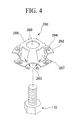
- FIG. 4 is an exploded perspective view of a first connection cap 260 and the fixing element 170 used in a battery module according to a second embodiment of the present invention.
- a first cap base 262 of the first connection cap 260 can be formed in a ring shape having a vertical opening portion.
- First indentations 263 are formed at the outermost edge portion of the first cap base 262 in a substantially semi-circular shape.
- the first cap base 262 can be joined with the electrode cap 143 (see FIG. 1 ) by using resistance welding or laser welding.
- First depressed portions 264 may be formed in the first cap base 262 so that a welding electrode can be inserted therein.
- a first cover 266 of the first connection cap 260 protrudes from the inner edge portion of the first cap base 262.
- the first cover 266 may be integrally formed in the first cap base 262, but is not so limited.
- the first cover 266 constructed as a separate member may be connected to the first cap base 262.
- Four first openings 267 are formed at the lateral portion of the first cover 266. Similar to the degassing hole 143a formed in the electrode cap 143 (see FIG. 1 ), the first openings 267 allow gas inside the rechargeable battery 105 to be exhausted to the outside when the safety member 142 is damaged.
- the four first indentations 263 are formed in the first cap base 262.
- Each of the first indentations 263 is formed between each of a pair of the first openings 267.
- the centers of the first indentations 263 may be disposed at the same line as the center of a space between each pair of the adjacent first openings 267.
- Each of shortest distances d2 between the first indentations 263 and their adjacent first openings 267 are the same.
- the shortest distance d2 can be formed according to the capacity and size of the rechargeable battery 105.
- the shortest distance d2 may be in the range of 0.6mm to 3.5mm.
- the shortest distance d2 between the first opening 267 and the first indentation 263 is preferably short.
- a stress can be concentrated on this portion.
- damage may first occur between the first indentation 263 and the first opening 267. That is, when external force is exerted, damage first occurs at a portion between the first opening 267 and the first indentation 263. Due to a buffer effect, the external forces exerted on the rechargeable battery 105 can be minimized.
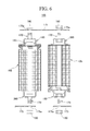
- FIG. 5 is an exploded perspective cross-sectional view of the second connection cap 360 and the rechargeable battery 105 shown in FIG. 1 .
- the second cap base 362, which has a second indentation 363, and the second connection cap 360 which includes a second cover 366 having a second opening 367, have the same or similar structure as the aforementioned first connection cap 160 described above. However, there is a slight difference in that the cap base 362 of the second connection cap 360 is fixed to the lower surface of the casing 120 of the rechargeable battery 105.
- the bolt 170 is fixed at the inner portion of the second cover 366 of the second connection cap 360.
- the nut 270 may be fixed to the inner portion of the second cover 366.
- the second connection cap 360 may be used to connect a plurality of rechargeable batteries along with the aforementioned first connection cap 160, the fixing element, and the connection member 175 (see FIG. 6 ) to be described later.
- FIG. 6 is an exploded cross-sectional view of the battery module 100 connected with a plurality of the rechargeable batteries 105.
- the adjacent rechargeable batteries 105 are separated from each other. That is, the first connection cap 160 of the first rechargeable battery 105, which is any one of the rechargeable batteries 105 described herein, and the second connection cap 360 of the second rechargeable battery 105 adjacent to the first rechargeable battery 105, are oriented in the same direction, thereby being arranged in parallel in a radius direction. Thereafter, the connection member 175 is disposed on the first connection cap 160 and the second connection cap 360.
- connection member 175 is a conductor that connects the rechargeable batteries 105.
- the connection member 175 may be manufactured in various shapes. However, in this embodiment, the connection member 175 has a rectangular plate shape. First and second through-holes 175a are formed at both edge portions of the connection member 175.
- connection member 175 can be fixed to the first and second connection caps 160 and 360 by tightening the nuts 190 on the bolts 170.
- the battery module 100 having the aforementioned structure can concentrate a stress between each opening and each indentation of the first and second connection caps 160 and 360. Thus, it is possible to protect the rechargeable batteries 105 against damage or a short circuit.
- the present invention since a stress can be exerted on first and second connection cap, it is possible to offset external forces exerted on respective rechargeable batteries constituting a battery module. Therefore, the rechargeable batteries can be protected against damage caused by the external forces exerted on the battery module. Furthermore, an electrode assembly can be prevented from damage, thereby avoiding a short circuit. In addition, the present invention can prevent explosion of the rechargeable batteries caused by damage or the occurrence of the short circuit of the rechargeable batteries. Furthermore, devices employing the rechargeable batteries can be prevented from a fire, thereby ensuring safety.
Landscapes
- Chemical & Material Sciences (AREA)
- Chemical Kinetics & Catalysis (AREA)
- Electrochemistry (AREA)
- General Chemical & Material Sciences (AREA)
- Connection Of Batteries Or Terminals (AREA)
- Battery Mounting, Suspending (AREA)
- Gas Exhaust Devices For Batteries (AREA)
- Sealing Battery Cases Or Jackets (AREA)
Applications Claiming Priority (1)
| Application Number | Priority Date | Filing Date | Title |
|---|---|---|---|
| KR1020060120546A KR100814853B1 (ko) | 2006-12-01 | 2006-12-01 | 전지 모듈 |
Publications (2)
| Publication Number | Publication Date |
|---|---|
| EP1928044A1 true EP1928044A1 (fr) | 2008-06-04 |
| EP1928044B1 EP1928044B1 (fr) | 2009-10-21 |
Family
ID=38983771
Family Applications (1)
| Application Number | Title | Priority Date | Filing Date |
|---|---|---|---|
| EP07119071A Not-in-force EP1928044B1 (fr) | 2006-12-01 | 2007-10-23 | Bouchon de connexion pour batterie rechargeable |
Country Status (6)
| Country | Link |
|---|---|
| US (1) | US8895181B2 (fr) |
| EP (1) | EP1928044B1 (fr) |
| JP (1) | JP5055090B2 (fr) |
| KR (1) | KR100814853B1 (fr) |
| CN (1) | CN100544068C (fr) |
| DE (1) | DE602007002866D1 (fr) |
Families Citing this family (13)
| Publication number | Priority date | Publication date | Assignee | Title |
|---|---|---|---|---|
| KR100814853B1 (ko) | 2006-12-01 | 2008-03-20 | 삼성에스디아이 주식회사 | 전지 모듈 |
| KR20080072443A (ko) * | 2007-02-02 | 2008-08-06 | 삼성에스디아이 주식회사 | 용접식 고정 캡 및 이를 구비한 전지 모듈 |
| US9252400B2 (en) * | 2011-09-07 | 2016-02-02 | Tesla Motors, Inc. | Battery cap assembly with high efficiency vent |
| DE102012015817B4 (de) * | 2012-08-10 | 2024-01-18 | Dr. Ing. H.C. F. Porsche Ag | Kraftfahrzeugbatterie |
| FR3018394A1 (fr) * | 2014-03-04 | 2015-09-11 | Commissariat Energie Atomique | Piece d'assemblage et de connexion electrique d'au moins deux cellules de stockage d'energie electrique |
| JP1523764S (fr) * | 2014-07-01 | 2015-05-18 | ||
| USD780118S1 (en) * | 2014-07-08 | 2017-02-28 | Wittenstein Se | Electric motor |
| US9608245B2 (en) | 2014-09-30 | 2017-03-28 | Johnson Controls Technology Company | System for providing structural integrity of a battery module |
| JP6874362B2 (ja) * | 2016-12-22 | 2021-05-19 | スズキ株式会社 | バッテリパックの保護構造 |
| KR102711972B1 (ko) | 2018-10-08 | 2024-10-02 | 삼성에스디아이 주식회사 | 배터리 팩 |
| KR102617730B1 (ko) * | 2018-10-08 | 2023-12-26 | 삼성에스디아이 주식회사 | 배터리 팩 |
| KR102220898B1 (ko) | 2018-10-17 | 2021-02-26 | 삼성에스디아이 주식회사 | 배터리 팩 |
| US20240258664A1 (en) * | 2021-10-29 | 2024-08-01 | Lg Energy Solution, Ltd. | Cylindrical battery cell, battery pack, vehicle and current collector plate |
Citations (4)
| Publication number | Priority date | Publication date | Assignee | Title |
|---|---|---|---|---|
| EP1058332A2 (fr) * | 1999-05-31 | 2000-12-06 | Sanyo Electric Co., Ltd. | Source de courant électrique |
| US20040043287A1 (en) * | 2002-03-05 | 2004-03-04 | Masashi Bando | Battery-type power supply unit |
| US20050244706A1 (en) * | 2004-04-28 | 2005-11-03 | Wu James X | Housing for a sealed electrochemical battery cell |
| WO2006112251A1 (fr) * | 2005-04-14 | 2006-10-26 | Matsushita Electric Industrial Co., Ltd. | Procede de production pour un assemblage de dispositif electrique et assemblage de dispositif electrique |
Family Cites Families (12)
| Publication number | Priority date | Publication date | Assignee | Title |
|---|---|---|---|---|
| US5578392A (en) * | 1995-02-17 | 1996-11-26 | Japan Storage Battery Co., Ltd. | Cylindrical cell, a cell pack, and a cell holder |
| JP4025928B2 (ja) | 1995-02-17 | 2007-12-26 | 株式会社ジーエス・ユアサコーポレーション | 円筒型電池及び組電池 |
| US5853912A (en) | 1996-07-10 | 1998-12-29 | Saft America, Inc. | Lithium ion electrochemical cell with safety valve electrical disconnect |
| JP2000003702A (ja) | 1998-06-15 | 2000-01-07 | Alps Electric Co Ltd | 電池の電路遮断機構 |
| JP3913384B2 (ja) | 1998-12-25 | 2007-05-09 | 三洋電機株式会社 | アルカリ蓄電池 |
| JP3723433B2 (ja) | 2000-03-30 | 2005-12-07 | 三洋電機株式会社 | 組電池およびその製造方法 |
| JP2003288952A (ja) | 2002-03-28 | 2003-10-10 | Honda Motor Co Ltd | バッテリ式電源装置 |
| KR100889769B1 (ko) * | 2002-10-22 | 2009-03-24 | 삼성에스디아이 주식회사 | 각형 리튬이차 전지와 이의 제조 방법 |
| KR100496302B1 (ko) * | 2003-05-19 | 2005-06-17 | 삼성에스디아이 주식회사 | 안전벤트를 가지는 각형 리튬 이차 전지 |
| KR100536253B1 (ko) * | 2004-03-24 | 2005-12-12 | 삼성에스디아이 주식회사 | 이차 전지 |
| JP5116235B2 (ja) * | 2006-01-23 | 2013-01-09 | 三洋電機株式会社 | 密閉型電池 |
| KR100814853B1 (ko) | 2006-12-01 | 2008-03-20 | 삼성에스디아이 주식회사 | 전지 모듈 |
-
2006
- 2006-12-01 KR KR1020060120546A patent/KR100814853B1/ko not_active IP Right Cessation
-
2007
- 2007-10-03 US US11/866,894 patent/US8895181B2/en not_active Expired - Fee Related
- 2007-10-23 EP EP07119071A patent/EP1928044B1/fr not_active Not-in-force
- 2007-10-23 DE DE602007002866T patent/DE602007002866D1/de active Active
- 2007-10-24 CN CNB2007101820474A patent/CN100544068C/zh not_active Expired - Fee Related
- 2007-10-31 JP JP2007284084A patent/JP5055090B2/ja not_active Expired - Fee Related
Patent Citations (4)
| Publication number | Priority date | Publication date | Assignee | Title |
|---|---|---|---|---|
| EP1058332A2 (fr) * | 1999-05-31 | 2000-12-06 | Sanyo Electric Co., Ltd. | Source de courant électrique |
| US20040043287A1 (en) * | 2002-03-05 | 2004-03-04 | Masashi Bando | Battery-type power supply unit |
| US20050244706A1 (en) * | 2004-04-28 | 2005-11-03 | Wu James X | Housing for a sealed electrochemical battery cell |
| WO2006112251A1 (fr) * | 2005-04-14 | 2006-10-26 | Matsushita Electric Industrial Co., Ltd. | Procede de production pour un assemblage de dispositif electrique et assemblage de dispositif electrique |
Also Published As
| Publication number | Publication date |
|---|---|
| US20080131767A1 (en) | 2008-06-05 |
| CN100544068C (zh) | 2009-09-23 |
| JP5055090B2 (ja) | 2012-10-24 |
| DE602007002866D1 (de) | 2009-12-03 |
| EP1928044B1 (fr) | 2009-10-21 |
| JP2008140773A (ja) | 2008-06-19 |
| KR100814853B1 (ko) | 2008-03-20 |
| CN101192653A (zh) | 2008-06-04 |
| US8895181B2 (en) | 2014-11-25 |
Similar Documents
| Publication | Publication Date | Title |
|---|---|---|
| EP1928044B1 (fr) | Bouchon de connexion pour batterie rechargeable | |
| EP1914820B1 (fr) | Module de batterie | |
| US7858228B2 (en) | Rechargeable battery | |
| KR100823510B1 (ko) | 전지 모듈 및 그 제조 방법 | |
| EP2254176B1 (fr) | Batterie rechargeable | |
| KR100882915B1 (ko) | 이차 전지 | |
| EP1914817B1 (fr) | Accumulateur électrochimique et module | |
| US20060024578A1 (en) | Secondary battery | |
| KR100869803B1 (ko) | 전지 모듈 | |
| US8546005B2 (en) | Cap assembly and secondary battery having the same | |
| EP3154108B1 (fr) | Support de piles et bloc-batterie le comprenant | |
| KR100913174B1 (ko) | 전지 모듈 | |
| US7754376B2 (en) | Cylindrical lithium secondary battery and method of fabricating the same | |
| KR20080043533A (ko) | 이차 전지 | |
| US20090087732A1 (en) | Secondary battery | |
| KR101121205B1 (ko) | 이차전지 | |
| US8481193B2 (en) | Battery module and method of manufacturing the same | |
| KR100814882B1 (ko) | 이차 전지 및 상기 이차 전지를 이용한 전지 모듈 | |
| KR102335696B1 (ko) | 전류차단부재 및 캡 조립체 | |
| KR101275788B1 (ko) | 전지 모듈 | |
| US20100209766A1 (en) | Secondary battery |
Legal Events
| Date | Code | Title | Description |
|---|---|---|---|
| PUAI | Public reference made under article 153(3) epc to a published international application that has entered the european phase |
Free format text: ORIGINAL CODE: 0009012 |
|
| 17P | Request for examination filed |
Effective date: 20071023 |
|
| AK | Designated contracting states |
Kind code of ref document: A1 Designated state(s): AT BE BG CH CY CZ DE DK EE ES FI FR GB GR HU IE IS IT LI LT LU LV MC MT NL PL PT RO SE SI SK TR |
|
| AX | Request for extension of the european patent |
Extension state: AL BA HR MK RS |
|
| AKX | Designation fees paid |
Designated state(s): DE FR GB HU |
|
| GRAP | Despatch of communication of intention to grant a patent |
Free format text: ORIGINAL CODE: EPIDOSNIGR1 |
|
| GRAS | Grant fee paid |
Free format text: ORIGINAL CODE: EPIDOSNIGR3 |
|
| GRAA | (expected) grant |
Free format text: ORIGINAL CODE: 0009210 |
|
| AK | Designated contracting states |
Kind code of ref document: B1 Designated state(s): DE FR GB HU |
|
| REG | Reference to a national code |
Ref country code: GB Ref legal event code: FG4D |
|
| REF | Corresponds to: |
Ref document number: 602007002866 Country of ref document: DE Date of ref document: 20091203 Kind code of ref document: P |
|
| PLBE | No opposition filed within time limit |
Free format text: ORIGINAL CODE: 0009261 |
|
| STAA | Information on the status of an ep patent application or granted ep patent |
Free format text: STATUS: NO OPPOSITION FILED WITHIN TIME LIMIT |
|
| 26N | No opposition filed |
Effective date: 20100722 |
|
| PG25 | Lapsed in a contracting state [announced via postgrant information from national office to epo] |
Ref country code: HU Free format text: LAPSE BECAUSE OF FAILURE TO SUBMIT A TRANSLATION OF THE DESCRIPTION OR TO PAY THE FEE WITHIN THE PRESCRIBED TIME-LIMIT Effective date: 20100422 |
|
| REG | Reference to a national code |
Ref country code: FR Ref legal event code: PLFP Year of fee payment: 9 |
|
| PGFP | Annual fee paid to national office [announced via postgrant information from national office to epo] |
Ref country code: FR Payment date: 20150923 Year of fee payment: 9 |
|
| PGFP | Annual fee paid to national office [announced via postgrant information from national office to epo] |
Ref country code: DE Payment date: 20151020 Year of fee payment: 9 Ref country code: GB Payment date: 20151021 Year of fee payment: 9 |
|
| REG | Reference to a national code |
Ref country code: DE Ref legal event code: R119 Ref document number: 602007002866 Country of ref document: DE |
|
| GBPC | Gb: european patent ceased through non-payment of renewal fee |
Effective date: 20161023 |
|
| REG | Reference to a national code |
Ref country code: FR Ref legal event code: ST Effective date: 20170630 |
|
| PG25 | Lapsed in a contracting state [announced via postgrant information from national office to epo] |
Ref country code: FR Free format text: LAPSE BECAUSE OF NON-PAYMENT OF DUE FEES Effective date: 20161102 Ref country code: GB Free format text: LAPSE BECAUSE OF NON-PAYMENT OF DUE FEES Effective date: 20161023 Ref country code: DE Free format text: LAPSE BECAUSE OF NON-PAYMENT OF DUE FEES Effective date: 20170503 |