EP2325658B1 - Vorrichtung und verfahren zur schätzung von batteriewiderstandseigenschaften anhand des batteriespannungsverhaltens - Google Patents
Vorrichtung und verfahren zur schätzung von batteriewiderstandseigenschaften anhand des batteriespannungsverhaltens Download PDFInfo
- Publication number
- EP2325658B1 EP2325658B1 EP09806781.2A EP09806781A EP2325658B1 EP 2325658 B1 EP2325658 B1 EP 2325658B1 EP 09806781 A EP09806781 A EP 09806781A EP 2325658 B1 EP2325658 B1 EP 2325658B1
- Authority
- EP
- European Patent Office
- Prior art keywords
- battery
- resistance
- open circuit
- mean
- voltage variation
- Prior art date
- Legal status (The legal status is an assumption and is not a legal conclusion. Google has not performed a legal analysis and makes no representation as to the accuracy of the status listed.)
- Active
Links
- 238000000034 method Methods 0.000 title claims description 18
- 238000012937 correction Methods 0.000 claims description 17
- 230000015556 catabolic process Effects 0.000 claims description 12
- 238000006731 degradation reaction Methods 0.000 claims description 12
- 238000005259 measurement Methods 0.000 claims description 6
- 238000013178 mathematical model Methods 0.000 claims description 5
- 238000013507 mapping Methods 0.000 claims description 3
- 229910052738 indium Inorganic materials 0.000 claims description 2
- 230000006870 function Effects 0.000 description 15
- 238000007599 discharging Methods 0.000 description 14
- 238000004364 calculation method Methods 0.000 description 10
- 230000003247 decreasing effect Effects 0.000 description 8
- 238000002474 experimental method Methods 0.000 description 7
- 230000000694 effects Effects 0.000 description 6
- 238000010586 diagram Methods 0.000 description 5
- 230000003679 aging effect Effects 0.000 description 3
- 230000007423 decrease Effects 0.000 description 3
- 238000012360 testing method Methods 0.000 description 3
- PXHVJJICTQNCMI-UHFFFAOYSA-N Nickel Chemical compound [Ni] PXHVJJICTQNCMI-UHFFFAOYSA-N 0.000 description 2
- 238000011160 research Methods 0.000 description 2
- UFHFLCQGNIYNRP-UHFFFAOYSA-N Hydrogen Chemical compound [H][H] UFHFLCQGNIYNRP-UHFFFAOYSA-N 0.000 description 1
- WHXSMMKQMYFTQS-UHFFFAOYSA-N Lithium Chemical compound [Li] WHXSMMKQMYFTQS-UHFFFAOYSA-N 0.000 description 1
- HBBGRARXTFLTSG-UHFFFAOYSA-N Lithium ion Chemical compound [Li+] HBBGRARXTFLTSG-UHFFFAOYSA-N 0.000 description 1
- 238000003915 air pollution Methods 0.000 description 1
- 238000004458 analytical method Methods 0.000 description 1
- OJIJEKBXJYRIBZ-UHFFFAOYSA-N cadmium nickel Chemical compound [Ni].[Cd] OJIJEKBXJYRIBZ-UHFFFAOYSA-N 0.000 description 1
- 230000001413 cellular effect Effects 0.000 description 1
- 238000003487 electrochemical reaction Methods 0.000 description 1
- 238000004880 explosion Methods 0.000 description 1
- 239000002803 fossil fuel Substances 0.000 description 1
- 229910052739 hydrogen Inorganic materials 0.000 description 1
- 239000001257 hydrogen Substances 0.000 description 1
- 230000002427 irreversible effect Effects 0.000 description 1
- 229910052744 lithium Inorganic materials 0.000 description 1
- 229910001416 lithium ion Inorganic materials 0.000 description 1
- 230000007774 longterm Effects 0.000 description 1
- 238000004519 manufacturing process Methods 0.000 description 1
- 238000012986 modification Methods 0.000 description 1
- 230000004048 modification Effects 0.000 description 1
- 229910052759 nickel Inorganic materials 0.000 description 1
- QELJHCBNGDEXLD-UHFFFAOYSA-N nickel zinc Chemical compound [Ni].[Zn] QELJHCBNGDEXLD-UHFFFAOYSA-N 0.000 description 1
- 229920000642 polymer Polymers 0.000 description 1
Images

Classifications
-
- G—PHYSICS
- G01—MEASURING; TESTING
- G01R—MEASURING ELECTRIC VARIABLES; MEASURING MAGNETIC VARIABLES
- G01R31/00—Arrangements for testing electric properties; Arrangements for locating electric faults; Arrangements for electrical testing characterised by what is being tested not provided for elsewhere
- G01R31/36—Arrangements for testing, measuring or monitoring the electrical condition of accumulators or electric batteries, e.g. capacity or state of charge [SoC]
- G01R31/389—Measuring internal impedance, internal conductance or related variables
-
- G—PHYSICS
- G01—MEASURING; TESTING
- G01R—MEASURING ELECTRIC VARIABLES; MEASURING MAGNETIC VARIABLES
- G01R19/00—Arrangements for measuring currents or voltages or for indicating presence or sign thereof
-
- G—PHYSICS
- G01—MEASURING; TESTING
- G01R—MEASURING ELECTRIC VARIABLES; MEASURING MAGNETIC VARIABLES
- G01R31/00—Arrangements for testing electric properties; Arrangements for locating electric faults; Arrangements for electrical testing characterised by what is being tested not provided for elsewhere
- G01R31/36—Arrangements for testing, measuring or monitoring the electrical condition of accumulators or electric batteries, e.g. capacity or state of charge [SoC]
- G01R31/367—Software therefor, e.g. for battery testing using modelling or look-up tables
Definitions
- the present invention relates to apparatus and method for estimating resistance characteristics of a battery, and more particularly to apparatus and method for estimating resistance characteristics of a battery based on an open circuit voltage of the battery.
- the research for quantitatively evaluating the aging effect according to the use of battery is actively performed.
- electrochemical parameters whose properties are changed according to a using time of the battery are needed, and a battery resistance may be considered as one of such parameters.
- the battery resistance tends to increase according to a using time of the battery, so the aging effect of a battery may be quantitatively evaluated by measuring a resistance of the battery and then comparing it with an initial resistance value when the battery was produced.
- the battery resistance cannot be directly measured while the battery is charged or discharged.
- a voltage of a battery and a charging/discharging current were measured, and then a battery resistance was indirectly measured according to the Ohm's law.
- the battery voltage shows deviation from an actual voltage due to the IR drop effect, and the battery current also has a measurement error, so the resistance simply calculated according to the Ohm's law has an error in comparison to an actual resistance.
- the IR drop effect means a phenomenon that a voltage is rapidly changed when a battery starts being discharged in connected to a load or starts being charged from an external power source.
- a battery voltage rapidly decreases when discharging is initiated, and a voltage rapidly increases when charging is initiated.
- EP 1 688 754 discloses a battery management apparatus and US 5 703 469 relates to a system for determining battery conditions.
- the present invention is designed to solve the problems of the prior art, and therefore it is an object of the present invention to provide apparatus and method for estimating battery resistance characteristics with high accuracy.
- the present invention provides an apparatus for estimating resistance characteristics of a battery based on a battery voltage variation pattern, which includes a data storing manager for obtaining and storing battery voltage, current and temperature data from a voltage sensor, a current sensor and a temperature sensor, which are coupled to a battery, whenever a resistance characteristic is estimated; an open circuit voltage calculator for calculating a battery open circuit voltage from a battery voltage variation pattern measured at the present and in the past; a weighted mean resistance calculator for calculating a battery resistance parameter from a battery current and a difference between the battery open circuit voltage and a battery voltage, and calculating a weighted mean resistance from battery resistance parameters calculated at the present and in the past; a weighted mean resistance convergence calculator for calculating a weighed mean resistance convergence value by repeatedly calculating a weighted mean sequence using the weighted mean resistance as an initial condition; and a resistance characteristic estimator for estimating a battery resistance from the weighted mean resistance convergence value.
- the resistance characteristic estimator may estimate the weighted mean resistance convergence value as a battery resistance.
- the resistance characteristic estimator may estimate a battery resistance by mapping a battery resistance corresponding to the calculated weighted mean resistance convergence value from a look-up table defining a battery resistance for each weighted mean resistance convergence value.
- the resistance characteristic estimator may estimate a battery resistance by inputting the calculated weighted mean resistance convergence value to a function using the weighted mean resistance convergence value and the battery resistance as an input parameter and an output parameter, respectively.
- the resistance characteristic estimator may estimate a battery resistance by relatively comparing the calculated weighted mean resistance convergence value with a weighted mean resistance convergence value corresponding to an initial battery resistance value when a battery was produced.
- the resistance characteristic estimator may estimate a relative ratio of the estimated battery resistance to an initial battery resistance value based on an allowable maximum resistance as a parameter representing battery resistance degradation.
- the open circuit voltage calculator may include an open circuit voltage variation calculating unit for calculating an open circuit voltage variation from a variation pattern of the stored battery voltages measured at the present and in the past by applying a mathematic model defining a correlation between a battery voltage variation pattern and an open circuit voltage variation, and estimating an open circuit voltage variation at a present stage by reflecting a correction factor corresponding to battery temperature on the calculated open circuit voltage variation; and an open circuit voltage estimating unit for estimating a battery open circuit voltage at the present stage by reflecting the estimated open circuit voltage variation to a battery open circuit voltage estimated at a last stage.
- the open circuit voltage estimating unit may correct an open circuit voltage by adding a difference between a weight mean value (a greater weight is endowed as battery voltage is measured earlier) for present and previous battery voltages and an open-circuit voltage at a last stage to the estimated open-circuit voltage at a present stage.
- the previous battery voltage may be a battery voltage at a last stage.
- the estimated open circuit voltage variation may be calculated by multiplying the calculated open circuit voltage variation by the correction factor corresponding to temperature.
- the battery voltage variation pattern may include at least voltages V n , V n-1 and V n-2 measured at a present stage, at a last stage and at the stage before last.
- the mathematical model may be defined by a mathematical operation between a battery voltage variation between a present stage and a previous stage and a pattern function defined by each voltage of the battery voltage variation pattern.
- the correction factor may be calculated by inputting a battery temperature into a mathematical model using the battery temperature (T) as an input parameter and the correction factor of the battery open circuit voltage variation as an output parameter.
- the present invention also provides a method for estimating resistance characteristics of a battery based on a battery voltage variation pattern, which includes obtaining and storing battery voltage, current and temperature data from a voltage sensor, a current sensor and a temperature sensor, which are coupled to a battery, whenever a resistance characteristic is estimated; calculating a battery open circuit voltage from a battery voltage variation pattern measured at the present and in the past; calculating a battery resistance parameter from a battery current and a difference between the battery open circuit voltage and a battery voltage, and calculating a weighted mean resistance from battery resistance parameters calculated at the present and in the past; calculating a weighed mean resistance convergence value by repeatedly calculating a weighted mean sequence using the weighted mean resistance as an initial condition; and estimating a battery resistance from the weighted mean resistance convergence value.
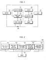
- FIG. 1 is a schematic view showing an apparatus for estimating resistance characteristics of a battery based on a battery voltage variation pattern according to an embodiment of the present invention.
- the apparatus for estimating resistance characteristics of a battery based on a battery voltage variation pattern is connected between a battery 100 and a load 107, and includes a voltage sensor 101, a temperature sensor 102, a current sensor 103, a memory 104 and a microcontroller 105.
- the voltage sensor 101 measures a battery voltage under the control of the microcontroller 105 at each resistance characteristic estimation and outputs the battery voltage to the microcontroller 105.
- the measured battery voltage is different from an actual voltage of the battery due to the IR drop effect.
- the temperature sensor 102 measures a battery temperature under the control of the microcontroller 105 at each resistance characteristic estimation and outputs the battery temperature to the microcontroller 105.
- the current sensor 103 measures a battery current flowing through a current sensing resistance 108 under the control of the microcontroller 105 at each resistance characteristic estimation and outputs the battery current to the microcontroller 105.
- the memory 104 stores programs required for estimating resistance characteristics of a battery, various data needed in advance for estimating battery resistance and resistance degradation by using the battery resistance characteristic estimating program, battery voltage, temperature and current data measured by the voltage sensor 101, the temperature sensor 102 and the current sensor 103, and various calculation values occurring while the battery resistance characteristic estimating program estimates battery resistance and resistance degradation.
- the microcontroller 105 receives battery voltage, temperature and current data from the voltage sensor 101, the temperature sensor 102 and the current sensor 103 at each estimation of resistance characteristics of the battery 100 and stores the data in the memory 104. Also, the microcontroller 105 reads and executes the battery resistance characteristic estimating program from the memory 104, estimates battery resistance and resistance degradation of a battery and stores the estimated data in the memory 104, and outputs the estimated battery resistance and resistance degradation through a display 106 as necessary.
- the kind of the battery 100 is not specially limited, and it may adopt lithium ion batteries, lithium polymer batteries, nickel cadmium batteries, nickel hydrogen batteries, nickel zinc batteries and so on, which are rechargeable and whose charging state should be considered.
- the kind of the load 107 is not specially limited, and it may be portable electronic devices such as video cameras, mobile phones, portable PC (Personal Computer), PMP (Portable Multimedia Player) and MP3 players, motors of electric vehicles or hybrid vehicles, DC to DC converters, and so on.
- portable electronic devices such as video cameras, mobile phones, portable PC (Personal Computer), PMP (Portable Multimedia Player) and MP3 players, motors of electric vehicles or hybrid vehicles, DC to DC converters, and so on.
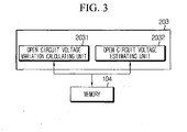
- FIG. 2 is a block diagram showing a battery resistance characteristic estimating program according to an embodiment of the present invention.
- the battery resistance characteristic estimating program 200 is executed by the microcontroller 105 and includes a data storing manager 201, an open circuit voltage calculator 202, a weighted mean resistance calculator 203, a weighted mean resistance convergence calculator 204 and a resistance characteristic estimator 205.
- the data storing manager 201 receives voltage V n , temperature T n and current I n of the battery from the voltage sensor 101, the temperature sensor 102 and the current sensor 103, shown in FIG. 1 , at each resistance characteristic estimation and stores the data in the memory 104.
- n is the number of measurement times of voltage, temperature and current, and it is identical to the number of resistance characteristic estimation times.
- the open circuit voltage calculator 202 calculates an open circuit voltage variation ⁇ OCV n of a battery using a battery voltage variation pattern, corrects the calculated battery open circuit voltage variation by applying a correction factor according to temperature thereto, and calculates a battery open circuit voltage OCV n at a present stage by reflecting the corrected battery open circuit voltage variation on a previously calculated open circuit voltage OCV n-1 .
- the process of calculating the open circuit voltage variation ⁇ OCV n and the process of correcting the open circuit voltage variation ⁇ OCV n according to temperature will be explained in detail later.
- the open circuit voltage calculator 202 stores the calculated ⁇ OCV n in the memory 104.
- the weighted mean resistance calculator 203 calculates a weighted mean resistance R mean n using the following Math Figure 1 .
- R mean n R n - 1 ⁇ weight + R n ⁇ weight + 1
- R n - 1 V n - 1 - OCV n - 1 ⁇ I n - 1
- R n V n - OCV n ⁇ I n
- R n and R n-1 are battery resistance parameters respectively calculated at n th time and n-1 th time
- V n and V n-1 are battery voltages respectively measured at n th time and n-1 th time
- OCV n and OCV n-1 are open circuit voltages of a battery, respectively calculated at n th time and n-1 th time
- I n and I n-1 are battery currents respectively measured at n th time and n-1 th time
- n is an integer of 2 or more
- weight is a sufficiently great value, for example 5000 or more.
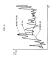
- FIG. 6 is a graph showing V n periodically measured while charging/discharging a battery in a predetermined pattern and OCV n periodically estimated using the battery voltage variation pattern.
- the measured battery voltage V n is varied more abruptly in comparison to the estimated OCV n . It is caused by the IR drop effect occurring at measuring a battery voltage, so the absolute difference between the measured voltage V n and the estimated voltage OCV n is corresponding to a value obtained by multiplying a battery current I n by a battery resistance R n .
- the battery resistance parameter R n can be considered as representing a resistance characteristic of a battery at the time of measuring V n .
- FIG. 7 is a graph showing a variation pattern of weighted mean resistances R mean 1 , R mean 2 , R mean 3 , R mean 4 , R mean 5 ..., which are periodically calculated according to time passage based on different conditions of the resistance parameter R 1 , while performing a charging/discharging test to a battery whose resistance is already known.
- a graph A represents a case that the resistance parameter R 1 is set as an actual resistance
- a graph B represents a case that the resistance parameter R 1 is set higher than an actual resistance
- a graph C represents a case that the resistance parameter R 1 is set lower than an actual resistance.
- the weighted mean resistance is converged to an actual resistance value as time goes.
- a convergence of the weighted mean resistance may be used as a parameter for estimating a battery resistance.
- the convergence of weighted mean resistance can be obtained through a long-term charging/discharging experiment.
- a weighted mean resistance is obtained at a specific time point, it is impossible to know which value the weighted mean resistance would be converged to.
- a convergence of the weighted mean resistance is estimated using a weighted mean sequence in which the obtained weighted mean resistance is an initial condition.
- the weighted mean resistance convergence calculator 204 calculates a weighted mean resistance according to a weighted mean sequence using the weighted mean resistance R mean n , calculated by the weighted mean resistance calculator 203, as an initial condition by using the following Math Figure 2 , and this calculation is repeated sufficiently many times. In this way, the weighted mean resistance convergence calculator 204 obtains a convergence R mean n of the weighted mean resistance and stores it in the memory 104.
- R mean n means a converged value of R mean n .
- k is an integer of 1 or more.
- the weighted mean sequence is calculated as much as a large number over several thousands.
- An initial convergence R mean 1 of the weighted mean resistance may refer to a value that is set at the time of production of the battery and stored in the memory 104.
- the weighted mean resistance R mean n tends to be converged to an actual resistance value without depending on an initial condition R 1 of the resistance parameter, as shown in FIG. 7 .
- the initial value R mean n 0 is preferably set as a convergence value R mean n-1 obtained in a previous stage or an initial battery resistance value when the battery was produced. In this case, the number of sequence calculations may be reduced until the weighted mean resistance is converged to an actual resistance value, so the weighted mean resistance may be rapidly converged to an actual resistance value.
- the resistance characteristic estimator 205 reads the weighted mean resistance convergence value R mean n from the memory 104, and then the resistance characteristic estimator 205 estimates a battery resistance R ⁇ n and then stores it in the memory 104.
- R ⁇ n means a battery resistance estimated at an n th resistance estimating.
- the resistance characteristic estimator 205 may estimate the weighted mean resistance convergence value R mean n into the battery resistance R ⁇ n as it is.
- the resistance characteristic estimator 205 may estimate a battery resistance R ⁇ n corresponding to the weighted mean resistance convergence value R mean n using correlation between the weighted mean resistance convergence value and the battery resistance.
- This correlation may be a look-up table defining battery resistance for each weighted mean resistance convergence value.
- the correlation may be a function using a weighted mean resistance convergence value and a battery resistance as an input parameter and an output parameter, respectively.
- the correlation is obtained through charging/discharging tests for a battery.
- weighted mean resistance convergence values are obtained while charging/discharging experiments are conducted under the same conditions for a long time to a sufficiently large amount of batteries whose actual resistance are already known in a wide range.
- battery resistances corresponding to the weighted mean resistance convergence values obtained through the experiments are configured into a look-up table.
- a functional relation between weighted mean resistance convergence values and battery resistances may be obtained through a numerical analysis using the weighted mean resistance convergence values obtained through the experiments and the battery resistances as input parameters and output parameters, respectively.
- the resistance characteristic estimator 205 may estimate a battery resistance R ⁇ n by relatively comparing the weighted mean resistance convergence value R mean n calculated by the weighted mean resistance convergence calculator 204 with the weighted mean resistance convergence value corresponding to an initial resistance value when the battery was produced, stored in the memory 104.
- the resistance characteristic estimator 205 may calculate a relative ratio of the estimated battery resistance R ⁇ n to an initial battery resistance value R initial according to the following Math Figure 3 after estimating a battery resistance R ⁇ n , and then store the calculated result in the memory 104 as SOH R n that is a parameter representing resistance degradation of the battery.
- SOH R n R limit - R ⁇ u ⁇ R limit - R initial ⁇ 100
- SOH R n represents a present battery resistance as a relative ratio to an initial battery resistance value.
- the battery resistance tends to increasing as time goes, so SOH R n becomes a parameter to determine how much battery life remains after the battery was initially used.
- SOH R n may be utilized to control a charging/discharging capacity of a battery. For example, if SOH R n is decreased, a charging capacity and a discharging capacity of a battery may be decreased accordingly. In this case, it is possible to effectively prevent a battery from being overcharged or overdischarged by charging or discharging the battery suitably for its resistance.
- the resistance characteristic estimator 205 may output the estimated SOH R n to the display 106.
- the display 106 is coupled to the microcontroller 105 through an interface.
- the resistance characteristic estimator 205 outputs SOH R n to the display 106 through the interface. Then, the display 106 visually displays SOH R n such that a user may recognize it. SOH R n may be displayed as texts directly or as graphs.
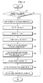
- FIG. 3 is a block diagram showing an open circuit voltage calculator 202 for estimating a battery open circuit voltage using a battery voltage variation pattern according to the present invention in more detail.
- the open circuit voltage calculator 203 includes an open circuit voltage variation calculating unit 2031 and an open circuit voltage estimating unit 2032.
- the open circuit voltage variation calculating unit 2031 calculates an open circuit voltage variation based on an open circuit voltage at a last stage using a battery voltage variation pattern in order to calculate a present battery open circuit voltage. In other words, the open circuit voltage variation calculating unit 2031 calculates how much a battery open circuit voltage at a present stage is changed based on the open circuit voltage at a last stage.
- the open circuit voltage variation calculating unit 2031 reads a battery voltage V n measured at a present resistance characteristic estimation, a battery voltage V n-1 measured at a last resistance characteristic estimation and a battery temperature T n measured at a present resistance characteristic estimation from the memory 104. After that, the open circuit voltage variation calculating unit 2031 calculates an open circuit voltage variation ⁇ OCV n according to the following Math Figure 4 .
- G(V) is an open circuit voltage variation operation function for mapping a battery voltage variation 'V n -V n-1 ' into an open circuit voltage variation ⁇ OCV n
- F(T) is an open circuit voltage correction function for correcting the open circuit voltage variation ⁇ OCV n by reflecting an open circuit voltage change according to temperature.
- G(V) is a function not for converting a battery voltage variation into an open circuit voltage variation as it is, but for converting the battery voltage variation into the open circuit voltage variation by correcting an error of battery voltage caused by IR drop (namely, a difference between a measured voltage and an actual voltage).
- G(V) decreases the battery voltage variation and then outputs the decreased battery voltage variation as a battery open circuit voltage variation.
- G(V) outputs the battery voltage variation as a battery open circuit voltage variation as it is.
- G(V) amplifies the battery voltage variation slightly and then outputs the slightly amplified battery voltage variation as a battery open circuit voltage variation.
- G(V) may be obtained by mathematically modeling a correlation between a battery voltage variation pattern and an open circuit voltage variation corresponding thereto under a certain temperature condition.
- the mathematical modeling function may be obtained by analyzing a correlation existing between a variation pattern of battery voltages V n , V n-1 and V n-2 and an open circuit voltage variation ⁇ OCV n corresponding thereto under a laboratory condition allowing measurement of battery voltage and battery open circuit voltage.
- the number of battery voltages configuring a variation pattern of battery voltages may be extended to four or more.
- G(V) may be generalized as in the following Math Figure 5 .
- G V V n - V n - 1 ⁇ g ⁇ V n V n - 1 V n - 2 ⁇
- g(V n , V n-1 , V n-2 , ...) is a pattern function defining a variation pattern of battery voltages measured at each resistance characteristic estimation.
- the symbol '...' means that the pattern function may be defined using at least three battery voltages, including a battery voltage measured at a present stage.
- the pattern function is defined by analyzing a correlation between a plurality of battery voltage variations and battery open circuit voltage variations, experimentally obtained.
- the function g may be defined as a relative ratio of a voltage variation at a last stage to a voltage variation at a present stage.
- the present invention is not limited to any specific math figure of the pattern function g.
- F(T) corrects the open circuit voltage variation, calculated by G(V), according to a temperature condition.
- F(T) is a function for correcting an open circuit voltage variation calculated by G(V) in case a battery temperature is different from a standard temperature set as a calculation condition of G(V).
- F(T) may be obtained by analyzing a correlation between a battery voltage variation pattern and a battery open circuit voltage variation while changing temperature at regular intervals.
- F(T) may be obtained by measuring a changing amount of a battery open circuit voltage variation ⁇ OCV n in comparison to ⁇ OCV n obtained at a standard temperature and then applying a mathematical modeling for the temperature and the changing amount of ⁇ OCV n by using the temperature T and the changing amount ⁇ OCV n as an input parameter and an output parameter, respectively.
- the obtained F(T) becomes a function outputting a correction factor of a battery open circuit voltage variation using the battery temperature T as an input parameter.
- a look-up table with correction factors depending on each T value and stores the look-up table in the memory 104 such that a correction factor for each temperature, stored in the look-up table, may be referred to for obtaining a correction factor used to correct a battery open circuit voltage variation.
- the open circuit voltage estimating unit 2032 reads an open circuit voltage OCV n-1 calculated at a last resistance characteristic estimation from the memory 104, and then adds the open circuit voltage variation ⁇ OCV n calculated by the open circuit voltage variation calculating unit 2031 to OCV n-1 to calculate an open circuit voltage OCV n and stores it in the memory 104.
- the open circuit voltage estimating unit 2032 calculates a weighted mean value V n (meanvalue) between a battery voltage V n and a battery voltage measured at a previous stage through the following Math Figure 6 .
- a k is decreased as k increases.
- a k may have a value starting from 100 and decreased by 1.
- a 1 *V 1 +A 2 *V 2 + ⁇ +A k-2 *V k-2 (3 ⁇ k ⁇ n) may be omitted. Even in this case, the changing tendency of A k is maintained as above.
- 90 and 10 may be endowed to A n-1 and A n , respectively.
- the open circuit voltage estimating unit 2032 may correct the open circuit voltage once again by adding a difference between the calculated weighted mean value V n (meanvalue) and the open circuit voltage OCV n-1 to the calculated open circuit voltage OCV n for additional correction. If the weighted mean value V n (meanvalue) is calculated and used for correcting an open circuit voltage additionally, a calculation error of the open circuit voltage may be decreased though a voltage output from the battery 100 is abnormally changed. If the open circuit voltage is completely corrected using the weighted mean value V n (meanvalue) , the open circuit voltage estimating unit 2032 stores the corrected open circuit voltage OCV n in the memory 104.
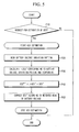
- FIG. 4 is a flowchart illustrating a method for estimating battery resistance characteristics based on a battery voltage variation pattern according to the present invention.
- each step is executed by the microcontroller 105 shown in FIG. 1 .
- step S10 it is determined whether there is a request for resistance characteristic estimation of a battery.
- the resistance characteristic estimation request may be input from the outside or automatically generated by a battery resistance characteristic estimating program.
- a battery resistance parameter R n-1 and a weighted mean resistance convergence value R mean n-1 , obtained at a last resistance characteristic estimation are read from the memory.
- V n , T n and I n are measured using the voltage sensor, the temperature sensor and the current sensor.
- a battery open circuit voltage OCV n is estimated by means of a battery voltage variation pattern, and a battery resistance parameter R n is calculated from V n , I n and OCV n .
- an initial condition R mean n 1 of the weighted mean sequence is obtained from R n-1 and R n .
- the Math Figure 2 is used when calculating R mean n 1 .
- the weighted mean sequence is repeatedly calculated as much as a sufficient number using the initial conditions R mean n 1 and R mean n-1 to calculate a convergence value R mean n of the weighted mean resistance.
- the Math Figure 2 is used when calculating R mean n .
- R mean n-1 may be substituted with a preset R mean 1 .
- R mean 1 may be set with an initial battery resistance value when the battery was initially produced.
- a battery resistance R ⁇ n is estimated from the convergence value R mean n of the weighted mean resistance.
- the battery resistance R ⁇ n may be estimated to be identical to the convergence value R mean n of the weighted mean resistance.
- a battery resistance R ⁇ n corresponding to the convergence value R mean n of the weighted mean resistance may be estimated using the correlation between the convergence value of the weighted mean resistance and the battery resistance. The correlation may be a look-up table defining battery resistance for each convergence value of the weighted mean resistance or a function using the convergence value of the weighted mean resistance and the battery resistance as an input parameter and an output parameter, respectively.
- a battery resistance may be estimated based on an initial battery resistance value by relatively comparing the convergence value of the weighted mean resistance corresponding to the initial battery resistance value with the weighted mean convergence value R mea n n calculated in the step S60.
- the initial battery resistance value is increased as much as an increment ratio of the weighted mean convergence value, and the increased value may be estimated as a battery resistance.
- a relatively increment of the estimated battery resistance R ⁇ n is calculated based on the initial battery resistance value R initial , and SOH R n is estimated by means of the calculated relative increment ratio.
- the estimated SOH R n is stored in the memory 104 or output to the display 106.
- the relative increment ratio is preferably calculated based on an allowable maximum resistance R limit according to the Math Figure 3 .
- FIG. 5 is a flowchart illustrating a process for estimating an open circuit voltage OCV n based on a battery voltage variation pattern in the step S40 of FIG. 4 .
- each step is executed by the microcontroller 105 shown in FIG. 1 .
- step P 10 it is determined whether there is a request for estimation of an open circuit voltage OCV n .
- the request for estimation may be input from the outside or automatically generated according to a program algorithm.
- an open circuit voltage estimating step is executed. If there is no request for estimation of OCV n , the process is terminated.
- a battery voltage variation pattern stored in the memory is read.
- the battery voltage variation pattern includes at least V n , V n-1 and V n-2 .
- an open circuit voltage variation ⁇ OCV n is calculated by means of the battery voltage variation pattern and a battery temperature.
- the calculation method for an open circuit voltage variation ⁇ OCV n is already explained above.
- V 1 and V 2 as well as OCV 1 and OCV 2 are initialized into battery voltages in an unloaded state, measured right before a battery is connected to a load.
- V 1 and V 2 as well as OCV 1 and OCV 2 are set as battery voltages measured when the vehicle starts using a key.
- the open circuit voltage variation ⁇ OCV n is added to a last open circuit voltage OCV n-1 to calculate a present open circuit voltage OCV n .
- a weighted mean value of a present battery voltage V n and a last battery voltage V n-1 is calculated, and a difference between the calculated weighted mean value and the last open circuit voltage OCV n-1 is added to the present open circuit voltage OCV n to additionally correct the open circuit voltage OCV n .
- the calculation method for weight mean value is already explained above.
- the estimated open circuit voltage OCV n is stored in the memory 104.
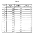
- FIG. 8 is a table showing an actual resistance, an estimated resistance and an error of the estimated resistance in comparison to the actual resistance for each of twelve batteries selected for experiments.
- the battery resistance estimated according to the present invention is within the range of 3% in comparison to an actual resistance.
- the present invention ensures estimation of battery resistance with high accuracy, and also enables to accurately estimate battery resistance degradation that is a parameter capable of being calculated from the battery resistance.
- battery resistance characteristics may be accurately estimated by simple sequence calculation.
- the accurately estimated battery resistance may be applied in various ways, for example to estimate a time for exchange of a battery.
- the present invention may prevent overcharging or overdischarging, thereby improving safety of a battery.
Landscapes
- Physics & Mathematics (AREA)
- General Physics & Mathematics (AREA)
- Secondary Cells (AREA)
- Measurement Of Resistance Or Impedance (AREA)
Claims (12)
- Vorrichtung zum Bestimmen von Widerstandseigenschaften einer Batterie, die aus der Gruppe bestehend aus Batteriewiderstand und Batteriewiderstandsverschlechterung basierend auf einem Batteriespannungsänderungsmuster ausgewählt werden, wobei die Vorrichtung Folgendes umfasst:- eine Datenspeicherverwaltung, die dafür konfiguriert ist, eine Batteriespannung Vn, einen Batteriestrom In und eine Batterietemperatur Tn von einem Spannungssensor, einem Stromsensor und einem Temperatursensor, die bei jeder Widerstandseigenschaftsschätzung mit einer Batterie verbunden sind, zu erhalten und zu speichern, wobei n die Anzahl der Messungen von Spannung, Temperatur und Strom ist und identisch mit der Anzahl der Schätzungszeiten der Widerstandseigenschaften ist;- einen Leerlaufspannungsrechner, der Folgendes aufweist:eine Einheit zur Berechnung der Leerlaufspannungsänderung, die dafür konfiguriert ist, eine Leerlaufspannungsänderung aus einem Änderungsmuster der gespeicherten Batteriespannungen, die momentan und zuvor gemessen werden, durch Anwenden eines mathematischen Modells, das einen Zusammenhang zwischen einem Batteriespannungsänderungsmuster und einer Leerlaufspannungsänderung definiert, zu berechnen und eine Leerlaufspannungsänderung zu einem momentanen Zeitpunkt durch Anwenden eines Korrekturfaktors entsprechend der Temperatur auf die berechnete Leerlaufspannungsänderung zu schätzen; und eine Einheit zum Schätzen der Leerlaufspannung, die dafür konfiguriert ist, eine Leerlaufspannung, OCV, zu dem momentanen Zeitpunkt durch Addieren der geschätzten OCV-Änderung zu der OCV, die zu dem letzten Zeitpunkt geschätzt wird, zu schätzen,wobei das Batteriespannungsänderungsmuster mindestens die Batteriespannungen Vn, Vn-1 und Vn-2 aufweist, die zu einem momentanen Zeitpunkt, zu einem letzten Zeitpunkt und zu dem Zeitpunkt vor dem letzten gemessen werden,die geschätzte Leerlaufspannungsänderung durch Multiplizieren der berechneten Leerlaufspannungsänderung mit dem Korrekturfaktor entsprechend der Temperatur berechnet wird, unddas mathematische Modell durch eine mathematische Operation zwischen einer Batteriespannungsänderung zwischen einem momentanen Zeitpunkt und einem vorherigen Zeitpunkt und einer Musterfunktion definiert ist, die durch jede Spannung des Batteriespannungsänderungsmusters definiert ist- einen Rechner für das gewichtete Mittel des Widerstands, der dafür konfiguriert ist, einen Batteriewiderstandsparameter durch Dividieren einer Differenz zwischen der Leerlaufspannung und der Batteriespannung zu dem momentanen Zeitpunkt durch einen Batteriestrom zu dem momentanen Zeitpunkt zu berechnen und ein gewichtetes Mittel für Batteriewiderstandsparameter, die zu dem momentanen Zeitpunkt und zu dem letzten Zeitpunkt berechnet werden, als ein gewichtetes Mittel des Widerstands (Rmean n) zu berechnen;- einen Rechner für die Konvergenz des gewichteten Mittels des Widerstands, der dafür konfiguriert ist, einen Konvergenzwert Rmean n von einer Folge des gewichteten Mittels zu berechnen, die als ein gewichtetes Mittel zwischen gewichteten Mitteln der Widerstände (Rmean n k-1, Rmean n k) in Reihe in der Folge des gewichteten Mittels definiert ist, wobei das berechnete gewichtete Mittel des Widerstands eine Anfangsbedingung (Rmean n 1) der Folge des gewichteten Mittels ist; und- ein Widerstandseigenschaftsschätzer, der dafür konfiguriert ist, einen Batteriewiderstand aus dem Konvergenzwert zu schätzen.
- Vorrichtung zum Schätzen von Widerstandseigenschaften einer Batterie basierend auf einem Batteriespannungsänderungsmuster nach Anspruch 1,
wobei die Widerstandseigenschaftsschätzvorrichtung dafür konfiguriert ist, den Konvergenzwert als den Batteriewiderstand zu schätzen. - Vorrichtung zum Schätzen von Widerstandseigenschaften einer Batterie, basierend auf einem Batteriespannungsänderungsmuster nach Anspruch 1,
wobei die Widerstandseigenschaftsschätzvorrichtung dafür konfiguriert ist, den Batteriewiderstand durch Zuordnen des Batteriewiderstands entsprechend dem berechneten Konvergenzwert aus einer Wertetabelle zu schätzen, wodurch ein Batteriewiderstand für jeden Konvergenzwert definiert wird. - Vorrichtung zum Schätzen von Widerstandseigenschaften einer Batterie, basierend auf einem Batteriespannungsänderungsmuster nach Anspruch 1, wobei die Widerstandseigenschaftsschätzvorrichtung dafür konfiguriert ist, den Batteriewiderstand durch Eingeben des berechneten Konvergenzwerts in eine vorbestimmte Funktion unter Verwendung eines Konvergenzwerts und eines Batteriewiderstands jeweils als einen Eingabeparameter und einen Ausgabeparameter zu schätzen.
- Vorrichtung zum Schätzen von Widerstandseigenschaften einer Batterie, basierend auf einem Batteriespannungsänderungsmuster nach Anspruch 1,
wobei die Widerstandseigenschaftsschätzvorrichtung dafür konfiguriert ist, den Batteriewiderstand durch relatives Vergleichen des berechneten Konvergenzwerts mit einem Konvergenzwert, der einem anfänglichen Batteriewiderstandswert, als die Batterie hergestellt wurde, entspricht, zu schätzen. - Vorrichtung zum Schätzen von Widerstandseigenschaften einer Batterie basierend auf einem Batteriespannungsänderungsmuster nach Anspruch 1, wobei der Rechner für das gewichtete Mittel des Widerstands dafür konfiguriert ist, das gewichtete Mittel des Widerstands (Rmean n) gemäß der folgenden mathematischen Darstellung zu berechnen:


wobei Rn und Rn-1 Batteriewiderstandsparameter sind, die jeweils zu dem momentanen Zeitpunkt (Zeit n) und dem letzten Zeitpunkt (Zeit n-1) berechnet werden,
wobei Vn und Vn-1 Batteriespannungen sind, die jeweils zum momentanen Zeitpunkt (Zeit n) und zum letzten Zeitpunkt (Zeit n-1) gemessen werden,
wobei OCVn und OCVn-1 Leerlaufspannungen einer Batterie sind, die jeweils zum momentanen Zeitpunkt (Zeit n) und zum letzten Zeitpunkt (Zeit n-1) gemessen werden, und
wobei In und In-1 Batterieströme sind, die jeweils zum momentanen Zeitpunkt (Zeit n) und zum letzten Zeitpunkt (Zeit n-1) gemessen werden. - Vorrichtung zum Schätzen von Widerstandseigenschaften einer Batterie basierend auf einem Batteriespannungsänderungsmuster nach Anspruch 1,
wobei der Rechner für die Konvergenz des gewichteten Mittels des Widerstands dafür konfiguriert ist, den Konvergenzwert (Rmean n) gemäß der folgenden Folge des gewichteten Mittels (k ist 1 oder mehr) zu berechnen:
wobei eine Anfangsbedingung (Rmean n 1) der Folge des gewichteten Mittels durch die folgende Bedingung festgelegt ist:
wobei Rmean n 0 als ein Konvergenzwert zum letzten Zeitpunkt oder als ein anfänglicher Batteriewiderstandswert festgelegt ist. - Vorrichtung zum Schätzen von Widerstandseigenschaften einer Batterie, basierend auf einem Batteriespannungsänderungsmuster nach Anspruch 1, wobei die Widerstandseigenschaftsschätzvorrichtung dafür konfiguriert ist, ein relatives Verhältnis des geschätzten Batteriewiderstands zu einem anfänglichen Batteriewiderstandswert, basierend auf einem zulässigen Maximalwiderstand als ein Parameter, der die Batteriewiderstandsdegradation darstellt, zu schätzen.
- Vorrichtung zum Schätzen von Widerstandseigenschaften einer Batterie basierend auf einem Batteriespannungsänderungsmuster nach Anspruch 1,
wobei die Einheit zum Schätzen der Leerlaufspannung dafür konfiguriert ist, die geschätzte OCV durch Addieren einer Differenz zwischen einem Mittelwert des Gewichts (ein höheres Gewicht wird durch vorheriges Messen einer Batteriespannung erzeugt) für die Batteriespannungen, die zum momentanen Zeitpunkt und zu einem vorherigen Zeitpunkt gemessen werden, und der OCV, die zum letzten Zeitpunkt gemessen wird, zu der OCV, die zu dem momentanen Zeitpunkt geschätzt wird, zu korrigieren. - Vorrichtung zum Schätzen von Widerstandseigenschaften einer Batterie, basierend auf einem Batteriespannungsänderungsmuster nach Anspruch 9,
wobei die Batteriespannung, die zum vorherigen Zeitpunkt gemessen wird, die Batteriespannung ist, die zum letzten Zeitpunkt gemessen wird. - Vorrichtung zum Schätzen von Widerstandseigenschaften einer Batterie basierend auf einem Batteriespannungsänderungsmuster nach Anspruch 1,
wobei der Korrekturfaktor durch Eingeben der Batterietemperatur in ein vorbestimmtes mathematisches Modell unter Verwendung einer Batterietemperatur (T) als ein Eingabeparameter und eines Korrekturfaktors als ein Ausgabeparameter berechnet wird. - Verfahren zur Bestimmung von Widerstandseigenschaften einer Batterie, die aus der Gruppe bestehend aus Batteriewiderstand und Batteriewiderstandsdegradation, basierend auf einem Batteriespannungsänderungsmuster, ausgewählt werden, wobei das Verfahren Folgendes umfasst:(a) Erhalten einer Batteriespannung Vn, eines Batteriestroms In und einer Batterietemperatur Tn von einem Spannungssensor, einem Stromsensor und einem Temperatursensor, die zu jeder Widerstandseigenschaftsschätzung mit einer Batterie verbunden sind, wobei n die Anzahl der Messungen von Spannung, Temperatur und Strom ist und mit der Anzahl der Widerstandseigenschaftsschätzungen identisch ist;(b) Berechnen einer Leerlaufspannungsänderung aus einem Änderungsmuster der gespeicherten Batteriespannungen, die zum momentanen Zeitpunkt und zuvor gemessen werden, durch Anwenden eines mathematischen Modells, das einen Zusammenhang zwischen einem Batteriespannungsänderungsmuster und einer Leerlaufspannungsänderung definiert, und Schätzen einer Leerlaufspannungsänderung zu einem momentanen Zeitpunkt durch Anwenden eines Korrekturfaktors entsprechend der Batterietemperatur auf die berechnete Leerlaufspannungsänderung; undSchätzen einer Batterieleerlaufspannung zum momentanen Zeitpunkt durch Anwenden der geschätzten Leerlaufspannungsänderung auf eine Batterieleerlaufspannung, die zu einem letzten Zeitpunkt geschätzt wird, wobei
die geschätzte Leerlaufspannungsänderung durch Multiplizieren der berechneten Leerlaufspannungsänderung mit dem Korrekturfaktor entsprechend der Temperatur berechnet wird;
wobei das Batteriespannungsänderungsmuster mindestens die Spannungen Vn, Vn-1 und Vn-2 aufweist, die zu einem momentanen Zeitpunkt, zu einem letzten Zeitpunkt und zu dem Zeitpunkt vor dem letzten gemessen werden; und
das mathematische Modell durch eine mathematische Operation zwischen einer Batteriespannungsänderung zwischen einem momentanen Zeitpunkt und einem vorherigen Zeitpunkt und einer Musterfunktion definiert ist, die durch jede Spannung des Batteriespannungsänderungsmusters definiert ist;(c) Berechnen eines Batteriewiderstandsparameters durch Dividieren einer Differenz zwischen der Leerlaufspannung OCVn und der Batteriespannung Vn zum momentanen Zeitpunkt durch einen Batteriestrom In zum momentanen Zeitpunkt und Berechnen eines gewichteten Mittels für Batteriewiderstandsparameter, die zum momentanen Zeitpunkt und zum letzten Zeitpunkt berechnet werden, als ein gewichtetes Mittel des Widerstands (Rmean n);(d) Berechnen eines Konvergenzwerts einer Folge des gewichteten Mittels, definiert als gewichtetes Mittel zwischen den gewichteten Mitteln der Widerstände (Rmean n k-1, Rmean n k) in Reihe in der Folge des gewichteten Mittels, wobei das berechnete gewichtete Mittel des Widerstands eine Anfangsbedingung (Rmean n 1) der Folge des gewichteten Mittels ist; und(e) Schätzen eines Batteriewiderstands aus dem Konvergenzwert.
Applications Claiming Priority (2)
| Application Number | Priority Date | Filing Date | Title |
|---|---|---|---|
| KR1020080080122A KR100927541B1 (ko) | 2008-08-14 | 2008-08-14 | 배터리 전압 거동을 이용한 배터리 저항 특성 추정 장치 및방법 |
| PCT/KR2009/002629 WO2010018919A1 (ko) | 2008-08-14 | 2009-05-19 | 배터리 전압 거동을 이용한 배터리 저항 특성 추정 장치 및 방법 |
Publications (3)
| Publication Number | Publication Date |
|---|---|
| EP2325658A1 EP2325658A1 (de) | 2011-05-25 |
| EP2325658A4 EP2325658A4 (de) | 2013-11-13 |
| EP2325658B1 true EP2325658B1 (de) | 2015-01-07 |
Family
ID=41605200
Family Applications (1)
| Application Number | Title | Priority Date | Filing Date |
|---|---|---|---|
| EP09806781.2A Active EP2325658B1 (de) | 2008-08-14 | 2009-05-19 | Vorrichtung und verfahren zur schätzung von batteriewiderstandseigenschaften anhand des batteriespannungsverhaltens |
Country Status (8)
| Country | Link |
|---|---|
| US (2) | US7996167B2 (de) |
| EP (1) | EP2325658B1 (de) |
| JP (1) | JP5661625B2 (de) |
| KR (1) | KR100927541B1 (de) |
| CN (1) | CN102124354B (de) |
| BR (1) | BRPI0912595B1 (de) |
| TW (1) | TWI384246B (de) |
| WO (1) | WO2010018919A1 (de) |
Families Citing this family (29)
| Publication number | Priority date | Publication date | Assignee | Title |
|---|---|---|---|---|
| KR100927541B1 (ko) * | 2008-08-14 | 2009-11-17 | 주식회사 엘지화학 | 배터리 전압 거동을 이용한 배터리 저항 특성 추정 장치 및방법 |
| JP6022946B2 (ja) * | 2010-02-26 | 2016-11-09 | セグウェイ・インコーポレイテッド | 車両を制御するための装置及び方法 |
| FR2968769B1 (fr) * | 2010-12-10 | 2012-12-14 | Peugeot Citroen Automobiles Sa | Procede de determination de l'etat de sante d'une batterie pour l'alimentation d'un vehicule electrique |
| US8449998B2 (en) * | 2011-04-25 | 2013-05-28 | Lg Chem, Ltd. | Battery system and method for increasing an operational life of a battery cell |
| CN103197115A (zh) * | 2012-01-05 | 2013-07-10 | 新普科技股份有限公司 | 充电电池组的电压校正方法 |
| US8937838B2 (en) * | 2012-01-10 | 2015-01-20 | Sk Hynix Memory Solutions Inc. | Finding optimal read thresholds and related voltages for solid state memory |
| WO2013187583A1 (ko) * | 2012-06-13 | 2013-12-19 | 주식회사 엘지화학 | 혼합 양극재를 포함하는 이차 전지의 전압 추정 장치 및 방법 |
| US20140019789A1 (en) * | 2012-07-10 | 2014-01-16 | Apple Inc. | Monitoring a battery in an electronic device |
| US10089930B2 (en) * | 2012-11-05 | 2018-10-02 | University Of Florida Research Foundation, Incorporated | Brightness compensation in a display |
| KR101983392B1 (ko) * | 2012-11-27 | 2019-05-29 | 에스케이이노베이션 주식회사 | 배터리 충전 상태 추정 장치 및 그 방법 |
| EP3092502A1 (de) * | 2014-01-08 | 2016-11-16 | Electricité de France | Elektrische messvorrichtung zum messen des widerstandes eines masseverbindung einer elektrischen anlage |
| CN105866551B (zh) * | 2016-06-27 | 2018-11-27 | 上海电气钠硫储能技术有限公司 | 一种钠硫电池内阻检测方法 |
| KR102579538B1 (ko) * | 2016-10-05 | 2023-09-18 | 삼성전자주식회사 | 배터리 충전 제어 방법 및 장치 |
| KR102182691B1 (ko) * | 2017-10-20 | 2020-11-24 | 주식회사 엘지화학 | 배터리 저항 추정 장치 및 방법 |
| KR102296993B1 (ko) | 2017-11-17 | 2021-09-01 | 주식회사 엘지에너지솔루션 | 배터리 저항 추정 장치 및 방법 |
| KR102055850B1 (ko) * | 2017-12-21 | 2019-12-13 | 주식회사 엘지화학 | 전류 센서 진단 장치 및 방법 |
| KR102416548B1 (ko) | 2018-02-01 | 2022-07-01 | 주식회사 엘지에너지솔루션 | 배터리를 위한 등가 회로 모델의 파라미터 추정 방법 및 배터리 관리 시스템 |
| US11975629B2 (en) | 2018-04-06 | 2024-05-07 | Volvo Truck Corporation | Method and system for estimating battery properties in a vehicle drive system |
| JPWO2020012720A1 (ja) * | 2018-07-10 | 2021-08-12 | 住友電気工業株式会社 | 二次電池パラメータ推定装置、二次電池パラメータ推定方法及びプログラム |
| CN112909361B (zh) * | 2018-10-16 | 2023-03-31 | 宁德时代新能源科技股份有限公司 | 电芯电压修正方法、装置、设备和介质 |
| KR102521577B1 (ko) | 2019-03-18 | 2023-04-12 | 주식회사 엘지에너지솔루션 | 배터리 상태 추정 장치 |
| KR102521576B1 (ko) | 2019-03-18 | 2023-04-12 | 주식회사 엘지에너지솔루션 | 배터리 관리 장치 |
| KR102520673B1 (ko) * | 2019-03-18 | 2023-04-10 | 주식회사 엘지에너지솔루션 | 배터리 상태 추정 장치 |
| KR102493232B1 (ko) * | 2019-03-18 | 2023-01-27 | 주식회사 엘지에너지솔루션 | 배터리 관리 장치 |
| CN112630538B (zh) | 2019-09-24 | 2024-04-16 | 台达电子工业股份有限公司 | 制动电阻的估测方法 |
| KR20220139755A (ko) * | 2021-04-08 | 2022-10-17 | 주식회사 엘지에너지솔루션 | 배터리 진단 장치 및 방법 |
| WO2024063575A1 (ko) * | 2022-09-21 | 2024-03-28 | 주식회사 엘지에너지솔루션 | 배터리 상태 진단 장치 및 방법 |
| CN115327419B (zh) * | 2022-10-18 | 2023-04-28 | 长兴太湖能谷科技有限公司 | 一种蓄电池内阻参数的在线辨识方法 |
| KR20240058466A (ko) * | 2022-10-26 | 2024-05-03 | 주식회사 엘지에너지솔루션 | 배터리 진단 장치 및 방법 |
Family Cites Families (14)
| Publication number | Priority date | Publication date | Assignee | Title |
|---|---|---|---|---|
| JP3540437B2 (ja) * | 1995-06-05 | 2004-07-07 | 本田技研工業株式会社 | 電池状態判別装置 |
| JP2002189066A (ja) | 2000-12-22 | 2002-07-05 | Hitachi Ltd | 二次電池残量推定法 |
| DE10106508A1 (de) * | 2001-02-13 | 2002-08-29 | Bosch Gmbh Robert | Verfahren und Anordnung zur Bestimmung der Leistungsfähigkeit einer Batterie |
| US6832171B2 (en) | 2002-12-29 | 2004-12-14 | Texas Instruments Incorporated | Circuit and method for determining battery impedance increase with aging |
| JP4682509B2 (ja) * | 2003-11-26 | 2011-05-11 | 日産自動車株式会社 | バッテリの開放電圧演算方法および充電量演算方法 |
| TWI267647B (en) * | 2004-08-19 | 2006-12-01 | Nat Huwei Institue Of Technolo | Battery aging level measurement device and method |
| JP4638251B2 (ja) | 2005-02-07 | 2011-02-23 | 富士重工業株式会社 | バッテリの管理装置 |
| US7612532B2 (en) * | 2005-06-21 | 2009-11-03 | Gm Global Technology Operations, Inc. | Method for controlling and monitoring using a state estimator having variable forgetting factors |
| JP5170851B2 (ja) | 2005-07-15 | 2013-03-27 | 古河電気工業株式会社 | 蓄電池充電状態検知方法および蓄電池充電状態検知装置 |
| JP4690223B2 (ja) * | 2006-02-24 | 2011-06-01 | 株式会社デンソー | バッテリの状態量演算装置 |
| US7521895B2 (en) * | 2006-03-02 | 2009-04-21 | Lg Chem, Ltd. | System and method for determining both an estimated battery state vector and an estimated battery parameter vector |
| KR100804698B1 (ko) * | 2006-06-26 | 2008-02-18 | 삼성에스디아이 주식회사 | 배터리 soc 추정 방법 및 이를 이용하는 배터리 관리시스템 및 구동 방법 |
| KR100970841B1 (ko) * | 2008-08-08 | 2010-07-16 | 주식회사 엘지화학 | 배터리 전압 거동을 이용한 배터리 용량 퇴화 추정 장치 및방법 |
| KR100927541B1 (ko) * | 2008-08-14 | 2009-11-17 | 주식회사 엘지화학 | 배터리 전압 거동을 이용한 배터리 저항 특성 추정 장치 및방법 |
-
2008
- 2008-08-14 KR KR1020080080122A patent/KR100927541B1/ko active IP Right Grant
-
2009
- 2009-05-19 BR BRPI0912595A patent/BRPI0912595B1/pt active IP Right Grant
- 2009-05-19 CN CN2009801317800A patent/CN102124354B/zh active Active
- 2009-05-19 JP JP2011522891A patent/JP5661625B2/ja active Active
- 2009-05-19 EP EP09806781.2A patent/EP2325658B1/de active Active
- 2009-05-19 WO PCT/KR2009/002629 patent/WO2010018919A1/ko active Application Filing
- 2009-06-15 TW TW098119902A patent/TWI384246B/zh active
- 2009-06-15 US US12/484,434 patent/US7996167B2/en active Active
-
2011
- 2011-06-30 US US13/172,922 patent/US8185332B2/en active Active
Also Published As
| Publication number | Publication date |
|---|---|
| TWI384246B (zh) | 2013-02-01 |
| EP2325658A1 (de) | 2011-05-25 |
| US20110256434A1 (en) | 2011-10-20 |
| JP5661625B2 (ja) | 2015-01-28 |
| BRPI0912595A2 (pt) | 2015-10-13 |
| CN102124354A (zh) | 2011-07-13 |
| US8185332B2 (en) | 2012-05-22 |
| JP2011530709A (ja) | 2011-12-22 |
| CN102124354B (zh) | 2013-09-18 |
| KR100927541B1 (ko) | 2009-11-17 |
| TW201007191A (en) | 2010-02-16 |
| WO2010018919A1 (ko) | 2010-02-18 |
| US7996167B2 (en) | 2011-08-09 |
| BRPI0912595B1 (pt) | 2020-02-04 |
| EP2325658A4 (de) | 2013-11-13 |
| US20100042345A1 (en) | 2010-02-18 |
Similar Documents
| Publication | Publication Date | Title |
|---|---|---|
| EP2325658B1 (de) | Vorrichtung und verfahren zur schätzung von batteriewiderstandseigenschaften anhand des batteriespannungsverhaltens | |
| EP2321663B1 (de) | Vorrichtung und verfahren zur schätzung des einwandfreien zustands einer batterie auf der basis des batteriespannungsvariationsmusters | |
| KR100985667B1 (ko) | 배터리 개방전압 추정장치, 이를 이용한 배터리 충전상태추정장치 및 그 제어 방법 | |
| KR100911317B1 (ko) | 배터리 전압 거동을 이용한 배터리 용량 퇴화 추정 장치 및방법 | |
| CN103250066B (zh) | 感测电池容量的系统和方法 | |
| EP2320242B1 (de) | Vorrichtung und verfahren für zellausgleich anhand des spannungsvariationsverhaltens einer batteriezelle | |
| US8264202B2 (en) | Method and apparatus for determining state of charge of a battery using an open-circuit voltage | |
| CA2585921C (en) | State and parameter estimation for an electrochemical cell | |
| KR101402802B1 (ko) | 배터리 셀의 전압 변화 거동을 이용한 셀 밸런싱 장치 및 방법 | |
| Li et al. | A mathematical method for open-circuit potential curve acquisition for lithium-ion batteries | |
| WO2006057469A1 (en) | Method and system for joint battery stateand parameter estimation | |
| KR100911315B1 (ko) | 배터리 전압 거동을 이용한 배터리 저항 특성 추정 장치 및방법 | |
| KR20150034593A (ko) | 전지 충전 상태 추정 방법 및 장치 | |
| Dolk et al. | Parametrization of Lithium-Ion Battery Cell Model and Test Rig Development for BMS Application | |
| CN117932909A (zh) | 一种应用于储能系统的soc算法及soc系统 | |
| CN116953520A (zh) | 荷电状态的预测方法、储能设备和计算机可读存储介质 | |
| Pop et al. | A State-of-Charge indication algorithm |
Legal Events
| Date | Code | Title | Description |
|---|---|---|---|
| PUAI | Public reference made under article 153(3) epc to a published international application that has entered the european phase |
Free format text: ORIGINAL CODE: 0009012 |
|
| 17P | Request for examination filed |
Effective date: 20110310 |
|
| AK | Designated contracting states |
Kind code of ref document: A1 Designated state(s): AT BE BG CH CY CZ DE DK EE ES FI FR GB GR HR HU IE IS IT LI LT LU LV MC MK MT NL NO PL PT RO SE SI SK TR |
|
| AX | Request for extension of the european patent |
Extension state: AL BA RS |
|
| DAX | Request for extension of the european patent (deleted) | ||
| A4 | Supplementary search report drawn up and despatched |
Effective date: 20131015 |
|
| RIC1 | Information provided on ipc code assigned before grant |
Ipc: G01R 31/36 20060101ALN20131009BHEP Ipc: G01R 19/00 20060101AFI20131009BHEP |
|
| RIC1 | Information provided on ipc code assigned before grant |
Ipc: G01R 31/36 20060101ALN20140623BHEP Ipc: G01R 19/00 20060101AFI20140623BHEP |
|
| GRAP | Despatch of communication of intention to grant a patent |
Free format text: ORIGINAL CODE: EPIDOSNIGR1 |
|
| RIC1 | Information provided on ipc code assigned before grant |
Ipc: G01R 31/36 20060101ALN20140702BHEP Ipc: G01R 19/00 20060101AFI20140702BHEP |
|
| INTG | Intention to grant announced |
Effective date: 20140730 |
|
| GRAS | Grant fee paid |
Free format text: ORIGINAL CODE: EPIDOSNIGR3 |
|
| GRAA | (expected) grant |
Free format text: ORIGINAL CODE: 0009210 |
|
| AK | Designated contracting states |
Kind code of ref document: B1 Designated state(s): AT BE BG CH CY CZ DE DK EE ES FI FR GB GR HR HU IE IS IT LI LT LU LV MC MK MT NL NO PL PT RO SE SI SK TR |
|
| REG | Reference to a national code |
Ref country code: GB Ref legal event code: FG4D |
|
| REG | Reference to a national code |
Ref country code: CH Ref legal event code: EP |
|
| REG | Reference to a national code |
Ref country code: IE Ref legal event code: FG4D |
|
| REG | Reference to a national code |
Ref country code: AT Ref legal event code: REF Ref document number: 706088 Country of ref document: AT Kind code of ref document: T Effective date: 20150215 |
|
| REG | Reference to a national code |
Ref country code: DE Ref legal event code: R096 Ref document number: 602009028874 Country of ref document: DE Effective date: 20150226 |
|
| REG | Reference to a national code |
Ref country code: FR Ref legal event code: PLFP Year of fee payment: 7 |
|
| REG | Reference to a national code |
Ref country code: NL Ref legal event code: VDEP Effective date: 20150107 |
|
| REG | Reference to a national code |
Ref country code: AT Ref legal event code: MK05 Ref document number: 706088 Country of ref document: AT Kind code of ref document: T Effective date: 20150107 |
|
| REG | Reference to a national code |
Ref country code: LT Ref legal event code: MG4D |
|
| PG25 | Lapsed in a contracting state [announced via postgrant information from national office to epo] |
Ref country code: NO Free format text: LAPSE BECAUSE OF FAILURE TO SUBMIT A TRANSLATION OF THE DESCRIPTION OR TO PAY THE FEE WITHIN THE PRESCRIBED TIME-LIMIT Effective date: 20150407 Ref country code: SE Free format text: LAPSE BECAUSE OF FAILURE TO SUBMIT A TRANSLATION OF THE DESCRIPTION OR TO PAY THE FEE WITHIN THE PRESCRIBED TIME-LIMIT Effective date: 20150107 Ref country code: HR Free format text: LAPSE BECAUSE OF FAILURE TO SUBMIT A TRANSLATION OF THE DESCRIPTION OR TO PAY THE FEE WITHIN THE PRESCRIBED TIME-LIMIT Effective date: 20150107 Ref country code: ES Free format text: LAPSE BECAUSE OF FAILURE TO SUBMIT A TRANSLATION OF THE DESCRIPTION OR TO PAY THE FEE WITHIN THE PRESCRIBED TIME-LIMIT Effective date: 20150107 Ref country code: FI Free format text: LAPSE BECAUSE OF FAILURE TO SUBMIT A TRANSLATION OF THE DESCRIPTION OR TO PAY THE FEE WITHIN THE PRESCRIBED TIME-LIMIT Effective date: 20150107 Ref country code: BG Free format text: LAPSE BECAUSE OF FAILURE TO SUBMIT A TRANSLATION OF THE DESCRIPTION OR TO PAY THE FEE WITHIN THE PRESCRIBED TIME-LIMIT Effective date: 20150407 Ref country code: LT Free format text: LAPSE BECAUSE OF FAILURE TO SUBMIT A TRANSLATION OF THE DESCRIPTION OR TO PAY THE FEE WITHIN THE PRESCRIBED TIME-LIMIT Effective date: 20150107 |
|
| PG25 | Lapsed in a contracting state [announced via postgrant information from national office to epo] |
Ref country code: AT Free format text: LAPSE BECAUSE OF FAILURE TO SUBMIT A TRANSLATION OF THE DESCRIPTION OR TO PAY THE FEE WITHIN THE PRESCRIBED TIME-LIMIT Effective date: 20150107 Ref country code: NL Free format text: LAPSE BECAUSE OF FAILURE TO SUBMIT A TRANSLATION OF THE DESCRIPTION OR TO PAY THE FEE WITHIN THE PRESCRIBED TIME-LIMIT Effective date: 20150107 Ref country code: LV Free format text: LAPSE BECAUSE OF FAILURE TO SUBMIT A TRANSLATION OF THE DESCRIPTION OR TO PAY THE FEE WITHIN THE PRESCRIBED TIME-LIMIT Effective date: 20150107 Ref country code: PL Free format text: LAPSE BECAUSE OF FAILURE TO SUBMIT A TRANSLATION OF THE DESCRIPTION OR TO PAY THE FEE WITHIN THE PRESCRIBED TIME-LIMIT Effective date: 20150107 Ref country code: GR Free format text: LAPSE BECAUSE OF FAILURE TO SUBMIT A TRANSLATION OF THE DESCRIPTION OR TO PAY THE FEE WITHIN THE PRESCRIBED TIME-LIMIT Effective date: 20150408 Ref country code: IS Free format text: LAPSE BECAUSE OF FAILURE TO SUBMIT A TRANSLATION OF THE DESCRIPTION OR TO PAY THE FEE WITHIN THE PRESCRIBED TIME-LIMIT Effective date: 20150507 |
|
| REG | Reference to a national code |
Ref country code: DE Ref legal event code: R097 Ref document number: 602009028874 Country of ref document: DE |
|
| PG25 | Lapsed in a contracting state [announced via postgrant information from national office to epo] |
Ref country code: EE Free format text: LAPSE BECAUSE OF FAILURE TO SUBMIT A TRANSLATION OF THE DESCRIPTION OR TO PAY THE FEE WITHIN THE PRESCRIBED TIME-LIMIT Effective date: 20150107 Ref country code: DK Free format text: LAPSE BECAUSE OF FAILURE TO SUBMIT A TRANSLATION OF THE DESCRIPTION OR TO PAY THE FEE WITHIN THE PRESCRIBED TIME-LIMIT Effective date: 20150107 Ref country code: RO Free format text: LAPSE BECAUSE OF FAILURE TO SUBMIT A TRANSLATION OF THE DESCRIPTION OR TO PAY THE FEE WITHIN THE PRESCRIBED TIME-LIMIT Effective date: 20150107 Ref country code: SK Free format text: LAPSE BECAUSE OF FAILURE TO SUBMIT A TRANSLATION OF THE DESCRIPTION OR TO PAY THE FEE WITHIN THE PRESCRIBED TIME-LIMIT Effective date: 20150107 Ref country code: CZ Free format text: LAPSE BECAUSE OF FAILURE TO SUBMIT A TRANSLATION OF THE DESCRIPTION OR TO PAY THE FEE WITHIN THE PRESCRIBED TIME-LIMIT Effective date: 20150107 |
|
| PLBE | No opposition filed within time limit |
Free format text: ORIGINAL CODE: 0009261 |
|
| STAA | Information on the status of an ep patent application or granted ep patent |
Free format text: STATUS: NO OPPOSITION FILED WITHIN TIME LIMIT |
|
| 26N | No opposition filed |
Effective date: 20151008 |
|
| PG25 | Lapsed in a contracting state [announced via postgrant information from national office to epo] |
Ref country code: IT Free format text: LAPSE BECAUSE OF FAILURE TO SUBMIT A TRANSLATION OF THE DESCRIPTION OR TO PAY THE FEE WITHIN THE PRESCRIBED TIME-LIMIT Effective date: 20150107 |
|
| REG | Reference to a national code |
Ref country code: CH Ref legal event code: PL |
|
| PG25 | Lapsed in a contracting state [announced via postgrant information from national office to epo] |
Ref country code: CH Free format text: LAPSE BECAUSE OF NON-PAYMENT OF DUE FEES Effective date: 20150531 Ref country code: LI Free format text: LAPSE BECAUSE OF NON-PAYMENT OF DUE FEES Effective date: 20150531 Ref country code: LU Free format text: LAPSE BECAUSE OF FAILURE TO SUBMIT A TRANSLATION OF THE DESCRIPTION OR TO PAY THE FEE WITHIN THE PRESCRIBED TIME-LIMIT Effective date: 20150519 Ref country code: MC Free format text: LAPSE BECAUSE OF FAILURE TO SUBMIT A TRANSLATION OF THE DESCRIPTION OR TO PAY THE FEE WITHIN THE PRESCRIBED TIME-LIMIT Effective date: 20150107 |
|
| REG | Reference to a national code |
Ref country code: IE Ref legal event code: MM4A |
|
| PG25 | Lapsed in a contracting state [announced via postgrant information from national office to epo] |
Ref country code: SI Free format text: LAPSE BECAUSE OF FAILURE TO SUBMIT A TRANSLATION OF THE DESCRIPTION OR TO PAY THE FEE WITHIN THE PRESCRIBED TIME-LIMIT Effective date: 20150107 |
|
| REG | Reference to a national code |
Ref country code: FR Ref legal event code: PLFP Year of fee payment: 8 |
|
| PG25 | Lapsed in a contracting state [announced via postgrant information from national office to epo] |
Ref country code: IE Free format text: LAPSE BECAUSE OF NON-PAYMENT OF DUE FEES Effective date: 20150519 |
|
| PG25 | Lapsed in a contracting state [announced via postgrant information from national office to epo] |
Ref country code: BE Free format text: LAPSE BECAUSE OF FAILURE TO SUBMIT A TRANSLATION OF THE DESCRIPTION OR TO PAY THE FEE WITHIN THE PRESCRIBED TIME-LIMIT Effective date: 20150107 |
|
| PG25 | Lapsed in a contracting state [announced via postgrant information from national office to epo] |
Ref country code: MT Free format text: LAPSE BECAUSE OF FAILURE TO SUBMIT A TRANSLATION OF THE DESCRIPTION OR TO PAY THE FEE WITHIN THE PRESCRIBED TIME-LIMIT Effective date: 20150107 |
|
| REG | Reference to a national code |
Ref country code: FR Ref legal event code: PLFP Year of fee payment: 9 |
|
| PG25 | Lapsed in a contracting state [announced via postgrant information from national office to epo] |
Ref country code: HU Free format text: LAPSE BECAUSE OF FAILURE TO SUBMIT A TRANSLATION OF THE DESCRIPTION OR TO PAY THE FEE WITHIN THE PRESCRIBED TIME-LIMIT; INVALID AB INITIO Effective date: 20090519 |
|
| PG25 | Lapsed in a contracting state [announced via postgrant information from national office to epo] |
Ref country code: CY Free format text: LAPSE BECAUSE OF FAILURE TO SUBMIT A TRANSLATION OF THE DESCRIPTION OR TO PAY THE FEE WITHIN THE PRESCRIBED TIME-LIMIT Effective date: 20150107 |
|
| PG25 | Lapsed in a contracting state [announced via postgrant information from national office to epo] |
Ref country code: TR Free format text: LAPSE BECAUSE OF FAILURE TO SUBMIT A TRANSLATION OF THE DESCRIPTION OR TO PAY THE FEE WITHIN THE PRESCRIBED TIME-LIMIT Effective date: 20150107 |
|
| REG | Reference to a national code |
Ref country code: FR Ref legal event code: PLFP Year of fee payment: 10 |
|
| PG25 | Lapsed in a contracting state [announced via postgrant information from national office to epo] |
Ref country code: PT Free format text: LAPSE BECAUSE OF FAILURE TO SUBMIT A TRANSLATION OF THE DESCRIPTION OR TO PAY THE FEE WITHIN THE PRESCRIBED TIME-LIMIT Effective date: 20150107 Ref country code: MK Free format text: LAPSE BECAUSE OF FAILURE TO SUBMIT A TRANSLATION OF THE DESCRIPTION OR TO PAY THE FEE WITHIN THE PRESCRIBED TIME-LIMIT Effective date: 20150107 |
|
| REG | Reference to a national code |
Ref country code: DE Ref legal event code: R081 Ref document number: 602009028874 Country of ref document: DE Owner name: LG ENERGY SOLUTION LTD., KR Free format text: FORMER OWNER: LG CHEM, LTD., SEOUL, KR Ref country code: DE Ref legal event code: R081 Ref document number: 602009028874 Country of ref document: DE Owner name: LG ENERGY SOLUTION, LTD., KR Free format text: FORMER OWNER: LG CHEM, LTD., SEOUL, KR |
|
| P01 | Opt-out of the competence of the unified patent court (upc) registered |
Effective date: 20230512 |
|
| PGFP | Annual fee paid to national office [announced via postgrant information from national office to epo] |
Ref country code: FR Payment date: 20230420 Year of fee payment: 15 Ref country code: DE Payment date: 20230420 Year of fee payment: 15 |
|
| REG | Reference to a national code |
Ref country code: GB Ref legal event code: 732E Free format text: REGISTERED BETWEEN 20230824 AND 20230831 |
|
| PGFP | Annual fee paid to national office [announced via postgrant information from national office to epo] |
Ref country code: GB Payment date: 20230420 Year of fee payment: 15 |
|
| REG | Reference to a national code |
Ref country code: DE Ref legal event code: R081 Ref document number: 602009028874 Country of ref document: DE Owner name: LG ENERGY SOLUTION, LTD., KR Free format text: FORMER OWNER: LG ENERGY SOLUTION LTD., SEOUL, KR |