US8185332B2 - Apparatus and method for estimating resistance characteristics of battery based on open circuit voltage estimated by battery voltage variation pattern - Google Patents
Apparatus and method for estimating resistance characteristics of battery based on open circuit voltage estimated by battery voltage variation pattern Download PDFInfo
- Publication number
- US8185332B2 US8185332B2 US13/172,922 US201113172922A US8185332B2 US 8185332 B2 US8185332 B2 US 8185332B2 US 201113172922 A US201113172922 A US 201113172922A US 8185332 B2 US8185332 B2 US 8185332B2
- Authority
- US
- United States
- Prior art keywords
- battery
- resistance
- voltage variation
- open circuit
- estimating
- Prior art date
- Legal status (The legal status is an assumption and is not a legal conclusion. Google has not performed a legal analysis and makes no representation as to the accuracy of the status listed.)
- Active
Links
Images

Classifications
-
- G—PHYSICS
- G01—MEASURING; TESTING
- G01R—MEASURING ELECTRIC VARIABLES; MEASURING MAGNETIC VARIABLES
- G01R19/00—Arrangements for measuring currents or voltages or for indicating presence or sign thereof
-
- G—PHYSICS
- G01—MEASURING; TESTING
- G01R—MEASURING ELECTRIC VARIABLES; MEASURING MAGNETIC VARIABLES
- G01R31/00—Arrangements for testing electric properties; Arrangements for locating electric faults; Arrangements for electrical testing characterised by what is being tested not provided for elsewhere
- G01R31/36—Arrangements for testing, measuring or monitoring the electrical condition of accumulators or electric batteries, e.g. capacity or state of charge [SoC]
- G01R31/389—Measuring internal impedance, internal conductance or related variables
-
- G—PHYSICS
- G01—MEASURING; TESTING
- G01R—MEASURING ELECTRIC VARIABLES; MEASURING MAGNETIC VARIABLES
- G01R31/00—Arrangements for testing electric properties; Arrangements for locating electric faults; Arrangements for electrical testing characterised by what is being tested not provided for elsewhere
- G01R31/36—Arrangements for testing, measuring or monitoring the electrical condition of accumulators or electric batteries, e.g. capacity or state of charge [SoC]
- G01R31/367—Software therefor, e.g. for battery testing using modelling or look-up tables
Definitions
- the present invention relates to apparatus and method for estimating resistance characteristics of a battery, and more particularly to apparatus and method for estimating resistance characteristics of a battery based on an open circuit voltage of the battery.
- the research for quantitatively evaluating the aging effect according to the use of battery is actively performed.
- electrochemical parameters whose properties are changed according to a using time of the battery are needed, and a battery resistance may be considered as one of such parameters.
- the battery resistance tends to increase according to a using time of the battery, so the aging effect of a battery may be quantitatively evaluated by measuring a resistance of the battery and then comparing it with an initial resistance value when the battery was produced.
- the battery resistance cannot be directly measured while the battery is charged or discharged.
- a voltage of a battery and a charging/discharging current were measured, and then a battery resistance was indirectly measured according to the Ohm's law.
- the battery voltage shows deviation from an actual voltage due to the IR drop effect, and the battery current also has a measurement error, so the resistance simply calculated according to the Ohm's law has an error in comparison to an actual resistance.
- the IR drop effect means a phenomenon that a voltage is rapidly changed when a battery starts being discharged in connected to a load or starts being charged from an external power source.
- a battery voltage rapidly decreases when discharging is initiated, and a voltage rapidly increases when charging is initiated.
- the present invention is designed to solve the problems of the prior art, and therefore it is an object of the present invention to provide apparatus and method for estimating battery resistance characteristics with high accuracy.
- the present invention provides an apparatus for estimating resistance characteristics of a battery based on a battery voltage variation pattern, which includes a data storing manager for obtaining and storing battery voltage, current and temperature data from a voltage sensor, a current sensor and a temperature sensor, which are coupled to a battery, whenever a resistance characteristic is estimated; an open circuit voltage calculator for calculating a battery open circuit voltage from a battery voltage variation pattern measured at the present and in the past; a weighted mean resistance calculator for calculating a battery resistance parameter from a battery current and a difference between the battery open circuit voltage and a battery voltage, and calculating a weighted mean resistance from battery resistance parameters calculated at the present and in the past; a weighted mean resistance convergence calculator for calculating a weighed mean resistance convergence value by repeatedly calculating a weighted mean sequence using the weighted mean resistance as an initial condition; and a resistance characteristic estimator for estimating a battery resistance from the weighted mean resistance convergence value.
- the resistance characteristic estimator may estimate the weighted mean resistance convergence value as a battery resistance.
- the resistance characteristic estimator may estimate a battery resistance by mapping a battery resistance corresponding to the calculated weighted mean resistance convergence value from a look-up table defining a battery resistance for each weighted mean resistance convergence value.
- the resistance characteristic estimator may estimate a battery resistance by inputting the calculated weighted mean resistance convergence value to a function using the weighted mean resistance convergence value and the battery resistance as an input parameter and an output parameter, respectively.
- the resistance characteristic estimator may estimate a battery resistance by relatively comparing the calculated weighted mean resistance convergence value with a weighted mean resistance convergence value corresponding to an initial battery resistance value when a battery was produced.
- the resistance characteristic estimator may estimate a relative ratio of the estimated battery resistance to an initial battery resistance value based on an allowable maximum resistance as a parameter representing battery resistance degradation.
- the open circuit voltage calculator may include an open circuit voltage variation calculating unit for calculating an open circuit voltage variation from a variation pattern of the stored battery voltages measured at the present and in the past by applying a mathematic model defining a correlation between a battery voltage variation pattern and an open circuit voltage variation, and estimating an open circuit voltage variation at a present stage by reflecting a correction factor corresponding to battery temperature on the calculated open circuit voltage variation; and an open circuit voltage estimating unit for estimating a battery open circuit voltage at the present stage by reflecting the estimated open circuit voltage variation to a battery open circuit voltage estimated at a last stage.
- the open circuit voltage estimating unit may correct an open circuit voltage by adding a difference between a weight mean value (a greater weight is endowed as battery voltage is measured earlier) for present and previous battery voltages and an open-circuit voltage at a last stage to the estimated open-circuit voltage at a present stage.
- the previous battery voltage may be a battery voltage at a last stage.
- the estimated open circuit voltage variation may be calculated by multiplying the calculated open circuit voltage variation by the correction factor corresponding to temperature.
- the battery voltage variation pattern may include at least voltages V n , V n ⁇ 1 and V n ⁇ 2 measured at a present stage, at a last stage and at the stage before last.
- the mathematical model may be defined by a mathematical operation between a battery voltage variation between a present stage and a previous stage and a pattern function defined by each voltage of the battery voltage variation pattern.
- the correction factor may be calculated by inputting a battery temperature into a mathematical model using the battery temperature (T) as an input parameter and the correction factor of the battery open circuit voltage variation as an output parameter.
- the present invention also provides a method for estimating resistance characteristics of a battery based on a battery voltage variation pattern, which includes obtaining and storing battery voltage, current and temperature data from a voltage sensor, a current sensor and a temperature sensor, which are coupled to a battery, whenever a resistance characteristic is estimated; calculating a battery open circuit voltage from a battery voltage variation pattern measured at the present and in the past; calculating a battery resistance parameter from a battery current and a difference between the battery open circuit voltage and a battery voltage, and calculating a weighted mean resistance from battery resistance parameters calculated at the present and in the past; calculating a weighed mean resistance convergence value by repeatedly calculating a weighted mean sequence using the weighted mean resistance as an initial condition; and estimating a battery resistance from the weighted mean resistance convergence value.
- FIG. 1 is a block diagram showing an apparatus for estimating resistance characteristics of a battery based on a battery voltage variation pattern according to an embodiment of the present invention
- FIG. 2 is a block diagram showing a battery resistance characteristic estimating program according to an embodiment of the present invention
- FIG. 3 is a block diagram showing an open circuit voltage calculator for estimating an open circuit voltage using a battery voltage variation pattern according to the present invention
- FIG. 4 is a flowchart illustrating a method for estimating resistance characteristics of a battery using a battery voltage variation according to an embodiment of the present invention
- FIG. 5 is a flowchart illustrating a method for estimating an open circuit voltage using a battery voltage variation according to an embodiment of the present invention
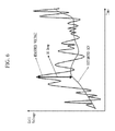
- FIG. 6 is a graph showing that a battery voltage directly measured while a charging/discharging test is performed is different from an open circuit voltage estimated according to the present invention due to the IR drop effect;
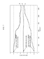
- FIG. 7 is a graph showing that a weighted mean value calculated according to the present invention is converged to an actual resistance regardless of initial conditions as time goes;
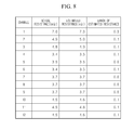
- FIG. 8 is a table showing an actual resistance, an estimated resistance and an error of the estimated resistance in comparison to the actual resistance for each of twelve batteries selected for experiments.
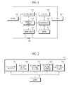
- FIG. 1 is a schematic view showing an apparatus for estimating resistance characteristics of a battery based on a battery voltage variation pattern according to an embodiment of the present invention.
- the apparatus for estimating resistance characteristics of a battery based on a battery voltage variation pattern is connected between a battery 100 and a load 107 , and includes a voltage sensor 101 , a temperature sensor 102 , a current sensor 103 , a memory 104 and a microcontroller 105 .
- the voltage sensor 101 measures a battery voltage under the control of the microcontroller 105 at each resistance characteristic estimation and outputs the battery voltage to the microcontroller 105 .
- the measured battery voltage is different from an actual voltage of the battery due to the IR drop effect.
- the temperature sensor 102 measures a battery temperature under the control of the microcontroller 105 at each resistance characteristic estimation and outputs the battery temperature to the microcontroller 105 .
- the current sensor 103 measures a battery current flowing through a current sensing resistance 108 under the control of the microcontroller 105 at each resistance characteristic estimation and outputs the battery current to the microcontroller 105 .
- the memory 104 stores programs required for estimating resistance characteristics of a battery, various data needed in advance for estimating battery resistance and resistance degradation by using the battery resistance characteristic estimating program, battery voltage, temperature and current data measured by the voltage sensor 101 , the temperature sensor 102 and the current sensor 103 , and various calculation values occurring while the battery resistance characteristic estimating program estimates battery resistance and resistance degradation.
- the microcontroller 105 receives battery voltage, temperature and current data from the voltage sensor 101 , the temperature sensor 102 and the current sensor 103 at each estimation of resistance characteristics of the battery 100 and stores the data in the memory 104 . Also, the microcontroller 105 reads and executes the battery resistance characteristic estimating program from the memory 104 , estimates battery resistance and resistance degradation of a battery and stores the estimated data in the memory 104 , and outputs the estimated battery resistance and resistance degradation through a display 106 as necessary.
- the kind of the battery 100 is not specially limited, and it may adopt lithium ion batteries, lithium polymer batteries, nickel cadmium batteries, nickel hydrogen batteries, nickel zinc batteries and so on, which are rechargeable and whose charging state should be considered.
- the kind of the load 107 is not specially limited, and it may be portable electronic devices such as video cameras, mobile phones, portable PC (Personal Computer), PMP (Portable Multimedia Player) and MP3 players, motors of electric vehicles or hybrid vehicles, DC to DC converters, and so on.
- portable electronic devices such as video cameras, mobile phones, portable PC (Personal Computer), PMP (Portable Multimedia Player) and MP3 players, motors of electric vehicles or hybrid vehicles, DC to DC converters, and so on.
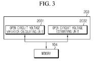
- FIG. 2 is a block diagram showing a battery resistance characteristic estimating program according to an embodiment of the present invention.
- the battery resistance characteristic estimating program 200 is executed by the microcontroller 105 and includes a data storing manager 201 , an open circuit voltage calculator 202 , a weighted mean resistance calculator 203 , a weighted mean resistance convergence calculator 204 and a resistance characteristic estimator 205 .
- the data storing manager 201 receives voltage V n , temperature T n and current I n of the battery from the voltage sensor 101 , the temperature sensor 102 and the current sensor 103 , shown in FIG. 1 , at each resistance characteristic estimation and stores the data in the memory 104 .
- n is the number of measurement times of voltage, temperature and current, and it is identical to the number of resistance characteristic estimation times.
- the open circuit voltage calculator 202 calculates an open circuit voltage variation ⁇ OCV n of a battery using a battery voltage variation pattern, corrects the calculated battery open circuit voltage variation by applying a correction factor according to temperature thereto, and calculates a battery open circuit voltage OCV n at a present stage by reflecting the corrected battery open circuit voltage variation on a previously calculated open circuit voltage OCV n ⁇ 1 .
- the process of calculating the open circuit voltage variation ⁇ OCV n and the process of correcting the open circuit voltage variation ⁇ OCV n according to temperature will be explained in detail later.
- the open circuit voltage calculator 202 stores the calculated ⁇ OCV n in the memory 104 .
- the weighted mean resistance calculator 203 calculates a weighted mean resistance R mean n using the following Math FIG. 1 .
- R mean n ( R n ⁇ 1 ⁇ weight+ R n ) ⁇ (weight+1)
- R n ⁇ 1
- R n
- R n and R n ⁇ 1 are battery resistance parameters respectively calculated at n th time and n ⁇ 1 th time
- V n and V n ⁇ 1 are battery voltages respectively measured at n th time and n ⁇ 1 th time
- OCV n and OCV n ⁇ 1 are open circuit voltages of a battery, respectively calculated at n th time and n ⁇ 1 th time,
- I n and I n ⁇ 1 are battery currents respectively measured at n th time and n ⁇ 1 th time
- n is an integer of 2 or more
- weight is a sufficiently great value, for example 5000 or more.
- FIG. 6 is a graph showing V n periodically measured while charging/discharging a battery in a predetermined pattern and OCV n periodically estimated using the battery voltage variation pattern.
- the measured battery voltage V n is varied more abruptly in comparison to the estimated OCV n . It is caused by the IR drop effect occurring at measuring a battery voltage, so the absolute difference between the measured voltage V n and the estimated voltage OCV n is corresponding to a value obtained by multiplying a battery current I n by a battery resistance R n .
- the battery resistance parameter R n can be considered as representing a resistance characteristic of a battery at the time of measuring V n .
- FIG. 7 is a graph showing a variation pattern of weighted mean resistances R mean 1 , R mean 2 , R mean 3 , R mean 4 , R mean 5 . . . , which are periodically calculated according to time passage based on different conditions of the resistance parameter R 1 , while performing a charging/discharging test to a battery whose resistance is already known.
- a graph A represents a case that the resistance parameter R 1 is set as an actual resistance
- a graph B represents a case that the resistance parameter R 1 is set higher than an actual resistance
- a graph C represents a case that the resistance parameter R 1 is set lower than an actual resistance.
- the weighted mean resistance is converged to an actual resistance value as time goes.
- a convergence of the weighted mean resistance may be used as a parameter for estimating a battery resistance.
- the convergence of weighted mean resistance can be obtained through a long-term charging/discharging experiment.
- a weighted mean resistance is obtained at a specific time point, it is impossible which value the weighted mean resistance would be converged to.
- a convergence of the weighted mean resistance is estimated using a weighted mean sequence in which the obtained weighted mean resistance is an initial condition.
- the weighted mean resistance convergence calculator 204 calculates a weighted mean resistance according to a weighted mean sequence using the weighted mean resistance R mean n , calculated by the weighted mean resistance calculator 203 , as an initial condition by using the following Math FIG. 2 , and this calculation is repeated sufficiently many times. In this way, the weighted mean resistance convergence calculator 204 obtains a convergence R mean n of the weighted mean resistance and stores it in the memory 104 .
- R mean n means a converged value of R mean n .
- k is an integer of 1 or more.
- the weighted mean sequence is calculated as much as a large number over several thousands.
- An initial convergence R mean 1 of the weighted mean resistance may refer to a value that is set at the time of production of the battery and stored in the memory 104 .
- the weighted mean resistance R mean n tends to be converged to an actual resistance value without depending on an initial condition R 1 of the resistance parameter, as shown in FIG. 7 .
- the initial value R mean n 0 is preferably set as a convergence value R mean n ⁇ 1 obtained in a previous stage or an n battery resistance value when the battery was produced. In this case, the number of sequence calculations may be reduced until the weighted mean resistance is converged to an actual resistance value, so the weighted mean resistance may be rapidly converged to an actual resistance value.
- the resistance characteristic estimator 205 reads the weighted mean resistance convergence value R mean n from the memory 104 , and then the resistance characteristic estimator 205 estimates a battery resistance ⁇ tilde over (R) ⁇ n and then stores it in the memory 104 .
- ⁇ tilde over (R) ⁇ n means a battery resistance estimated at an n th resistance estimating.
- the resistance characteristic estimator 205 may estimate the weighted mean resistance convergence value R mean n into the battery resistance ⁇ tilde over (R) ⁇ n as it is.
- the resistance characteristic estimator 205 may estimate a battery resistance ⁇ tilde over (R) ⁇ n corresponding to the weighted mean resistance convergence value R mean n using correlation between the weighted mean resistance convergence value and the battery resistance.
- This correlation may be a look-up table defining battery resistance for each weighted mean resistance convergence value.
- the correlation may be a function using a weighted mean resistance convergence value and a battery resistance as an input parameter and an output parameter, respectively.
- the correlation is obtained through charging/discharging tests for a battery.
- weighted mean resistance convergence values are obtained while charging/discharging experiments are conducted under the same conditions for a long time to a sufficiently large amount of batteries whose actual resistance are already known in a wide range.
- battery resistances corresponding to the weighted mean resistance convergence values obtained through the experiments are configured into a look-up table.
- a functional relation between weighted mean resistance convergence values and battery resistances may be obtained through a numerical analysis using the weighted mean resistance convergence values obtained through the experiments and the battery resistances as input parameters and output parameters, respectively.
- the resistance characteristic estimator 205 may estimate a battery resistance ⁇ tilde over (R) ⁇ n by relatively comparing the weighted mean resistance convergence value R mean n calculated by the weighted mean resistance convergence calculator 204 with the weighted mean resistance convergence value corresponding to an initial resistance value when the battery was produced, stored in the memory 104 .
- the resistance characteristic estimator 205 may calculate a relative ratio of the estimated battery resistance ⁇ tilde over (R) ⁇ n to an initial battery resistance value R initial according to the following Math FIG. 3 after estimating a battery resistance ⁇ tilde over (R) ⁇ n , and then store the calculated result in the memory 104 as SOH R n that is a parameter representing resistance degradation of the battery.
- R initial an initial battery resistance value when the battery was produced
- R limit an allowable maximum resistance available for a battery.
- SOH R n represents a present battery resistance as a relative ratio to an initial battery resistance value.
- the battery resistance tends to increasing as time goes, so SOH R n becomes a parameter to determine how much battery life remains after the battery was initially used.
- SOH R n may be utilized to control a charging/discharging capacity of a battery. For example, if SOH R n is decreased, a charging capacity and a discharging capacity of a battery may be decreased accordingly. In this case, it is possible to effectively prevent a battery from being overcharged or overdischarged by charging or discharging the battery suitably for its resistance.
- the resistance characteristic estimator 205 may output the estimated SOH R n to the display 106 .
- the display 106 is coupled to the microcontroller 105 through an interface.
- the resistance characteristic estimator 205 outputs SOH R n to the display 106 through the interface. Then, the display 106 visually displays SOH R n such that a user may recognize it. SOH R n may be displayed as texts directly or as graphs.
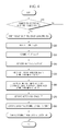
- FIG. 3 is a block diagram showing an open circuit voltage calculator 202 for estimating a battery open circuit voltage using a battery voltage variation pattern according to the present invention in more detail.
- the open circuit voltage calculator 203 includes an open circuit voltage variation calculating unit 2031 and an open circuit voltage estimating unit 2032 .
- the open circuit voltage variation calculating unit 2031 calculates an open circuit voltage variation based on an open circuit voltage at a last stage using a battery voltage variation pattern in order to calculate a present battery open circuit voltage. In other words, the open circuit voltage variation calculating unit 2031 calculates how much a battery open circuit voltage at a present stage is changed based on the open circuit voltage at a last stage.
- the open circuit voltage variation calculating unit 2031 reads a battery voltage V n measured at a present resistance characteristic estimation, a battery voltage V n ⁇ 1 measured at a last resistance characteristic estimation and a battery temperature T n measured at a present resistance characteristic estimation from the memory 104 . After that, the open circuit voltage variation calculating unit 2031 calculates an open circuit voltage variation ⁇ OCV n according to the following Math FIG. 4 .
- G(V) is an open circuit voltage variation operation function for mapping a battery voltage variation ‘V n ⁇ V n ⁇ 1 ’, into an open circuit voltage variation ⁇ OCV n
- F(T) is an open circuit voltage correction function for correcting the open circuit voltage variation ⁇ OCV n by reflecting an open circuit voltage change according to temperature.
- G(V) is a function not for converting a battery voltage variation into an open circuit voltage variation as it is, but for converting the battery voltage variation into the open circuit voltage variation by correcting an error of battery voltage caused by IR drop (namely, a difference between a measured voltage and an actual voltage).
- G(V) decreases the battery voltage variation and then outputs the decreased battery voltage variation as a battery open circuit voltage variation.
- G(V) outputs the battery voltage variation as a battery open circuit voltage variation as it is.
- G(V) amplifies the battery voltage variation slightly and then outputs the slightly amplified battery voltage variation as a battery open circuit voltage variation.
- G(V) may be obtained by mathematically modeling a correlation between a battery voltage variation pattern and an open circuit voltage variation corresponding thereto under a certain temperature condition.
- the mathematical modeling function may be obtained by analyzing a correlation existing between a variation pattern of battery voltages V n , V n ⁇ 1 and V n ⁇ 2 and an open circuit voltage variation ⁇ OCV n corresponding thereto under a laboratory condition allowing measurement of battery voltage and battery open circuit voltage.
- the number of battery voltages configuring a variation pattern of battery voltages may be extended to four or more.
- G(V) may be generalized as in the following Math FIG. 5 .
- g(V n , V n ⁇ 1 , V n ⁇ 2 . . . ) is a pattern function defining a variation pattern of battery voltages measured at each resistance characteristic estimation.
- the symbol ‘. . . ’ means that the pattern function may be defined using at least three battery voltages, including a battery voltage measured at a present stage.
- the pattern function is defined by analyzing a correlation between a plurality of battery voltage variations and battery open circuit voltage variations, experimentally obtained.
- the function g may be defined as a relative ratio of a voltage variation at a last stage to a voltage variation at a present stage.
- the present invention is not limited to any specific math figure of the pattern function g.
- F(T) corrects the open circuit voltage variation, calculated by G(V), according to a temperature condition.
- F(T) is a function for correcting an open circuit voltage variation calculated by G(V) in case a battery temperature is different from a standard temperature set as a calculation condition of G(V).
- F(T) may be obtained by analyzing a correlation between a battery voltage variation pattern and a battery open circuit voltage variation while changing temperature at regular intervals. In other words, under the experimental conditions that a battery voltage variation pattern at each measurement temperature set as regular intervals, for example 1° C.
- F(T) may be obtained by measuring a changing amount of a battery open circuit voltage variation ⁇ OCV n in comparison to ⁇ OCV n obtained at a standard temperature and then applying a mathematical modeling for the temperature and the changing amount of ⁇ OCV n by using the temperature T and the changing amount ⁇ OCV n as an input parameter and an output parameter, respectively.
- the obtained F(T) becomes a function outputting a correction factor of a battery open circuit voltage variation using the battery temperature T as an input parameter.
- a look-up table with correction factors depending on each T value and stores the look-up table in the memory 104 such that a correction factor for each temperature, stored in the look-up table, may be referred to for obtaining a correction factor used to correct a battery open circuit voltage variation.
- the open circuit voltage estimating unit 2032 reads an open circuit voltage OCV n ⁇ 1 calculated at a last resistance characteristic estimation from the memory 104 , and then adds the open circuit voltage variation ⁇ OCV n calculated by the open circuit voltage variation calculating unit 2031 to OCV n ⁇ 1 to calculate an open circuit voltage OCV n and stores it in the memory 104 .
- the open circuit voltage estimating unit 2032 calculates a weighted mean value V n (meanvalue) between a battery voltage V n and a battery voltage measured at a previous stage through the following Math FIG. 6 .
- a k is decreased as k increases.
- a k may have a value starting from 100 and decreased by 1.
- a 1 *V 1 +A 2 *V 2 + . . . +A k ⁇ 2 *V k ⁇ 2 (3 ⁇ k ⁇ n) may be omitted. Even in this case, the changing tendency of A k is maintained as above.
- a 1 *V 1 +A 2 *V 2 + . . . +A n ⁇ 2 *V n ⁇ 2 is set as 0 and a larger value is endowed to A n ⁇ 1 rather than A n .
- 90 and 10 may be endowed to A n ⁇ 1 and A n , respectively.
- the open circuit voltage estimating unit 2032 may correct the open circuit voltage once again by adding a difference between the calculated weighted mean value V n (meanvalue) and the open circuit voltage OCV n ⁇ 1 to the calculated open circuit voltage OCV n for additional correction. If the weighted mean value V n (meanvalue) is calculated and used for correcting an open circuit voltage additionally, a calculation error of the open circuit voltage may be decreased though a voltage output from the battery 100 is abnormally changed. If the open circuit voltage is completely corrected using the weighted mean value V n (meanvalue) , the open circuit voltage estimating unit 2032 stores the corrected open circuit voltage OCV n in the memory 104 .
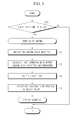
- FIG. 4 is a flowchart illustrating a method for estimating battery resistance characteristics based on a battery voltage variation pattern according to the present invention.
- each step is executed by the microcontroller 105 shown in FIG. 1 .
- step S 10 it is determined whether there is a request for resistance characteristic estimation of a battery.
- the resistance characteristic estimation request may be input from the outside or automatically generated by a battery resistance characteristic estimating program.
- step S 20 a battery resistance parameter R n ⁇ 1 and a weighted mean resistance convergence value R mean n ⁇ 1 , obtained at a last resistance characteristic estimation are read from the memory. Subsequently, in the step S 30 , V n , T n and I n are measured using the voltage sensor, the temperature sensor and the current sensor.
- a battery open circuit voltage OCV n is estimated by means of a battery voltage variation pattern, and a battery resistance parameter R n is calculated from V n , I n and OCV n .
- an initial condition R mean n 1 of the weighted mean sequence is obtained from R n ⁇ 1 and R n .
- the Math FIG. 2 is used when calculating R mean n 1 .
- the weighted mean sequence is repeatedly calculated as much as a sufficient number using the initial conditions R mean n 1 and R mean n ⁇ 1 to calculate a convergence value R mean n of the weighted mean resistance.
- the Math FIG. 2 is used when calculating R mean n .
- R mean n ⁇ 1 may be substituted with a preset R mean 1 .
- R mean 1 may be set with an initial battery resistance value when the battery was initially produced.
- a battery resistance ⁇ tilde over (R) ⁇ n is estimated from the convergence value R mean n of the weighted mean resistance.
- the battery resistance ⁇ tilde over (R) ⁇ n may be estimated to be identical to the convergence value R mean n of the weighted mean resistance.
- a battery resistance ⁇ tilde over (R) ⁇ n corresponding to the convergence value R mean n of the weighted mean resistance may be estimated using the correlation between the convergence value of the weighted mean resistance and the battery resistance.
- the correlation may be a look-up table defining battery resistance for each convergence value of the weighted mean resistance or a function using the convergence value of the weighted mean resistance and the battery resistance as an input parameter and an output parameter, respectively.
- a battery resistance may be estimated based on an initial battery resistance value by relatively comparing the convergence value of the weighted mean resistance corresponding to the initial battery resistance value with the weighted mean convergence value R mean n calculated in the step S 60 . In other words, the initial battery resistance value is increased as much as an increment ratio of the weighted mean convergence value, and the increased value may be estimated as a battery resistance.
- step S 80 a relatively increment of the estimated battery resistance ⁇ tilde over (R) ⁇ n is calculated based on the initial battery resistance value R initial , and SOH R n is estimated by means of the calculated relative increment ratio.
- the estimated SOH R n is stored in the memory 104 or output to the display 106 .
- the relative increment ratio is preferably calculated based on an allowable maximum resistance R limit according to the Math FIG. 3 .
- FIG. 5 is a flowchart illustrating a process for estimating an open circuit voltage OCV n based on a battery voltage variation pattern in the step S 40 of FIG. 4 .
- each step is executed by the microcontroller 105 shown in FIG. 1 .
- step P 10 it is determined whether there is a request for estimation of an open circuit voltage OCV n .
- the request for estimation may be input from the outside or automatically generated according to a program algorithm.
- step P 10 If there is a request for estimation of OCV n in the step P 10 , an open circuit voltage estimating step is executed. If there is no request for estimation of OCV n , the process is terminated.
- a battery voltage variation pattern stored in the memory is read.
- the battery voltage variation pattern includes at least V n , V n ⁇ 1 and V n ⁇ 2 .
- an open circuit voltage variation ⁇ OCV n is calculated by means of the battery voltage variation pattern and a battery temperature.
- the calculation method for an open circuit voltage variation ⁇ OCV n is already explained above.
- V 1 and V 2 as well as OCV 1 and OCV 2 are initialized into battery voltages in an unloaded state, measured right before a battery is connected to a load.
- V 1 and V 2 as well as OCV 1 and OCV 2 are set as battery voltages measured when the vehicle starts using a key.
- the open circuit voltage variation ⁇ OCV n is added to a last open circuit voltage OCV n ⁇ 1 to calculate a present open circuit voltage OCV n .
- a weighted mean value of a present battery voltage V n and a last battery voltage V n ⁇ 1 is calculated, and a difference between the calculated weighted mean value and the last open circuit voltage OCV n ⁇ 1 is added to the present open circuit voltage OCV n to additionally correct the open circuit voltage OCV n .
- the calculation method for weight mean value is already explained above.
- the estimated open circuit voltage OCV n is stored in the memory 104 .
- FIG. 8 is a table showing an actual resistance, an estimated resistance and an error of the estimated resistance in comparison to the actual resistance for each of twelve batteries selected for experiments.
- the battery resistance estimated according to the present invention is within the range of 3% in comparison to an actual resistance.
- the present invention ensures estimation of battery resistance with high accuracy, and also enables to accurately estimate battery resistance degradation that is a parameter capable of being calculated from the battery resistance.
- battery resistance characteristics may be accurately estimated by simple sequence calculation.
- the accurately estimated battery resistance may be applied in various ways, for example to estimate a time for exchange of a battery.
- the present invention may prevent overcharging or overdischarging, thereby improving safety of a battery.
Landscapes
- Physics & Mathematics (AREA)
- General Physics & Mathematics (AREA)
- Secondary Cells (AREA)
- Measurement Of Resistance Or Impedance (AREA)
Abstract
Description
R mean n=(R n−1×weight+R n)÷(weight+1)
R n−1=|V n−1 −OCV n−1|÷|I n−1|
R n=|V n−1 −OCV n|÷|I n|
R mean n k+1=(R mean n k−1×weight+R mean n k)/(weight+1)
R mean n 1=(R n−1×weight+R n)÷(weight+1)
SOH R n=[(R limit −{tilde over (R)} n)÷(R limit −R initial)]×100
ΔOCV n =OCV n −OCV n−1 =G(V)×F(T)
G(V)=(V n −V n−1)×g(V n , V n−1 , V n−2 . . . )
V n (meanvalue)=(A 1 *V 1 +A 2 *V 2 + . . . +A n−1 *V n−1 +A n *V n)/A total
A total =A 1 +A 2 +A 3 + . . . +A n
Claims (31)
R mean n=(R n−1×weight+R n)÷(weight+1)
R n−1 =|V n−1 −OCV n−1|÷|I n−1|
R n =|V n −OCV n|÷|I n|
R mean n k+1=(R mean n k−1×weight+R mean n k)/(weight+1),
R mean n 1=(R n−1×weight+R n)÷(weight+1),
R mean n=(R n−1×weight+R n)÷(weight+1)
R n−1 =|V n−1 −OCV n−1|÷|I n−1|
R n =|V n −OCV n|÷|I n|
R mean n k+1=(R mean n k−1×weight+R mean n k)/(weight+1),
R mean n 1=(R n−1×weight+R n)÷(weight+1),
Priority Applications (1)
| Application Number | Priority Date | Filing Date | Title |
|---|---|---|---|
| US13/172,922 US8185332B2 (en) | 2008-08-14 | 2011-06-30 | Apparatus and method for estimating resistance characteristics of battery based on open circuit voltage estimated by battery voltage variation pattern |
Applications Claiming Priority (4)
| Application Number | Priority Date | Filing Date | Title |
|---|---|---|---|
| KR10-2008-0080122 | 2008-08-14 | ||
| KR1020080080122A KR100927541B1 (en) | 2008-08-14 | 2008-08-14 | Apparatus and method for estimating battery resistance characteristics using battery voltage behavior |
| US12/484,434 US7996167B2 (en) | 2008-08-14 | 2009-06-15 | Apparatus and method for estimating resistance characteristics of battery based on open circuit voltage estimated by battery voltage variation pattern |
| US13/172,922 US8185332B2 (en) | 2008-08-14 | 2011-06-30 | Apparatus and method for estimating resistance characteristics of battery based on open circuit voltage estimated by battery voltage variation pattern |
Related Parent Applications (1)
| Application Number | Title | Priority Date | Filing Date |
|---|---|---|---|
| US12/484,434 Continuation US7996167B2 (en) | 2008-08-14 | 2009-06-15 | Apparatus and method for estimating resistance characteristics of battery based on open circuit voltage estimated by battery voltage variation pattern |
Publications (2)
| Publication Number | Publication Date |
|---|---|
| US20110256434A1 US20110256434A1 (en) | 2011-10-20 |
| US8185332B2 true US8185332B2 (en) | 2012-05-22 |
Family
ID=41605200
Family Applications (2)
| Application Number | Title | Priority Date | Filing Date |
|---|---|---|---|
| US12/484,434 Active 2030-02-04 US7996167B2 (en) | 2008-08-14 | 2009-06-15 | Apparatus and method for estimating resistance characteristics of battery based on open circuit voltage estimated by battery voltage variation pattern |
| US13/172,922 Active US8185332B2 (en) | 2008-08-14 | 2011-06-30 | Apparatus and method for estimating resistance characteristics of battery based on open circuit voltage estimated by battery voltage variation pattern |
Family Applications Before (1)
| Application Number | Title | Priority Date | Filing Date |
|---|---|---|---|
| US12/484,434 Active 2030-02-04 US7996167B2 (en) | 2008-08-14 | 2009-06-15 | Apparatus and method for estimating resistance characteristics of battery based on open circuit voltage estimated by battery voltage variation pattern |
Country Status (8)
| Country | Link |
|---|---|
| US (2) | US7996167B2 (en) |
| EP (1) | EP2325658B1 (en) |
| JP (1) | JP5661625B2 (en) |
| KR (1) | KR100927541B1 (en) |
| CN (1) | CN102124354B (en) |
| BR (1) | BRPI0912595B1 (en) |
| TW (1) | TWI384246B (en) |
| WO (1) | WO2010018919A1 (en) |
Cited By (2)
| Publication number | Priority date | Publication date | Assignee | Title |
|---|---|---|---|---|
| US20190195942A1 (en) * | 2017-12-21 | 2019-06-27 | Lg Chem, Ltd. | Apparatus And Method For Diagnosing Current Sensor |
| EP4571337A1 (en) * | 2023-12-11 | 2025-06-18 | Samsung SDI Co., Ltd. | Apparatus and method for calculating battery energy |
Families Citing this family (31)
| Publication number | Priority date | Publication date | Assignee | Title |
|---|---|---|---|---|
| KR100927541B1 (en) * | 2008-08-14 | 2009-11-17 | 주식회사 엘지화학 | Apparatus and method for estimating battery resistance characteristics using battery voltage behavior |
| US8688303B2 (en) * | 2010-02-26 | 2014-04-01 | Segway, Inc. | Apparatus and methods for control of a vehicle |
| FR2968769B1 (en) * | 2010-12-10 | 2012-12-14 | Peugeot Citroen Automobiles Sa | METHOD FOR DETERMINING THE HEALTH CONDITION OF A BATTERY FOR POWERING AN ELECTRIC VEHICLE |
| US8449998B2 (en) * | 2011-04-25 | 2013-05-28 | Lg Chem, Ltd. | Battery system and method for increasing an operational life of a battery cell |
| CN103197115A (en) * | 2012-01-05 | 2013-07-10 | 新普科技股份有限公司 | Voltage Correction Method for Rechargeable Battery Pack |
| US8937838B2 (en) * | 2012-01-10 | 2015-01-20 | Sk Hynix Memory Solutions Inc. | Finding optimal read thresholds and related voltages for solid state memory |
| EP3136118B1 (en) * | 2012-06-13 | 2018-01-31 | LG Chem, Ltd. | Apparatus and method for estimating voltage of secondary battery including blended cathode material |
| US20140019789A1 (en) * | 2012-07-10 | 2014-01-16 | Apple Inc. | Monitoring a battery in an electronic device |
| EP2915161B1 (en) * | 2012-11-05 | 2020-08-19 | University of Florida Research Foundation, Inc. | Brightness compensation in a display |
| KR101983392B1 (en) * | 2012-11-27 | 2019-05-29 | 에스케이이노베이션 주식회사 | Apparatus and Method for estimating the battery SOC |
| WO2015104505A1 (en) * | 2014-01-08 | 2015-07-16 | Electricite De France | Electrical measuring device for measuring the resistance of an earth connection of an electrical facility |
| CN105866551B (en) * | 2016-06-27 | 2018-11-27 | 上海电气钠硫储能技术有限公司 | A kind of sodium-sulphur battery internal resistance detection method |
| KR102579538B1 (en) * | 2016-10-05 | 2023-09-18 | 삼성전자주식회사 | Method and apparatus for controlling battery charging |
| KR102182691B1 (en) * | 2017-10-20 | 2020-11-24 | 주식회사 엘지화학 | Apparatus and method for estimating resistance of battery |
| KR102296993B1 (en) | 2017-11-17 | 2021-09-01 | 주식회사 엘지에너지솔루션 | Apparatus and Method for Estimating Resistance of Secondary Battery |
| KR102416548B1 (en) * | 2018-02-01 | 2022-07-01 | 주식회사 엘지에너지솔루션 | Method and battery management system for estimating parameters of battery equivalent circuit model for a battery |
| EP3775948B1 (en) | 2018-04-06 | 2024-05-22 | Volvo Truck Corporation | Method and system for estimating battery properties in a vehicle drive system |
| CN112384814A (en) * | 2018-07-10 | 2021-02-19 | 住友电气工业株式会社 | Secondary battery parameter estimation device, secondary battery parameter estimation method, and program |
| CN112909362B (en) * | 2018-10-16 | 2022-06-10 | 宁德时代新能源科技股份有限公司 | Cell voltage correction method, device, equipment and medium |
| KR102521577B1 (en) * | 2019-03-18 | 2023-04-12 | 주식회사 엘지에너지솔루션 | Apparatus for estimating state of battery |
| KR102520673B1 (en) | 2019-03-18 | 2023-04-10 | 주식회사 엘지에너지솔루션 | Apparatus for estimating state of battery |
| KR102493232B1 (en) | 2019-03-18 | 2023-01-27 | 주식회사 엘지에너지솔루션 | Apparatus for managing battery |
| KR102521576B1 (en) * | 2019-03-18 | 2023-04-12 | 주식회사 엘지에너지솔루션 | Apparatus for managing battery |
| CN112630538B (en) | 2019-09-24 | 2024-04-16 | 台达电子工业股份有限公司 | Estimation method of brake resistance |
| ES3042958T3 (en) * | 2020-10-22 | 2025-11-24 | Lg Energy Solution Ltd | Battery apparatus and method for estimating resistance state |
| KR20220139755A (en) * | 2021-04-08 | 2022-10-17 | 주식회사 엘지에너지솔루션 | Apparatus and method for diagnosing battery |
| CN115248379B (en) * | 2021-04-26 | 2025-04-11 | 广汽埃安新能源汽车股份有限公司 | A power battery micro-short circuit diagnosis method and system based on multi-scenario fusion |
| US20250138102A1 (en) * | 2022-09-21 | 2025-05-01 | Lg Energy Solution, Ltd. | Apparatus and Method for Diagnosing State of Battery |
| CN115327419B (en) * | 2022-10-18 | 2023-04-28 | 长兴太湖能谷科技有限公司 | Online identification method for internal resistance parameters of storage battery |
| KR102698009B1 (en) * | 2022-10-26 | 2024-08-21 | 주식회사 엘지에너지솔루션 | Apparatus and method for diagnosing battery |
| CN116930765B (en) * | 2023-07-05 | 2025-05-23 | 中创新航科技集团股份有限公司 | Prediction method and prediction device for open-circuit voltage of battery and battery pack |
Citations (7)
| Publication number | Priority date | Publication date | Assignee | Title |
|---|---|---|---|---|
| JP2002189066A (en) | 2000-12-22 | 2002-07-05 | Hitachi Ltd | Battery level estimation method |
| US6832171B2 (en) | 2002-12-29 | 2004-12-14 | Texas Instruments Incorporated | Circuit and method for determining battery impedance increase with aging |
| US20060176022A1 (en) | 2005-02-07 | 2006-08-10 | Fuji Jukogyo Kabushiki Kaisha | Battery management apparatus |
| JP2007024673A (en) | 2005-07-15 | 2007-02-01 | Furukawa Electric Co Ltd:The | Method and device for detecting state-of-charge of storage battery |
| US7612532B2 (en) * | 2005-06-21 | 2009-11-03 | Gm Global Technology Operations, Inc. | Method for controlling and monitoring using a state estimator having variable forgetting factors |
| US20100036626A1 (en) | 2008-08-08 | 2010-02-11 | Kang Jung-Soo | Apparatus and method for estimating state of health of battery based on battery voltage variation pattern |
| US7996167B2 (en) * | 2008-08-14 | 2011-08-09 | Lg Chem, Ltd. | Apparatus and method for estimating resistance characteristics of battery based on open circuit voltage estimated by battery voltage variation pattern |
Family Cites Families (7)
| Publication number | Priority date | Publication date | Assignee | Title |
|---|---|---|---|---|
| JP3540437B2 (en) * | 1995-06-05 | 2004-07-07 | 本田技研工業株式会社 | Battery status determination device |
| DE10106508A1 (en) * | 2001-02-13 | 2002-08-29 | Bosch Gmbh Robert | Method and arrangement for determining the performance of a battery |
| JP4682509B2 (en) * | 2003-11-26 | 2011-05-11 | 日産自動車株式会社 | Battery open voltage calculation method and charge amount calculation method |
| TWI267647B (en) * | 2004-08-19 | 2006-12-01 | Nat Huwei Institue Of Technolo | Battery aging level measurement device and method |
| JP4690223B2 (en) * | 2006-02-24 | 2011-06-01 | 株式会社デンソー | Battery state quantity calculation device |
| US7521895B2 (en) * | 2006-03-02 | 2009-04-21 | Lg Chem, Ltd. | System and method for determining both an estimated battery state vector and an estimated battery parameter vector |
| KR100804698B1 (en) * | 2006-06-26 | 2008-02-18 | 삼성에스디아이 주식회사 | The method of assuming the state of charge of the battery, battery management system using the method and the driving method of the battery management system using the method |
-
2008
- 2008-08-14 KR KR1020080080122A patent/KR100927541B1/en active Active
-
2009
- 2009-05-19 JP JP2011522891A patent/JP5661625B2/en active Active
- 2009-05-19 CN CN2009801317800A patent/CN102124354B/en active Active
- 2009-05-19 BR BRPI0912595A patent/BRPI0912595B1/en active IP Right Grant
- 2009-05-19 WO PCT/KR2009/002629 patent/WO2010018919A1/en not_active Ceased
- 2009-05-19 EP EP09806781.2A patent/EP2325658B1/en active Active
- 2009-06-15 TW TW098119902A patent/TWI384246B/en active
- 2009-06-15 US US12/484,434 patent/US7996167B2/en active Active
-
2011
- 2011-06-30 US US13/172,922 patent/US8185332B2/en active Active
Patent Citations (8)
| Publication number | Priority date | Publication date | Assignee | Title |
|---|---|---|---|---|
| JP2002189066A (en) | 2000-12-22 | 2002-07-05 | Hitachi Ltd | Battery level estimation method |
| US6832171B2 (en) | 2002-12-29 | 2004-12-14 | Texas Instruments Incorporated | Circuit and method for determining battery impedance increase with aging |
| US20060176022A1 (en) | 2005-02-07 | 2006-08-10 | Fuji Jukogyo Kabushiki Kaisha | Battery management apparatus |
| JP2006215001A (en) | 2005-02-07 | 2006-08-17 | Fuji Heavy Ind Ltd | Battery management device |
| US7612532B2 (en) * | 2005-06-21 | 2009-11-03 | Gm Global Technology Operations, Inc. | Method for controlling and monitoring using a state estimator having variable forgetting factors |
| JP2007024673A (en) | 2005-07-15 | 2007-02-01 | Furukawa Electric Co Ltd:The | Method and device for detecting state-of-charge of storage battery |
| US20100036626A1 (en) | 2008-08-08 | 2010-02-11 | Kang Jung-Soo | Apparatus and method for estimating state of health of battery based on battery voltage variation pattern |
| US7996167B2 (en) * | 2008-08-14 | 2011-08-09 | Lg Chem, Ltd. | Apparatus and method for estimating resistance characteristics of battery based on open circuit voltage estimated by battery voltage variation pattern |
Cited By (3)
| Publication number | Priority date | Publication date | Assignee | Title |
|---|---|---|---|---|
| US20190195942A1 (en) * | 2017-12-21 | 2019-06-27 | Lg Chem, Ltd. | Apparatus And Method For Diagnosing Current Sensor |
| US10545185B2 (en) * | 2017-12-21 | 2020-01-28 | Lg Chem, Ltd. | Apparatus and method for diagnosing current sensor |
| EP4571337A1 (en) * | 2023-12-11 | 2025-06-18 | Samsung SDI Co., Ltd. | Apparatus and method for calculating battery energy |
Also Published As
| Publication number | Publication date |
|---|---|
| EP2325658A4 (en) | 2013-11-13 |
| BRPI0912595B1 (en) | 2020-02-04 |
| CN102124354B (en) | 2013-09-18 |
| US20100042345A1 (en) | 2010-02-18 |
| JP2011530709A (en) | 2011-12-22 |
| EP2325658B1 (en) | 2015-01-07 |
| US7996167B2 (en) | 2011-08-09 |
| KR100927541B1 (en) | 2009-11-17 |
| WO2010018919A1 (en) | 2010-02-18 |
| JP5661625B2 (en) | 2015-01-28 |
| CN102124354A (en) | 2011-07-13 |
| BRPI0912595A2 (en) | 2015-10-13 |
| EP2325658A1 (en) | 2011-05-25 |
| TWI384246B (en) | 2013-02-01 |
| TW201007191A (en) | 2010-02-16 |
| US20110256434A1 (en) | 2011-10-20 |
Similar Documents
| Publication | Publication Date | Title |
|---|---|---|
| US8185332B2 (en) | Apparatus and method for estimating resistance characteristics of battery based on open circuit voltage estimated by battery voltage variation pattern | |
| US8046181B2 (en) | Apparatus and method for estimating state of health of battery based on battery voltage variation pattern | |
| KR100985667B1 (en) | Battery open circuit voltage estimator, battery charge state estimator and its control method | |
| US9287723B2 (en) | Cell balancing apparatus and method using a voltage variation pattern of each cell to estimate an open circuit voltage value for each cell | |
| KR101846690B1 (en) | System and Method for Managing Battery on the basis of required time for Charging | |
| KR100911317B1 (en) | Battery capacity deterioration estimation apparatus and method using battery voltage behavior | |
| KR101402802B1 (en) | Cell balancing apparatus and method using voltage change behavior of battery cell | |
| US20060212277A1 (en) | Apparatus and method for estimating battery state of charge | |
| JP2023523370A (en) | Method and apparatus for detecting lithium plating and method and apparatus for obtaining polarization ratio | |
| JP2006242880A (en) | Power supply state detection device, power supply device, and initial characteristic extraction device used for power supply device | |
| CN105005000A (en) | System and method for sensing battery capacity | |
| Çadırcı et al. | Microcontroller-based on-line state-of-charge estimator for sealed lead–acid batteries | |
| CN118690704B (en) | Lithium battery equivalent circuit model parameter online adaptive adjustment method and related device | |
| CN112912745B (en) | Method for determining the state of charge and the state of aging of an electrochemical cell | |
| WO2006057469A1 (en) | Method and system for joint battery stateand parameter estimation | |
| KR100911315B1 (en) | Apparatus and method for estimating battery resistance characteristics using battery voltage behavior | |
| KR20150034593A (en) | Method and apparatus for state of charge estimation of battery | |
| CN117932909B (en) | SOC method and SOC system applied to energy storage system | |
| CN119619885A (en) | Battery system SOC calibration method, device, electronic device and storage medium | |
| Pop et al. | A State-of-Charge indication algorithm |
Legal Events
| Date | Code | Title | Description |
|---|---|---|---|
| FEPP | Fee payment procedure |
Free format text: PAYOR NUMBER ASSIGNED (ORIGINAL EVENT CODE: ASPN); ENTITY STATUS OF PATENT OWNER: LARGE ENTITY |
|
| STCF | Information on status: patent grant |
Free format text: PATENTED CASE |
|
| FPAY | Fee payment |
Year of fee payment: 4 |
|
| MAFP | Maintenance fee payment |
Free format text: PAYMENT OF MAINTENANCE FEE, 8TH YEAR, LARGE ENTITY (ORIGINAL EVENT CODE: M1552); ENTITY STATUS OF PATENT OWNER: LARGE ENTITY Year of fee payment: 8 |
|
| AS | Assignment |
Owner name: LG ENERGY SOLUTION, LTD., KOREA, REPUBLIC OF Free format text: ASSIGNMENT OF ASSIGNORS INTEREST;ASSIGNOR:LG CHEM, LTD.;REEL/FRAME:058295/0068 Effective date: 20211027 Owner name: LG ENERGY SOLUTION, LTD., KOREA, REPUBLIC OF Free format text: ASSIGNMENT OF ASSIGNOR'S INTEREST;ASSIGNOR:LG CHEM, LTD.;REEL/FRAME:058295/0068 Effective date: 20211027 |
|
| MAFP | Maintenance fee payment |
Free format text: PAYMENT OF MAINTENANCE FEE, 12TH YEAR, LARGE ENTITY (ORIGINAL EVENT CODE: M1553); ENTITY STATUS OF PATENT OWNER: LARGE ENTITY Year of fee payment: 12 |