EP2325577B1 - Wärmepumpe - Google Patents
Wärmepumpe Download PDFInfo
- Publication number
- EP2325577B1 EP2325577B1 EP10251357.9A EP10251357A EP2325577B1 EP 2325577 B1 EP2325577 B1 EP 2325577B1 EP 10251357 A EP10251357 A EP 10251357A EP 2325577 B1 EP2325577 B1 EP 2325577B1
- Authority
- EP
- European Patent Office
- Prior art keywords
- refrigerant
- flow path
- heat exchanger
- injection flow
- condenser
- Prior art date
- Legal status (The legal status is an assumption and is not a legal conclusion. Google has not performed a legal analysis and makes no representation as to the accuracy of the status listed.)
- Not-in-force
Links
Images


Classifications
-
- F—MECHANICAL ENGINEERING; LIGHTING; HEATING; WEAPONS; BLASTING
- F25—REFRIGERATION OR COOLING; COMBINED HEATING AND REFRIGERATION SYSTEMS; HEAT PUMP SYSTEMS; MANUFACTURE OR STORAGE OF ICE; LIQUEFACTION SOLIDIFICATION OF GASES
- F25B—REFRIGERATION MACHINES, PLANTS OR SYSTEMS; COMBINED HEATING AND REFRIGERATION SYSTEMS; HEAT PUMP SYSTEMS
- F25B30/00—Heat pumps
- F25B30/02—Heat pumps of the compression type
-
- F—MECHANICAL ENGINEERING; LIGHTING; HEATING; WEAPONS; BLASTING
- F04—POSITIVE - DISPLACEMENT MACHINES FOR LIQUIDS; PUMPS FOR LIQUIDS OR ELASTIC FLUIDS
- F04C—ROTARY-PISTON, OR OSCILLATING-PISTON, POSITIVE-DISPLACEMENT MACHINES FOR LIQUIDS; ROTARY-PISTON, OR OSCILLATING-PISTON, POSITIVE-DISPLACEMENT PUMPS
- F04C18/00—Rotary-piston pumps specially adapted for elastic fluids
- F04C18/02—Rotary-piston pumps specially adapted for elastic fluids of arcuate-engagement type, i.e. with circular translatory movement of co-operating members, each member having the same number of teeth or tooth-equivalents
-
- F—MECHANICAL ENGINEERING; LIGHTING; HEATING; WEAPONS; BLASTING
- F25—REFRIGERATION OR COOLING; COMBINED HEATING AND REFRIGERATION SYSTEMS; HEAT PUMP SYSTEMS; MANUFACTURE OR STORAGE OF ICE; LIQUEFACTION SOLIDIFICATION OF GASES
- F25B—REFRIGERATION MACHINES, PLANTS OR SYSTEMS; COMBINED HEATING AND REFRIGERATION SYSTEMS; HEAT PUMP SYSTEMS
- F25B1/00—Compression machines, plants or systems with non-reversible cycle
- F25B1/04—Compression machines, plants or systems with non-reversible cycle with compressor of rotary type
-
- F—MECHANICAL ENGINEERING; LIGHTING; HEATING; WEAPONS; BLASTING
- F25—REFRIGERATION OR COOLING; COMBINED HEATING AND REFRIGERATION SYSTEMS; HEAT PUMP SYSTEMS; MANUFACTURE OR STORAGE OF ICE; LIQUEFACTION SOLIDIFICATION OF GASES
- F25B—REFRIGERATION MACHINES, PLANTS OR SYSTEMS; COMBINED HEATING AND REFRIGERATION SYSTEMS; HEAT PUMP SYSTEMS
- F25B1/00—Compression machines, plants or systems with non-reversible cycle
- F25B1/10—Compression machines, plants or systems with non-reversible cycle with multi-stage compression
-
- F—MECHANICAL ENGINEERING; LIGHTING; HEATING; WEAPONS; BLASTING
- F25—REFRIGERATION OR COOLING; COMBINED HEATING AND REFRIGERATION SYSTEMS; HEAT PUMP SYSTEMS; MANUFACTURE OR STORAGE OF ICE; LIQUEFACTION SOLIDIFICATION OF GASES
- F25B—REFRIGERATION MACHINES, PLANTS OR SYSTEMS; COMBINED HEATING AND REFRIGERATION SYSTEMS; HEAT PUMP SYSTEMS
- F25B41/00—Fluid-circulation arrangements
- F25B41/30—Expansion means; Dispositions thereof
- F25B41/385—Dispositions with two or more expansion means arranged in parallel on a refrigerant line leading to the same evaporator
-
- F—MECHANICAL ENGINEERING; LIGHTING; HEATING; WEAPONS; BLASTING
- F25—REFRIGERATION OR COOLING; COMBINED HEATING AND REFRIGERATION SYSTEMS; HEAT PUMP SYSTEMS; MANUFACTURE OR STORAGE OF ICE; LIQUEFACTION SOLIDIFICATION OF GASES
- F25B—REFRIGERATION MACHINES, PLANTS OR SYSTEMS; COMBINED HEATING AND REFRIGERATION SYSTEMS; HEAT PUMP SYSTEMS
- F25B41/00—Fluid-circulation arrangements
- F25B41/30—Expansion means; Dispositions thereof
- F25B41/39—Dispositions with two or more expansion means arranged in series, i.e. multi-stage expansion, on a refrigerant line leading to the same evaporator
-
- F—MECHANICAL ENGINEERING; LIGHTING; HEATING; WEAPONS; BLASTING
- F25—REFRIGERATION OR COOLING; COMBINED HEATING AND REFRIGERATION SYSTEMS; HEAT PUMP SYSTEMS; MANUFACTURE OR STORAGE OF ICE; LIQUEFACTION SOLIDIFICATION OF GASES
- F25B—REFRIGERATION MACHINES, PLANTS OR SYSTEMS; COMBINED HEATING AND REFRIGERATION SYSTEMS; HEAT PUMP SYSTEMS
- F25B49/00—Arrangement or mounting of control or safety devices
- F25B49/02—Arrangement or mounting of control or safety devices for compression type machines, plants or systems
-
- F—MECHANICAL ENGINEERING; LIGHTING; HEATING; WEAPONS; BLASTING
- F25—REFRIGERATION OR COOLING; COMBINED HEATING AND REFRIGERATION SYSTEMS; HEAT PUMP SYSTEMS; MANUFACTURE OR STORAGE OF ICE; LIQUEFACTION SOLIDIFICATION OF GASES
- F25B—REFRIGERATION MACHINES, PLANTS OR SYSTEMS; COMBINED HEATING AND REFRIGERATION SYSTEMS; HEAT PUMP SYSTEMS
- F25B2339/00—Details of evaporators; Details of condensers
- F25B2339/04—Details of condensers
- F25B2339/047—Water-cooled condensers
-
- F—MECHANICAL ENGINEERING; LIGHTING; HEATING; WEAPONS; BLASTING
- F25—REFRIGERATION OR COOLING; COMBINED HEATING AND REFRIGERATION SYSTEMS; HEAT PUMP SYSTEMS; MANUFACTURE OR STORAGE OF ICE; LIQUEFACTION SOLIDIFICATION OF GASES
- F25B—REFRIGERATION MACHINES, PLANTS OR SYSTEMS; COMBINED HEATING AND REFRIGERATION SYSTEMS; HEAT PUMP SYSTEMS
- F25B2400/00—General features or devices for refrigeration machines, plants or systems, combined heating and refrigeration systems or heat-pump systems, i.e. not limited to a particular subgroup of F25B
- F25B2400/13—Economisers
-
- F—MECHANICAL ENGINEERING; LIGHTING; HEATING; WEAPONS; BLASTING
- F25—REFRIGERATION OR COOLING; COMBINED HEATING AND REFRIGERATION SYSTEMS; HEAT PUMP SYSTEMS; MANUFACTURE OR STORAGE OF ICE; LIQUEFACTION SOLIDIFICATION OF GASES
- F25B—REFRIGERATION MACHINES, PLANTS OR SYSTEMS; COMBINED HEATING AND REFRIGERATION SYSTEMS; HEAT PUMP SYSTEMS
- F25B2400/00—General features or devices for refrigeration machines, plants or systems, combined heating and refrigeration systems or heat-pump systems, i.e. not limited to a particular subgroup of F25B
- F25B2400/23—Separators
Definitions
- the present invention relates to a heat pump, and more particularly, to a heat pump that performance and efficiency can be improved.
- a heat pump is a device which cools or heats an indoor space by performing compression, condensation, expansion, and evaporation process of refrigerant.
- Heat pumps are classified into standard air conditioners which have one indoor unit connected to one outdoor unit and multi-type air conditioners which have a plurality of indoor units connected to at least one outdoor unit. Also, heat pumps further comprise a water heater to supply hot water and a heater to heat a floor by using hot water.
- the heat pump comprises a compressor, a condenser, an expansion valve and an evaporator.
- Refrigerant is compressed at the compressor, is condensed at the condenser, and then is expanded at the expansion valve.
- the expanded refrigerant is evaporated at the evaporator, and then flows into the compressor.
- the conventional heat pump has a problem that the cooling/heating performance is not sufficient to cool/heat a room, when cooling/heating load such as outdoor temperature is changed. For example, in the cold area, heating performance is extremely reduced. If the existing heat pump is changed into the new heat pump having larger capacity or an extra pump is added to the existing heat pump, it needs high cost and large space for installing.
- WO2008/105868A discloses a refrigerant system utilizes an expander, where at least partially expanded refrigerant portion is tapped at the intermediate expansion point and passed through an economizer heat exchanger.
- US5056329 discloses a heat pump system having a first and second flow resistance means.
- WO2007/111595A1 discloses a efrigeration system comprising an evaporator for evaporating a refrigerant, a two-stage compressor for compressing the refrigerant, a single-stage compressor for compressing the refrigerant, a heat rejecting heat exchanger for cooling the refrigerant, a first economizer circuit, and a second economizer circuit.
- WO86/06798 discloses a refrigeration plant having high, intermediate and low pressure channels.
- the expansion device comprises a first expansion device 30 which is disposed between the condenser 20 and the first refrigerant injection flow path 52, and a second expansion device 40 which is disposed between the second refrigerant injection flow path 62 and the evaporator 70, and the first refrigerant injection flow path 52 is connected to the space between the first expansion device 30 and the second expansion device 40, and the second refrigerant injection flow path 62 is connected to the space between the first refrigerant injection flow path 52 and the second expansion device 40.
- any one of the first refrigerant injection flow path 52 and the second refrigerant injection flow path 62 comprises a phase separator 51 which separates refrigerant expanded at the expansion device 30 into liquid refrigerant and vapor refrigerant.
- any one of the first refrigerant injection flow path 52 and the second refrigerant injection flow path 62 comprises an internal heat exchanger 61 which exchanges heat of refrigerant expanded at the expansion device 30; and a refrigerant control valve 63 which throttles refrigerant passed through the internal heat exchanger 61.
- the internal heat exchanger 61 comprises a first refrigerant pipe 61a and a second refrigerant pipe 61b which is formed to surround the first refrigerant pipe 61a, and any one of the refrigerant flowing from the expansion device 61 to the evaporator 70 and the refrigerant injecting into the scroll compressor 10 passes through the first refrigerant pipe 61a and the other refrigerant of those passes through the second refrigerant pipe 61b.
- the first refrigerant injection flow path 52 comprises a phase separator 51 which separates the refrigerant expanded at the expansion device 30 into liquid refrigerant and vapor refrigerant
- the second refrigerant injection flow path 62 comprises an internal heat exchanger 61 which exchanges heat of refrigerant passed through the phase separator 51.
- the first refrigerant injection flow path 221 comprises a first heat exchanger 222 which exchanges heat of the refrigerant flowing from the expansion device 30 to the evaporator 70 for heat of the refrigerant bypassed from the expansion device 30 to the first refrigerant injection flow path 221, and a first refrigerant control valve 223 which throttles the refrigerant passing through the first refrigerant injection flow path 221;
- the second refrigerant injection flow path 231 comprises a second heat exchanger 232 which exchanges heat of refrigerant flowing from the expansion device 30 to the evaporator 70 for heat of refrigerant bypassed from the expansion device 30 to the second refrigerant injection flow path 231, and a second refrigerant control valve 233 which throttles the refrigerant passing through the second refrigerant injection flow path 231; and the first heat exchanger 222 and the second heat exchanger 232 are formed to one unit.
- the heat pump further comprises a triple pipe heat exchanger 250 which comprises a first refrigerant pipe 251 forming the first refrigerant injection flow path 221, and a second refrigerant pipe 252 surrounding the first refrigerant pipe 251 and forming a passage which the refrigerant expanded at the first expansion device 30 passes through, and a third refrigerant pipe 253 surrounding the second refrigerant pipe 252 and forming the second refrigerant injection flow path 221.
- a triple pipe heat exchanger 250 which comprises a first refrigerant pipe 251 forming the first refrigerant injection flow path 221, and a second refrigerant pipe 252 surrounding the first refrigerant pipe 251 and forming a passage which the refrigerant expanded at the first expansion device 30 passes through, and a third refrigerant pipe 253 surrounding the second refrigerant pipe 252 and forming the second refrigerant injection flow path 221.
- any one of the first refrigerant injection flow path 202 and the second refrigerant injection flow path 212 comprises a phase separator 201 which separates the refrigerant expanded at the expansion device 30 into the liquid refrigerant and vapor refrigerant
- the other of the first refrigerant injection flow path 202 and the second refrigerant injection flow path 212 comprises an internal heat exchanger 211 which is disposed inside of the phase separator 201 and absorbs the heat generated from the inside of the phase separator 201.
- the heat pump further comprises water heater 300 which uses the water heated by the condenser 20 and a heater 400 which use the water heated by the condenser 20.
- the heat pump according to the present invention comprises a scroll compressor, and injects refrigerant to the scroll compressor by using the first refrigerant injection flow path and the second refrigerant injection flow path.
- refrigerant By injecting refrigerant, an efficiency of the heat pump can be improved as compared with non-injection.
- a heating performance can be improved also in the extremely cold environmental condition such as the cold area.
- heating performance can be improved by increasing the injection flow rate.
- the difference between the suction pressure and the discharge pressure of the scroll compressor may be decreased, and thus the reliability and the performance of the scroll compressor can be improved.
- the size of a heat pump system can be reduced by simplifying the injection structure of the refrigerant and the scroll compressor.
- FIG.1 is a schematic diagram illustrating the configuration of an air conditioner according to the present invention.
- an air conditioner 100 comprises a main circuit, which comprises a scroll compressor 10 and a condenser 20 for condensing refrigerant passed through the scroll compressor 10 and a first expansion device 30 for expanding refrigerant passed through the condenser 20 and a second expansion device 40 for expanding refrigerant passed through the first expansion device 30 and a evaporator 70 for evaporating refrigerant expanded in the second expansion device 40, and a first refrigerant injection flow path 52 which is bypassed from a space between the condenser 20 and the evaporator 70 and is connected to one side between an inlet and an outlet of the scroll compressor 10, and a second refrigerant injection flow path 62 which is bypassed from a space between the condenser 20 and the evaporator 70 and is connected to the other side between an inlet and an outlet of the scroll compressor 10.
- the first expansion device 30 is a first expansion valve 30, which is disposed at a fourth refrigerant circulation flow path 24 stated later and throttles a liquid refrigerant flowing into the inside from the condenser 20.
- the second expansion device 40 is a second expansion valve 40, which is disposed at a sixth refrigerant circulation flow path 26 stated later and throttles a liquid refrigerant flowing into the inside from the second refrigerant injection flow path 62.
- the condenser 20 is an indoor heat exchanger which is disposed in the indoor and exchanges heat of air and refrigerant.
- a second refrigerant circulation flow path 22 connects an intake port of the condenser 20 and a discharge port of scroll compressor 10.
- the evaporator 70 is an outdoor heat exchanger which is disposed in the outdoor and exchanges heat of air and refrigerant.
- a third refrigerant circulation flow path 23 connects an intake port of scroll compressor 10 and the evaporator 70.
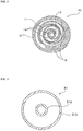
- FIG. 2 is a section view illustrating inside of a scroll compressor shown in FIG.1 .
- the scroll compressor 10 comprises a rotary scroll 11 and a fixed scroll 12, wherein a phase difference of the rotary scroll 11 and the fixed scroll 12 is 180 degree.
- a compression chamber is formed between an involute wrap of the rotary scroll 11 and an involute wrap of the fixed scroll 12.
- the compression chamber is shaped into crescent moon by engaging the rotary scroll 11 and the fixed scroll 12, and is a plurality. Refrigerant inside of the compression chamber is gradually compressed and is charged through an outlet 13 by a rotary motion of the rotary scroll 11.
- first refrigerant injection flow path 52 and the second refrigerant injection flow path 62 respectively injects refrigerant into different place inside of the scroll compressor 10.
- first refrigerant injection flow path 52 may injects refrigerant into any one of a plurality of the compression chambers
- the second refrigerant injection flow path 62 may inject refrigerant into the other of those.
- a first refrigerant injection port 14 into which refrigerant injected by the first refrigerant injection flow path 52 flows is formed at the one side of the scroll compressor, and a second refrigerant injection port 15 is formed at the other side of that.
- the first refrigerant injection port 14 and the second refrigerant injection port 15 may comprise a hole formed in the fixed scroll 12 or the rotary scroll 11.
- first refrigerant injection flow path 52 and the second refrigerant injection flow path 62 can be directly connected to a space between the fixed scroll 12 and the rotary scroll 11.
- the first refrigerant injection port 14 and the second refrigerant injection port 15 may be respectively two ports, but it also may be one port.
- the first refrigerant injection port 14 and the second refrigerant injection port 16 are apart in the direction of the outlet from the inlet of the scroll compressor.
- first refrigerant injection flow path 52 and the second refrigerant injection flow path 62 may comprise a phase separator 51 for separating refrigerant expanded by the first expansion valve 30 into liquid refrigerant and vapor refrigerant.
- the other of the first refrigerant injection flow path 52 and the second refrigerant injection flow path 62 may comprise an internal heat exchanger 61 which is disposed a space between the first expansion valve 30 and the second expansion valve 40 for exchanging heat of refrigerant expanded by the first expansion valve 30.
- first refrigerant injection flow path 52 there is the phase separator 51.
- the first refrigerant injection flow path 52 is connected to the first refrigerant injection port 14.
- the second refrigerant injection flow path 62 comprises the internal heat exchanger 61.
- the second refrigerant injection flow path 62 is connected to the second refrigerant injection flow path 15.
- the phase separator 51 stores refrigerant temporarily, and separates the stored refrigerant into liquid refrigerant and vapor refrigerant, and then discharges only liquid refrigerant to the outside.
- the intake port of the phase separator 51 is connected to a discharge port of the condenser 20 by a fourth refrigerant circulation flow path 24.
- the discharge port of the phase separator 51 is connected to the internal heat exchanger 61 by a fifth refrigerant circulation flow path 25.
- the liquid refrigerant discharged from the phase separator 51 flows into the internal heat exchanger 61 through the fifth refrigerant circulation flow path 25.
- the vapor refrigerant discharged from the phase separator 51 flows into the first refrigerant injection port 15 of the scroll compressor 10 through the first refrigerant injection flow path 52.
- the first refrigerant injection flow path 52 connects the phase separator 51 and the scroll compressor10.
- a first refrigerant control valve 53 is disposed at the first refrigerant injection flow path 52, and throttles the refrigerant passing through the first refrigerant injection flow path 52.
- the flow rate of refrigerant injected into the first refrigerant injection port 15 can be controlled according to an opening degree of the first refrigerant control valve 53.
- a second refrigerant control valve 63 is disposed at the second refrigerant injection flow path 62, and throttles the refrigerant passing through the second refrigerant injection flow path 62.
- the flow rate of refrigerant injected into the second refrigerant injection port 14 can be controlled according to an opening degree of the second refrigerant control valve 63.
- the second refrigerant control valve 63 is disposed before the intake port or after the discharge port of the internal heat exchanger 61.
- the second refrigerant control valve 63 is disposed before the intake port of the internal heat exchanger 61 and throttles refrigerant before refrigerant exchanges heat in the internal heat exchanger.
- the second refrigerant injection flow path 62 is bypassed from the fifth refrigerant circulation flow path 25 so that the refrigerant heat-exchanged in the internal heat exchanger 61 is guided to the second refrigerant injection port 14.
- the internal heat exchanger 61 exchanges heat of the refrigerant passing through the fifth refrigerant circulation flow path 25 with heat of the refrigerant passing through the second refrigerant injection flow path 62.
- the internal heat exchanger 61 may be a plate type heat exchanger or a double pipe type heat exchanger.
- FIG. 3 is a section view illustrating inside of an internal heat exchanger shown in FIG.1 .
- the present invention describes that the internal heat exchanger 61 is a double pipe type heat exchanger which comprises a first refrigerant pipe 61a and a second refrigerant pipe 61b formed to surround the first refrigerant pipe 61a.
- the internal heat exchanger 61 may be a plate type heat exchanger.
- the refrigerant of the second refrigerant injection flow path 62 may pass through any one of the first refrigerant pipe 61a and the second refrigerant pipe 61b, and the refrigerant of the fifth refrigerant circulation flow path 25 may pass through into the other of those.
- the refrigerant of the second refrigerant injection flow path 62 passes through the first refrigerant pipe 61a and the refrigerant of the fifth refrigerant circulation flow path 25 passes through the second refrigerant pipe 61b.
- the discharge port of the internal heat exchanger 61 is connected to the intake port of the evaporator 70 and the sixth refrigerant circulation flow path 26.
- FIG. 4 is a block diagram illustrating the control flow of the air conditioner shown in FIG. 1 .
- the air conditioner 100 further comprises a controller 80 for controlling the overall operation.
- the controller 80 controls an opening amount of the first expansion valve 30 and the second expansion valve 40 and the first refrigerant control valve 53 and the second refrigerant control valve 63 according to the heating load of the air conditioner 100.
- the controller 80 controls that the first the first refrigerant control valve 53 and the second refrigerant control valve 63 are closed and that the first expansion valve 30 and the second expansion valve 40 are fully opened. At the beginning of the operation of the air conditioner 100, it can be prevented that liquid refrigerant flows into the scroll compressor device 10 by closing the first refrigerant control valve 53 and the second refrigerant control valve 63.
- the controller 80 controls that any one of the first refrigerant control valve 53 and the second refrigerant control valve 63 may be opened selectively, or may be opened in serial order, or may be opened simultaneously for quick reaction, according to the heating load such as the outdoor temperature.
- the controller 80 can control the opening degree of the first refrigerant control valve 53 and the second refrigerant control valve 63 according to the heating load.
- FIG. 5 is a schematic diagram illustrating the condition that a first refrigerant control valve is opened and a second refrigerant control valve is closed in the air conditioner shown in FIG.1 .
- FIG. 6 is a schematic diagram illustrating the condition that a first refrigerant control valve and a second refrigerant control valve are opened in the air conditioner shown in FIG.1 .
- the controller 80 controls the first expansion valve 30 and the second expansion valve 40 to be fully opened.
- the controller 80 controls both the first refrigerant control valve 53 and the second refrigerant control valve 63 to be closed.
- the controller 80 controls both the first refrigerant control valve 53 and the second refrigerant control valve 63 to be closed.
- the controller 80 may controls an opening amount of the first expansion valve 30 and the second expansion valve 40 according to the operation of the scroll compressor 10. At this time, the controller 80 has to control that an open degree of the second expansion valve 40 is larger than or equal to an opening degree of the first expansion valve 30.
- the controller 80 controls the degree of superheat for the refrigerant of the air conditioner 100 to be reached to the preset target degree of superheat. And the controller also controls for the refrigerant to be reached to the preset intermediate pressure.
- the degree of superheat is the difference between the temperature of the refrigerant sucked into the scroll compressor 10 and the saturation temperature with respect to the evaporating pressure of the evaporator 70.
- the degree of superheat can be measured by a sensor installed in the evaporator 70 and a sensor installed in the inlet of the scroll compressor 10.
- the refrigerant passed through the evaporator 70 does not include liquid refrigerant. But, if the load is suddenly changed, the refrigerant may include liquid refrigerant.
- the scroll compressor 10 may become damaged.
- the temperature of the refrigerant has to rise so as to eliminate liquid refrigerant. If the amount of refrigerant flowing into the evaporator 70 is decreased, all refrigerants may be evaporated before the refrigerant passes through the evaporator 70. Vapor refrigerants are continuously heated, the degree of superheat may be increased. Therefore, it can be prevented that the liquid refrigerant flows into the scroll compressor 10.
- the degree of superheat may be decreased.
- the controller 80 controls an opening amount of the second expansion valve 40 installed between the phase separator 51 and the evaporator 70 so as to control the degree of superheat.
- the intermediate pressure is a pressure of inside of the phase separator 51.
- the intermediate pressure can be calculated from the temperature measured by the temperature sensor installed in the first refrigerant injection flow path 52. By adapting the intermediate pressure to reach a preset intermediate pressure, the work of scroll compressor 10 can be reduced, thus the efficiency of the scroll compressor 10 may be increased. By adjusting the amount of the refrigerant supplied to the phase separator 51 from the condenser 20, the intermediate pressure can be adjusted.
- the controller 80 adjusts the opening amount of the first expansion valve 30 disposed between the phase separator 51 and the condenser 20 so as to adjust the intermediate pressure.
- the controller 80 may open any one of the first refrigerant control valve 53 and the second refrigerant control valve 63.
- the controller 80 may selects and opens any one of the first refrigerant control valve 53 and the second refrigerant control valve 63 according to the heating load such as the outdoor temperature.
- the controller 80 may open only the first refrigerant control valve 53 and may close the second refrigerant control valve 63.
- the vapor refrigerant separated by the phase separator 51 flows into the first refrigerant injection port 15 through the first refrigerant flow path 52.
- the refrigerant injected into the first refrigerant injection port 15 and the refrigerant in the scroll compressor 10 are mixed and then are compressed.
- the injected refrigerant is vapor refrigerant at the intermediate pressure.
- the liquid refrigerant discharged from the phase separator 51 passes through the internal heat exchanger 61.
- the second refrigerant control valve 63 is closed, the heat exchange is not performed in the inside of the internal heat exchanger 61.
- the controller 80 may also open the second refrigerant control valve 63.
- the second refrigerant control valve 63 If the second refrigerant control valve 63 is opened, the portion of the liquid refrigerant discharged from the phase separator 51 is bypassed to the second refrigerant injection flow path 62 and then is throttled in the second refrigerant control valve 63 and then flows into the internal heat exchanger 61. Because the temperature and the pressure of the refrigerant throttled by the second refrigerant control valve 63 is dropped, the temperature of the refrigerant throttled is lower than the temperature of the refrigerant flowing in the fifth refrigerant circulation flow path 25.
- the refrigerant flowing in the second refrigerant injection flow path 62 and the refrigerant flowing in the fifth refrigerant circulation flow path 25 can exchange the heat of the each.
- the refrigerant flowing in the fifth refrigerant circulation flow path 25 lose the heat
- the refrigerant flowing in the second refrigerant injection flow path 62 absorbs the heat.
- the refrigerant which has lost the heat in the internal heat exchanger 61 is throttled in the second expansion valve 40 and then flows into the evaporator 70.
- the refrigerant in the evaporator 70 is evaporated by heat exchange with ambient air, and the evaporated refrigerant is introduced into the second refrigerant injection port 14.
- the refrigerant which absorbs the heat in the internal heat exchanger 61 is evaporated and becomes two phase refrigerant mixed liquid and vapor or superheated vapor refrigerant or vapor refrigerant.
- the ratio of liquid refrigerant to vapor refrigerant can be minimized by controlling the opening degree of the second refrigerant control valve 63.
- the flow rate of the refrigerant injected from the internal heat exchanger 61 is more than the flow rate of the refrigerant injected from the phase separator 51. Total flow rate of the refrigerant injecting into the compressor is increased, and thus the heating performance can be improved.
- the refrigerant flowed into the second refrigerant injection flow path 62 is injected into the second refrigerant injection port 14 of the scroll compressor 13.
- the refrigerant injected into the second refrigerant injection port 14 and the refrigerant in the scroll compressor 10 are mixed and are compressed. Because the injected and compressed refrigerant is the refrigerant at the intermediate pressure, the difference between the suction pressure and the discharge pressure of the scroll compressor 10 can be decreased.
- the flow rate can be increased.
- the heating performance can be improved by an increase of flow rate.
- the heat pump is an air conditioner.
- the present invention is not limited thereto, the heat pump can be applied to a cooling and heating air conditioner comprising a 4-way valve.
- the heat pump comprises two refrigerant injection flow paths.
- the heat pump further comprises a third refrigerant injection flow path which is separated from the first refrigerant flow path and the second refrigerant flow path.
- FIG. 7 is a schematic diagram illustrating the configuration of an air conditioner according to a second exemplary embodiment of the present invention.
- the first injection device 200 comprises a phase separator 201 and a first refrigerant injection flow path 202 which is bypassed from the phase separator 201 and connects to the second refrigerant injection port 14 of the scroll compressor 10.
- the second injection device 210 comprises an internal heat exchanger 211 which is disposed inside of the phase separator 201 and absorbs heat generated from the phase separator 201 and the second refrigerant injection flow path 212 which connects the internal heat exchanger 211 with the first refrigerant injection port 15 of the scroll compressor 10.
- Detailed description about the same elements as the first exemplary embodiment is skipped. A same number in figures indicates the same element.
- a first refrigerant control valve 203 for throttling the injecting refrigerant is disposed at the first refrigerant injection flow path 202.
- a second refrigerant control valve 213 for throttling the injecting refrigerant is disposed at the second refrigerant injection flow path 212.
- phase separator 201 and the internal heat exchanger 211 are formed to one unit, the structure can be simplified. Also, the heat generated from the phase separator 201 can be utilized.
- FIG. 8 is a schematic diagram illustrating the configuration of an air conditioner according to an alternative heat pump, which is not part of the present invention.
- an air conditioner according to an alternative heat pump which is not part of the present invention, comprises a refrigerant circulation flow path 136 which connects the first expansion valve 30 and the second expansion valve 40 and a third heat exchanger 137 which is disposed at the refrigerant circulation flow path 136.
- a first refrigerant injection flow path 221 comprises a first heat exchanger 222, which is disposed at the first refrigerant injection flow path 221 for exchanging heat of the refrigerant passing through the first refrigerant injection flow path 221 and heat of the refrigerant passing through the refrigerant circulation flow path 136, and a first refrigerant control valve 223 for throttling the refrigerant passing through the first refrigerant injection flow path 221.
- a second refrigerant injection flow path 231 comprises a second heat exchanger 232, which is disposed at the second refrigerant injection flow path 231 for exchanging heat of the refrigerant passing through the second refrigerant injection flow path 231 and heat of the refrigerant passing through the refrigerant circulation flow path 136, and a second refrigerant control valve 233 for throttling the refrigerant passing through the second refrigerant injection flow path 231.
- the first heat exchanger 222 and the second heat exchanger 232 and the third heat exchanger 137 are respectively in the shape of a plate.
- the first heat exchanger 222 and the second heat exchanger 232 and the third heat exchanger 137 are formed in a body.
- the first heat exchanger 222 is disposed at the one side of the third heat exchanger 137, and the second heat exchanger 232 is disposed at the other side of the third heat exchanger 137.
- FIG. 9 is a schematic diagram illustrating the configuration of an air conditioner according to an alternative heat pump, which is not part of the present invention.
- FIG. 10 is a section view illustrating a triple pipe heat exchanger shown in FIG. 9 .
- an air conditioner according to an alternative heat pump which is not part of the present invention, comprises a triple pipe heat exchanger 250 which is disposed at the space between the first expansion device 30 and the second expansion device 40. Detailed description about the same elements as in the previous alternative heat pump is skipped. A same number in figures indicates the same element.
- the triple pipe heat exchanger 250 comprises a first refrigerant pipe 251 forming the first refrigerant injection flow path 221, and a second refrigerant pipe 252 surrounding the first refrigerant pipe 251 and introducing refrigerant passed through the first expansion device 30, and a third refrigerant pipe 253 surrounding the second refrigerant pipe 252 and forming the second refrigerant injection flow path 231.
- the triple pipe heat exchanger 250 comprising the first refrigerant pipe 251 and the second refrigerant pipe 252 and the third refrigerant pipe 253, a structure of the air conditioner can be simplified.
- FIG. 11 is a schematic diagram illustrating the configuration of an air conditioner according to the present invention.
- a heat pump according to the present invention comprises an air conditioner 100, and a water heater 300 which uses water heated by the condenser 20 for heating the water, and a heater 400 which uses water heated by the condenser 20 for heating the floor. Detailed description about the same elements as previously is skipped. A same number in figures indicates the same element.
- the water heater 300 and the heater 400 are connected to the condenser 20 by a hot water circulation flow path 301.
- the hot water circulation flow path 301 connects the condenser 20 and the water heater 300 and the heater 400 so that hot water heated by the condenser passes through any one of the water heater 300 and the heater 400 and then returns to the condenser 20.
- the hot water circulation flow path 301 comprises an indoor unit pipe 302 which is disposed in the inside of the air conditioner 100, and a water heater pipe 303 for introducing a hot water to the water heater 300, and a heater pipe 304 for introducing a hot water to the heater 400, and a connection pipe 305 for connecting the indoor unit pipe 302 to the water heater pipe 303 and the heater pipe 304.
- a hot water control valve 306 is installed at the connection pipe 305 for introducing a hot water to any one of the water heater pipe 303 and the heater pipe 304.
- the water heater 300 is a device for supplying a hot water needed to wash and bath or dish-washing.
- the water heater 300 comprises a hot water tank 310 for storing water and a sub heater 312 installed in the hot water tank 310.
- the hot water tank 310 is connected with a cold water inlet 314 for introducing cold water to the hot water tank 310 and a hot water outlet 316 for discharging hot water.
- the hot water outlet 316 may be connected with a hot water discharge apparatus 318 such as a shower.
- the hot water outlet 316 may be connected with the cold water inlet 320 so as to discharge cold water to the hot water discharge apparatus 318.
- the heater 400 comprises a floor heater 410 for heating a floor in the room and an air heater 412 for heating an air in the room.
- the floor heater 410 may be laid under the floor by the meander line.
- the air heater 412 may comprise a fan coil unit or a radiator.
- a hot water control valve for heating 411/421 may be installed at the heater pipe 304 for introducing the hot water to any one of the floor heater 410 and the air heater 420.
- the floor heater 410 is connected to the hot water control valve for heating 411 and the floor heating pipe 412, and the air heater 420 is connected to the hot water control valve for heating 421 and the air heating pipe 422.
- the hot water control valve 306 is controlled with a heating mode, the water heated by the condenser 30 passes through the indoor pipe 302 and the connection pipe 305 in order, and heats any one of the floor heater 410 and the air heater 420, and passes through the heater pipe 304 and the connection pipe 305 and the indoor pipe 302 in order, and then is returned to the condenser 20.
- hot water control valve for heating 411/412 is controlled with a air heating mode
- hot water passes through the air heating pipe 422 and the air heater 420 and air heating pipe 422 in order, and is discharged to the heating pipe 304.
- it is controlled with a floor heating mode
- hot water passes through the floor heating pipe 412 and the floor heater 411 and the floor heating pipe 412 in order, and is discharged to the heating pipe 304.
- refrigerant is also injected through the first refrigerant injection flow path 52 and the second injection flow path 62. Therefore, by injecting refrigerant, a flow rate of the refrigerant can be increased and a performance of the water heating and the heating can be improved.
Landscapes
- Engineering & Computer Science (AREA)
- Mechanical Engineering (AREA)
- General Engineering & Computer Science (AREA)
- Physics & Mathematics (AREA)
- Thermal Sciences (AREA)
- Compression-Type Refrigeration Machines With Reversible Cycles (AREA)
- Rotary Pumps (AREA)
Claims (4)
- Wärmepumpe, umfassend:einen Hauptkreislauf, welcher einen Scrollkompressor (10) und einen Kondensator (20) zum Kondensieren von Kühlmittel umfasst, welches den Scrollkompressor (10) und eine Expansionsvorrichtung (30, 40) zum Expandieren von Kühlmittel passiert hat, welches den Kondensator (20) und einen Verdampfer (70) zum Verdampfen von durch die Expansionsvorrichtung (30, 40) expandiertem Kühlmittel passiert hat;einen ersten Kühlmittelinjektionsströmungspfad (52), welcher zwischen dem Kondensator (20) und dem Verdampfer (70) von dem Hauptkreislauf überbrückt ist und zwischen einem Einlass und einem Auslass des Scrollkompressors (10) mit einem ersten Kühlmittelinjektionsanschluss (14) verbunden ist;einen zweiten Kühlmittelinjektionsströmungspfad (62), welcher zwischen dem Kondensator (20) und dem Verdampfer (70) von dem Hauptkreislauf überbrückt ist und zwischen dem Einlass und dem Auslass des Scrollkompressors (10) mit einem zweiten Kühlmittelinjektionsanschluss (15) verbunden ist;wobei ein Phasenseparator (51) zwischen dem Kondensator (20) und dem Verdampfer (70) angeordnet ist, von welchem der erste Kühlmittelinjektionsströmungspfad (52) überbrückt ist, und ein interner Wärmetauscher (61) zwischen dem Phasenseparator (51) und dem Verdampfer (70) angeordnet ist,dadurch gekennzeichnet, dass der zweite Kühlmittelinjektionsströmungspfad (62) von einem Kühlmittelzirkulationsströmungspfad (25) überbrückt ist, welcher stromabwärts des Phasenseparators (51) platziert ist, und dann den internen Wärmetauscher (61) passiert, wobei ein Kühlmittel-Steuer-/Regelventil (63) zwischen dem Kühlmittelzirkulationsströmungspfad (25) und dem internen Wärmetauscher (61) in dem zweiten Kühlmittelinjektionsströmungspfad (62) installiert ist.
- Wärmepumpe nach Anspruch 1,
wobei die Expansionsvorrichtung eine erste Expansionsvorrichtung (30), welche zwischen dem Kondensator (20) und dem Phasenseparator (51) angeordnet ist, und eine zweite Expansionsvorrichtung (40) umfasst, welche zwischen dem internen Wärmetauscher (61) und dem Verdampfer (70) angeordnet ist. - Wärmepumpe nach Anspruch 1,wobei der interne Wärmetauscher (61) eine erste Kühlmittelleitung (61a) und eine zweite Kühlmittelleitung (61b) umfasst, welche derart gebildet ist, dass sie die erste Kühlmittelleitung (61a) umgibt,und wobei jegliches des Kühlmittels, welches von dem internen Wärmetauscher (61) zu dem Verdampfer (70) strömt, und des Kühlmittels, welches in den Scrollkompressor (10) injiziert wird, die erste Kühlmittelleitung (61a) passiert und das übrige dieses Kühlmittels die zweite Kühlmittelleitung (61b) passiert.
- Wärmepumpe nach Anspruch 1,ferner umfassend eine Wassererwärmungseinheit (300) und eine Erwärmungseinheit (400), welche durch einen Warmwasserzirkulationsströmungspfad (305) mit dem Kondensator (20) verbunden sind, wobei die Wassererwärmungseinheit (300) einen Warmwasserbehälter (310) zur Aufnahme warmen Wassers umfasst und die Erwärmungseinheit (400) eine Lufterwärmungseinheit (420) zum Erwärmen einer Luft in einem Raum umfasst,wobei ein Steuer-/Regelventil (306) in dem Warmwasserzirkulationsströmungspfad (305) installiert ist, um das in dem Kondensator (20) erwärmte warme Wasser in wenigstens eine der Wassererwärmungseinheit (300) und der Erwärmungseinheit (400) einzuführen.
Applications Claiming Priority (1)
| Application Number | Priority Date | Filing Date | Title |
|---|---|---|---|
| KR1020090111605A KR101280381B1 (ko) | 2009-11-18 | 2009-11-18 | 히트 펌프 |
Publications (3)
| Publication Number | Publication Date |
|---|---|
| EP2325577A2 EP2325577A2 (de) | 2011-05-25 |
| EP2325577A3 EP2325577A3 (de) | 2014-05-21 |
| EP2325577B1 true EP2325577B1 (de) | 2017-08-30 |
Family
ID=43770508
Family Applications (1)
| Application Number | Title | Priority Date | Filing Date |
|---|---|---|---|
| EP10251357.9A Not-in-force EP2325577B1 (de) | 2009-11-18 | 2010-07-30 | Wärmepumpe |
Country Status (4)
| Country | Link |
|---|---|
| US (1) | US8789382B2 (de) |
| EP (1) | EP2325577B1 (de) |
| KR (1) | KR101280381B1 (de) |
| CN (1) | CN102062497B (de) |
Families Citing this family (45)
| Publication number | Priority date | Publication date | Assignee | Title |
|---|---|---|---|---|
| KR101212698B1 (ko) | 2010-11-01 | 2013-03-13 | 엘지전자 주식회사 | 히트 펌프식 급탕장치 |
| US20120103005A1 (en) * | 2010-11-01 | 2012-05-03 | Johnson Controls Technology Company | Screw chiller economizer system |
| KR101203579B1 (ko) | 2010-11-05 | 2012-11-21 | 엘지전자 주식회사 | 공조 겸용 급탕 장치 및 그 운전방법 |
| KR101212681B1 (ko) * | 2010-11-08 | 2012-12-17 | 엘지전자 주식회사 | 공기조화기 |
| JP2012233676A (ja) * | 2011-04-21 | 2012-11-29 | Denso Corp | ヒートポンプサイクル |
| JP5240332B2 (ja) * | 2011-09-01 | 2013-07-17 | ダイキン工業株式会社 | 冷凍装置 |
| KR101278337B1 (ko) | 2011-10-04 | 2013-06-25 | 엘지전자 주식회사 | 스크롤 압축기 및 이를 포함하는 공기 조화기 |
| WO2013063668A1 (en) * | 2011-11-01 | 2013-05-10 | Whirlpool S.A. | Refrigeration system |
| CN103175323B (zh) * | 2011-12-23 | 2017-03-01 | 东普雷股份有限公司 | 使用三重管式热交换器的制冷装置 |
| CN104246395B (zh) * | 2012-03-15 | 2016-08-24 | 三菱电机株式会社 | 制冷循环装置 |
| KR101352052B1 (ko) * | 2012-06-25 | 2014-01-16 | 한국과학기술원 | 막힘 현상을 해소한 극저온 줄-톰슨 냉동 장치 |
| KR20140022619A (ko) * | 2012-08-14 | 2014-02-25 | 삼성전자주식회사 | 공기조화기 및 공기조화기의 제어방법 |
| JP5494770B2 (ja) * | 2012-09-25 | 2014-05-21 | 三菱電機株式会社 | ヒートポンプ給湯機 |
| US9885504B2 (en) * | 2012-12-31 | 2018-02-06 | Trane International Inc. | Heat pump with water heating |
| KR102032282B1 (ko) * | 2013-04-12 | 2019-10-15 | 엘지전자 주식회사 | 스크롤 압축기 |
| KR102163859B1 (ko) * | 2013-04-15 | 2020-10-12 | 엘지전자 주식회사 | 공기조화기 및 그 제어방법 |
| KR102103360B1 (ko) * | 2013-04-15 | 2020-05-29 | 엘지전자 주식회사 | 공기조화기 및 그 제어방법 |
| JP5949648B2 (ja) * | 2013-04-18 | 2016-07-13 | 株式会社デンソー | 冷凍サイクル装置 |
| KR102068234B1 (ko) | 2013-10-07 | 2020-01-20 | 엘지전자 주식회사 | 스크롤 압축기 및 이를 포함하는 공기 조화기 |
| CN103775344A (zh) * | 2014-01-24 | 2014-05-07 | 南通四方冷链装备股份有限公司 | 高温螺杆压缩机系统及其喷液冷却装置 |
| KR102240070B1 (ko) * | 2014-03-20 | 2021-04-13 | 엘지전자 주식회사 | 공기조화기 및 그 제어방법 |
| CN103851828B (zh) * | 2014-03-28 | 2016-08-17 | 广东华天成新能源科技股份有限公司 | 一种喷气增焓联供系统 |
| JP2016065659A (ja) * | 2014-09-24 | 2016-04-28 | 東芝キヤリア株式会社 | ヒートポンプ装置 |
| CN105526740B (zh) * | 2014-09-28 | 2020-01-10 | 浙江盾安人工环境股份有限公司 | 蒸发器及包含该蒸发器的空调器 |
| KR101710254B1 (ko) * | 2015-01-12 | 2017-02-24 | 엘지전자 주식회사 | 스크롤 압축기 및 이를 포함하는 공기 조화기 |
| KR101702736B1 (ko) | 2015-01-12 | 2017-02-03 | 엘지전자 주식회사 | 공기 조화기 |
| JP6318107B2 (ja) * | 2015-03-17 | 2018-04-25 | ヤンマー株式会社 | ヒートポンプ |
| CN105066493A (zh) * | 2015-08-31 | 2015-11-18 | 广东美的暖通设备有限公司 | 一种空调系统 |
| JP6555584B2 (ja) * | 2015-09-11 | 2019-08-07 | パナソニックIpマネジメント株式会社 | 冷凍装置 |
| JP6814974B2 (ja) * | 2015-09-11 | 2021-01-20 | パナソニックIpマネジメント株式会社 | 冷凍装置 |
| KR101613205B1 (ko) * | 2015-10-22 | 2016-04-18 | 주식회사 성지테크 | 증발 응축기 일체형 히트 펌프 |
| US11105544B2 (en) * | 2016-11-07 | 2021-08-31 | Trane International Inc. | Variable orifice for a chiller |
| US20180187927A1 (en) * | 2017-01-03 | 2018-07-05 | Heatcraft Refrigeration Products Llc | System and method for reusing waste heat of a transcritical refrigeration system |
| BR202017006118Y1 (pt) | 2017-03-24 | 2022-12-20 | Whirlpool S.A. | Evaporador para sistema de refrigeração |
| FR3068442A1 (fr) * | 2017-06-30 | 2019-01-04 | Enertime | Dispositif de refroidissement combine a une production de vapeur |
| CN107476971B (zh) * | 2017-08-14 | 2023-06-06 | 天津大学 | 一种兼具补气和中间排气功能的涡旋式压缩机及热泵系统 |
| KR101991445B1 (ko) * | 2018-03-02 | 2019-06-20 | 엘지전자 주식회사 | 스크롤 압축기 |
| US11384969B2 (en) | 2020-02-27 | 2022-07-12 | Heatcraft Refrigeration Products Llc | Cooling system with oil return to oil reservoir |
| US11371756B2 (en) | 2020-02-27 | 2022-06-28 | Heatcraft Refrigeration Products Llc | Cooling system with oil return to accumulator |
| JP2021139542A (ja) * | 2020-03-04 | 2021-09-16 | 株式会社富士通ゼネラル | 空気調和装置 |
| CN111595047A (zh) * | 2020-06-19 | 2020-08-28 | 深圳市英维克科技股份有限公司 | 一种冷藏车的制冷系统及其控制方法 |
| KR102431510B1 (ko) * | 2020-12-03 | 2022-08-12 | 엘지전자 주식회사 | 스크롤 압축기 및 이를 구비한 공기조화장치 |
| EP4334652A4 (de) | 2021-05-03 | 2024-08-14 | Matthew Desmarais | Doppelhybridwärmepumpen und systeme sowie verfahren zur verwendung und zum betrieb |
| CN114857793B (zh) * | 2022-05-20 | 2023-03-31 | 珠海格力电器股份有限公司 | 一种冷凝机组及其喷液控制方法、控制装置和空调器 |
| CN116086101A (zh) * | 2023-04-12 | 2023-05-09 | 云南道精制冷科技有限责任公司 | 一种制取1~2℃冰水的方法 |
Family Cites Families (86)
| Publication number | Priority date | Publication date | Assignee | Title |
|---|---|---|---|---|
| US3177674A (en) * | 1964-03-09 | 1965-04-13 | Gen Electric | Refrigeration system including charge checking means |
| US3188829A (en) * | 1964-03-12 | 1965-06-15 | Carrier Corp | Conditioning apparatus |
| US3301002A (en) * | 1965-04-26 | 1967-01-31 | Carrier Corp | Conditioning apparatus |
| US4098092A (en) * | 1976-12-09 | 1978-07-04 | Singh Kanwal N | Heating system with water heater recovery |
| US4134274A (en) * | 1978-01-26 | 1979-01-16 | The Trane Company | System for producing refrigeration and a heated liquid and control therefor |
| US4238933A (en) * | 1978-03-03 | 1980-12-16 | Murray Coombs | Energy conserving vapor compression air conditioning system |
| US4249390A (en) * | 1979-08-23 | 1981-02-10 | Jones William M | Air conditioning system |
| US4299098A (en) * | 1980-07-10 | 1981-11-10 | The Trane Company | Refrigeration circuit for heat pump water heater and control therefor |
| US4399664A (en) * | 1981-12-07 | 1983-08-23 | The Trane Company | Heat pump water heater circuit |
| US4493193A (en) * | 1982-03-05 | 1985-01-15 | Rutherford C. Lake, Jr. | Reversible cycle heating and cooling system |
| US4409796A (en) * | 1982-03-05 | 1983-10-18 | Rutherford C. Lake, Jr. | Reversible cycle heating and cooling system |
| US4492092A (en) * | 1982-07-02 | 1985-01-08 | Carrier Corporation | Combination refrigerant circuit and hot water preheater |
| US4787444A (en) * | 1983-12-19 | 1988-11-29 | Countryman James H | Heating and cooling system |
| US4528822A (en) * | 1984-09-07 | 1985-07-16 | American-Standard Inc. | Heat pump refrigeration circuit with liquid heating capability |
| GB8511729D0 (en) | 1985-05-09 | 1985-06-19 | Svenska Rotor Maskiner Ab | Screw rotor compressor |
| US4598557A (en) * | 1985-09-27 | 1986-07-08 | Southern Company Services, Inc. | Integrated heat pump water heater |
| US4646537A (en) * | 1985-10-31 | 1987-03-03 | American Standard Inc. | Hot water heating and defrost in a heat pump circuit |
| US4766734A (en) * | 1987-09-08 | 1988-08-30 | Electric Power Research Institute, Inc. | Heat pump system with hot water defrost |
| US4940079A (en) * | 1988-08-11 | 1990-07-10 | Phenix Heat Pump Systems, Inc. | Optimal control system for refrigeration-coupled thermal energy storage |
| US5243827A (en) * | 1989-07-31 | 1993-09-14 | Hitachi, Ltd. | Overheat preventing method for prescribed displacement type compressor and apparatus for the same |
| JP2618501B2 (ja) * | 1989-10-30 | 1997-06-11 | 株式会社日立製作所 | 低温用スクロール式冷凍装置 |
| JPH0448160A (ja) * | 1990-06-14 | 1992-02-18 | Hitachi Ltd | 冷凍サイクル装置 |
| US5056329A (en) | 1990-06-25 | 1991-10-15 | Battelle Memorial Institute | Heat pump systems |
| JPH04110574A (ja) * | 1990-08-30 | 1992-04-13 | Union Kogyo Kk | 冷媒ガスを用いた加熱冷却方法及び装置 |
| US5184472A (en) * | 1991-01-08 | 1993-02-09 | Pierre Guilbault | Add on heat pump swimming pool heater control |
| JPH04117195U (ja) * | 1991-04-02 | 1992-10-20 | サンデン株式会社 | スクロール型圧縮機 |
| US5269153A (en) * | 1991-05-22 | 1993-12-14 | Artesian Building Systems, Inc. | Apparatus for controlling space heating and/or space cooling and water heating |
| US5211029A (en) * | 1991-05-28 | 1993-05-18 | Lennox Industries Inc. | Combined multi-modal air conditioning apparatus and negative energy storage system |
| JPH0593549A (ja) * | 1991-10-02 | 1993-04-16 | Hitachi Ltd | 冷凍装置 |
| US5329788A (en) * | 1992-07-13 | 1994-07-19 | Copeland Corporation | Scroll compressor with liquid injection |
| JPH07167513A (ja) * | 1993-12-16 | 1995-07-04 | Hitachi Ltd | 冷凍装置 |
| US5465588A (en) * | 1994-06-01 | 1995-11-14 | Hydro Delta Corporation | Multi-function self-contained heat pump system with microprocessor control |
| JPH0821665A (ja) * | 1994-07-05 | 1996-01-23 | Hitachi Ltd | 冷凍装置のスクロール圧縮機の吐出ガス温度制御方法及び装置 |
| CA2128178A1 (en) * | 1994-07-15 | 1996-01-16 | Michel Antoine Grenier | Ground source heat pump system |
| US5467812A (en) * | 1994-08-19 | 1995-11-21 | Lennox Industries Inc. | Air conditioning system with thermal energy storage and load leveling capacity |
| US5495723A (en) * | 1994-10-13 | 1996-03-05 | Macdonald; Kenneth | Convertible air conditioning unit usable as water heater |
| US5758514A (en) * | 1995-05-02 | 1998-06-02 | Envirotherm Heating & Cooling Systems, Inc. | Geothermal heat pump system |
| US5640854A (en) * | 1995-06-07 | 1997-06-24 | Copeland Corporation | Scroll machine having liquid injection controlled by internal valve |
| US5722257A (en) * | 1995-10-11 | 1998-03-03 | Denso Corporation | Compressor having refrigerant injection ports |
| US5653120A (en) * | 1996-01-03 | 1997-08-05 | Carrier Corporation | Heat pump with liquid refrigerant reservoir |
| US5669224A (en) * | 1996-06-27 | 1997-09-23 | Ontario Hydro | Direct expansion ground source heat pump |
| JP3965717B2 (ja) * | 1997-03-19 | 2007-08-29 | 株式会社日立製作所 | 冷凍装置及び冷凍機 |
| US5802864A (en) * | 1997-04-01 | 1998-09-08 | Peregrine Industries, Inc. | Heat transfer system |
| US5848537A (en) * | 1997-08-22 | 1998-12-15 | Carrier Corporation | Variable refrigerant, intrastage compression heat pump |
| US5937670A (en) * | 1997-10-09 | 1999-08-17 | International Comfort Products Corporation (Usa) | Charge balance device |
| US5899091A (en) * | 1997-12-15 | 1999-05-04 | Carrier Corporation | Refrigeration system with integrated economizer/oil cooler |
| US6058727A (en) * | 1997-12-19 | 2000-05-09 | Carrier Corporation | Refrigeration system with integrated oil cooling heat exchanger |
| US5996364A (en) * | 1998-07-13 | 1999-12-07 | Carrier Corporation | Scroll compressor with unloader valve between economizer and suction |
| US6374631B1 (en) * | 2000-03-27 | 2002-04-23 | Carrier Corporation | Economizer circuit enhancement |
| JP2002021753A (ja) * | 2000-07-11 | 2002-01-23 | Fujitsu General Ltd | スクロール圧縮機 |
| CN1133047C (zh) * | 2001-03-14 | 2003-12-31 | 清华同方股份有限公司 | 一种适用于寒冷地区的热泵空调机组 |
| US6601397B2 (en) * | 2001-03-16 | 2003-08-05 | Copeland Corporation | Digital scroll condensing unit controller |
| US6615602B2 (en) * | 2001-05-22 | 2003-09-09 | Ken Wilkinson | Heat pump with supplemental heat source |
| JP3801006B2 (ja) * | 2001-06-11 | 2006-07-26 | ダイキン工業株式会社 | 冷媒回路 |
| US6564563B2 (en) * | 2001-06-29 | 2003-05-20 | International Business Machines Corporation | Logic module refrigeration system with condensation control |
| JP2003130477A (ja) * | 2001-10-30 | 2003-05-08 | Hitachi Ltd | 冷凍装置 |
| CN2529164Y (zh) * | 2002-03-19 | 2003-01-01 | 清华同方股份有限公司 | 用于寒冷地区的热泵空调机组 |
| US6571576B1 (en) * | 2002-04-04 | 2003-06-03 | Carrier Corporation | Injection of liquid and vapor refrigerant through economizer ports |
| US6694750B1 (en) * | 2002-08-21 | 2004-02-24 | Carrier Corporation | Refrigeration system employing multiple economizer circuits |
| JP4048160B2 (ja) * | 2002-08-22 | 2008-02-13 | 帝人コードレ株式会社 | 皮革様シート状物およびその製造方法 |
| US6923011B2 (en) * | 2003-09-02 | 2005-08-02 | Tecumseh Products Company | Multi-stage vapor compression system with intermediate pressure vessel |
| US6892553B1 (en) * | 2003-10-24 | 2005-05-17 | Carrier Corporation | Combined expansion device and four-way reversing valve in economized heat pumps |
| US6817205B1 (en) * | 2003-10-24 | 2004-11-16 | Carrier Corporation | Dual reversing valves for economized heat pump |
| US7000423B2 (en) * | 2003-10-24 | 2006-02-21 | Carrier Corporation | Dual economizer heat exchangers for heat pump |
| US7024877B2 (en) * | 2003-12-01 | 2006-04-11 | Tecumseh Products Company | Water heating system |
| TWI325949B (en) * | 2004-02-09 | 2010-06-11 | Sanyo Electric Co | Refrigerant system |
| JP4771721B2 (ja) * | 2005-03-16 | 2011-09-14 | 三菱電機株式会社 | 空気調和装置 |
| US7726151B2 (en) * | 2005-04-05 | 2010-06-01 | Tecumseh Products Company | Variable cooling load refrigeration cycle |
| JP4614441B2 (ja) * | 2005-06-10 | 2011-01-19 | 日立アプライアンス株式会社 | スクロール圧縮機 |
| WO2007046812A2 (en) * | 2005-10-18 | 2007-04-26 | Carrier Corporation | Economized refrigerant vapor compression system for water heating |
| JP2007139225A (ja) * | 2005-11-15 | 2007-06-07 | Hitachi Ltd | 冷凍装置 |
| JP5093549B2 (ja) * | 2006-01-05 | 2012-12-12 | レシップホールディングス株式会社 | 運賃箱 |
| US8322150B2 (en) | 2006-03-27 | 2012-12-04 | Carrier Corporation | Refrigerating system with parallel staged economizer circuits discharging to interstage pressures of a main compressor |
| US7647790B2 (en) * | 2006-10-02 | 2010-01-19 | Emerson Climate Technologies, Inc. | Injection system and method for refrigeration system compressor |
| US8181478B2 (en) * | 2006-10-02 | 2012-05-22 | Emerson Climate Technologies, Inc. | Refrigeration system |
| US8381538B2 (en) * | 2006-11-08 | 2013-02-26 | Carrier Corporation | Heat pump with intercooler |
| JP4254863B2 (ja) * | 2007-01-23 | 2009-04-15 | ダイキン工業株式会社 | 空気調和装置 |
| US8517087B2 (en) * | 2007-02-20 | 2013-08-27 | Bergstrom, Inc. | Combined heating and air conditioning system for vehicles |
| WO2008105868A2 (en) | 2007-02-26 | 2008-09-04 | Carrier Corporation | Economized refrigerant system utilizing expander with intermediate pressure port |
| CN101617183B (zh) * | 2007-02-28 | 2011-07-27 | 开利公司 | 制冷剂系统和控制方法 |
| KR100883600B1 (ko) | 2007-03-08 | 2009-02-13 | 엘지전자 주식회사 | 공기조화기 |
| EP1978317B1 (de) * | 2007-04-06 | 2017-09-06 | Samsung Electronics Co., Ltd. | Kältekreislaufvorrichtung |
| JP2009036140A (ja) * | 2007-08-03 | 2009-02-19 | Hitachi Appliances Inc | スクロール圧縮機および空気調和機 |
| JP5200593B2 (ja) * | 2008-03-13 | 2013-06-05 | アイシン精機株式会社 | 空気調和装置 |
| US8539785B2 (en) * | 2009-02-18 | 2013-09-24 | Emerson Climate Technologies, Inc. | Condensing unit having fluid injection |
| EP2468946B1 (de) * | 2010-12-27 | 2014-05-07 | Electrolux Home Products Corporation N.V. | Wärmepumpensystem für einen Wäschetrockner und Verfahren zum Betreiben eines Wäschetrockners mit Wärmepumpe |
-
2009
- 2009-11-18 KR KR1020090111605A patent/KR101280381B1/ko active IP Right Grant
-
2010
- 2010-03-19 CN CN2010101384782A patent/CN102062497B/zh active Active
- 2010-07-29 US US12/846,638 patent/US8789382B2/en not_active Expired - Fee Related
- 2010-07-30 EP EP10251357.9A patent/EP2325577B1/de not_active Not-in-force
Non-Patent Citations (1)
| Title |
|---|
| None * |
Also Published As
| Publication number | Publication date |
|---|---|
| US8789382B2 (en) | 2014-07-29 |
| KR20110054818A (ko) | 2011-05-25 |
| EP2325577A2 (de) | 2011-05-25 |
| KR101280381B1 (ko) | 2013-07-01 |
| CN102062497B (zh) | 2013-06-12 |
| CN102062497A (zh) | 2011-05-18 |
| US20110113808A1 (en) | 2011-05-19 |
| EP2325577A3 (de) | 2014-05-21 |
Similar Documents
| Publication | Publication Date | Title |
|---|---|---|
| EP2325577B1 (de) | Wärmepumpe | |
| EP2325578B1 (de) | Wärmepumpe | |
| US10401067B2 (en) | Air conditioner | |
| EP2083230B1 (de) | Klimaanlagensystem | |
| EP2479517B1 (de) | Klimaanlage | |
| US8424333B2 (en) | Air conditioner | |
| US9416990B2 (en) | Hot water supply apparatus associated with heat pump | |
| EP2829821B1 (de) | Wärmepumpe | |
| KR101288681B1 (ko) | 공기조화기 | |
| US9267720B2 (en) | Air conditioner and method of controlling the same | |
| JP2023503192A (ja) | 空気調和装置 | |
| KR101186331B1 (ko) | 냉난방 동시형 멀티 공기조화기 | |
| KR101450543B1 (ko) | 공기조화 시스템 | |
| KR20120053381A (ko) | 냉동 사이클 장치 | |
| KR102587026B1 (ko) | 히트 펌프를 이용한 항온항습 공기조화기 및 그의 제어 방법 | |
| KR20110062457A (ko) | 히트 펌프 시스템 | |
| KR102536079B1 (ko) | 복합 칠러 시스템 및 이의 동작 방법 | |
| KR101450545B1 (ko) | 공기조화 시스템 | |
| KR20210077358A (ko) | 냉난방 장치 | |
| US20240027077A1 (en) | Hybrid multi-air conditioning system and method for controlling a hybrid multi-air conditioning system | |
| CN111306033A (zh) | 双级压缩机及制冷装置 | |
| US20240230190A9 (en) | Air conditioner | |
| KR101397658B1 (ko) | 공기조화 시스템 | |
| KR101460717B1 (ko) | 공기조화 시스템 | |
| KR20100062079A (ko) | 냉난방 겸용 인젝션 타입 공기조화기 및 그 공기조화기의 인젝션 모드 절환방법 |
Legal Events
| Date | Code | Title | Description |
|---|---|---|---|
| PUAI | Public reference made under article 153(3) epc to a published international application that has entered the european phase |
Free format text: ORIGINAL CODE: 0009012 |
|
| AK | Designated contracting states |
Kind code of ref document: A2 Designated state(s): AL AT BE BG CH CY CZ DE DK EE ES FI FR GB GR HR HU IE IS IT LI LT LU LV MC MK MT NL NO PL PT RO SE SI SK SM TR |
|
| REG | Reference to a national code |
Ref country code: DE Ref legal event code: R079 Ref document number: 602010044798 Country of ref document: DE Free format text: PREVIOUS MAIN CLASS: F25B0001100000 Ipc: F25B0030020000 |
|
| PUAL | Search report despatched |
Free format text: ORIGINAL CODE: 0009013 |
|
| AK | Designated contracting states |
Kind code of ref document: A3 Designated state(s): AL AT BE BG CH CY CZ DE DK EE ES FI FR GB GR HR HU IE IS IT LI LT LU LV MC MK MT NL NO PL PT RO SE SI SK SM TR |
|
| RIC1 | Information provided on ipc code assigned before grant |
Ipc: F25B 30/02 20060101AFI20140414BHEP Ipc: F25B 1/04 20060101ALI20140414BHEP Ipc: F25B 1/10 20060101ALI20140414BHEP |
|
| 17P | Request for examination filed |
Effective date: 20141118 |
|
| RBV | Designated contracting states (corrected) |
Designated state(s): AL AT BE BG CH CY CZ DE DK EE ES FI FR GB GR HR HU IE IS IT LI LT LU LV MC MK MT NL NO PL PT RO SE SI SK SM TR |
|
| GRAP | Despatch of communication of intention to grant a patent |
Free format text: ORIGINAL CODE: EPIDOSNIGR1 |
|
| INTG | Intention to grant announced |
Effective date: 20170216 |
|
| GRAS | Grant fee paid |
Free format text: ORIGINAL CODE: EPIDOSNIGR3 |
|
| GRAA | (expected) grant |
Free format text: ORIGINAL CODE: 0009210 |
|
| AK | Designated contracting states |
Kind code of ref document: B1 Designated state(s): AL AT BE BG CH CY CZ DE DK EE ES FI FR GB GR HR HU IE IS IT LI LT LU LV MC MK MT NL NO PL PT RO SE SI SK SM TR |
|
| REG | Reference to a national code |
Ref country code: GB Ref legal event code: FG4D |
|
| REG | Reference to a national code |
Ref country code: CH Ref legal event code: EP |
|
| REG | Reference to a national code |
Ref country code: AT Ref legal event code: REF Ref document number: 923942 Country of ref document: AT Kind code of ref document: T Effective date: 20170915 |
|
| REG | Reference to a national code |
Ref country code: IE Ref legal event code: FG4D |
|
| REG | Reference to a national code |
Ref country code: DE Ref legal event code: R096 Ref document number: 602010044798 Country of ref document: DE |
|
| REG | Reference to a national code |
Ref country code: NL Ref legal event code: MP Effective date: 20170830 |
|
| REG | Reference to a national code |
Ref country code: LT Ref legal event code: MG4D |
|
| REG | Reference to a national code |
Ref country code: AT Ref legal event code: MK05 Ref document number: 923942 Country of ref document: AT Kind code of ref document: T Effective date: 20170830 |
|
| PG25 | Lapsed in a contracting state [announced via postgrant information from national office to epo] |
Ref country code: NO Free format text: LAPSE BECAUSE OF FAILURE TO SUBMIT A TRANSLATION OF THE DESCRIPTION OR TO PAY THE FEE WITHIN THE PRESCRIBED TIME-LIMIT Effective date: 20171130 Ref country code: AT Free format text: LAPSE BECAUSE OF FAILURE TO SUBMIT A TRANSLATION OF THE DESCRIPTION OR TO PAY THE FEE WITHIN THE PRESCRIBED TIME-LIMIT Effective date: 20170830 Ref country code: FI Free format text: LAPSE BECAUSE OF FAILURE TO SUBMIT A TRANSLATION OF THE DESCRIPTION OR TO PAY THE FEE WITHIN THE PRESCRIBED TIME-LIMIT Effective date: 20170830 Ref country code: SE Free format text: LAPSE BECAUSE OF FAILURE TO SUBMIT A TRANSLATION OF THE DESCRIPTION OR TO PAY THE FEE WITHIN THE PRESCRIBED TIME-LIMIT Effective date: 20170830 Ref country code: LT Free format text: LAPSE BECAUSE OF FAILURE TO SUBMIT A TRANSLATION OF THE DESCRIPTION OR TO PAY THE FEE WITHIN THE PRESCRIBED TIME-LIMIT Effective date: 20170830 Ref country code: HR Free format text: LAPSE BECAUSE OF FAILURE TO SUBMIT A TRANSLATION OF THE DESCRIPTION OR TO PAY THE FEE WITHIN THE PRESCRIBED TIME-LIMIT Effective date: 20170830 |
|
| PG25 | Lapsed in a contracting state [announced via postgrant information from national office to epo] |
Ref country code: IS Free format text: LAPSE BECAUSE OF FAILURE TO SUBMIT A TRANSLATION OF THE DESCRIPTION OR TO PAY THE FEE WITHIN THE PRESCRIBED TIME-LIMIT Effective date: 20171230 Ref country code: LV Free format text: LAPSE BECAUSE OF FAILURE TO SUBMIT A TRANSLATION OF THE DESCRIPTION OR TO PAY THE FEE WITHIN THE PRESCRIBED TIME-LIMIT Effective date: 20170830 Ref country code: BG Free format text: LAPSE BECAUSE OF FAILURE TO SUBMIT A TRANSLATION OF THE DESCRIPTION OR TO PAY THE FEE WITHIN THE PRESCRIBED TIME-LIMIT Effective date: 20171130 Ref country code: ES Free format text: LAPSE BECAUSE OF FAILURE TO SUBMIT A TRANSLATION OF THE DESCRIPTION OR TO PAY THE FEE WITHIN THE PRESCRIBED TIME-LIMIT Effective date: 20170830 Ref country code: GR Free format text: LAPSE BECAUSE OF FAILURE TO SUBMIT A TRANSLATION OF THE DESCRIPTION OR TO PAY THE FEE WITHIN THE PRESCRIBED TIME-LIMIT Effective date: 20171201 |
|
| PG25 | Lapsed in a contracting state [announced via postgrant information from national office to epo] |
Ref country code: NL Free format text: LAPSE BECAUSE OF FAILURE TO SUBMIT A TRANSLATION OF THE DESCRIPTION OR TO PAY THE FEE WITHIN THE PRESCRIBED TIME-LIMIT Effective date: 20170830 |
|
| PG25 | Lapsed in a contracting state [announced via postgrant information from national office to epo] |
Ref country code: CZ Free format text: LAPSE BECAUSE OF FAILURE TO SUBMIT A TRANSLATION OF THE DESCRIPTION OR TO PAY THE FEE WITHIN THE PRESCRIBED TIME-LIMIT Effective date: 20170830 Ref country code: PL Free format text: LAPSE BECAUSE OF FAILURE TO SUBMIT A TRANSLATION OF THE DESCRIPTION OR TO PAY THE FEE WITHIN THE PRESCRIBED TIME-LIMIT Effective date: 20170830 Ref country code: DK Free format text: LAPSE BECAUSE OF FAILURE TO SUBMIT A TRANSLATION OF THE DESCRIPTION OR TO PAY THE FEE WITHIN THE PRESCRIBED TIME-LIMIT Effective date: 20170830 Ref country code: RO Free format text: LAPSE BECAUSE OF FAILURE TO SUBMIT A TRANSLATION OF THE DESCRIPTION OR TO PAY THE FEE WITHIN THE PRESCRIBED TIME-LIMIT Effective date: 20170830 |
|
| PG25 | Lapsed in a contracting state [announced via postgrant information from national office to epo] |
Ref country code: IT Free format text: LAPSE BECAUSE OF FAILURE TO SUBMIT A TRANSLATION OF THE DESCRIPTION OR TO PAY THE FEE WITHIN THE PRESCRIBED TIME-LIMIT Effective date: 20170830 Ref country code: SK Free format text: LAPSE BECAUSE OF FAILURE TO SUBMIT A TRANSLATION OF THE DESCRIPTION OR TO PAY THE FEE WITHIN THE PRESCRIBED TIME-LIMIT Effective date: 20170830 Ref country code: EE Free format text: LAPSE BECAUSE OF FAILURE TO SUBMIT A TRANSLATION OF THE DESCRIPTION OR TO PAY THE FEE WITHIN THE PRESCRIBED TIME-LIMIT Effective date: 20170830 Ref country code: SM Free format text: LAPSE BECAUSE OF FAILURE TO SUBMIT A TRANSLATION OF THE DESCRIPTION OR TO PAY THE FEE WITHIN THE PRESCRIBED TIME-LIMIT Effective date: 20170830 |
|
| REG | Reference to a national code |
Ref country code: DE Ref legal event code: R097 Ref document number: 602010044798 Country of ref document: DE |
|
| REG | Reference to a national code |
Ref country code: FR Ref legal event code: PLFP Year of fee payment: 9 |
|
| PLBE | No opposition filed within time limit |
Free format text: ORIGINAL CODE: 0009261 |
|
| STAA | Information on the status of an ep patent application or granted ep patent |
Free format text: STATUS: NO OPPOSITION FILED WITHIN TIME LIMIT |
|
| 26N | No opposition filed |
Effective date: 20180531 |
|
| PG25 | Lapsed in a contracting state [announced via postgrant information from national office to epo] |
Ref country code: SI Free format text: LAPSE BECAUSE OF FAILURE TO SUBMIT A TRANSLATION OF THE DESCRIPTION OR TO PAY THE FEE WITHIN THE PRESCRIBED TIME-LIMIT Effective date: 20170830 |
|
| REG | Reference to a national code |
Ref country code: CH Ref legal event code: PL |
|
| GBPC | Gb: european patent ceased through non-payment of renewal fee |
Effective date: 20180730 |
|
| PG25 | Lapsed in a contracting state [announced via postgrant information from national office to epo] |
Ref country code: LU Free format text: LAPSE BECAUSE OF NON-PAYMENT OF DUE FEES Effective date: 20180730 Ref country code: MC Free format text: LAPSE BECAUSE OF FAILURE TO SUBMIT A TRANSLATION OF THE DESCRIPTION OR TO PAY THE FEE WITHIN THE PRESCRIBED TIME-LIMIT Effective date: 20170830 |
|
| REG | Reference to a national code |
Ref country code: BE Ref legal event code: MM Effective date: 20180731 |
|
| PG25 | Lapsed in a contracting state [announced via postgrant information from national office to epo] |
Ref country code: LI Free format text: LAPSE BECAUSE OF NON-PAYMENT OF DUE FEES Effective date: 20180731 Ref country code: GB Free format text: LAPSE BECAUSE OF NON-PAYMENT OF DUE FEES Effective date: 20180730 Ref country code: CH Free format text: LAPSE BECAUSE OF NON-PAYMENT OF DUE FEES Effective date: 20180731 |
|
| REG | Reference to a national code |
Ref country code: IE Ref legal event code: MM4A |
|
| PG25 | Lapsed in a contracting state [announced via postgrant information from national office to epo] |
Ref country code: BE Free format text: LAPSE BECAUSE OF NON-PAYMENT OF DUE FEES Effective date: 20180731 |
|
| PG25 | Lapsed in a contracting state [announced via postgrant information from national office to epo] |
Ref country code: IE Free format text: LAPSE BECAUSE OF NON-PAYMENT OF DUE FEES Effective date: 20180730 |
|
| PG25 | Lapsed in a contracting state [announced via postgrant information from national office to epo] |
Ref country code: MT Free format text: LAPSE BECAUSE OF NON-PAYMENT OF DUE FEES Effective date: 20180730 |
|
| PG25 | Lapsed in a contracting state [announced via postgrant information from national office to epo] |
Ref country code: TR Free format text: LAPSE BECAUSE OF FAILURE TO SUBMIT A TRANSLATION OF THE DESCRIPTION OR TO PAY THE FEE WITHIN THE PRESCRIBED TIME-LIMIT Effective date: 20170830 |
|
| PG25 | Lapsed in a contracting state [announced via postgrant information from national office to epo] |
Ref country code: HU Free format text: LAPSE BECAUSE OF FAILURE TO SUBMIT A TRANSLATION OF THE DESCRIPTION OR TO PAY THE FEE WITHIN THE PRESCRIBED TIME-LIMIT; INVALID AB INITIO Effective date: 20100730 Ref country code: PT Free format text: LAPSE BECAUSE OF FAILURE TO SUBMIT A TRANSLATION OF THE DESCRIPTION OR TO PAY THE FEE WITHIN THE PRESCRIBED TIME-LIMIT Effective date: 20170830 |
|
| PG25 | Lapsed in a contracting state [announced via postgrant information from national office to epo] |
Ref country code: MK Free format text: LAPSE BECAUSE OF NON-PAYMENT OF DUE FEES Effective date: 20170830 Ref country code: CY Free format text: LAPSE BECAUSE OF FAILURE TO SUBMIT A TRANSLATION OF THE DESCRIPTION OR TO PAY THE FEE WITHIN THE PRESCRIBED TIME-LIMIT Effective date: 20170830 |
|
| PG25 | Lapsed in a contracting state [announced via postgrant information from national office to epo] |
Ref country code: AL Free format text: LAPSE BECAUSE OF FAILURE TO SUBMIT A TRANSLATION OF THE DESCRIPTION OR TO PAY THE FEE WITHIN THE PRESCRIBED TIME-LIMIT Effective date: 20170830 |
|
| PGFP | Annual fee paid to national office [announced via postgrant information from national office to epo] |
Ref country code: FR Payment date: 20200609 Year of fee payment: 11 |
|
| PGFP | Annual fee paid to national office [announced via postgrant information from national office to epo] |
Ref country code: DE Payment date: 20200605 Year of fee payment: 11 |
|
| REG | Reference to a national code |
Ref country code: DE Ref legal event code: R119 Ref document number: 602010044798 Country of ref document: DE |
|
| PG25 | Lapsed in a contracting state [announced via postgrant information from national office to epo] |
Ref country code: DE Free format text: LAPSE BECAUSE OF NON-PAYMENT OF DUE FEES Effective date: 20220201 |
|
| PG25 | Lapsed in a contracting state [announced via postgrant information from national office to epo] |
Ref country code: FR Free format text: LAPSE BECAUSE OF NON-PAYMENT OF DUE FEES Effective date: 20210731 |