EP2325397B1 - System und Verfahren zur Installation von Fundamentselementen in einer Unterwasserbodenschicht - Google Patents
System und Verfahren zur Installation von Fundamentselementen in einer Unterwasserbodenschicht Download PDFInfo
- Publication number
- EP2325397B1 EP2325397B1 EP09176850A EP09176850A EP2325397B1 EP 2325397 B1 EP2325397 B1 EP 2325397B1 EP 09176850 A EP09176850 A EP 09176850A EP 09176850 A EP09176850 A EP 09176850A EP 2325397 B1 EP2325397 B1 EP 2325397B1
- Authority
- EP
- European Patent Office
- Prior art keywords
- pump
- underpressure
- hydraulic cylinder
- hydraulic
- impact weight
- Prior art date
- Legal status (The legal status is an assumption and is not a legal conclusion. Google has not performed a legal analysis and makes no representation as to the accuracy of the status listed.)
- Active
Links
Images


Classifications
-
- E—FIXED CONSTRUCTIONS
- E02—HYDRAULIC ENGINEERING; FOUNDATIONS; SOIL SHIFTING
- E02D—FOUNDATIONS; EXCAVATIONS; EMBANKMENTS; UNDERGROUND OR UNDERWATER STRUCTURES
- E02D7/00—Methods or apparatus for placing sheet pile bulkheads, piles, mouldpipes, or other moulds
- E02D7/02—Placing by driving
- E02D7/06—Power-driven drivers
- E02D7/10—Power-driven drivers with pressure-actuated hammer, i.e. the pressure fluid acting directly on the hammer structure
-
- E—FIXED CONSTRUCTIONS
- E02—HYDRAULIC ENGINEERING; FOUNDATIONS; SOIL SHIFTING
- E02D—FOUNDATIONS; EXCAVATIONS; EMBANKMENTS; UNDERGROUND OR UNDERWATER STRUCTURES
- E02D7/00—Methods or apparatus for placing sheet pile bulkheads, piles, mouldpipes, or other moulds
- E02D7/02—Placing by driving
Definitions
- the invention relates to a system for and a method of installing or removing (decommissioning) foundation elements, such as piles, anchors, and conductors, in a subsea ground formation.
- Systems (denoted by numeral 1 in Figures 1 and 2 ) of this type are generally known and usually comprise an impact weight (2), a hydraulic cylinder (3), a piston (4) reciprocatingly accommodated in the hydraulic cylinder (3) and connected to the impact weight (2), high and low pressure accumulators (5, 6), often also referred to as feed and return accumulators (5, 6), a valve system (7) for alternately connecting the hydraulic cylinder (3) to the high and low pressure accumulators (5, 6), a tank (8) for a hydraulic medium, such as hydraulic oil, and a pump (9) for pressurizing the hydraulic medium, i.e. for providing the hydraulic energy required to operate the system.
- a hydraulic medium such as hydraulic oil
- the valve system (7) comprises a reversing valve for alternately supplying the hydraulic medium to the cylinder spaces above and below the piston (4).
- the pressure in and hence the 'stiffness' of the system in particular the pressure in the accumulators and, if present, the gas spring, increases with increasing depth. At extreme depths, such as 1500 meters and deeper, the pressure in the system causes several problems. E.g., it is no longer possible to fill the accumulators from pre-filled gas cylinders. High pressure compressors are required instead.
- the system according to the present invention comprises a pump for generating an underpressure in the hydraulic cylinder such as to lift and/or accelerate the impact weight by means of this underpressure.
- suitable pumps include electrically or hydraulically driven piston pumps.
- the (relative) underpressure that can be generated by means of the pump increases with increasing depth.
- Current systems work with pressure differences of at least 50 bar.
- the pump for generating an underpressure is positioned or positionable at a depth of at least 500 meters, preferably at least 1000 meters below sea level.
- the pump is preferably integrated in a so-called underwater power pack which receives electrical or hydraulic power from a surface vessel or facility via e.g. an umbilical or drill string.
- the pump for generating an underpressure is positioned or positionable at a depth of less than 1000 meters, preferably less than 500 meters above the hydraulic cylinder and more preferably at substantially the same depth as the hydraulic cylinder.
- the hydraulic cylinder is connected, e.g. via or in conjunction with a high pressure accumulator and a valve, also to the pressure line of the pump for generating an underpressure, i.e. a single pump is employed to generate both an underpressure on one side of the piston in the hydraulic cylinder and a relatively high pressure on the other side of the piston, obtaining a 'closed loop'.
- the system comprises a regulator for maintaining the amount of hydraulic fluid in the hydraulic circuit at a substantially constant level.
- a unit known as scavenger
- systems for subsea installation and removal of foundation elements comprise a unit, known as scavenger, for withdrawing hydraulic fluid from the circuit and subsequently treating, e.g. cooling, filtering, dewatering, degassing, and/or returning the fluid.
- the regulator is integrated in this unit.
- the invention further relates to a method of installing or removing foundation elements, such as piles, anchors, and conductors, in a subsea ground formation, by means of a hydraulic driver comprising an impact weight, a hydraulic cylinder, and a piston accommodated in the hydraulic cylinder and connected to the impact weight, which method comprises the steps of mounting the impact driver on a foundation element, driving the foundation element into respectively out of the ground formation by alternately lifting and accelerating the impact weight respectively away from and towards the element, wherein the impact weight is lifted and/or accelerated by means of an underpressure above respectively beneath the piston.
- a hydraulic driver comprising an impact weight, a hydraulic cylinder, and a piston accommodated in the hydraulic cylinder and connected to the impact weight
- GB 2 078 148 relates to a drop hammer apparatus, wherein a hammer (E) is interconnected with a piston (B) by means of a piston rod.
- An upright cylinder (A) is open at its upper end, the piston is slidable within the cylinder and the piston rod is slidable through the lower end of the cylinder.
- the space within the cylinder below the piston is selectively connected to a source (C) of pressurized liquid e.g. water and exhausted by means of a valve (D).
- GB 1 397 137 discloses an apparatus for the driving of piles underwater and comprising a hollow tube connected to the pile, the tube being sequentially evacuated by pump and filled with ambient water by opening a valve at the end of the tube, the incoming water, when it strikes the lower end of the tube or any residual water therein producing a driving pulse.
- the embodiment shown in Figure 13 involves repetitively and alternately raising a piston (160) with a winch (125) and dropping the piston. Raising of the piston evacuates an enclosure defined by the pile tip and side walls. Quick release of the piston and rapid descent thereof through the pile accelerate a mass of water above the piston.
- US 3,820,346 As similar system is shown in US 3,820,346 .
- GB 2 069 902 relates to a submersible hammer (21) for driving piles comprising a piston (36) and cylinder (35) assembly provided in conjunction with a ram (30) to move the same upwardly when the piston is lifted.
- Sea water is supplied as power medium at a pressure in excess of the ambient pressure and an inlet valve (50) effects fluid communication between the pressurized sea water and the piston to lift the piston, and thus the ram, and to terminate such communication when the piston reaches a predetermined level.
- An exhaust valve (51) vents the sea water allowing the piston and ram to fall until the ram impacts the upper end of a pile to drive the same into the sea bed.
- GB 1 452 777 relates to a gas discharge powered pile driver comprising an "airgun”.
- WO 2004/051004 discloses a "pile-driving apparatus comprising a pile, a shoe tip coupled to a toe of the pile, and a drill string disposed within the pile.”
- US 4,964,473 relates to a method for driving a hydraulic submerged tool, wherein the hydraulic pressure energy is generated in a submerged power converter.
- US 4,089,165 relates to a water pressure-powered pile driving hammer. The piston of the pile driving hammer is raised by hydraulic (water) pressure.
- the hammer is movable upwards and downwards in a housing which, in operation, is filled with a liquid which is present both above and below the hammer, the hammer being driven at least on the upwards direction by a driving liquid which is pressurized by a motor driven pump located on or adjacent the housing and which is the same as the liquid in which the hammer moves.
- a driving liquid which is pressurized by a motor driven pump located on or adjacent the housing and which is the same as the liquid in which the hammer moves.
- Other prior art relating to underwater pile driving includes EP 301 114 , EP 301 116 and US 4,043,405 .
- underpressure is defined as a pressure lower than the pressure that prevails in the surroundings of the system. It is noted that in prior art systems underpressure can arise e.g. from inertia of moving components, in particular from the ram at the end of lifting or directly after impact when bouncing upwards. However, these effects are small compared to the underpressure generated by a pump in accordance with the present invention and insufficient to drive the impact weight autonomously.
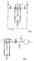
- Figure 3 shows a first embodiment of the system 1 according to the present invention, which comprises an impact weight 2, a hydraulic cylinder 3, a piston 4 reciprocatingly accommodated in the hydraulic cylinder 3 and connected to the impact weight 2 by means of a rod 4A, high and low pressure accumulators 5, 6, and first and second valves 7A, 7B for alternately connecting the cylinder space beneath the piston 4 in the hydraulic cylinder 3 to the high and low pressure accumulators 5, 6.
- the system further comprises a tank 8 for a hydraulic medium, such as hydraulic oil, a first or feed pump 9 for pressurizing the hydraulic medium and connected, via the high pressure accumulator 5 and the first valve 7A, to the hydraulic cylinder 3, a gas spring or "cap” 10 above the piston 4, and a second pump 11 for generating an underpressure in the hydraulic cylinder 3.
- a hydraulic medium such as hydraulic oil
- a first or feed pump 9 for pressurizing the hydraulic medium and connected, via the high pressure accumulator 5 and the first valve 7A, to the hydraulic cylinder 3, a gas spring or "cap” 10 above the piston 4, and a second pump 11 for generating an underpressure in the hydraulic cylinder 3.
- the high pressure accumulator 5 communicates with the cylinder space beneath the piston 4 and the piston 4 and impact weight 2 are lifted by the hydraulic medium and the medium, typically air or water, surrounding (the tip of) the impact weight against the action of the gas spring 10.
- the hydraulic medium is withdrawn from beneath the piston 4 by the underpressure in the return accumulator 6 and the suction line of the second pump 11 and the impact weight 2 is accelerated by the gas spring 10 in opposite direction, i.e. typically towards a foundation element.
- the pump can generate an underpressure of up to approximately 200 bar, enabling operating pressures in the high and low pressure accumulators and the cap of approximately 180 bar, 2 bar, and 185 bar, respectively.
- the pressure of the hydraulic medium beneath the piston is reduced almost to zero and said sum of pressures results in a force smaller than the force resulting from the gas pressure in the cap.
- the pump can generate an underpressure of up to approximately 100 bar, still enabling operating pressures as low as approximately 280 bar, 200 bar, and 100 bar, respectively.
- Figure 4 shows a hydraulically driven system 1 comprising a second pump 11 for generating an underpressure in the low pressure accumulator 6 and a 4/2 valve 7 for alternately connecting the cylinder spaces beneath and above the piston 4 in the hydraulic cylinder 3 to the high and low pressure accumulators 5, 6, thus lifting the impact weight and reversing the connections to accelerate it in opposite direction.
- pressures are obtainable similar to those in the Table above, e.g. with the hammer and the pump at a depth of 2000 meters and the pump operating at maximum capacity the pressures in the high and low pressure accumulators amount to approximately 180 bar and 2 bar, respectively.
- the systems according to the present invention can be simplified by connecting the hydraulic cylinder 3 not just to the suction line of the pump 11 for generating an underpressure but also to its pressure line.
- a single pump fulfils the tasks of generating an underpressure on the low pressure (hydraulic fluid outlet) side of the hydraulic cylinder and a relatively high pressure on the high pressure (hydraulic fluid inlet) side of the hydraulic cylinder thus obtaining a 'closed loop'.
- a scavenger is preferably added to the system for withdrawing hydraulic fluid from the circuit and subsequently treating, e.g. cooling, filtering, dewatering and/or degassing, the fluid. Further, it is preferred that the scavenger is arranged to maintain the amount of hydraulic fluid in the hydraulic circuit at a substantially constant level, inter alia to prevent the free pistons in the accumulators from hitting the bottoms of the accumulators.
- the system can be simplified even further by omitting the high pressure accumulator and the corresponding valve.
- the system can be operated merely by means of the valve 7B between the hydraulic cylinder 3 and the low pressure accumulator 6.
- this valve 7B When this valve 7B is closed, the pressure line of the pump 11 communicates with the cylinder space beneath the piston 4 and the piston 4 and impact weight 2 are lifted by the hydraulic medium against the action of the gas spring 10.
- the valve 7B is open, the hydraulic medium is withdrawn from beneath the piston 4 by the underpressure in the return accumulator and the suction line of the pump 11, i.e. the hydraulic medium is circulated through the system by the pump, and the impact weight is accelerated by the gas spring.
- the gas spring can also be omitted by establishing fluid communication between the cylinder space above the piston and the surroundings, e.g. by a hydraulic cylinder that is open at one end.
- the impact weight is accessible for water from the surroundings such that, during operation, the weight reciprocates in water. Although dissipation is thus increased, the system no longer requires the feeding of gas to the hammer.
- the hydraulic circuit is arranged to withdraw water from and exhaust water to the surroundings, i.e. seawater is employed as the hydraulic medium for driving the impact weight.
- water withdrawn from the surroundings passes through a filter 13 first.
Landscapes
- Engineering & Computer Science (AREA)
- Life Sciences & Earth Sciences (AREA)
- General Life Sciences & Earth Sciences (AREA)
- Mining & Mineral Resources (AREA)
- Paleontology (AREA)
- Civil Engineering (AREA)
- General Engineering & Computer Science (AREA)
- Structural Engineering (AREA)
- Placing Or Removing Of Piles Or Sheet Piles, Or Accessories Thereof (AREA)
- Earth Drilling (AREA)
- Other Liquid Machine Or Engine Such As Wave Power Use (AREA)
Claims (14)
- System (1) zum Installieren oder Entfernen von Fundamentelementen, zum Beispiel von Pfählen, Verankerungen und Leitungen in einer Unterseebodenformation, aufweisend ein Stoßgewicht (2), einen Hydraulikkreislauf, der wiederum einen Hydraulikzylinder (3) zum Anheben und/oder Beschleunigen des Stoßgewichtes (2) von dem Element weg bzw. in Richtung zu dem Element aufweist, wobei der Zylinder (3) einen Kolben (4) aufweist, der in dem Hydraulikzylinder (3) aufgenommen ist und mit dem Stoßgewicht (2) verbunden ist, und gekennzeichnet durch eine Pumpe (11) zum Erzeugen eines Unterdrucks in dem Hydraulikzylinder (3), um das Stoßgewicht (2) mittels des Unterdrucks anzuheben und/oder zu beschleunigen.
- System (1) gemäß Anspruch 1, wobei die Pumpe (11) zum Erzeugen eines Unterdrucks in einer Tiefe von mindestens 500 Metern, vorzugsweise mindestens 1000 Metern unter dem Meeresspiegel positioniert ist oder positionierbar ist.
- System (1) gemäß Anspruch 1 oder 2, wobei die Pumpe (11) zum Erzeugen eines Unterdrucks in einer Tiefe von weniger als 1000 Metern, vorzugsweise weniger als 500 Metern über und mehr bevorzugt in im Wesentlichen der gleichen Tiefe wie der Hydraulikzylinder (3) positioniert ist oder positionierbar ist.
- System (1) gemäß irgendeinem der vorhergehenden Ansprüche, wobei der Hydraulikzylinder (3) mit der Druckleitung der Pumpe (11) zum Erzeugen eines Unterdrucks verbunden ist.
- System (1) gemäß Anspruch 4, aufweisend einen Regulator zum Halten der Menge an Hydraulikfluid, das in dem Hydraulikkreislauf enthalten ist, auf einem im Wesentlichen konstanten Pegel.
- System (1) gemäß Anspruch 5, aufweisend eine Einheit zum Entnehmen von Hydraulikfluid aus dem Kreislauf, zum Behandeln und Zurückleiten des Fluids, wobei der Regulator in die Einheit integriert ist oder Teil der Einheit ist.
- System (1) gemäß irgendeinem der vorhergehenden Ansprüche, wobei der Hydraulikzylinder (3) direkt mit einer Speisepumpe (9, 11), einem Kompensator (12) oder der Umgebung verbunden ist.
- System (1) gemäß irgendeinem der vorhergehenden Ansprüche, wobei das Stoßgewicht (2), wenn es untergetaucht ist, für Wasser aus der Umgebung zugänglich ist, so dass sich das Gewicht (2) in Wasser hin und her bewegt.
- System gemäß irgendeinem der vorhergehenden Ansprüche, wobei der Hydraulikkreislauf angeordnet ist, um Wasser aus der Umgebung abzuziehen und Wasser in die Umgebung auszustoßen.
- Verfahren zum Installieren oder Entfernen von Fundamentelementen, zum Beispiel von Pfählen, Verankerungen und Leitungen in einer Unterseebodenformation mittels eines hydraulischen Antreibers (2 bis 4), aufweisend ein Stoßgewicht (2), einen Hydraulikzylinder (3) und einen Kolben (4), der in dem Hydraulikzylinder (3) aufgenommen ist und mit dem Stoßgewicht (2) verbunden ist, wobei das Verfahren die folgenden Schritte aufweist:Montieren des Stoßantreibers (2 bis 4) an einem Fundamentelement,Treiben des Fundamentelements in die beziehungsweise aus der Bodenformation heraus durch abwechselndes Anheben und Beschleunigen des Stoßgewichtes (2) von dem Element weg bzw. auf das Element zu,dadurch gekennzeichnet, dass
das Stoßgewicht (2) mittels eines Unterdrucks über bzw. unter dem Kolben (4) angehoben und/oder beschleunigt wird, der von einer Pumpe (11) erzeugt wird. - Verfahren gemäß Anspruch 10, wobei der Unterdruck mittels einer Pumpe (11) erzeugt wird, die in einer Tiefe von mindestens 500 Metern, vorzugsweise von mindestens 1000 Metern unter dem Meeresspiegel positioniert ist.
- Verfahren gemäß Anspruch 10 oder 11, wobei der Unterdruck mittels einer Pumpe (11) erzeugt wird, die in einer Tiefe von weniger als 1000 Metern, vorzugsweise weniger als 500 Metern über und noch bevorzugter im Wesentlichen in der gleichen Tiefe wie der Hydraulikzylinder (3) positioniert ist.
- Verfahren gemäß irgendeinem der Ansprüche 10 bis 12, wobei sich das Stoßgewicht (2) in Wasser hin und her bewegt.
- Verfahren gemäß irgendeinem der Ansprüche 10 bis 13, wobei der Antreiber (2 bis 4) mittels aus der Umgebung entnommenen Wassers betätigt wird.
Priority Applications (5)
| Application Number | Priority Date | Filing Date | Title |
|---|---|---|---|
| EP09176850A EP2325397B1 (de) | 2009-11-24 | 2009-11-24 | System und Verfahren zur Installation von Fundamentselementen in einer Unterwasserbodenschicht |
| DK09176850.7T DK2325397T3 (da) | 2009-11-24 | 2009-11-24 | System og fremgangsmåde til installering af fundamentelementer i en undersøisk grunddannelse |
| MX2010012524A MX2010012524A (es) | 2009-11-24 | 2010-11-17 | Sistema y metodo de instalacion de elementos de cimentacion en una formacion del suelo submarino. |
| BRPI1004854-5A BRPI1004854B1 (pt) | 2009-11-24 | 2010-11-22 | sistema e método para instalar ou remover elementos de fundação |
| US12/952,256 US8562257B2 (en) | 2009-11-24 | 2010-11-23 | System for and method of installing foundation elements in a subsea ground formation |
Applications Claiming Priority (1)
| Application Number | Priority Date | Filing Date | Title |
|---|---|---|---|
| EP09176850A EP2325397B1 (de) | 2009-11-24 | 2009-11-24 | System und Verfahren zur Installation von Fundamentselementen in einer Unterwasserbodenschicht |
Publications (2)
| Publication Number | Publication Date |
|---|---|
| EP2325397A1 EP2325397A1 (de) | 2011-05-25 |
| EP2325397B1 true EP2325397B1 (de) | 2012-08-15 |
Family
ID=42083969
Family Applications (1)
| Application Number | Title | Priority Date | Filing Date |
|---|---|---|---|
| EP09176850A Active EP2325397B1 (de) | 2009-11-24 | 2009-11-24 | System und Verfahren zur Installation von Fundamentselementen in einer Unterwasserbodenschicht |
Country Status (5)
| Country | Link |
|---|---|
| US (1) | US8562257B2 (de) |
| EP (1) | EP2325397B1 (de) |
| BR (1) | BRPI1004854B1 (de) |
| DK (1) | DK2325397T3 (de) |
| MX (1) | MX2010012524A (de) |
Families Citing this family (9)
| Publication number | Priority date | Publication date | Assignee | Title |
|---|---|---|---|---|
| NL2006017C2 (en) * | 2011-01-17 | 2012-07-18 | Ihc Holland Ie Bv | Pile driver system for and method of installing foundation elements in a subsea ground formation. |
| US9535180B2 (en) * | 2013-02-22 | 2017-01-03 | Cgg Services Sa | Method and system for pneumatic control for vibrator source element |
| US20130199813A1 (en) * | 2013-03-04 | 2013-08-08 | Global Piling Solutions, L.L.C. | Hydraulic Hammer |
| CN104047909B (zh) * | 2014-05-27 | 2016-08-24 | 上海朗信基础设备制造有限公司 | 双回路双蓄能器液压系统及液压夯实机 |
| US20160208793A1 (en) * | 2015-01-21 | 2016-07-21 | Caterpillar Inc. | Hydraulic Drive for Cryogenic Fuel Pump |
| US9789932B2 (en) * | 2015-11-25 | 2017-10-17 | Cameron International Corporation | System and method for installing suction piles |
| CN111059085A (zh) * | 2019-12-26 | 2020-04-24 | 太重(天津)重型装备科技开发有限公司 | 集成式液压打桩锤用蓄能器装置 |
| US12523138B2 (en) * | 2022-12-29 | 2026-01-13 | Halliburton Energy Services, Inc. | Autonomous start of pump-down operation |
| CN116792362A (zh) * | 2023-06-29 | 2023-09-22 | 徐州徐工挖掘机械有限公司 | 一种往复驱动装置、破碎锤、打桩锤及夯土机 |
Family Cites Families (17)
| Publication number | Priority date | Publication date | Assignee | Title |
|---|---|---|---|---|
| US3820346A (en) | 1971-07-16 | 1974-06-28 | Orb Inc | Free piston water hammer pile driving |
| US3824797A (en) | 1971-07-16 | 1974-07-23 | Orb Inc | Evacuated tube water hammer pile driving |
| US3817335A (en) | 1972-11-28 | 1974-06-18 | Bolt Associates Inc | Airgun repeater powered pile driver |
| NL180448C (nl) | 1974-11-16 | 1987-02-16 | Koehring Gmbh | Heiinrichting met waterdicht huis en een door druk aangedreven slaglichaam. |
| US4089165A (en) | 1976-12-06 | 1978-05-16 | Reineke Jr Harry W | Water pressure-powered pile driving hammer |
| GB2043510B (en) | 1979-02-27 | 1982-12-22 | Hollandsche Betongroep Nv | Pile driving apparatus |
| GB2069034B (en) * | 1980-02-08 | 1984-02-08 | Bsp Int Foundation | Pile drivers |
| GB2078148A (en) | 1980-02-14 | 1982-01-06 | Delva & Co Engineering Ltd | Drop hammer |
| GB2069902A (en) | 1980-02-22 | 1981-09-03 | Raymond Int Builders | Submersible hammer |
| JPS58210214A (ja) * | 1982-06-02 | 1983-12-07 | Hitachi Constr Mach Co Ltd | 油圧ハンマの操作回路 |
| EP0301114B1 (de) | 1987-07-28 | 1991-07-03 | Menck Gmbh | Verfahren zum Eintreiben von Rammteilen unter Wasser |
| DE3771217D1 (de) | 1987-07-28 | 1991-08-08 | Menck Gmbh | Tauchfaehige elektrohydraulische antriebseinheit fuer zum unterwassereinsatz ausgelegte ramm- und arbeitsgeraete. |
| NL8800632A (nl) | 1988-03-15 | 1989-10-02 | Ihc Holland Nv | Werkwijze voor het aandrijven van een hydraulisch onderwater werktuig. |
| RU2109105C1 (ru) * | 1996-08-14 | 1998-04-20 | Акционерное общество закрытого типа "Российская патентованная техника" | Гидромолот |
| EP1567724A2 (de) | 2002-12-02 | 2005-08-31 | Bj Services Company | Vorrichtung und verfahren zum pfahlrammen untersee |
| EP1621677A1 (de) * | 2004-07-27 | 2006-02-01 | IHC Holland IE B.V. | Vorrichtung und Verfahren zur Einrichtung von Bauelementen |
| EP1748109A1 (de) * | 2005-07-25 | 2007-01-31 | Nederlandse Organisatie voor Toegepast-Natuuurwetenschappelijk Onderzoek TNO | Pfahlramme |
-
2009
- 2009-11-24 EP EP09176850A patent/EP2325397B1/de active Active
- 2009-11-24 DK DK09176850.7T patent/DK2325397T3/da active
-
2010
- 2010-11-17 MX MX2010012524A patent/MX2010012524A/es active IP Right Grant
- 2010-11-22 BR BRPI1004854-5A patent/BRPI1004854B1/pt not_active IP Right Cessation
- 2010-11-23 US US12/952,256 patent/US8562257B2/en active Active
Also Published As
| Publication number | Publication date |
|---|---|
| MX2010012524A (es) | 2011-05-23 |
| BRPI1004854B1 (pt) | 2020-01-28 |
| US20110123277A1 (en) | 2011-05-26 |
| DK2325397T3 (da) | 2012-10-22 |
| BRPI1004854A2 (pt) | 2013-04-16 |
| US8562257B2 (en) | 2013-10-22 |
| EP2325397A1 (de) | 2011-05-25 |
Similar Documents
| Publication | Publication Date | Title |
|---|---|---|
| EP2325397B1 (de) | System und Verfahren zur Installation von Fundamentselementen in einer Unterwasserbodenschicht | |
| US9476176B2 (en) | Pile driver system for and method of installing foundation elements in a subsea ground formation | |
| JPS6365773B2 (de) | ||
| EP2940217B1 (de) | Tiefwasserpfahlramme | |
| US9638217B2 (en) | Lifting system and lifting method for jib of an operating machine, and an operating machine thereof | |
| JP2007503345A (ja) | 浮力調節システム | |
| US8695711B2 (en) | Subsea well containment and intervention apparatus | |
| EP3445916B1 (de) | Gründungselement | |
| EP1719842A1 (de) | System und Methode zur Einstellung von Fundamentelementen | |
| KR101621218B1 (ko) | 유압 브레이커 장치 | |
| JPH10180500A (ja) | ラム昇降作動装置 | |
| RU2312952C1 (ru) | Гидромолот для забивания свай | |
| US20150144369A1 (en) | Hammer Raising Device | |
| CN114502801B (zh) | 用于操作机器作业工具的方法和设备 | |
| SU1709054A1 (ru) | Способ образовани скважин в грунте и устройство дл его осуществлени | |
| AU2009274628B2 (en) | System and method for driving pile under water | |
| CN116641646A (zh) | 一种无杆钻井系统及钻井方法 | |
| WO2017164740A1 (en) | Drilling rig | |
| JPS5824029A (ja) | 杭打機 |
Legal Events
| Date | Code | Title | Description |
|---|---|---|---|
| PUAI | Public reference made under article 153(3) epc to a published international application that has entered the european phase |
Free format text: ORIGINAL CODE: 0009012 |
|
| AK | Designated contracting states |
Kind code of ref document: A1 Designated state(s): AT BE BG CH CY CZ DE DK EE ES FI FR GB GR HR HU IE IS IT LI LT LU LV MC MK MT NL NO PL PT RO SE SI SK SM TR |
|
| 17P | Request for examination filed |
Effective date: 20111123 |
|
| GRAP | Despatch of communication of intention to grant a patent |
Free format text: ORIGINAL CODE: EPIDOSNIGR1 |
|
| GRAS | Grant fee paid |
Free format text: ORIGINAL CODE: EPIDOSNIGR3 |
|
| GRAA | (expected) grant |
Free format text: ORIGINAL CODE: 0009210 |
|
| AK | Designated contracting states |
Kind code of ref document: B1 Designated state(s): AT BE BG CH CY CZ DE DK EE ES FI FR GB GR HR HU IE IS IT LI LT LU LV MC MK MT NL NO PL PT RO SE SI SK SM TR |
|
| REG | Reference to a national code |
Ref country code: GB Ref legal event code: FG4D Ref country code: CH Ref legal event code: EP Ref country code: AT Ref legal event code: REF Ref document number: 570935 Country of ref document: AT Kind code of ref document: T Effective date: 20120815 |
|
| REG | Reference to a national code |
Ref country code: IE Ref legal event code: FG4D |
|
| REG | Reference to a national code |
Ref country code: DE Ref legal event code: R096 Ref document number: 602009008955 Country of ref document: DE Effective date: 20121018 |
|
| REG | Reference to a national code |
Ref country code: DK Ref legal event code: T3 |
|
| REG | Reference to a national code |
Ref country code: NL Ref legal event code: T3 |
|
| REG | Reference to a national code |
Ref country code: AT Ref legal event code: MK05 Ref document number: 570935 Country of ref document: AT Kind code of ref document: T Effective date: 20120815 |
|
| PG25 | Lapsed in a contracting state [announced via postgrant information from national office to epo] |
Ref country code: AT Free format text: LAPSE BECAUSE OF FAILURE TO SUBMIT A TRANSLATION OF THE DESCRIPTION OR TO PAY THE FEE WITHIN THE PRESCRIBED TIME-LIMIT Effective date: 20120815 Ref country code: LT Free format text: LAPSE BECAUSE OF FAILURE TO SUBMIT A TRANSLATION OF THE DESCRIPTION OR TO PAY THE FEE WITHIN THE PRESCRIBED TIME-LIMIT Effective date: 20120815 Ref country code: NO Free format text: LAPSE BECAUSE OF FAILURE TO SUBMIT A TRANSLATION OF THE DESCRIPTION OR TO PAY THE FEE WITHIN THE PRESCRIBED TIME-LIMIT Effective date: 20121115 Ref country code: FI Free format text: LAPSE BECAUSE OF FAILURE TO SUBMIT A TRANSLATION OF THE DESCRIPTION OR TO PAY THE FEE WITHIN THE PRESCRIBED TIME-LIMIT Effective date: 20120815 Ref country code: HR Free format text: LAPSE BECAUSE OF FAILURE TO SUBMIT A TRANSLATION OF THE DESCRIPTION OR TO PAY THE FEE WITHIN THE PRESCRIBED TIME-LIMIT Effective date: 20120815 Ref country code: IS Free format text: LAPSE BECAUSE OF FAILURE TO SUBMIT A TRANSLATION OF THE DESCRIPTION OR TO PAY THE FEE WITHIN THE PRESCRIBED TIME-LIMIT Effective date: 20121215 |
|
| PG25 | Lapsed in a contracting state [announced via postgrant information from national office to epo] |
Ref country code: GR Free format text: LAPSE BECAUSE OF FAILURE TO SUBMIT A TRANSLATION OF THE DESCRIPTION OR TO PAY THE FEE WITHIN THE PRESCRIBED TIME-LIMIT Effective date: 20121116 Ref country code: PT Free format text: LAPSE BECAUSE OF FAILURE TO SUBMIT A TRANSLATION OF THE DESCRIPTION OR TO PAY THE FEE WITHIN THE PRESCRIBED TIME-LIMIT Effective date: 20121217 Ref country code: SI Free format text: LAPSE BECAUSE OF FAILURE TO SUBMIT A TRANSLATION OF THE DESCRIPTION OR TO PAY THE FEE WITHIN THE PRESCRIBED TIME-LIMIT Effective date: 20120815 Ref country code: SE Free format text: LAPSE BECAUSE OF FAILURE TO SUBMIT A TRANSLATION OF THE DESCRIPTION OR TO PAY THE FEE WITHIN THE PRESCRIBED TIME-LIMIT Effective date: 20120815 Ref country code: PL Free format text: LAPSE BECAUSE OF FAILURE TO SUBMIT A TRANSLATION OF THE DESCRIPTION OR TO PAY THE FEE WITHIN THE PRESCRIBED TIME-LIMIT Effective date: 20120815 Ref country code: BE Free format text: LAPSE BECAUSE OF FAILURE TO SUBMIT A TRANSLATION OF THE DESCRIPTION OR TO PAY THE FEE WITHIN THE PRESCRIBED TIME-LIMIT Effective date: 20120815 Ref country code: LV Free format text: LAPSE BECAUSE OF FAILURE TO SUBMIT A TRANSLATION OF THE DESCRIPTION OR TO PAY THE FEE WITHIN THE PRESCRIBED TIME-LIMIT Effective date: 20120815 |
|
| PG25 | Lapsed in a contracting state [announced via postgrant information from national office to epo] |
Ref country code: ES Free format text: LAPSE BECAUSE OF FAILURE TO SUBMIT A TRANSLATION OF THE DESCRIPTION OR TO PAY THE FEE WITHIN THE PRESCRIBED TIME-LIMIT Effective date: 20121126 Ref country code: RO Free format text: LAPSE BECAUSE OF FAILURE TO SUBMIT A TRANSLATION OF THE DESCRIPTION OR TO PAY THE FEE WITHIN THE PRESCRIBED TIME-LIMIT Effective date: 20120815 Ref country code: EE Free format text: LAPSE BECAUSE OF FAILURE TO SUBMIT A TRANSLATION OF THE DESCRIPTION OR TO PAY THE FEE WITHIN THE PRESCRIBED TIME-LIMIT Effective date: 20120815 Ref country code: CZ Free format text: LAPSE BECAUSE OF FAILURE TO SUBMIT A TRANSLATION OF THE DESCRIPTION OR TO PAY THE FEE WITHIN THE PRESCRIBED TIME-LIMIT Effective date: 20120815 |
|
| PG25 | Lapsed in a contracting state [announced via postgrant information from national office to epo] |
Ref country code: SK Free format text: LAPSE BECAUSE OF FAILURE TO SUBMIT A TRANSLATION OF THE DESCRIPTION OR TO PAY THE FEE WITHIN THE PRESCRIBED TIME-LIMIT Effective date: 20120815 |
|
| PLBE | No opposition filed within time limit |
Free format text: ORIGINAL CODE: 0009261 |
|
| STAA | Information on the status of an ep patent application or granted ep patent |
Free format text: STATUS: NO OPPOSITION FILED WITHIN TIME LIMIT |
|
| 26N | No opposition filed |
Effective date: 20130516 |
|
| PG25 | Lapsed in a contracting state [announced via postgrant information from national office to epo] |
Ref country code: BG Free format text: LAPSE BECAUSE OF FAILURE TO SUBMIT A TRANSLATION OF THE DESCRIPTION OR TO PAY THE FEE WITHIN THE PRESCRIBED TIME-LIMIT Effective date: 20121115 |
|
| REG | Reference to a national code |
Ref country code: DE Ref legal event code: R097 Ref document number: 602009008955 Country of ref document: DE Effective date: 20130516 |
|
| PG25 | Lapsed in a contracting state [announced via postgrant information from national office to epo] |
Ref country code: CY Free format text: LAPSE BECAUSE OF FAILURE TO SUBMIT A TRANSLATION OF THE DESCRIPTION OR TO PAY THE FEE WITHIN THE PRESCRIBED TIME-LIMIT Effective date: 20120815 Ref country code: MT Free format text: LAPSE BECAUSE OF FAILURE TO SUBMIT A TRANSLATION OF THE DESCRIPTION OR TO PAY THE FEE WITHIN THE PRESCRIBED TIME-LIMIT Effective date: 20120815 |
|
| PG25 | Lapsed in a contracting state [announced via postgrant information from national office to epo] |
Ref country code: TR Free format text: LAPSE BECAUSE OF FAILURE TO SUBMIT A TRANSLATION OF THE DESCRIPTION OR TO PAY THE FEE WITHIN THE PRESCRIBED TIME-LIMIT Effective date: 20120815 |
|
| PG25 | Lapsed in a contracting state [announced via postgrant information from national office to epo] |
Ref country code: SM Free format text: LAPSE BECAUSE OF FAILURE TO SUBMIT A TRANSLATION OF THE DESCRIPTION OR TO PAY THE FEE WITHIN THE PRESCRIBED TIME-LIMIT Effective date: 20120815 Ref country code: LU Free format text: LAPSE BECAUSE OF NON-PAYMENT OF DUE FEES Effective date: 20121124 |
|
| REG | Reference to a national code |
Ref country code: CH Ref legal event code: PL |
|
| PG25 | Lapsed in a contracting state [announced via postgrant information from national office to epo] |
Ref country code: HU Free format text: LAPSE BECAUSE OF FAILURE TO SUBMIT A TRANSLATION OF THE DESCRIPTION OR TO PAY THE FEE WITHIN THE PRESCRIBED TIME-LIMIT Effective date: 20091124 Ref country code: LI Free format text: LAPSE BECAUSE OF NON-PAYMENT OF DUE FEES Effective date: 20131130 Ref country code: CH Free format text: LAPSE BECAUSE OF NON-PAYMENT OF DUE FEES Effective date: 20131130 |
|
| PG25 | Lapsed in a contracting state [announced via postgrant information from national office to epo] |
Ref country code: MK Free format text: LAPSE BECAUSE OF FAILURE TO SUBMIT A TRANSLATION OF THE DESCRIPTION OR TO PAY THE FEE WITHIN THE PRESCRIBED TIME-LIMIT Effective date: 20120815 |
|
| REG | Reference to a national code |
Ref country code: FR Ref legal event code: PLFP Year of fee payment: 7 |
|
| REG | Reference to a national code |
Ref country code: FR Ref legal event code: PLFP Year of fee payment: 8 |
|
| PGFP | Annual fee paid to national office [announced via postgrant information from national office to epo] |
Ref country code: IE Payment date: 20161123 Year of fee payment: 8 |
|
| REG | Reference to a national code |
Ref country code: FR Ref legal event code: PLFP Year of fee payment: 9 |
|
| REG | Reference to a national code |
Ref country code: IE Ref legal event code: MM4A |
|
| PG25 | Lapsed in a contracting state [announced via postgrant information from national office to epo] |
Ref country code: IE Free format text: LAPSE BECAUSE OF NON-PAYMENT OF DUE FEES Effective date: 20171124 |
|
| REG | Reference to a national code |
Ref country code: NL Ref legal event code: RC Free format text: DETAILS LICENCE OR PLEDGE: RIGHT OF PLEDGE, ESTABLISHED, 1E RANG Name of requester: ING BANK N.V. Effective date: 20190826 |
|
| REG | Reference to a national code |
Ref country code: NL Ref legal event code: RC Free format text: DETAILS LICENCE OR PLEDGE: RIGHT OF PLEDGE, ESTABLISHED, 2E PANDRECHT Name of requester: ING BANK N.V. Effective date: 20190903 |
|
| REG | Reference to a national code |
Ref country code: NL Ref legal event code: RC Free format text: DETAILS LICENCE OR PLEDGE: RIGHT OF PLEDGE, ESTABLISHED Name of requester: GLAS TRUST CORPORATION LIMITED Effective date: 20200623 |
|
| REG | Reference to a national code |
Ref country code: NL Ref legal event code: PD Owner name: IHC IQIP HOLDING B.V.; NL Free format text: DETAILS ASSIGNMENT: CHANGE OF OWNER(S), ASSIGNMENT; FORMER OWNER NAME: IHC HOLLAND IE B.V. Effective date: 20221031 |
|
| REG | Reference to a national code |
Ref country code: GB Ref legal event code: 732E Free format text: REGISTERED BETWEEN 20221020 AND 20221026 |
|
| REG | Reference to a national code |
Ref country code: DE Ref legal event code: R081 Ref document number: 602009008955 Country of ref document: DE Owner name: IQIP HOLDING B.V., NL Free format text: FORMER OWNER: IHC HOLLAND IE B.V., SLIEDRECHT, NL |
|
| REG | Reference to a national code |
Ref country code: NL Ref legal event code: HC Owner name: IQIP HOLDING B.V.; NL Free format text: DETAILS ASSIGNMENT: CHANGE OF OWNER(S), CHANGE OF OWNER(S) NAME; FORMER OWNER NAME: IHC IQIP HOLDING B.V. Effective date: 20221104 |
|
| P01 | Opt-out of the competence of the unified patent court (upc) registered |
Effective date: 20230517 |
|
| PGFP | Annual fee paid to national office [announced via postgrant information from national office to epo] |
Ref country code: MC Payment date: 20231103 Year of fee payment: 15 |
|
| PG25 | Lapsed in a contracting state [announced via postgrant information from national office to epo] |
Ref country code: MC Free format text: LAPSE BECAUSE OF NON-PAYMENT OF DUE FEES Effective date: 20241202 |
|
| PGFP | Annual fee paid to national office [announced via postgrant information from national office to epo] |
Ref country code: NL Payment date: 20251119 Year of fee payment: 17 |
|
| PGFP | Annual fee paid to national office [announced via postgrant information from national office to epo] |
Ref country code: DE Payment date: 20251118 Year of fee payment: 17 |
|
| PGFP | Annual fee paid to national office [announced via postgrant information from national office to epo] |
Ref country code: GB Payment date: 20251120 Year of fee payment: 17 |
|
| PGFP | Annual fee paid to national office [announced via postgrant information from national office to epo] |
Ref country code: IT Payment date: 20251128 Year of fee payment: 17 Ref country code: DK Payment date: 20251119 Year of fee payment: 17 |
|
| PGFP | Annual fee paid to national office [announced via postgrant information from national office to epo] |
Ref country code: FR Payment date: 20251125 Year of fee payment: 17 |