EP2324534B1 - Dispositif de connexion entre un cable electrique et une structure conductrice, notamment pour circuit de retour de courant. - Google Patents
Dispositif de connexion entre un cable electrique et une structure conductrice, notamment pour circuit de retour de courant. Download PDFInfo
- Publication number
- EP2324534B1 EP2324534B1 EP09740472.7A EP09740472A EP2324534B1 EP 2324534 B1 EP2324534 B1 EP 2324534B1 EP 09740472 A EP09740472 A EP 09740472A EP 2324534 B1 EP2324534 B1 EP 2324534B1
- Authority
- EP
- European Patent Office
- Prior art keywords
- plug
- receptacle
- bore
- groove
- cover
- Prior art date
- Legal status (The legal status is an assumption and is not a legal conclusion. Google has not performed a legal analysis and makes no representation as to the accuracy of the status listed.)
- Active
Links
Images




Classifications
-
- H—ELECTRICITY
- H01—ELECTRIC ELEMENTS
- H01R—ELECTRICALLY-CONDUCTIVE CONNECTIONS; STRUCTURAL ASSOCIATIONS OF A PLURALITY OF MUTUALLY-INSULATED ELECTRICAL CONNECTING ELEMENTS; COUPLING DEVICES; CURRENT COLLECTORS
- H01R24/00—Two-part coupling devices, or either of their cooperating parts, characterised by their overall structure
- H01R24/28—Coupling parts carrying pins, blades or analogous contacts and secured only to wire or cable
-
- H—ELECTRICITY
- H01—ELECTRIC ELEMENTS
- H01R—ELECTRICALLY-CONDUCTIVE CONNECTIONS; STRUCTURAL ASSOCIATIONS OF A PLURALITY OF MUTUALLY-INSULATED ELECTRICAL CONNECTING ELEMENTS; COUPLING DEVICES; CURRENT COLLECTORS
- H01R11/00—Individual connecting elements providing two or more spaced connecting locations for conductive members which are, or may be, thereby interconnected, e.g. end pieces for wires or cables supported by the wire or cable and having means for facilitating electrical connection to some other wire, terminal, or conductive member, blocks of binding posts
- H01R11/11—End pieces or tapping pieces for wires, supported by the wire and for facilitating electrical connection to some other wire, terminal or conductive member
- H01R11/22—End pieces terminating in a spring clip
-
- H—ELECTRICITY
- H01—ELECTRIC ELEMENTS
- H01R—ELECTRICALLY-CONDUCTIVE CONNECTIONS; STRUCTURAL ASSOCIATIONS OF A PLURALITY OF MUTUALLY-INSULATED ELECTRICAL CONNECTING ELEMENTS; COUPLING DEVICES; CURRENT COLLECTORS
- H01R24/00—Two-part coupling devices, or either of their cooperating parts, characterised by their overall structure
- H01R24/76—Two-part coupling devices, or either of their cooperating parts, characterised by their overall structure with sockets, clips or analogous contacts and secured to apparatus or structure, e.g. to a wall
-
- H—ELECTRICITY
- H01—ELECTRIC ELEMENTS
- H01R—ELECTRICALLY-CONDUCTIVE CONNECTIONS; STRUCTURAL ASSOCIATIONS OF A PLURALITY OF MUTUALLY-INSULATED ELECTRICAL CONNECTING ELEMENTS; COUPLING DEVICES; CURRENT COLLECTORS
- H01R4/00—Electrically-conductive connections between two or more conductive members in direct contact, i.e. touching one another; Means for effecting or maintaining such contact; Electrically-conductive connections having two or more spaced connecting locations for conductors and using contact members penetrating insulation
- H01R4/28—Clamped connections, spring connections
- H01R4/48—Clamped connections, spring connections utilising a spring, clip, or other resilient member
- H01R4/4854—Clamped connections, spring connections utilising a spring, clip, or other resilient member using a wire spring
-
- F—MECHANICAL ENGINEERING; LIGHTING; HEATING; WEAPONS; BLASTING
- F16—ENGINEERING ELEMENTS AND UNITS; GENERAL MEASURES FOR PRODUCING AND MAINTAINING EFFECTIVE FUNCTIONING OF MACHINES OR INSTALLATIONS; THERMAL INSULATION IN GENERAL
- F16B—DEVICES FOR FASTENING OR SECURING CONSTRUCTIONAL ELEMENTS OR MACHINE PARTS TOGETHER, e.g. NAILS, BOLTS, CIRCLIPS, CLAMPS, CLIPS OR WEDGES; JOINTS OR JOINTING
- F16B21/00—Means for preventing relative axial movement of a pin, spigot, shaft or the like and a member surrounding it; Stud-and-socket releasable fastenings
- F16B21/10—Means for preventing relative axial movement of a pin, spigot, shaft or the like and a member surrounding it; Stud-and-socket releasable fastenings by separate parts
- F16B21/16—Means for preventing relative axial movement of a pin, spigot, shaft or the like and a member surrounding it; Stud-and-socket releasable fastenings by separate parts with grooves or notches in the pin or shaft
- F16B21/18—Means for preventing relative axial movement of a pin, spigot, shaft or the like and a member surrounding it; Stud-and-socket releasable fastenings by separate parts with grooves or notches in the pin or shaft with circlips or like resilient retaining devices, i.e. resilient in the plane of the ring or the like; Details
- F16B21/186—Means for preventing relative axial movement of a pin, spigot, shaft or the like and a member surrounding it; Stud-and-socket releasable fastenings by separate parts with grooves or notches in the pin or shaft with circlips or like resilient retaining devices, i.e. resilient in the plane of the ring or the like; Details external, i.e. with contracting action
-
- H—ELECTRICITY
- H01—ELECTRIC ELEMENTS
- H01R—ELECTRICALLY-CONDUCTIVE CONNECTIONS; STRUCTURAL ASSOCIATIONS OF A PLURALITY OF MUTUALLY-INSULATED ELECTRICAL CONNECTING ELEMENTS; COUPLING DEVICES; CURRENT COLLECTORS
- H01R13/00—Details of coupling devices of the kinds covered by groups H01R12/70 or H01R24/00 - H01R33/00
- H01R13/46—Bases; Cases
- H01R13/52—Dustproof, splashproof, drip-proof, waterproof, or flameproof cases
- H01R13/5213—Covers
-
- H—ELECTRICITY
- H01—ELECTRIC ELEMENTS
- H01R—ELECTRICALLY-CONDUCTIVE CONNECTIONS; STRUCTURAL ASSOCIATIONS OF A PLURALITY OF MUTUALLY-INSULATED ELECTRICAL CONNECTING ELEMENTS; COUPLING DEVICES; CURRENT COLLECTORS
- H01R13/00—Details of coupling devices of the kinds covered by groups H01R12/70 or H01R24/00 - H01R33/00
- H01R13/46—Bases; Cases
- H01R13/52—Dustproof, splashproof, drip-proof, waterproof, or flameproof cases
- H01R13/5219—Sealing means between coupling parts, e.g. interfacial seal
-
- H—ELECTRICITY
- H01—ELECTRIC ELEMENTS
- H01R—ELECTRICALLY-CONDUCTIVE CONNECTIONS; STRUCTURAL ASSOCIATIONS OF A PLURALITY OF MUTUALLY-INSULATED ELECTRICAL CONNECTING ELEMENTS; COUPLING DEVICES; CURRENT COLLECTORS
- H01R2101/00—One pole
-
- H—ELECTRICITY
- H01—ELECTRIC ELEMENTS
- H01R—ELECTRICALLY-CONDUCTIVE CONNECTIONS; STRUCTURAL ASSOCIATIONS OF A PLURALITY OF MUTUALLY-INSULATED ELECTRICAL CONNECTING ELEMENTS; COUPLING DEVICES; CURRENT COLLECTORS
- H01R4/00—Electrically-conductive connections between two or more conductive members in direct contact, i.e. touching one another; Means for effecting or maintaining such contact; Electrically-conductive connections having two or more spaced connecting locations for conductors and using contact members penetrating insulation
- H01R4/28—Clamped connections, spring connections
- H01R4/50—Clamped connections, spring connections utilising a cam, wedge, cone or ball also combined with a screw
- H01R4/5066—Clamped connections, spring connections utilising a cam, wedge, cone or ball also combined with a screw mounted in an insulating housing having a cover providing clamping force
-
- H—ELECTRICITY
- H02—GENERATION; CONVERSION OR DISTRIBUTION OF ELECTRIC POWER
- H02G—INSTALLATION OF ELECTRIC CABLES OR LINES, OR OF COMBINED OPTICAL AND ELECTRIC CABLES OR LINES
- H02G15/00—Cable fittings
- H02G15/02—Cable terminations
Definitions
- the invention relates to a connection device between an electric cable and any conductive structure.
- the invention relates to the interconnection of the current return circuits, in particular in an aircraft.
- connection device An example of a connection device is that described for the automotive field in the German patent application publication. DE 197 14 511 A1 .
- the standards require a locking of the connection device, a good sealing of the contact area, immobilization in rotation, in particular.
- the invention solves all these problems, including contact locking and sealing.
- the invention relates in the first place to a connection device between an electric cable and a conductive structure, characterized in that it comprises a female-type connection base, fixed to said conductive structure and a connected male-type plug. at one end of said cable, in that said base comprises a piercing shaped and dimensioned to receive, with electrical contact, said plug, in that said plug has a groove and in that a locking spring is mounted on said connection base and comprises a flexible branch capable of engaging in said groove when said plug is engaged in said bore.
- Said groove is made at a distance from the end of said plug, said drilling of said base has an inlet port through which the plug is engaged, the length of the plug and that of said bore are such that said groove is within the inlet port Said groove is made at distance from the end of said plug, said bore of said base has an inlet port through which the plug is engaged, the record length and that of said hole are such that said groove is located below the inlet port when the plug is engaged in said bore and said locking spring comprises a cap shaped to cooperate with both said groove and with a projecting flange of said base.
- the drilling of the base is advantageously a blind hole.
- the plug is extended by a deformable wall socket forming a crimp barrel.
- the conductive core of the electric cable is engaged in a blind hole of this sleeve and immobilized by crushing the wall thereof.
- connection device 11 between an electric cable 12 and a conductive structure 13, here a flat conductor, such as a bar forming part of a current feedback circuit in an aircraft.
- the connection device consists of a female-type connection socket 15 fixed to the conductive structure 13 and a male-type plug 17 connected to one end of said cable 12.
- electrical cable must be understood in the broad sense, it is in fact any electrical conductor likely to be part of a wired electrical network.
- the base 15 is made of high conductivity metal and here it comprises two threaded extensions 19 passing through two holes 21 of the conductive structure. Nuts 22 engaged on these threaded parts come to ensure both the mechanical assembly and the electrical connection between the base 15 and said conductive structure 13. A different number of threaded extensions could be provided for fixing.
- the plug 17, also of high conductivity metal is extended by a sleeve 25 deformable wall constituting a crimp barrel.
- This socket therefore has a blind hole 27 and its wall is therefore thin enough to allow crushing.
- a conductive end of the electric cable is engaged in this blind hole and is immobilized by crushing and permanent deformation of the wall.
- the bushing 25 also has a hole or a control slot 29 opening into the blind hole near its inner end. This control hole makes it possible to check the correct insertion of the electric cable 12 into the blind hole 27 just before crimping.
- the crimping marks 31 are visible on the Figures 1 and 3 , for illustration.
- connection base 15 has a bore 33 shaped and dimensioned to accommodate, with electrical contact, said plug 17.
- the plug 17 has two portions 34a, 34b of different diameters and therefore the hole 33 of the base 15 comprises two aligned holes 35a, 35b of corresponding different diameters.
- the end of the plug, of smaller diameter has a groove 37.
- the tip 38 of the plug is chamfered to the edge of this groove.
- a locking spring 40 is integral with the connection base and comprises at least one flexible branch capable of engaging in the groove 37 when the plug is engaged in the bore 33.
- the spring is of the wire type elastic steel.
- the bore 33 is through and thus has an inlet port 42 through which the plug is engaged and an outlet port 44, of smaller diameter, by which the end 38 of the plug protrudes, also showing the The length of the plug 17 and that of the bore are such that the groove 37 is located beyond the outlet orifice 44 of the bore 33 when the plug 17 is engaged therein.
- the spring 40 is located in the vicinity of the outlet orifice 44 to cooperate with the groove 37 of the plug 17.
- the spring 40 has the shape of an approximately U-shaped pin, mounted between two projecting elements 48, 49 of the base.
- the branches of the pin have curved portions 50 facing each other, in the vicinity of the outlet orifice and on both sides thereof. These curved parts are in the path of the plug and it is understood that it, thanks to its chamfered end, momentarily spreads said curved portions 50 until they engage in the groove 37. From this moment, the plug 17 is immobilized mechanically in the base.
- the base further comprises an annular seal 53 internally surrounding the outlet orifice 44. This seal comes therefore apply to the cylindrical surface of the smaller diameter portion of the plug.
- the base has an inlet seal 55 fixed externally around the inlet port.
- the plug has a shoulder 56 bearing against this inlet seal 55.
- the bore 33 further contains two annular contact strips 59 spaced apart from each other. These metal strips with very low resistivity are slightly compressed by the portion 34a of larger diameter of the plug, which improves the quality of the electrical contact between the plug and the base.
- connection device 111 thus distinguishes between an electric cable 112 and a conductive structure 113 in the form of a flat conductor, namely a bar forming part of a current feedback circuit in an aircraft.
- the connection device consists of a connection socket 115 of the female type fixed to the conductive structure 113 and a male type plug 117 connected to one end of the cable 112.
- the base 115 is made of metal with high conductivity. It comprises a single threaded extension 119 passing through a hole 121 of the conductive structure 113. A nut 122 engaged on this threaded portion ensures the mechanical assembly and the electrical connection between the base 115 and the conductive structure 113. It should be noted that the base 115 can be here entirely made from a cylindrical metal blank, by machining, which reduces the cost. A pin 116 is inserted into a housing of the base and is placed in a bore 118 formed in the conductive structure 113 to prevent rotation of the base.
- the plug 117 also of high conductivity metal is extended by a sleeve 125 deformable wall constituting a crimping case, as in the previous example.
- This sleeve therefore has a blind hole 127 with a thin wall, to allow its crushing.
- a conductive end of the electrical cable 112 is engaged in this hole before crushing and permanent deformation of the wall.
- the sleeve 125 has a hole or a control slot 129.
- connection base 115 has a bore 133 shaped and dimensioned to accommodate, with electrical contact, the plug 117. Unlike the previous embodiment, the portion of the plug 117 intended to be engaged in the bore 133 has a constant diameter. Drilling 133, meanwhile, is a blind hole of corresponding diameter.
- the plug has a groove 137 but this is made at a distance from the end of the plug 117.
- the drilling 133 of the base therefore only has an inlet orifice 142 through which the plug is engaged.
- the length of the plug and that of the bore are such that said groove 137 is located below the inlet 142 when the plug is engaged in the drilling of the base.
- this hole 133 contains two annular contact strips 159, spaced apart from each other. More could be expected. These contact strips are metal with very low resistivity and are compressed by the plug when it is engaged in the bore.
- the latter also houses an annular seal 155, for example an O-ring placed in a housing inside the bore, in the vicinity of the inlet port. This seal can be molded directly into the base. It has one or more lips to seal when the plug is engaged.
- the device is equipped with a locking spring which comprises a cap 140 shaped to cooperate with both the groove 137 and with a hooking flange 141, projecting and annular, of the base.
- this protruding flange is defined at the end of the base 115 opposite to that which carries the threaded extension 119.
- the cap has flexible fingers 161 and the ends of these fingers are provided with teeth 143 forming harpoons cooperating with said projecting flange of the base.
- the cap 140 has a lateral extension 160, here relatively flexible, in which is defined a lateral opening 162, shaped and dimensioned to cooperate with the groove 137 of the plug.
- the opening 162 is an indentation comprising a straight part 163 of assembly, open on an edge of said lateral extension and a rounded contour portion 164 retained with clearance in said groove 137.
- the straight mounting portion opens into the rounded contour portion.
- the width of the right portion 163 is very slightly less than the diameter of the bottom of the groove 137, while the rounded contour portion 164 is slightly wider than the diameter of the groove bottom. In this way, the cap is nested by force on the card and remains attached thereto, with a game between the lateral extension and the bottom of the throat.
- the cap comprises an elastic protuberance 166 bearing on the end of the base 115.
- This resilient protuberance can be achieved by a central deformation of the cap or by a tab obtained by cutting.
- the cap 170 may have a different shape.
- the number of flexible fingers 161a may be smaller than in the previous embodiment so that the cap is here summarized to a kind of fork with three branches extended by the lateral extension 160a.
- the opening made in the lateral extension 162a may be an oblong hole 171 with a closed contour comprising a circular portion 172 of diameter substantially equal to that of the plug and a circular portion 173 of smaller diameter than that of the plug but greater than the diameter of the bottom of said groove.
- the mounting of the cap 170 is done by sliding the plug in the circular part of larger diameter of the oblong hole 171 until the lateral extension engages in the groove 137.
- the lateral extension tilts and locks in the groove by engagement of the circular part of smaller diameter.
- the cap becomes captive.
- the plug 117 can be lightened by practicing a blind hole 175 from its distal end.
- this one can be in two parts, a headdress of the kind described above and a means elastic located at the bottom of the blind hole of the base to elastically push the plug and strengthen the locking effect. This also allows to use a substantially more rigid and therefore more robust cap.
- connection device 211 comprising a connecting base 215 of high conductivity metal, fixed to a conductive structure 213 by a threaded extension 219 and a nut 222.
- the device also includes a 217 metal plug with high conductivity.
- the base comprises a bore 233 for receiving the plug 217.
- the bore 233 is here parallel to the conductive structure 213.
- the plug has a groove 237 made at a distance from its end. Once the plug is fully engaged in the bore 233, the groove 237 is located below the inlet orifice 242 of the bore 233.
- the two annular metal contact strips 259 with very low resistivity are also identified. inside the hole 233.
- the device also comprises a locking cap 240 shaped to cooperate with both the groove 237 and a hooking flange 241 of the base, here constituted by the edge of a hole 245 situated in the axial extension of the bore 233, at the end of the hole. opposite to the inlet orifice 242. More specifically, the cap 240 is provided with a finger 246 comprising a hook 243 (in the form of a beveled cylinder) cooperating with the edge of the hole 245.
- the cap has as before an extension lateral 260 in which is defined an opening 262 shaped and dimensioned to cooperate with the groove 237 of said sheet.
- the opening 162 is a notch comprising a mounting portion 263 outwardly flared and open on an edge of the lateral extension 260.
- This mounting portion opens into a rounded contour portion 264 which is embedded in the throat 237.
- the cap is provided with two lugs 244 located internally vis-à-vis on parallel side faces 248. These lugs are subject to move in parallel parallel grooves 247, rectilinear, formed in the base 215 so that said cap 240 is attached captively to said base.
- the plug is provided with an annular seal 255 located near the groove 237 while the base has an internal shoulder 256 adjacent the inlet 242.
- the hole 245 communicates with the bore 233.
- the end of the plug carries a cylindrical seal 257 which is compressed at the bottom of the bore 233.
- the base may be devoid of threaded sections 219 to be directly welded to the conductive structure 213.
- the operation is illustrated by the Figures 11 to 13 .
- the cap being tilted as illustrated on the figure 11 , the inlet opening 242 of the drilling of the base is disengaged and the plug 217 can be engaged in the base.
- the cap 240 is tilted while being held at the maximum above the base so that the opening 262 is positioned above the groove 237 of the plug. This is only possible when the plug 217 is completely inserted into the bore 233 of the base and the annular seal 255 is no longer visible, being in contact with the shoulder 256. In this position, the seal 257 is also compressed. at the bottom of the drilling of the base. Keeping the plug in this position, then simply lower the cap 240 on its base as shown in FIG.
- a positioning control window constituted by a hole 258 of the cap arrives opposite a colored area 259 of the base giving a visual indication of lock to the user.
- the device comprises a hole 258 on each side face 248 and the base has two corresponding colored areas 259.
- the drilling 333 of the base for receiving the plug 317 is perpendicular to a mounting plane thereof, that is to say to the conductive structure 313.
- the axis of the plug 317 and that of the threaded portion 319 ensuring the attachment of the base 315 are combined.
- the base 315 has two aforementioned hooking flanges 341 located laterally. These are holes 345 formed in side ribs 370 parallel and opposite the base.
- the cap also has two parallel fingers 372 comprising hooks 373 cooperating respectively with said hooking flanges 341, that is to say the holes 345, the cap 340 is for the remainder substantially identical to that of the previous embodiment. It includes, of course, for the captive function, two lugs 344 engaged in two rectilinear grooves 347 of the base, parallel.
- the cap comprises at least one positioning control window (a hole 358) and the base comprises a colored zone 359 opposite which is positioned said window when the cap is correctly positioned (see figure 19 ).
- the montage illustrated in Figures 17 to 19 is comparable to that of the previous embodiment.
Landscapes
- Connector Housings Or Holding Contact Members (AREA)
- Details Of Connecting Devices For Male And Female Coupling (AREA)
- Coupling Device And Connection With Printed Circuit (AREA)
Description
- L'invention se rapporte à un dispositif de connexion entre un câble électrique et une structure conductrice quelconque. A titre d'application préférentielle l'invention concerne l'interconnexion des circuits de retour de courant, notamment dans un avion.
- Un exemple de dispositif de connexion est celui décrit, pour le domaine de l'automobile, dans la publication de demande de brevet allemand
DE 197 14 511 A1 . - Dans les aéronefs modernes, de plus en plus de structures métalliques sont remplacées par des structures en carbone notamment dans le fuselage. Ceci nécessite de réaliser un circuit de retour de courant spécifique pour les équipements électroniques, constitué d'éléments conducteurs indépendants (câbles, bandes conductrices, etc) électriquement interconnectés.
- On a proposé d'utiliser des câbles interconnectés par des cosses serties à des éléments de structure conducteurs, par exemple des bandes métalliques plates. Les cosses sont fixées par des rivets. Cette solution est efficace du point de vue électrique mais ne permet pas une déconnexion simple et rapide, parfois nécessaire pour détecter des défauts et/ou pour effectuer des opérations de maintenance. Ce type de solution oblige en effet à percer les rivets pour déconnecter les éléments conducteurs. Cette destruction des rivets est une perte de temps et il n'est pas toujours facile de poser de nouveaux rivets aux emplacements où ont été effectuées les déconnexions.
- En outre, dans le domaine de l'aéronautique, les normes imposent un verrouillage du dispositif de connexion, une bonne étanchéité de la zone de contact, une immobilisation en rotation, notamment.
- L'invention permet de résoudre tous ces problèmes, notamment le verrouillage du contact et l'étanchéité.
- Plus particulièrement, l'invention concerne en premier lieu un dispositif de connexion entre un câble électrique et une structure conductrice, caractérisé en ce qu'il comporte un socle de raccordement de type femelle, fixé à ladite structure conductrice et une fiche de type mâle raccordée à une extrémité dudit câble, en ce que ledit socle comporte un perçage conformé et dimensionné pour recevoir, avec contact électrique, ladite fiche, en ce que ladite fiche comporte une gorge et en ce qu'un ressort de verrouillage est monté sur ledit socle de raccordement et comporte une branche flexible susceptible de s'engager dans ladite gorge lorsque ladite fiche est engagée dans ledit perçage.
- Ladite gorge est pratiquée à distance de l'extrémité de ladite fiche, ledit perçage dudit socle présente un orifice d'entrée par lequel la fiche est engagée, la longueur de la fiche et celle dudit perçage sont telles que ladite gorge se situe en deçà de l'orifice d'entrée Ladite gorge est pratiquée à distance de l'extrémité de ladite fiche, ledit perçage dudit socle présente un orifice d'entrée par lequel la fiche est engagée, la longueur de la fiche et celle dudit perçage sont telles que ladite gorge se situe en deçà de l'orifice d'entrée lorsque la fiche est engagée dans ledit perçage et ledit ressort de verrouillage comporte une coiffe conformée pour coopérer à la fois avec ladite gorge et avec un rebord saillant dudit socle.
- Le perçage du socle est avantageusement un trou borgne.
- Selon un mode de réalisation avantageux, la fiche se prolonge par une douille à paroi déformable constituant un fût à sertir. L'âme conductrice du câble électrique est engagée dans un trou borgne de cette douille et immobilisé par écrasement de la paroi de celui-ci.
- L'invention sera mieux comprise et d'autre avantages de celle-ci apparaitront plus clairement à la lumière de la description qui va suivre d'un mode de réalisation actuellement préféré d'un dispositif de connexion conforme à son principe, donnée uniquement à titre d'exemple et faite en référence aux dessins annexés dans lesquels :
- la
figure 1 est une vue générale en coupe I-I de lafigure 2 du dispositif de connexion conforme à un exemple comparatif, la connexion étant établie; - la
figure 2 est une vue selon la flèche II de lafigure 1 ; - la
figure 3 est une vue analogue à lafigure 1 , les éléments du dispositif de connexion étant séparés ; - la
figure 4 est une vue générale semblable à lafigure 1 , illustrant une variante du dispositif conforme à l'invention ; - la
figure 5 est une vue analogue à lafigure 4 , les éléments du dispositif de connexion étant séparés ; - la
figure 6 représente la coiffe de cette variante, vue selon la flèche VI de lafigure 5 ; - la
figure 7 est une vue d'une variante de la coiffe selon une coupe VII-VII de lafigure 8 ; - la
figure 8 est une vue selon la flèche VIII de lafigure 7 ; et - la
figure 9 est une vue selon la flèche IX de lafigure 7 ; - la
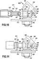
figure 10 est une vue en élévation d'un mode de réalisation du dispositif conforme à l'invention, la fiche étant représentée en coupe ; - les
figures 11 à 13 illustrent l'assemblage et le verrouillage de la fiche sur son socle ; - la
figure 14 est une vue de détail selon la flèche XIV de lafigure 10 ; - la
figure 14 est une vue de détail selon la flèche XIV de lafigure 10 ; - la
figure 15 est une vue de détail en perspective du socle et de la coiffe ; - la
figure 16 illustre un autre mode de réalisation d'un dispositif conforme à l'invention représenté de façon analogue à lafigure 10 ; - les
figures 17 à 19 illustrent le montage et le verrouillage du dispositif ; et - la
figure 20 est une vue de détail selon la flèche XX de lafigure 16 . - En se reportant aux
figures 1 à 3 , on distingue un dispositif de connexion 11 entre un câble électrique 12 et une structure conductrice 13, ici un conducteur plat, comme par exemple une barre faisant partie d'un circuit de retour de courant dans un aéronef. Le dispositif de connexion se compose d'un socle de raccordement 15 de type femelle, fixé à la structure conductrice 13 et une fiche 17 de type mâle, raccordée à une extrémité dudit câble 12. - Le terme "câble électrique" doit être compris au sens large, il s'agit en fait de tout conducteur électrique susceptible de faire partie d'un réseau électrique câblé.
- Le socle 15 est en métal à haute conductivité il comporte ici deux prolongements filetés 19 traversant deux trous 21 de la structure conductrice. Des écrous 22 engagés sur ces parties filetées viennent assurer à la fois le montage mécanique et le raccordement électrique entre le socle 15 et ladite structure conductrice 13. On pourrait prévoir un nombre différent de prolongements filetés pour la fixation.
- Par ailleurs, la fiche 17, également en métal à haute conductivité se prolonge par une douille 25 à paroi déformable constituant un fût à sertir. Cette douille comporte donc un trou borgne 27 et sa paroi est de ce fait suffisamment mince pour permettre son écrasement. Une extrémité conductrice du câble électrique est engagée dans ce trou borgne et est immobilisée par écrasement et déformation permanente de la paroi. La douille 25 comporte aussi un trou ou une fente de contrôle 29 débouchant dans le trou borgne au voisinage de son extrémité interne. Ce trou de contrôle permet de vérifier la bonne insertion du câble électrique 12 dans le trou borgne 27 juste avant le sertissage. Les marques de sertissage 31 sont visibles sur les
figures 1 et 3 , à titre d'illustration. - Le socle de raccordement 15 comporte un perçage 33 conformé et dimensionné pour accueillir, avec contact électrique, ladite fiche 17. Comme représenté la fiche 17 comporte deux parties 34a, 34b de diamètres différents et par conséquent le perçage 33 du socle 15 comprend deux trous alignés 35a, 35b de diamètres différents correspondants. L'extrémité de la fiche, de plus petit diamètre comporte une gorge 37. Le bout 38 de la fiche est chanfreiné jusqu'au bord de cette gorge. Par ailleurs, un ressort de verrouillage 40 est solidaire du socle de raccordement et comporte au moins une branche flexible susceptible de s'engager dans la gorge 37 lorsque la fiche est engagée dans le perçage 33. Le ressort est du type filaire en acier élastique.
- Plus précisément, le perçage 33 est traversant et présente donc un orifice d'entrée 42 par lequel la fiche est engagée et un orifice de sortie 44, de plus faible diamètre, par lequel le bout 38 de la fiche fait saillie, faisant également apparaître la gorge 37. La longueur de la fiche 17 et celle du perçage sont telles que la gorge 37 se situe au delà de l'orifice de sortie 44 du perçage 33 lorsque la fiche 17 est engagée dans celui-ci. Comme représenté, le ressort 40 est situé au voisinage de l'orifice de sortie 44 pour coopérer avec la gorge 37 de la fiche 17. Avantageusement, le ressort 40 a la forme d'une épingle approximativement en U, montée entre deux éléments en saillie 48, 49 du socle. Les branches de l'épingle comportent des parties courbes 50 en vis-à-vis, au voisinage de l'orifice de sortie et de part et d'autre de celui-ci. Ces parties courbes sont sur le trajet de la fiche et on comprend que celle-ci, grâce à son bout chanfreiné, écarte momentanément lesdites parties courbes 50 jusqu'à ce que celles-ci s'engagent dans la gorge 37. A partir de ce moment, la fiche 17 est immobilisée mécaniquement dans le socle.
- Cette configuration de verrouillage mécanique est favorable à une bonne étanchéité des zones de contact électrique entre la fiche 17 et le socle 15. En effet, le socle comporte en outre un joint étanchéité annulaire 53 entourant intérieurement l'orifice de sortie 44. Ce joint vient donc s'appliquer sur la surface cylindrique de la partie de plus faible diamètre de la fiche. De l'autre côté, le socle comporte un joint d'entrée 55 fixé extérieurement autour de l'orifice d'entrée. Avantageusement la fiche comporte un épaulement 56 venant prendre appui contre ce joint d'entrée 55. Comme mentionné précédent, la coopération entre le ressort 40 et la gorge 37 assure aussi une compression du joint d'entrée 55 entre le socle 15 et l'épaulement 56.
- Comme visible sur les dessins le perçage 33 renferme en outre deux bandes de contact 59 annulaire distantes l'une de l'autre. Ces bandes de contacts, en métal à très faible résistivité sont légèrement comprimés par la partie 34a de plus grand diamètre, de la fiche, ce qui améliore la qualité du contact électrique entre la fiche et le socle.
- Ainsi, lors de la mise en place de la fiche 17 une double étanchéité est réalisée qui préserve entièrement la zone de contact électrique entre la fiche et le socle. Ladite fiche se trouve axialement immobilisée sans jeu axial grâce au ressort de verrouillage 40 et à la compression du joint d'entrée 55.
- Dans le mode de réalisation des
figures 4 à 6 , les éléments analogues à ceux de l'exemple comparatif décrit ci-dessus portent les mêmes références numériques augmentées de 100. On distingue donc un dispositif de connexion 111 entre un câble électrique 112 et une structure conductrice 113 en forme de conducteur plat, à savoir une barre faisant partie d'un circuit de retour de courant dans un aéronef. Comme précédemment, le dispositif de connexion se compose d'un socle de raccordement 115 de type femelle, fixé à la structure conductrice 113 et une fiche 117 de type maie, raccordée à une extrémité du câble 112. - Le socle 115 est en métal à haute conductivité. Il comporte un seul prolongement fileté 119 traversant un trou 121 de la structure conductrice 113. Un écrou 122 engagé sur cette partie filetée assure le montage mécanique et le raccordement électrique entre le socle 115 et la structure conductrice 113. Il est à noter que le socle 115 peut être ici entièrement réalisé à partir d'une ébauche métallique cylindrique, par usinage, ce qui en réduit le coût. Une goupille 116 est insérée dans un logement du socle et vient se placer dans un perçage 118 réalisé dans la structure conductrice 113, pour éviter la rotation du socle.
- Par ailleurs, la fiche 117, également en métal à haute conductivité se prolonge par une douille 125 à paroi déformable constituant un fut à sertir, comme dans l'exemple précédent. Cette douille comporte donc un trou borgne 127 à paroi mince, pour permettre son écrasement. Une extrémité conductrice du câble électrique 112 est engagée dans ce trou avant écrasement et déformation permanente de la paroi. Comme précédemment, la douille 125 comporte un trou ou une fente de contrôle 129.
- Le socle de raccordement 115 comporte un perçage 133 conformé et dimensionné pour accueillir, avec contact électrique, la fiche 117. Contrairement au mode de réalisation précédent, la partie de la fiche 117 destinée à être engagée dans le perçage 133 a un diamètre constant. Le perçage 133, quant à lui, est un trou borgne de diamètre correspondant.
- Comme dans l'exemple comparatif précédent, la fiche comporte une gorge 137 mais celle-ci est pratiquée à distance de l'extrémité de la fiche 117. Le perçage 133 du socle présente donc seulement un orifice d'entrée 142 par lequel la fiche est engagée. Comme cela est visible sur les dessins, la longueur de la fiche et celle du perçage sont telles que ladite gorge 137 se situe en-deçà de l'orifice d'entrée 142 lorsque la fiche est engagée dans le perçage du socle. Comme précédemment, ce perçage 133 renferme deux bandes de contact 159 annulaires, distantes l'une de l'autre. On pourrait en prévoir un plus grand nombre. Ces bandes de contact sont en métal à très faible résistivité et sont comprimées par la fiche lorsque celle-ci est engagée dans le perçage. Ce dernier abrite aussi un joint annulaire 155, par exemple un joint torique placé dans un logement à l'intérieur du perçage, au voisinage de l'orifice d'entrée. Ce joint peut être surmoulé directement dans le socle. Il possède une ou plusieurs lèvres permettant d'assurer l'étanchéité lorsque la fiche est engagée.
- Le dispositif est équipé d'un ressort de verrouillage qui comporte une coiffe 140 conformée pour coopérer à la fois avec la gorge 137 et avec un rebord d'accrochage 141, saillant et annulaire, du socle. Dans l'exemple, ce rebord saillant est défini à l'extrémité du socle 115 opposée à celle qui porte le prolongement fileté 119.
- La coiffe comporte des doigts flexibles 161 et les extrémités de ces doigts sont munies de dentures 143, formant harpons coopérant avec ledit rebord saillant du socle.
- De plus, la coiffe 140 comporte une extension latérale 160, ici relativement flexible, dans laquelle est définie une ouverture latérale 162, conformée et dimensionnée pour coopérer avec la gorge 137 de la fiche. Plus précisément, dans cet exemple, l'ouverture 162 est une échancrure comprenant une partie droite 163 de montage, ouverte sur un bord de ladite extension latérale et une partie à contour arrondi 164 retenue avec jeu dans ladite gorge 137. La partie droite de montage débouche dans la partie à contour arrondi. La largeur de la partie droite 163 est très légèrement inférieure au diamètre du fond de la gorge 137, tandis que la partie à contour arrondi 164 est un peu plus large que le diamètre du fond de gorge. De cette façon, la coiffe est emboîtée à force sur la fiche et reste rattachée à celle-ci, avec un jeu entre l'extension latérale et le fond de la gorge.
- La coiffe comporte une protubérance élastique 166 prenant appui sur l'extrémité du socle 115. Cette protubérance élastique peut être réalisée par une déformation centrale de la coiffe ou par une patte obtenue par une découpe.
- Comme on le voit sur les
figures 7 à 9 , la coiffe 170 peut avoir une forme différente. Par exemple, le nombre de doigts flexibles 161a peut être plus réduit que dans le mode de réalisation précédent en sorte que la coiffe se résume ici à une sorte de fourche à trois branches prolongée par l'extension latérale 160a. - Selon une autre possibilité, l'ouverture pratiquée dans l'extension latérale 162a peut être un trou oblong 171 à contour fermé comprenant une partie circulaire 172 de diamètre sensiblement égal à celui de la fiche et une partie circulaire 173 de diamètre inférieur à celui de la fiche mais supérieur au diamètre du fond de ladite gorge. Ainsi, le montage de la coiffe 170 se fait en faisant coulisser la fiche dans la partie circulaire de plus grand diamètre du trou oblong 171 jusqu'à ce que l'extension latérale s'engage dans la gorge 137. Au moment du montage sur le socle, l'extension latérale bascule et se verrouille dans la gorge par engagement de la partie circulaire de plus faible diamètre. Ainsi, avantageusement, la coiffe devient imperdable.
- Comme représenté, la fiche 117 peut être allégée en pratiquant un trou borgne 175 à partir de son extrémité distale.
- On notera que le mode de réalisation des
figures 4 à 8 présente l'avantage d'une étanchéité plus fiable, plus simple et moins coûteuse, ne nécessitant qu'un seul joint. - D'autres modifications sont possibles, en particulier en ce qui concerne la structure du ressort de verrouillage. Par exemple, celui-ci peut être en deux parties, une coiffe du genre décrit ci-dessus et un moyen élastique logé au fond du trou borgne du socle pour repousser élastiquement la fiche et renforcer l'effet de verrouillage. Ceci permet aussi d'utiliser une coiffe sensiblement plus rigide et donc plus robuste.
- Les
figures 10 à 15 illustrent un autre mode de réalisation semblable à celui desfigures 4 à 9 . Les éléments analogues portent les mêmes références numériques augmentées encore de 100. On reconnaît donc un dispositif de connexion 211 comprenant un socle de raccordement 215 en métal à haute conductivité, fixé à une structure conductrice 213 par un prolongement fileté 219 et un écrou 222. Le dispositif comporte aussi une fiche 217 en métal à haute conductivité. Le socle comporte un perçage 233 pour accueillir la fiche 217. Le perçage 233 est ici parallèle à la structure conductrice 213. La fiche comporte une gorge 237 pratiquée à distance de son extrémité. Une fois la fiche engagée complètement dans le perçage 233, la gorge 237 se situe en-deçà de l'orifice d'entrée 242 du perçage 233. On reconnaît aussi les deux bandes de contact 259 annulaires en métal à très faible résistivité, agencées à l'intérieur du perçage 233. - Le dispositif comporte aussi une coiffe de verrouillage 240 conformée pour coopérer à la fois avec la gorge 237 et un rebord d'accrochage 241 du socle, constitué ici par le bord d'un trou 245 situé dans le prolongement axial du perçage 233, à l'opposé de l'orifice d'entrée 242. Plus précisément, la coiffe 240 est munie d'un doigt 246 comprenant un crochet 243 (en forme de cylindre biseauté) coopérant avec le bord du trou 245. La coiffe comporte comme précédemment une extension latérale 260 dans laquelle est définie une ouverture 262 conformée et dimensionnée pour coopérer avec la gorge 237 de ladite fiche. Comme visible sur la
figure 14 , l'ouverture 162 est une échancrure comprenant une partie de montage 263 évasée vers l'extérieur et ouverte sur un bord de l'extension latérale 260. Cette partie de montage débouche dans une partie à contour arrondi 264 qui vient s'encastrer dans la gorge 237. - De plus, la coiffe est munie de deux ergots 244 situés intérieurement en vis-à-vis sur des faces latérales parallèles 248. Ces ergots sont assujettis à se déplacer dans des rainures parallèles 247 opposées, rectilignes, ménagées dans le socle 215 en sorte que ladite coiffe 240 soit rattachée de façon imperdable audit socle.
- De plus, la fiche est munie d'un joint annulaire 255 situé près de la gorge 237 tandis que le socle comporte un épaulement interne 256 jouxtant l'orifice d'entrée 242.
- Dans l'exemple décrit, le trou 245 communique avec le perçage 233. Pour assurer l'étanchéité après montage, l'extrémité de la fiche porte un joint cylindrique 257 qui vient se comprimer au fond du perçage 233.
- Bien entendu, le socle peut être dépourvu de tronçons filetés 219 pour pouvoir être directement soudé sur la structure conductrice 213.
- Le fonctionnement est illustré par les
figures 11 à 13 . La coiffe étant basculée comme illustré sur lafigure 11 , l'orifice d'entrée 242 du perçage du socle est dégagé et on peut engager la fiche 217 dans le socle. Ensuite, comme représenté sur lafigure 12 , la coiffe 240 est basculée tout en étant maintenue au maximum au-dessus du socle de façon que l'ouverture 262 soit positionnée au-dessus de la gorge 237 de la fiche. Ceci n'est possible que lorsque la fiche 217 est complètement enfoncée dans le perçage 233 du socle et que le joint annulaire 255 n'est plus visible, étant en contact avec l'épaulement 256. Dans cette position, le joint 257 est également comprimé au fond du perçage du socle. En maintenant la fiche dans cette position, il suffit alors d'abaisser la coiffe 240 sur son socle comme représenté à lafigure 13 jusqu'à ce que l'extension latérale 260 se verrouille, après déformation élastique, sur le diamètre de la gorge 237 et que le crochet 243 coopère avec le bord 241 du trou 245. Une fenêtre de contrôle de positionnement constituée par un trou 258 de la coiffe arrive en regard d'une zone colorée 259 du socle donnant une indication visuelle de verrouillage à l'utilisateur. En fait, le dispositif comporte un trou 258 sur chaque face latérale 248 et le socle comporte deux zones colorées 259 correspondantes. - Les
figures 16 à 20 illustrent encore un autre mode de réalisation où les éléments de structure analogue portent les mêmes références numériques encore augmentées de 100. Ces éléments ne seront pas décrits à nouveau en détail. Dans ce mode de réalisation, le perçage 333 du socle destiné à accueillir la fiche 317 est perpendiculaire à un plan de montage de celui-ci, c'est-à-dire à la structure conductrice 313. Autrement dit, après montage, l'axe de la fiche 317 et celui du tronçon fileté 319 assurant la fixation du socle 315 sont confondus. - Dans ce mode de réalisation, le socle 315 comporte deux rebords d'accrochage 341 précités, situés latéralement. Il s'agit de trous 345 ménagés dans des nervures latérales 370 parallèles et opposées du socle. La coiffe comporte aussi deux doigts parallèles 372 comprenant des crochets 373 coopérant respectivement avec lesdits rebords d'accrochage 341, c'est-à-dire les trous 345, la coiffe 340 est pour le reste sensiblement identique à celle du mode de réalisation précédent. Elle comporte notamment bien entendu, pour la fonction imperdabilité, deux ergots 344 engagés dans deux rainures rectilignes 347 du socle, parallèles.
- Comme précédemment, la coiffe comporte au moins une fenêtre de contrôle de positionnement (un trou 358) et le socle comporte une zone colorée 359 en regard de laquelle vient se positionner ladite fenêtre lorsque la coiffe est correctement positionnée (voir
figure 19 ). Le montage illustré auxfigures 17 à 19 est comparable à celui du mode de réalisation précédent. La coiffe 340 étant relevée, on engage la fiche 317 dans le perçage 333 du socle jusqu'à ce que le joint annulaire 355 vienne en appui sur l'épaulement 356. Ensuite, la coiffe 340 est basculée jusqu'à ce que l'extension latérale 360 s'engage dans la gorge 337 de la fiche (figure 18 ). La coiffe est ensuite abaissée jusqu'à ce que l'extension 360 se verrouille, par déformation élastique, sur le diamètre de la gorge 337 et que les crochets 373 s'engagent dans les trous 345.
Claims (17)
- Dispositif de connexion entre un câble électrique et une structure conductrice, comportant un socle de raccordement (115,215,315) de type femelle, fixé à ladite structure conductrice et une fiche (117,217,317) de type mâle, ledit socle (115,215,315) comportant un perçage (133,233,333) conformé et dimensionné pour recevoir, avec contact électrique, ladite fiche, qui comporte une gorge (137,237,337) pratiquée à distance de l'extrémité de ladite fiche, un ressort de verrouillage (140,240,340) étant monté sur ledit socle de raccordement et comportant une branche flexible susceptible de s'engager dans ladite gorge (137,237,337) lorsque ladite fiche est engagée dans ledit perçage, qui présente un orifice d'entrée par lequel la fiche est engagée, le dispositif de connexion étant caractérisé en ce que ladite fiche est raccordée à une extrémité dudit câble (112,212,312), en ce que la longueur de la fiche et celle dudit perçage sont telles que ladite gorge (137,237,337) se situe en deçà de l'orifice d'entrée (142,242,342) lorsque la fiche est engagée dans ledit perçage et en ce que ledit ressort de verrouillage comporte une coiffe (140,240,340) conformée pour coopérer à la fois avec ladite gorge et avec un rebord d'accrochage (141,241,341) dudit socle.
- Dispositif selon la revendication 1, caractérisé en ce que ladite coiffe comporte une extension latérale (160,260,360) dans laquelle est définie une ouverture (162,262,362) conformée et dimensionnée pour coopérer avec la gorge (137,237,337) de ladite fiche.
- Dispositif selon la revendication 2, caractérisé en ce que ladite ouverture (162,262) est une échancrure comprenant une partie de montage (163,263), ouverte sur un bord de ladite extension latérale et débouchant dans une partie à contour arrondi (164,264), retenue dans ladite gorge.
- Dispositif selon la revendication 1, caractérisé en ce que ledit perçage (133) dudit socle (115) est un trou borgne.
- Dispositif selon la revendication 1 ou 4, caractérisé en ce que ladite coiffe (140) comporte des doigts flexibles (161) et en ce que les extrémités de ces doigts sont munies de dentures (143) formant harpons, coopérant avec ledit rebord d'accrochage (141).
- Dispositif selon la revendication 4, caractérisé en ce que ladite ouverture est un trou oblong (171) à contour fermé comprenant une partie circulaire (172) de diamètre sensiblement égal à celui de ladite fiche et une partie circulaire (173) de diamètre inférieur à celui de ladite fiche mais supérieur au diamètre du fond de ladite gorge.
- Dispositif selon l'une des revendications précédentes, caractérisé en ce que ladite coiffe comporte une protubérance élastique (166) prenant appui sur l'extrémité dudit socle.
- Dispositif selon l'une des revendications précédentes, caractérisé en ce que ledit perçage (133) renferme au moins une bande de contact (159) annulaire.
- Dispositif selon la revendication 8, caractérisé en ce que ledit perçage renferme plusieurs bandes de contact (159) distantes l'une de l'autre.
- Dispositif selon l'une des revendications précédentes, caractérisé en ce que ladite fiche (117) se prolonge par une douille (125) à paroi déformable constituant un fût à sertir, ledit câble électrique étant engagé dans un trou borgne (127) de cette douille et immobilisé par écrasement de sa paroi.
- Dispositif selon la revendication 10, caractérisé en ce que ladite douille (125) comporte un trou ou une fente de contrôle (129), débouchant dans ledit trou borgne.
- Dispositif selon l'une des revendications 1 à 3, caractérisé en ce que ladite coiffe est munie de deux ergots (244) assujettis à se déplacer dans des rainures parallèles (247) opposées dudit socle (240), en sorte que cette coiffe soit rattachée de façon imperdable audit socle.
- Dispositif selon la revendication 12, caractérisé en ce que ledit rebord d'accrochage (241) dudit socle est constitué par un trou (245) et en ce que ladite coiffe est munie d'un doigt (246) comprenant un crochet (243) coopérant avec le bord de ce trou.
- Dispositif selon la revendication 12 ou 13, caractérisé en ce que ladite fiche (217) est pourvue d'un joint annulaire (255) venant au contact d'un épaulement interne (256) dudit socle.
- Dispositif selon la revendication 14, caractérisé en ce que ledit trou (245) est débouchant dans le prolongement axial dudit perçage (233) et en ce que l'extrémité de ladite fiche porte un joint d'étanchéité (257).
- Dispositif selon la revendication 12, caractérisé en ce que le perçage (333) dudit socle destiné à accueillir la fiche (317)est perpendiculaire à un plan de montage de celui-ci, en ce que ledit socle comporte deux rebords d'accrochage (341) précités sous forme de trous (345) disposés latéralement et en ce que ladite coiffe (340) comporte deux doigts parallèles (372) comprenant des crochets coopérant respectivement avec lesdits rebords d'accrochage.
- Dispositif selon l'une des revendications 12 à 16, caractérisé en ce que ladite coiffe (240) comporte une fenêtre de contrôle de positionnement (258) et en ce que le socle comporte une zone colorée (259) en regard de laquelle vient se positionner ladite fenêtre lorsque la coiffe est correctement positionnée.
Applications Claiming Priority (3)
| Application Number | Priority Date | Filing Date | Title |
|---|---|---|---|
| FR0855657A FR2935202B1 (fr) | 2008-08-21 | 2008-08-21 | Dispositif de connexion entre un cable electrique et une structure conductrice, notamment pour circuit de retour de courant |
| FR0951196A FR2935200B1 (fr) | 2008-08-21 | 2009-02-25 | Dispositif de connexion entre un cable electrique et une structure conductrice, notamment pour circuit de retour de courant |
| PCT/FR2009/051602 WO2010020733A1 (fr) | 2008-08-21 | 2009-08-19 | Dispositif de connexion entre un cable electrique et une structure conductrice, notamment pour circuit de retour de courant. |
Publications (2)
| Publication Number | Publication Date |
|---|---|
| EP2324534A1 EP2324534A1 (fr) | 2011-05-25 |
| EP2324534B1 true EP2324534B1 (fr) | 2018-10-03 |
Family
ID=40469967
Family Applications (1)
| Application Number | Title | Priority Date | Filing Date |
|---|---|---|---|
| EP09740472.7A Active EP2324534B1 (fr) | 2008-08-21 | 2009-08-19 | Dispositif de connexion entre un cable electrique et une structure conductrice, notamment pour circuit de retour de courant. |
Country Status (7)
| Country | Link |
|---|---|
| US (1) | US8562371B2 (fr) |
| EP (1) | EP2324534B1 (fr) |
| CN (1) | CN102132459B (fr) |
| BR (1) | BRPI0917817B1 (fr) |
| CA (1) | CA2734695C (fr) |
| FR (2) | FR2935202B1 (fr) |
| WO (1) | WO2010020733A1 (fr) |
Families Citing this family (25)
| Publication number | Priority date | Publication date | Assignee | Title |
|---|---|---|---|---|
| DE202008014409U1 (de) * | 2008-10-29 | 2009-01-22 | Rosenberger Hochfrequenztechnik Gmbh & Co. Kg | HF-Winkelsteckverbinder |
| US8777647B2 (en) * | 2010-12-07 | 2014-07-15 | Delta Systems, Inc. | Connection system and method |
| CN102157819A (zh) * | 2010-12-28 | 2011-08-17 | 电光防爆科技(上海)有限公司 | 一种矿用防松脱接线装置 |
| US8851923B2 (en) | 2012-08-08 | 2014-10-07 | Emerson Electric Co. | Hermetically sealed terminal pins with holes for connecting to wires |
| FI124657B (en) * | 2012-12-31 | 2014-11-28 | Suunto Oy | Male connector for a telemetric receiver |
| AT513865B1 (de) * | 2013-02-01 | 2014-12-15 | Hirtenberger Automotive Safety | Aktuator |
| JP6480782B2 (ja) * | 2015-04-02 | 2019-03-13 | 株式会社マキタ | 電気機器 |
| FR3039009B1 (fr) * | 2015-07-16 | 2019-06-21 | Safran Electrical & Power | Dispositif de connexion electrique libre en translation avec protection contre les dommages par corps etrangers |
| JP6749698B2 (ja) * | 2015-09-04 | 2020-09-02 | 国立研究開発法人科学技術振興機構 | コネクタ基板、センサーシステム及びウェアラブルなセンサーシステム |
| EP3142207B1 (fr) * | 2015-09-11 | 2018-06-06 | NKT HV Cables GmbH | Dispositif de fixation pour une terminaison de câble et agencement comprenant ladite terminaison et ledit dispositif |
| DE102015016926A1 (de) * | 2015-12-24 | 2017-06-29 | Audi Ag | Elektrisches Verbindungselement |
| DE202016102669U1 (de) * | 2016-05-19 | 2017-08-22 | Würth Elektronik eiSos Gmbh & Co. KG | Kontaktierungsvorrichtung zur elektrischen Energieübertragung zu einer Leiterplatte |
| CN111725679B (zh) * | 2016-12-12 | 2021-12-10 | 上海电巴新能源科技有限公司 | 电连接装置 |
| CN107317296B (zh) * | 2017-08-09 | 2023-10-31 | 上海胜华电气股份有限公司 | 防火密水型预分支氧化镁电缆及其安装方法 |
| US10224698B1 (en) * | 2018-02-01 | 2019-03-05 | Etco, Inc. | Ignition wire spark plug connector |
| CN109687212A (zh) * | 2018-11-01 | 2019-04-26 | 深圳金信诺光电技术有限公司 | 一种90°出线的连接器 |
| CN112117588A (zh) * | 2020-09-29 | 2020-12-22 | 宣城立讯精密工业有限公司 | 一种密封圈及连接器 |
| CN113363739B (zh) * | 2021-05-25 | 2022-01-21 | 上海沪安电缆(无锡)有限公司 | 一种耐火绝缘电线电缆用接头及其使用方法 |
| EP4699192A1 (fr) * | 2023-04-17 | 2026-02-25 | Molex, LLC | Connecteur d'alimentation et procédé d'assemblage |
| USD1065091S1 (en) | 2023-05-05 | 2025-03-04 | Molex, Llc | Connector |
| USD1069716S1 (en) | 2023-05-05 | 2025-04-08 | Molex, Llc | Connector |
| USD1051061S1 (en) | 2023-05-05 | 2024-11-12 | Molex, Llc | Connector |
| USD1054992S1 (en) | 2023-05-05 | 2024-12-24 | Molex, Llc | Connector |
| TW202539095A (zh) * | 2024-03-18 | 2025-10-01 | 美商莫仕有限公司 | 電源連接器及組裝方法 |
| USD1125071S1 (en) | 2025-03-26 | 2026-05-05 | Molex, Llc | Connector |
Family Cites Families (29)
| Publication number | Priority date | Publication date | Assignee | Title |
|---|---|---|---|---|
| US2112680A (en) * | 1934-10-25 | 1938-03-29 | Gen Electric | Electric cord terminal |
| US2845291A (en) * | 1955-01-25 | 1958-07-29 | Gen Motors Corp | Retaining clip and assembly |
| JPS5540202U (fr) * | 1978-09-07 | 1980-03-14 | ||
| US4671591A (en) * | 1985-07-15 | 1987-06-09 | Physio-Control Corporation | Electrical connector |
| US4642859A (en) * | 1986-06-23 | 1987-02-17 | Chrysler Motors Corporation | Retaining clip |
| FR2627554B1 (fr) * | 1988-02-24 | 1990-08-10 | Rapid Sa | Dispositif de fixation perfectionnee formant pince et piece quelconque munie de ce dispositif |
| US4934366A (en) * | 1988-09-01 | 1990-06-19 | Siemens-Pacesetter, Inc. | Feedthrough connector for implantable medical device |
| DE8912039U1 (de) * | 1989-10-10 | 1991-02-07 | Robert Bosch Gmbh, 7000 Stuttgart | Verteilerläufer von Zündverteilern für Brennkraftmaschinen |
| FR2708150B1 (fr) * | 1993-07-19 | 1995-10-13 | Aerospatiale | Procédé de raccordement d'un câble électrique sur un élément d'extrémité et élément d'extrémité correspondant. |
| JPH07151132A (ja) * | 1993-11-30 | 1995-06-13 | Nippon Cable Syst Inc | クリップ付き軸端座金およびそれを用いた連結構造 |
| US5704100A (en) * | 1996-03-01 | 1998-01-06 | Federal-Hoffman, Inc. | Retaining clip system |
| JP3204918B2 (ja) * | 1996-04-08 | 2001-09-04 | 矢崎総業株式会社 | 蓄電池用端子構造 |
| DE29616933U1 (de) * | 1996-09-18 | 1998-01-22 | Siemens AG, 80333 München | Rastvorrichtung für ein geradlinig verschiebbares Bauteil |
| FR2756879A1 (fr) * | 1996-12-06 | 1998-06-12 | Adwest Oci Sa | Dispositif d'assemblage d'un corps de revolution sur un support, au moyen d'une agrafe |
| FR2764127B1 (fr) * | 1997-05-29 | 1999-09-03 | Air Lb Gmbh | Connecteur electrique a verrouillage |
| DE20007001U1 (de) * | 2000-04-15 | 2000-07-27 | Anton Hummel Verwaltungs Gmbh, 79183 Waldkirch | Stecker mit einer Hülse |
| US6490947B2 (en) * | 2000-06-23 | 2002-12-10 | Arnd Burger | Spring for attaching cable end fitting to bracket |
| DE10120226A1 (de) | 2001-04-25 | 2002-10-31 | Harting Automotive Gmbh & Co | Batterieklemme sowie Batterie |
| WO2003071635A1 (fr) * | 2002-02-15 | 2003-08-28 | Bal Seal Engineering Co., Inc. | Connecteur electrique medical implantable possedant une conductivite constante |
| DE10211634B4 (de) * | 2002-03-15 | 2005-08-04 | Gessmann Gmbh & Co. | Elektrische Steckverbindung |
| US6854946B2 (en) * | 2002-08-22 | 2005-02-15 | Allegiance Corporation | Flexible retainer clip |
| JP4484143B2 (ja) * | 2004-06-09 | 2010-06-16 | 日東工器株式会社 | プラグ/ソケットアセンブリ |
| DE202004015917U1 (de) * | 2004-10-13 | 2005-01-20 | Virchow, Florian | Kontaktierungselement zum elektrischen Kontaktieren von Bauteilen |
| DE102005037825B3 (de) * | 2005-08-08 | 2007-03-15 | Demag Cranes & Components Gmbh | Anordnung zur axialen Sicherung eines mit einer Nut versehenen Bolzens |
| US7581958B2 (en) * | 2006-02-03 | 2009-09-01 | Watlow Electric Manufacturing Company | High voltage heater termination |
| US7309247B1 (en) * | 2006-05-23 | 2007-12-18 | Micro-Coax | Cable interconnect |
| CN101682137B (zh) * | 2008-04-14 | 2012-07-18 | 三菱电机株式会社 | 触点 |
| FR2933244B1 (fr) * | 2008-06-25 | 2010-07-30 | Soc Dexploitation Des Procedes Marechal Sepm | Dispositif de connexion electrique securise |
| US7914347B2 (en) * | 2009-04-30 | 2011-03-29 | Corning Gilbert Inc. | Low resistance connector for printed circuit board |
-
2008
- 2008-08-21 FR FR0855657A patent/FR2935202B1/fr not_active Expired - Fee Related
-
2009
- 2009-02-25 FR FR0951196A patent/FR2935200B1/fr not_active Expired - Fee Related
- 2009-08-19 BR BRPI0917817-1A patent/BRPI0917817B1/pt not_active IP Right Cessation
- 2009-08-19 US US13/060,190 patent/US8562371B2/en active Active
- 2009-08-19 CA CA2734695A patent/CA2734695C/fr not_active Expired - Fee Related
- 2009-08-19 CN CN200980132541.7A patent/CN102132459B/zh active Active
- 2009-08-19 EP EP09740472.7A patent/EP2324534B1/fr active Active
- 2009-08-19 WO PCT/FR2009/051602 patent/WO2010020733A1/fr not_active Ceased
Non-Patent Citations (1)
| Title |
|---|
| None * |
Also Published As
| Publication number | Publication date |
|---|---|
| CA2734695A1 (fr) | 2010-02-25 |
| US20110237104A1 (en) | 2011-09-29 |
| FR2935202A1 (fr) | 2010-02-26 |
| CN102132459A (zh) | 2011-07-20 |
| FR2935202B1 (fr) | 2010-10-22 |
| CA2734695C (fr) | 2016-05-17 |
| US8562371B2 (en) | 2013-10-22 |
| FR2935200A1 (fr) | 2010-02-26 |
| FR2935200B1 (fr) | 2010-10-22 |
| BRPI0917817A2 (pt) | 2015-11-24 |
| BRPI0917817B1 (pt) | 2020-05-12 |
| EP2324534A1 (fr) | 2011-05-25 |
| WO2010020733A1 (fr) | 2010-02-25 |
| CN102132459B (zh) | 2014-11-19 |
Similar Documents
| Publication | Publication Date | Title |
|---|---|---|
| CA2734695C (fr) | Dispositif de connexion entre un cable electrique et une structure conductrice, notamment pour circuit de retour de courant | |
| EP3000155B1 (fr) | Appareillage électrique comportant un capteur de température logé dans un élément de support | |
| EP2273619B1 (fr) | Connecteur coaxial coudé et son procédé d'assemblage | |
| FR2758662A1 (fr) | Element de connecteur electrique coaxial a contact mobile et connecteur electrique coaxial comprenant un tel element de connecteur | |
| EP2477278B1 (fr) | Manchon pour connecteur électrique et son procédé d'assemblage | |
| FR2717623A1 (fr) | Connecteur pour câble coaxial. | |
| EP0312438B1 (fr) | Connecteur auto-dénudant pour conducteur électrique | |
| FR3025947A1 (fr) | Corps isolant pour connecteur debrochable | |
| FR2941819A1 (fr) | "dispositif pour liaison de masse" | |
| WO2016087799A1 (fr) | Element de connexion electrique a perçage de gaine isolante d'un fil electrique | |
| FR2932615A1 (fr) | Dispositif de connexion entre un cable electrique et une structure conductrice | |
| WO2017174939A1 (fr) | Connecteur électrique pour carénage d'aéronef | |
| EP1286427B1 (fr) | Bloc de jonction avec un bras de verrouillage pour connecteur enfichable | |
| EP0593336A1 (fr) | Attache amovible pour solidariser un support plat à un élément et connecteur la comportant | |
| FR3028356A1 (fr) | Borne de connexion electrique a vis imperdable | |
| EP1058344B1 (fr) | Appareillage de connexion mobile | |
| FR2881582A1 (fr) | Connecteur pour borne de batterie | |
| FR2872636A1 (fr) | Connecteur etanche | |
| FR2996687A1 (fr) | Contact de connecteur comportant une languette de verrouillage primaire et un dispositif de ressort de positionnement | |
| EP2381824B1 (fr) | Connecteur pour machine de preparation de boissons | |
| FR2627018A1 (fr) | Embout de raccordement electrique | |
| FR3051077A1 (fr) | Contact electrique femelle | |
| FR2618024A1 (fr) | Connecteur auto-denudant pour conducteur electrique | |
| FR2775131A1 (fr) | Borne de connexion electrique a cage | |
| CH626753A5 (fr) |
Legal Events
| Date | Code | Title | Description |
|---|---|---|---|
| PUAI | Public reference made under article 153(3) epc to a published international application that has entered the european phase |
Free format text: ORIGINAL CODE: 0009012 |
|
| 17P | Request for examination filed |
Effective date: 20110318 |
|
| AK | Designated contracting states |
Kind code of ref document: A1 Designated state(s): AT BE BG CH CY CZ DE DK EE ES FI FR GB GR HR HU IE IS IT LI LT LU LV MC MK MT NL NO PL PT RO SE SI SK SM TR |
|
| AX | Request for extension of the european patent |
Extension state: AL BA RS |
|
| 17Q | First examination report despatched |
Effective date: 20110728 |
|
| DAX | Request for extension of the european patent (deleted) | ||
| RIC1 | Information provided on ipc code assigned before grant |
Ipc: H01R 13/52 20060101ALN20170228BHEP Ipc: H02G 15/02 20060101ALN20170228BHEP Ipc: H01R 4/50 20060101ALN20170228BHEP Ipc: H01R 24/28 20110101ALI20170228BHEP Ipc: F16B 21/18 20060101ALN20170228BHEP Ipc: H01R 24/76 20110101ALI20170228BHEP Ipc: H01R 11/22 20060101AFI20170228BHEP Ipc: H01R 4/48 20060101ALI20170228BHEP |
|
| RIC1 | Information provided on ipc code assigned before grant |
Ipc: H01R 13/52 20060101ALN20170309BHEP Ipc: H01R 4/50 20060101ALN20170309BHEP Ipc: H02G 15/02 20060101ALN20170309BHEP Ipc: H01R 11/22 20060101AFI20170309BHEP Ipc: H01R 4/48 20060101ALI20170309BHEP Ipc: H01R 24/28 20110101ALI20170309BHEP Ipc: F16B 21/18 20060101ALN20170309BHEP Ipc: H01R 24/76 20110101ALI20170309BHEP |
|
| RAP1 | Party data changed (applicant data changed or rights of an application transferred) |
Owner name: SAFRAN ELECTRICAL & POWER |
|
| GRAP | Despatch of communication of intention to grant a patent |
Free format text: ORIGINAL CODE: EPIDOSNIGR1 |
|
| STAA | Information on the status of an ep patent application or granted ep patent |
Free format text: STATUS: GRANT OF PATENT IS INTENDED |
|
| RIC1 | Information provided on ipc code assigned before grant |
Ipc: H01R 13/52 20060101ALN20171026BHEP Ipc: H01R 4/48 20060101ALI20171026BHEP Ipc: F16B 21/18 20060101ALN20171026BHEP Ipc: H01R 24/28 20110101ALI20171026BHEP Ipc: H01R 4/50 20060101ALN20171026BHEP Ipc: H02G 15/02 20060101ALN20171026BHEP Ipc: H01R 11/22 20060101AFI20171026BHEP Ipc: H01R 24/76 20110101ALI20171026BHEP |
|
| INTG | Intention to grant announced |
Effective date: 20171127 |
|
| GRAS | Grant fee paid |
Free format text: ORIGINAL CODE: EPIDOSNIGR3 |
|
| GRAJ | Information related to disapproval of communication of intention to grant by the applicant or resumption of examination proceedings by the epo deleted |
Free format text: ORIGINAL CODE: EPIDOSDIGR1 |
|
| GRAL | Information related to payment of fee for publishing/printing deleted |
Free format text: ORIGINAL CODE: EPIDOSDIGR3 |
|
| STAA | Information on the status of an ep patent application or granted ep patent |
Free format text: STATUS: EXAMINATION IS IN PROGRESS |
|
| REG | Reference to a national code |
Ref country code: DE Ref legal event code: R079 Ref document number: 602009054864 Country of ref document: DE Free format text: PREVIOUS MAIN CLASS: H01R0004480000 Ipc: H01R0011220000 |
|
| GRAJ | Information related to disapproval of communication of intention to grant by the applicant or resumption of examination proceedings by the epo deleted |
Free format text: ORIGINAL CODE: EPIDOSDIGR1 |
|
| GRAP | Despatch of communication of intention to grant a patent |
Free format text: ORIGINAL CODE: EPIDOSNIGR1 |
|
| INTC | Intention to grant announced (deleted) | ||
| RIC1 | Information provided on ipc code assigned before grant |
Ipc: H01R 13/52 20060101ALN20180313BHEP Ipc: H01R 4/48 20060101ALI20180313BHEP Ipc: H01R 11/22 20060101AFI20180313BHEP Ipc: F16B 21/18 20060101ALN20180313BHEP Ipc: H02G 15/02 20060101ALN20180313BHEP Ipc: H01R 24/28 20110101ALI20180313BHEP Ipc: H01R 4/50 20060101ALN20180313BHEP Ipc: H01R 24/76 20110101ALI20180313BHEP |
|
| GRAJ | Information related to disapproval of communication of intention to grant by the applicant or resumption of examination proceedings by the epo deleted |
Free format text: ORIGINAL CODE: EPIDOSDIGR1 |
|
| STAA | Information on the status of an ep patent application or granted ep patent |
Free format text: STATUS: GRANT OF PATENT IS INTENDED |
|
| GRAP | Despatch of communication of intention to grant a patent |
Free format text: ORIGINAL CODE: EPIDOSNIGR1 |
|
| INTG | Intention to grant announced |
Effective date: 20180716 |
|
| GRAA | (expected) grant |
Free format text: ORIGINAL CODE: 0009210 |
|
| STAA | Information on the status of an ep patent application or granted ep patent |
Free format text: STATUS: THE PATENT HAS BEEN GRANTED |
|
| AK | Designated contracting states |
Kind code of ref document: B1 Designated state(s): AT BE BG CH CY CZ DE DK EE ES FI FR GB GR HR HU IE IS IT LI LT LU LV MC MK MT NL NO PL PT RO SE SI SK SM TR |
|
| REG | Reference to a national code |
Ref country code: GB Ref legal event code: FG4D Free format text: NOT ENGLISH |
|
| REG | Reference to a national code |
Ref country code: CH Ref legal event code: EP Ref country code: AT Ref legal event code: REF Ref document number: 1049645 Country of ref document: AT Kind code of ref document: T Effective date: 20181015 |
|
| REG | Reference to a national code |
Ref country code: DE Ref legal event code: R096 Ref document number: 602009054864 Country of ref document: DE Ref country code: IE Ref legal event code: FG4D Free format text: LANGUAGE OF EP DOCUMENT: FRENCH |
|
| REG | Reference to a national code |
Ref country code: NL Ref legal event code: MP Effective date: 20181003 |
|
| REG | Reference to a national code |
Ref country code: LT Ref legal event code: MG4D |
|
| REG | Reference to a national code |
Ref country code: AT Ref legal event code: MK05 Ref document number: 1049645 Country of ref document: AT Kind code of ref document: T Effective date: 20181003 |
|
| PG25 | Lapsed in a contracting state [announced via postgrant information from national office to epo] |
Ref country code: NL Free format text: LAPSE BECAUSE OF FAILURE TO SUBMIT A TRANSLATION OF THE DESCRIPTION OR TO PAY THE FEE WITHIN THE PRESCRIBED TIME-LIMIT Effective date: 20181003 |
|
| PG25 | Lapsed in a contracting state [announced via postgrant information from national office to epo] |
Ref country code: CZ Free format text: LAPSE BECAUSE OF FAILURE TO SUBMIT A TRANSLATION OF THE DESCRIPTION OR TO PAY THE FEE WITHIN THE PRESCRIBED TIME-LIMIT Effective date: 20181003 Ref country code: ES Free format text: LAPSE BECAUSE OF FAILURE TO SUBMIT A TRANSLATION OF THE DESCRIPTION OR TO PAY THE FEE WITHIN THE PRESCRIBED TIME-LIMIT Effective date: 20181003 Ref country code: NO Free format text: LAPSE BECAUSE OF FAILURE TO SUBMIT A TRANSLATION OF THE DESCRIPTION OR TO PAY THE FEE WITHIN THE PRESCRIBED TIME-LIMIT Effective date: 20190103 Ref country code: IS Free format text: LAPSE BECAUSE OF FAILURE TO SUBMIT A TRANSLATION OF THE DESCRIPTION OR TO PAY THE FEE WITHIN THE PRESCRIBED TIME-LIMIT Effective date: 20190203 Ref country code: HR Free format text: LAPSE BECAUSE OF FAILURE TO SUBMIT A TRANSLATION OF THE DESCRIPTION OR TO PAY THE FEE WITHIN THE PRESCRIBED TIME-LIMIT Effective date: 20181003 Ref country code: LT Free format text: LAPSE BECAUSE OF FAILURE TO SUBMIT A TRANSLATION OF THE DESCRIPTION OR TO PAY THE FEE WITHIN THE PRESCRIBED TIME-LIMIT Effective date: 20181003 Ref country code: BG Free format text: LAPSE BECAUSE OF FAILURE TO SUBMIT A TRANSLATION OF THE DESCRIPTION OR TO PAY THE FEE WITHIN THE PRESCRIBED TIME-LIMIT Effective date: 20190103 Ref country code: AT Free format text: LAPSE BECAUSE OF FAILURE TO SUBMIT A TRANSLATION OF THE DESCRIPTION OR TO PAY THE FEE WITHIN THE PRESCRIBED TIME-LIMIT Effective date: 20181003 Ref country code: PL Free format text: LAPSE BECAUSE OF FAILURE TO SUBMIT A TRANSLATION OF THE DESCRIPTION OR TO PAY THE FEE WITHIN THE PRESCRIBED TIME-LIMIT Effective date: 20181003 Ref country code: FI Free format text: LAPSE BECAUSE OF FAILURE TO SUBMIT A TRANSLATION OF THE DESCRIPTION OR TO PAY THE FEE WITHIN THE PRESCRIBED TIME-LIMIT Effective date: 20181003 Ref country code: LV Free format text: LAPSE BECAUSE OF FAILURE TO SUBMIT A TRANSLATION OF THE DESCRIPTION OR TO PAY THE FEE WITHIN THE PRESCRIBED TIME-LIMIT Effective date: 20181003 |
|
| PG25 | Lapsed in a contracting state [announced via postgrant information from national office to epo] |
Ref country code: SE Free format text: LAPSE BECAUSE OF FAILURE TO SUBMIT A TRANSLATION OF THE DESCRIPTION OR TO PAY THE FEE WITHIN THE PRESCRIBED TIME-LIMIT Effective date: 20181003 Ref country code: PT Free format text: LAPSE BECAUSE OF FAILURE TO SUBMIT A TRANSLATION OF THE DESCRIPTION OR TO PAY THE FEE WITHIN THE PRESCRIBED TIME-LIMIT Effective date: 20190203 Ref country code: GR Free format text: LAPSE BECAUSE OF FAILURE TO SUBMIT A TRANSLATION OF THE DESCRIPTION OR TO PAY THE FEE WITHIN THE PRESCRIBED TIME-LIMIT Effective date: 20190104 |
|
| REG | Reference to a national code |
Ref country code: DE Ref legal event code: R097 Ref document number: 602009054864 Country of ref document: DE |
|
| PG25 | Lapsed in a contracting state [announced via postgrant information from national office to epo] |
Ref country code: IT Free format text: LAPSE BECAUSE OF FAILURE TO SUBMIT A TRANSLATION OF THE DESCRIPTION OR TO PAY THE FEE WITHIN THE PRESCRIBED TIME-LIMIT Effective date: 20181003 Ref country code: DK Free format text: LAPSE BECAUSE OF FAILURE TO SUBMIT A TRANSLATION OF THE DESCRIPTION OR TO PAY THE FEE WITHIN THE PRESCRIBED TIME-LIMIT Effective date: 20181003 |
|
| PLBE | No opposition filed within time limit |
Free format text: ORIGINAL CODE: 0009261 |
|
| STAA | Information on the status of an ep patent application or granted ep patent |
Free format text: STATUS: NO OPPOSITION FILED WITHIN TIME LIMIT |
|
| PG25 | Lapsed in a contracting state [announced via postgrant information from national office to epo] |
Ref country code: SM Free format text: LAPSE BECAUSE OF FAILURE TO SUBMIT A TRANSLATION OF THE DESCRIPTION OR TO PAY THE FEE WITHIN THE PRESCRIBED TIME-LIMIT Effective date: 20181003 Ref country code: EE Free format text: LAPSE BECAUSE OF FAILURE TO SUBMIT A TRANSLATION OF THE DESCRIPTION OR TO PAY THE FEE WITHIN THE PRESCRIBED TIME-LIMIT Effective date: 20181003 Ref country code: RO Free format text: LAPSE BECAUSE OF FAILURE TO SUBMIT A TRANSLATION OF THE DESCRIPTION OR TO PAY THE FEE WITHIN THE PRESCRIBED TIME-LIMIT Effective date: 20181003 Ref country code: SK Free format text: LAPSE BECAUSE OF FAILURE TO SUBMIT A TRANSLATION OF THE DESCRIPTION OR TO PAY THE FEE WITHIN THE PRESCRIBED TIME-LIMIT Effective date: 20181003 |
|
| 26N | No opposition filed |
Effective date: 20190704 |
|
| PG25 | Lapsed in a contracting state [announced via postgrant information from national office to epo] |
Ref country code: SI Free format text: LAPSE BECAUSE OF FAILURE TO SUBMIT A TRANSLATION OF THE DESCRIPTION OR TO PAY THE FEE WITHIN THE PRESCRIBED TIME-LIMIT Effective date: 20181003 |
|
| PG25 | Lapsed in a contracting state [announced via postgrant information from national office to epo] |
Ref country code: TR Free format text: LAPSE BECAUSE OF FAILURE TO SUBMIT A TRANSLATION OF THE DESCRIPTION OR TO PAY THE FEE WITHIN THE PRESCRIBED TIME-LIMIT Effective date: 20181003 |
|
| PG25 | Lapsed in a contracting state [announced via postgrant information from national office to epo] |
Ref country code: LI Free format text: LAPSE BECAUSE OF NON-PAYMENT OF DUE FEES Effective date: 20190831 Ref country code: CH Free format text: LAPSE BECAUSE OF NON-PAYMENT OF DUE FEES Effective date: 20190831 Ref country code: LU Free format text: LAPSE BECAUSE OF NON-PAYMENT OF DUE FEES Effective date: 20190819 Ref country code: MC Free format text: LAPSE BECAUSE OF FAILURE TO SUBMIT A TRANSLATION OF THE DESCRIPTION OR TO PAY THE FEE WITHIN THE PRESCRIBED TIME-LIMIT Effective date: 20181003 |
|
| REG | Reference to a national code |
Ref country code: BE Ref legal event code: MM Effective date: 20190831 |
|
| PG25 | Lapsed in a contracting state [announced via postgrant information from national office to epo] |
Ref country code: IE Free format text: LAPSE BECAUSE OF NON-PAYMENT OF DUE FEES Effective date: 20190819 |
|
| PG25 | Lapsed in a contracting state [announced via postgrant information from national office to epo] |
Ref country code: BE Free format text: LAPSE BECAUSE OF NON-PAYMENT OF DUE FEES Effective date: 20190831 |
|
| PGFP | Annual fee paid to national office [announced via postgrant information from national office to epo] |
Ref country code: DE Payment date: 20200721 Year of fee payment: 12 Ref country code: GB Payment date: 20200722 Year of fee payment: 12 |
|
| PG25 | Lapsed in a contracting state [announced via postgrant information from national office to epo] |
Ref country code: CY Free format text: LAPSE BECAUSE OF FAILURE TO SUBMIT A TRANSLATION OF THE DESCRIPTION OR TO PAY THE FEE WITHIN THE PRESCRIBED TIME-LIMIT Effective date: 20181003 |
|
| PG25 | Lapsed in a contracting state [announced via postgrant information from national office to epo] |
Ref country code: MT Free format text: LAPSE BECAUSE OF FAILURE TO SUBMIT A TRANSLATION OF THE DESCRIPTION OR TO PAY THE FEE WITHIN THE PRESCRIBED TIME-LIMIT Effective date: 20181003 Ref country code: HU Free format text: LAPSE BECAUSE OF FAILURE TO SUBMIT A TRANSLATION OF THE DESCRIPTION OR TO PAY THE FEE WITHIN THE PRESCRIBED TIME-LIMIT; INVALID AB INITIO Effective date: 20090819 |
|
| REG | Reference to a national code |
Ref country code: DE Ref legal event code: R119 Ref document number: 602009054864 Country of ref document: DE |
|
| GBPC | Gb: european patent ceased through non-payment of renewal fee |
Effective date: 20210819 |
|
| PG25 | Lapsed in a contracting state [announced via postgrant information from national office to epo] |
Ref country code: MK Free format text: LAPSE BECAUSE OF FAILURE TO SUBMIT A TRANSLATION OF THE DESCRIPTION OR TO PAY THE FEE WITHIN THE PRESCRIBED TIME-LIMIT Effective date: 20181003 |
|
| PG25 | Lapsed in a contracting state [announced via postgrant information from national office to epo] |
Ref country code: GB Free format text: LAPSE BECAUSE OF NON-PAYMENT OF DUE FEES Effective date: 20210819 Ref country code: DE Free format text: LAPSE BECAUSE OF NON-PAYMENT OF DUE FEES Effective date: 20220301 |
|
| PGFP | Annual fee paid to national office [announced via postgrant information from national office to epo] |
Ref country code: FR Payment date: 20250827 Year of fee payment: 17 |