EP2322905A1 - Cellule de mesure de force destinée à la mesure de la force d'injection dans des moulages par injection - Google Patents
Cellule de mesure de force destinée à la mesure de la force d'injection dans des moulages par injection Download PDFInfo
- Publication number
- EP2322905A1 EP2322905A1 EP10014177A EP10014177A EP2322905A1 EP 2322905 A1 EP2322905 A1 EP 2322905A1 EP 10014177 A EP10014177 A EP 10014177A EP 10014177 A EP10014177 A EP 10014177A EP 2322905 A1 EP2322905 A1 EP 2322905A1
- Authority
- EP
- European Patent Office
- Prior art keywords
- sensor system
- deformation
- force
- measuring
- elements
- Prior art date
- Legal status (The legal status is an assumption and is not a legal conclusion. Google has not performed a legal analysis and makes no representation as to the accuracy of the status listed.)
- Withdrawn
Links
Images


Classifications
-
- B—PERFORMING OPERATIONS; TRANSPORTING
- B29—WORKING OF PLASTICS; WORKING OF SUBSTANCES IN A PLASTIC STATE IN GENERAL
- B29C—SHAPING OR JOINING OF PLASTICS; SHAPING OF MATERIAL IN A PLASTIC STATE, NOT OTHERWISE PROVIDED FOR; AFTER-TREATMENT OF THE SHAPED PRODUCTS, e.g. REPAIRING
- B29C45/00—Injection moulding, i.e. forcing the required volume of moulding material through a nozzle into a closed mould; Apparatus therefor
- B29C45/17—Component parts, details or accessories; Auxiliary operations
- B29C45/76—Measuring, controlling or regulating
- B29C45/77—Measuring, controlling or regulating of velocity or pressure of moulding material
-
- G—PHYSICS
- G01—MEASURING; TESTING
- G01L—MEASURING FORCE, STRESS, TORQUE, WORK, MECHANICAL POWER, MECHANICAL EFFICIENCY, OR FLUID PRESSURE
- G01L1/00—Measuring force or stress, in general
- G01L1/20—Measuring force or stress, in general by measuring variations in ohmic resistance of solid materials or of electrically-conductive fluids; by making use of electrokinetic cells, i.e. liquid-containing cells wherein an electrical potential is produced or varied upon the application of stress
- G01L1/22—Measuring force or stress, in general by measuring variations in ohmic resistance of solid materials or of electrically-conductive fluids; by making use of electrokinetic cells, i.e. liquid-containing cells wherein an electrical potential is produced or varied upon the application of stress using resistance strain gauges
- G01L1/2206—Special supports with preselected places to mount the resistance strain gauges; Mounting of supports
- G01L1/2218—Special supports with preselected places to mount the resistance strain gauges; Mounting of supports the supports being of the column type, e.g. cylindric, adapted for measuring a force along a single direction
- G01L1/2225—Special supports with preselected places to mount the resistance strain gauges; Mounting of supports the supports being of the column type, e.g. cylindric, adapted for measuring a force along a single direction the direction being perpendicular to the central axis
-
- G—PHYSICS
- G01—MEASURING; TESTING
- G01L—MEASURING FORCE, STRESS, TORQUE, WORK, MECHANICAL POWER, MECHANICAL EFFICIENCY, OR FLUID PRESSURE
- G01L1/00—Measuring force or stress, in general
- G01L1/20—Measuring force or stress, in general by measuring variations in ohmic resistance of solid materials or of electrically-conductive fluids; by making use of electrokinetic cells, i.e. liquid-containing cells wherein an electrical potential is produced or varied upon the application of stress
- G01L1/22—Measuring force or stress, in general by measuring variations in ohmic resistance of solid materials or of electrically-conductive fluids; by making use of electrokinetic cells, i.e. liquid-containing cells wherein an electrical potential is produced or varied upon the application of stress using resistance strain gauges
- G01L1/2206—Special supports with preselected places to mount the resistance strain gauges; Mounting of supports
- G01L1/2231—Special supports with preselected places to mount the resistance strain gauges; Mounting of supports the supports being disc- or ring-shaped, adapted for measuring a force along a single direction
- G01L1/2237—Special supports with preselected places to mount the resistance strain gauges; Mounting of supports the supports being disc- or ring-shaped, adapted for measuring a force along a single direction the direction being perpendicular to the central axis
-
- G—PHYSICS
- G01—MEASURING; TESTING
- G01L—MEASURING FORCE, STRESS, TORQUE, WORK, MECHANICAL POWER, MECHANICAL EFFICIENCY, OR FLUID PRESSURE
- G01L3/00—Measuring torque, work, mechanical power, or mechanical efficiency, in general
- G01L3/02—Rotary-transmission dynamometers
- G01L3/14—Rotary-transmission dynamometers wherein the torque-transmitting element is other than a torsionally-flexible shaft
- G01L3/1407—Rotary-transmission dynamometers wherein the torque-transmitting element is other than a torsionally-flexible shaft involving springs
- G01L3/1428—Rotary-transmission dynamometers wherein the torque-transmitting element is other than a torsionally-flexible shaft involving springs using electrical transducers
- G01L3/1457—Rotary-transmission dynamometers wherein the torque-transmitting element is other than a torsionally-flexible shaft involving springs using electrical transducers involving resistance strain gauges
-
- G—PHYSICS
- G01—MEASURING; TESTING
- G01L—MEASURING FORCE, STRESS, TORQUE, WORK, MECHANICAL POWER, MECHANICAL EFFICIENCY, OR FLUID PRESSURE
- G01L5/00—Apparatus for, or methods of, measuring force, work, mechanical power, or torque, specially adapted for specific purposes
- G01L5/16—Apparatus for, or methods of, measuring force, work, mechanical power, or torque, specially adapted for specific purposes for measuring several components of force
- G01L5/161—Apparatus for, or methods of, measuring force, work, mechanical power, or torque, specially adapted for specific purposes for measuring several components of force using variations in ohmic resistance
- G01L5/1627—Apparatus for, or methods of, measuring force, work, mechanical power, or torque, specially adapted for specific purposes for measuring several components of force using variations in ohmic resistance of strain gauges
-
- B—PERFORMING OPERATIONS; TRANSPORTING
- B29—WORKING OF PLASTICS; WORKING OF SUBSTANCES IN A PLASTIC STATE IN GENERAL
- B29C—SHAPING OR JOINING OF PLASTICS; SHAPING OF MATERIAL IN A PLASTIC STATE, NOT OTHERWISE PROVIDED FOR; AFTER-TREATMENT OF THE SHAPED PRODUCTS, e.g. REPAIRING
- B29C2945/00—Indexing scheme relating to injection moulding, i.e. forcing the required volume of moulding material through a nozzle into a closed mould
- B29C2945/76—Measuring, controlling or regulating
- B29C2945/76003—Measured parameter
- B29C2945/76013—Force
-
- B—PERFORMING OPERATIONS; TRANSPORTING
- B29—WORKING OF PLASTICS; WORKING OF SUBSTANCES IN A PLASTIC STATE IN GENERAL
- B29C—SHAPING OR JOINING OF PLASTICS; SHAPING OF MATERIAL IN A PLASTIC STATE, NOT OTHERWISE PROVIDED FOR; AFTER-TREATMENT OF THE SHAPED PRODUCTS, e.g. REPAIRING
- B29C2945/00—Indexing scheme relating to injection moulding, i.e. forcing the required volume of moulding material through a nozzle into a closed mould
- B29C2945/76—Measuring, controlling or regulating
- B29C2945/76177—Location of measurement
- B29C2945/7618—Injection unit
- B29C2945/76214—Injection unit drive means
-
- B—PERFORMING OPERATIONS; TRANSPORTING
- B29—WORKING OF PLASTICS; WORKING OF SUBSTANCES IN A PLASTIC STATE IN GENERAL
- B29C—SHAPING OR JOINING OF PLASTICS; SHAPING OF MATERIAL IN A PLASTIC STATE, NOT OTHERWISE PROVIDED FOR; AFTER-TREATMENT OF THE SHAPED PRODUCTS, e.g. REPAIRING
- B29C2945/00—Indexing scheme relating to injection moulding, i.e. forcing the required volume of moulding material through a nozzle into a closed mould
- B29C2945/76—Measuring, controlling or regulating
- B29C2945/76494—Controlled parameter
- B29C2945/76498—Pressure
-
- B—PERFORMING OPERATIONS; TRANSPORTING
- B29—WORKING OF PLASTICS; WORKING OF SUBSTANCES IN A PLASTIC STATE IN GENERAL
- B29C—SHAPING OR JOINING OF PLASTICS; SHAPING OF MATERIAL IN A PLASTIC STATE, NOT OTHERWISE PROVIDED FOR; AFTER-TREATMENT OF THE SHAPED PRODUCTS, e.g. REPAIRING
- B29C2945/00—Indexing scheme relating to injection moulding, i.e. forcing the required volume of moulding material through a nozzle into a closed mould
- B29C2945/76—Measuring, controlling or regulating
- B29C2945/76822—Phase or stage of control
- B29C2945/76859—Injection
Definitions
- the present invention relates to a method for mounting a force measuring device, which is particularly suitable for measuring the injection force during injection molding, as well as a device produced by the method.
- the injection pressure, under which a plasticized plastic or other injection molding material, such as liquid metal, is injected into an injection mold, are significant characteristics in injection molding and may be e.g. for all-electric injection molding machines are measured via the nozzle contact force.
- the measurement of these forces is usually carried out with a load cell, which is arranged in the injection unit of a machine on a rotating worm shaft rotationally symmetrical to the axis of rotation of the shaft, that by an axial feed movement of the worm shaft force applied by the injection pressure or the emphasis is built up, can be measured directly.
- Such generic force measuring cells generally comprise a rotationally symmetrical body with a force introduction part, a force extraction part and an intermediate deformation region. This deformation area is rotated in the form of a puncture in the body surface and receives a flat surface on the strain gauges (DMS) in pairs, with respect to the symmetry axis opposite, are glued precisely.
- a load cell further comprises an electronic circuit having a bridge amplifier with at least two input channels, with which the signals from at least one pair of strain gauges are added and amplified, with a mismatch in the readings of a pair of strain gauges being adjusted after assembly of the load cell with the circuit ,
- the size and the measuring range of a load cell are based on a respective customer-specific application and are determined in the present example of injection force measurement in injection molding essentially by the size of an injection unit.
- Force measuring cells for injection force measurement are manufactured in various sizes for measuring the respective nominal forces and are often installed on the customer's or user's side in a corresponding machine and put into operation.
- custom-made load cells designed to customer specifications may be required.
- the respective measuring range is determined by the geometry, in particular by the deformation range, while the strain gages and the associated electronics are constructed essentially identically for all types.
- the invention is therefore based on the object to provide a force measuring device, in particular for injection molding devices based on the DMS technology that can be used universally for different sizes of load cells and for different power ranges and reduces the production and transport costs.
- a sensor system according to the invention with strain gauges for axial and / or radial force measurement comprises at least one pair of deformation elements, wherein a respective deformation element comprises two mounting sections, a bending beam extending between the mounting sections, and at least one strain gauge element attached to the bending beam.
- strain gauges of the deformation elements are connected to electronics that are matched to the pair of deformation elements.
- the strain gauges may preferably be designed as strain gauges (DMS).
- strain gauges can also be applied to deformation elements, which are connected together only with a support member, So a bending beam with a loose end, which scans the movement.
- An advantage of the sensor system according to the invention is that the prefabricated deformation elements with strain gauges can be electronically balanced and ready for universal use for different sizes, force ranges and geometries of load cells.
- the adjustment can be made in the electronics, which preferably comprises at least one bridge amplifier, which is matched to the deformation elements and the strain gauges.
- the sensor system is manufactured separately from the measuring body of a load cell and can be mounted by the user without further adjustment on a specific measuring body.
- transport and assembly costs are significantly reduced.
- the deformation elements and the load cell are designed to be detachable from each other.
- screw connections on the holding sections of the deformation elements with the measuring body are suitable.
- a lockable clamping device It is also possible to use one end of the deformation element in a correspondingly shaped receptacle and to fix the other end by means of a screw.
- thermocouple provides that at least one of the deformation elements is mounted on the bending beam and connected to the electronics. With an analog and / or digital circuit within the electronics of the sensor system, a temperature-compensated ideal force measurement is thus possible.
- the present invention thus provides a sensor system that can be used for universal geometries of measuring bodies and therefore also for universal force measuring cell geometries.
- the electronics of the sensor system may comprise a computing device which stores a data record which is used for comparison with current measured values for generating forecasts.
- the data set may include a strain and / or strain model and / or may have been created from previously measured measurements.
- the computing device is adapted to current force measurements of the sensor system with the values of the Compare record. Based on the comparison, for example, a prediction of a material fatigue or a degradation of the sensor system can be created.
- a comparison between the data record and measured values can take place at predetermined time intervals or event-triggered.
- an algorithm can be implemented in the computing device which, using a bestfit algorithm, which is applied to stored measured values, a model of the relationship between the physical quantities or the associated measured variables, for example in the form of a bestfit data Context of the temporal change of the measured physical quantities created, and based on this model creates a forecast. This can be done according to an embodiment of the invention by comparison with a stored model.
- a selection device On the basis of predetermined criteria, this selection device decides whether a prognosis is generated on the basis of a comparison of current measured values with the stored data set or on the basis of a model created by the best-fit algorithm.
- the computing device is set up to perform an action depending on the comparison of the measured values with the prestored data set and / or the creation of a bestfit model.
- Such an action can be timed, approximately in predetermined time intervals or event-driven.
- a triggering of the action by an event is, for example, triggering by a prediction recognized, already existing or expected material fatigue.
- the action may be, for example, triggering a warning signal or sending communication data.
- Another possible action is a self-calibration, which is carried out, for example, timed at predetermined time intervals.
- a measuring body for an axial force measurement with a corresponding sensor system is detected by the present invention.
- the measuring body is constructed substantially rotationally symmetrical and has a deformation region which is formed annularly between a force introduction part and a force extraction part.
- Recesses are provided in the force introduction part and in the force release part, which are arranged on a straight connecting line relative to one another in such a way that the deformation elements of a pair of deformation elements can be mounted symmetrically to one another and flush on the surface of the deformation region.
- the measuring body according to the invention is thus suitable in a particularly advantageous manner for accurately fitting the sensor system.
- a respective pair of deformation elements of a sensor system by the user symmetrically to each other and flush mounted on the surface of the deformation region of the measuring body, without performing a further complex electronic balance.
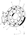
- FIG. 1 shows a known in the prior art, conventional load cell for measuring axially acting forces, which can be used for example for injection pressure measurement on the screw shaft of an injection molding machine.
- Such a load cell 10 of conventional design comprises a substantially rotationally symmetrical body 11, which consists for example of chromium-molybdenum steel and comprises a force introduction part 12, a force discharge part 13 and a deformation region 14.
- the deformation region is shown in the present figure in the form of a depression, for example by means of a lathe in the upper surface of the body 11th has been introduced.
- a second recess which is formed symmetrically to the first recess.
- the strain gauges 15a, 15b for axial force measurement are preferably glued in pairs to the surface of the deformation region 14 of a respective load cell.
- a strain gauge pair is in each case seconded symmetrically with respect to the symmetry axis of the body 11 in the deformation region 14.
- the load cell additionally includes electronics 16 which includes at least one bridge amplifier circuit, the inputs of each bridge circuit being electrically connected to the strain gauges. At an output of the electronics 16, application specific, e.g. a current or voltage signal is output.
- the bridge circuit allows a manual adjustment of a non-pairing in the electrical characteristic or an adjustment tolerance of the strain gauges 15a, 15b, wherein the adjustment is performed by the manufacturer.
- Holes 17 are provided in the force introduction part 12 and in the force discharge part 13, with which the load cell 10 is installed, for example, between a worm shaft of an injection molding machine and an associated drive unit for axial movement of the worm shaft, so that during injection molding the injection pressure acts on the worm shaft Force can be determined.
- a disadvantage of this concept of conventional load cells is that such a customer-configured load cell is manufactured as a unit supplied to the respective site to allow accurate adhesive mounting and electronic adjustment of the strain gages on the part of the manufacturer.
- FIG. 2 shows a force measuring cell 20 according to the invention, which is constructed essentially in two parts, from a sensor system on the one hand and a measuring body 21 on the other.
- the illustrated sensor system comprises two deformation elements 30a, 30b, which are combined with a prefabricated wiring 29 to a pair of deformation elements and are connected together with an electronics 26 by a cable not explicitly shown in the figure.
- the measuring body 21 again comprises a substantially rotationally symmetrical flange with a force introduction part 22, a force extraction part 23, and an annular deformation region 24.
- recesses 28 for receiving deformation elements 30a, 30b for mounting a sensor system are provided on the measuring body.
- the recesses 28 for receiving a pair of deformation elements are each arranged on a straight connecting line, which runs through the axis of symmetry of the measuring body 21, so that a symmetrically exact positioning of the deformation elements 30, 30a is possible.
- a deformation element 30a of a pair of deformation elements for the in Fig. 2 shown measuring body 21 is in the Fig. 3 shown.
- This deformation element 30a comprises two support portions 31, 32 and a bending beam 33, wherein on the extending between the support portions 31, 32 bending beam 33 two strain gauges 34, 35 are applied, which are designed for example as strain gauges.
- the main body of the deformation element 30a with two support portions 31, 32 and the bending beam is integrally formed, for example as a milled part.
- the deformation element on the measuring body 21 which has the shape of a flange, releasably secured. Suitable, for example, a screw.
- a deformation element 30a could also be equipped with only one strain gauge and be functional.
- a second deformation element 30b of a pair of deformation elements is constructed with respect to the definition of the respective support sections 31, 32 and the respective strain gauges 34, 35 mirror-symmetrical to the deformation element 30a, wherein the mirror symmetry only has to be taken into account in the electrical connection in the sensor system.
- the strain gauges 34, 35 of the strain elements are connected to the inputs of a bridge amplifier in the electronics 26, wherein an electrical mismatch of the strain gauges 34, 35 and a mechanical tolerance in the application of the strain gauges 34, 35 is adjusted to the bending beam 33 in the bridge amplifier.
- the electronic adjustment of the sensor system takes place before the installation of the deformation elements 30a, 30b in the measuring body 21 of a force measuring cell 20 according to the invention.
- thermocouple 36 may be provided on the respective bending beam 31 of one and / or both deformation elements of a pair of deformation elements.
- a measured temperature is forwarded in the form of an electrical signal to the electronics 26, whereby a Temperature compensation in the force measurement is possible.
- the temperature compensation can be done by means of an analog and / or a digital circuit unit.
- the mutually electronically compensated deformation elements 30a, 30b of a sensor system can be mounted by the user in the provided recesses 28 of a possibly already existing and application-specific dimensioned measuring body 21.
- the recesses 28 are introduced in the force introduction and force extraction parts 22, 23 of the measuring body 21 adjacent to the deformation region such that the deformation elements 30a, 30b of a sensor system can be arranged and mounted in a plane spanned by the surface of the deformation region.
Landscapes
- Physics & Mathematics (AREA)
- General Physics & Mathematics (AREA)
- Engineering & Computer Science (AREA)
- Manufacturing & Machinery (AREA)
- Mechanical Engineering (AREA)
- Force Measurement Appropriate To Specific Purposes (AREA)
- Injection Moulding Of Plastics Or The Like (AREA)
- Measurement Of Length, Angles, Or The Like Using Electric Or Magnetic Means (AREA)
Applications Claiming Priority (1)
| Application Number | Priority Date | Filing Date | Title |
|---|---|---|---|
| DE102009053043A DE102009053043A1 (de) | 2009-11-16 | 2009-11-16 | Kraftmesszelle zur Messung der Einspritzkraft beim Spritzgießen |
Publications (1)
| Publication Number | Publication Date |
|---|---|
| EP2322905A1 true EP2322905A1 (fr) | 2011-05-18 |
Family
ID=43707734
Family Applications (1)
| Application Number | Title | Priority Date | Filing Date |
|---|---|---|---|
| EP10014177A Withdrawn EP2322905A1 (fr) | 2009-11-16 | 2010-11-01 | Cellule de mesure de force destinée à la mesure de la force d'injection dans des moulages par injection |
Country Status (3)
| Country | Link |
|---|---|
| EP (1) | EP2322905A1 (fr) |
| CN (1) | CN102072793A (fr) |
| DE (1) | DE102009053043A1 (fr) |
Cited By (20)
| Publication number | Priority date | Publication date | Assignee | Title |
|---|---|---|---|---|
| JP2018091813A (ja) * | 2016-12-07 | 2018-06-14 | 日本電産コパル電子株式会社 | トルクセンサ |
| WO2018186008A1 (fr) * | 2017-04-07 | 2018-10-11 | 日本電産コパル電子株式会社 | Capteur de couple |
| WO2018189981A1 (fr) * | 2017-04-14 | 2018-10-18 | 日本電産コパル電子株式会社 | Capteur de force |
| CN108827506A (zh) * | 2018-08-15 | 2018-11-16 | 西南交通大学 | 一种高刚度二维力测量传感器 |
| WO2019171810A1 (fr) * | 2018-03-08 | 2019-09-12 | 日本電産コパル電子株式会社 | Capteur de couple |
| WO2019187706A1 (fr) * | 2018-03-29 | 2019-10-03 | 日本電産コパル電子株式会社 | Capteur de couple |
| WO2019187707A1 (fr) * | 2018-03-29 | 2019-10-03 | 日本電産コパル電子株式会社 | Capteur de couple |
| WO2019187705A1 (fr) * | 2018-03-29 | 2019-10-03 | 日本電産コパル電子株式会社 | Capteur de couple |
| JP2020148497A (ja) * | 2019-03-11 | 2020-09-17 | 日本電産コパル電子株式会社 | ロードセル |
| JP2020148498A (ja) * | 2019-03-11 | 2020-09-17 | 日本電産コパル電子株式会社 | ロードセル |
| JP2021063844A (ja) * | 2016-12-07 | 2021-04-22 | 日本電産コパル電子株式会社 | トルクセンサ |
| US20210325267A1 (en) * | 2020-04-16 | 2021-10-21 | MEAS France | Torque Sensor Device |
| EP3779390A4 (fr) * | 2018-04-09 | 2022-01-05 | Nidec Copal Electronics Corporation | Dispositif de fixation de capteur de contrainte et capteur de couple l'utilisant |
| JP2022010110A (ja) * | 2018-03-29 | 2022-01-14 | 日本電産コパル電子株式会社 | トルクセンサ |
| CN114364941A (zh) * | 2019-10-09 | 2022-04-15 | 日本电产科宝电子株式会社 | 应变传感器的固定装置和使用该固定装置的扭矩传感器 |
| WO2022149340A1 (fr) * | 2021-01-08 | 2022-07-14 | 日本電産コパル電子株式会社 | Capteur de couple |
| WO2022153974A1 (fr) * | 2021-01-12 | 2022-07-21 | ミネベアミツミ株式会社 | Transducteur de couple du type à plaque d'entraînement |
| EP3581908B1 (fr) * | 2017-02-13 | 2023-06-28 | Nidec Copal Electronics Corporation | Capteur de couple |
| EP4227656A1 (fr) * | 2022-02-14 | 2023-08-16 | TE Connectivity Sensors France | Système de détection de couple |
| EP4043848A4 (fr) * | 2019-10-09 | 2023-11-01 | Nidec Copal Electronics Corporation | Dispositif de fixation de capteur de contrainte et capteur de couple l'utilisant |
Families Citing this family (4)
| Publication number | Priority date | Publication date | Assignee | Title |
|---|---|---|---|---|
| CN108369146B (zh) * | 2015-10-28 | 2020-09-18 | 伊利诺斯工具制品有限公司 | 测力装置 |
| CN110341148B (zh) * | 2018-04-02 | 2022-09-23 | 诸暨市碧涵精工模塑有限公司 | 一种注塑机墙板挠度补偿机构 |
| TWI674959B (zh) * | 2018-11-30 | 2019-10-21 | 財團法人金屬工業研究發展中心 | 模具內之壓力與溫度的感測裝置 |
| CN111380637B (zh) * | 2018-12-29 | 2022-03-25 | 无锡华润华晶微电子有限公司 | 脱模力测试装置及其测试方法 |
Citations (6)
| Publication number | Priority date | Publication date | Assignee | Title |
|---|---|---|---|---|
| GB2096777A (en) * | 1981-04-13 | 1982-10-20 | Yamato Scale Co Ltd | Measuring components of force and moment |
| EP0331735A1 (fr) * | 1987-07-24 | 1989-09-13 | Fanuc Ltd. | Machine de moulage par injection comportant une fonction de detection de la pression de resine |
| EP0352788A2 (fr) * | 1988-07-28 | 1990-01-31 | Fraunhofer-Gesellschaft Zur Förderung Der Angewandten Forschung E.V. | Roue mesureuse |
| DE4208522A1 (de) * | 1992-03-18 | 1993-09-23 | Hottinger Messtechnik Baldwin | Drehmomentsensor |
| EP1344624A1 (fr) * | 2002-03-13 | 2003-09-17 | Demag Ergotech GmbH | Dispositif de mesure de pression pour une presse à injecter |
| US20060037409A1 (en) * | 2004-08-23 | 2006-02-23 | A&D Company, Limited | Rotary type component force measuring device |
Family Cites Families (3)
| Publication number | Priority date | Publication date | Assignee | Title |
|---|---|---|---|---|
| US3576128A (en) * | 1969-03-13 | 1971-04-27 | Blh Electronics | Half bridge moment desensitization of parallelogram-type beams |
| DD278644A1 (de) * | 1988-12-23 | 1990-05-09 | Univ Dresden Tech | Anordnung zur messung von spannungs- oder anderen kraeften |
| DE202009007478U1 (de) * | 2009-05-26 | 2009-09-03 | Elero Gmbh | Antriebsvorrichtung |
-
2009
- 2009-11-16 DE DE102009053043A patent/DE102009053043A1/de not_active Withdrawn
-
2010
- 2010-11-01 EP EP10014177A patent/EP2322905A1/fr not_active Withdrawn
- 2010-11-16 CN CN2010105466870A patent/CN102072793A/zh active Pending
Patent Citations (6)
| Publication number | Priority date | Publication date | Assignee | Title |
|---|---|---|---|---|
| GB2096777A (en) * | 1981-04-13 | 1982-10-20 | Yamato Scale Co Ltd | Measuring components of force and moment |
| EP0331735A1 (fr) * | 1987-07-24 | 1989-09-13 | Fanuc Ltd. | Machine de moulage par injection comportant une fonction de detection de la pression de resine |
| EP0352788A2 (fr) * | 1988-07-28 | 1990-01-31 | Fraunhofer-Gesellschaft Zur Förderung Der Angewandten Forschung E.V. | Roue mesureuse |
| DE4208522A1 (de) * | 1992-03-18 | 1993-09-23 | Hottinger Messtechnik Baldwin | Drehmomentsensor |
| EP1344624A1 (fr) * | 2002-03-13 | 2003-09-17 | Demag Ergotech GmbH | Dispositif de mesure de pression pour une presse à injecter |
| US20060037409A1 (en) * | 2004-08-23 | 2006-02-23 | A&D Company, Limited | Rotary type component force measuring device |
Cited By (30)
| Publication number | Priority date | Publication date | Assignee | Title |
|---|---|---|---|---|
| JP2021063844A (ja) * | 2016-12-07 | 2021-04-22 | 日本電産コパル電子株式会社 | トルクセンサ |
| US11085839B2 (en) | 2016-12-07 | 2021-08-10 | Nidec Copal Electronics Corporation | Torque sensor capable of independently setting the sensitivity and allowance torque of a strain sensor |
| JP2018091813A (ja) * | 2016-12-07 | 2018-06-14 | 日本電産コパル電子株式会社 | トルクセンサ |
| EP3581908B1 (fr) * | 2017-02-13 | 2023-06-28 | Nidec Copal Electronics Corporation | Capteur de couple |
| WO2018186008A1 (fr) * | 2017-04-07 | 2018-10-11 | 日本電産コパル電子株式会社 | Capteur de couple |
| WO2018189981A1 (fr) * | 2017-04-14 | 2018-10-18 | 日本電産コパル電子株式会社 | Capteur de force |
| JP2018179806A (ja) * | 2017-04-14 | 2018-11-15 | 日本電産コパル電子株式会社 | 力覚センサ |
| WO2019171810A1 (fr) * | 2018-03-08 | 2019-09-12 | 日本電産コパル電子株式会社 | Capteur de couple |
| WO2019187707A1 (fr) * | 2018-03-29 | 2019-10-03 | 日本電産コパル電子株式会社 | Capteur de couple |
| US11499879B2 (en) | 2018-03-29 | 2022-11-15 | Nidec Copal Electronics Corporation | Torque sensor having a strain sensor |
| JP2019174325A (ja) * | 2018-03-29 | 2019-10-10 | 日本電産コパル電子株式会社 | トルクセンサ |
| JP2019174326A (ja) * | 2018-03-29 | 2019-10-10 | 日本電産コパル電子株式会社 | トルクセンサ |
| TWI799515B (zh) * | 2018-03-29 | 2023-04-21 | 日商日本電產科寶電子股份有限公司 | 轉矩感測器 |
| JP2019174327A (ja) * | 2018-03-29 | 2019-10-10 | 日本電産コパル電子株式会社 | トルクセンサ |
| WO2019187705A1 (fr) * | 2018-03-29 | 2019-10-03 | 日本電産コパル電子株式会社 | Capteur de couple |
| WO2019187706A1 (fr) * | 2018-03-29 | 2019-10-03 | 日本電産コパル電子株式会社 | Capteur de couple |
| US11408786B2 (en) | 2018-03-29 | 2022-08-09 | Nidec Copal Electronics Corporation | Torque sensor |
| JP2022010110A (ja) * | 2018-03-29 | 2022-01-14 | 日本電産コパル電子株式会社 | トルクセンサ |
| EP3779390A4 (fr) * | 2018-04-09 | 2022-01-05 | Nidec Copal Electronics Corporation | Dispositif de fixation de capteur de contrainte et capteur de couple l'utilisant |
| US11333564B2 (en) | 2018-04-09 | 2022-05-17 | Nidec Copal Electronics Corporation | Strain sensor fixing device for a torque sensor to prevent sensor performance decrease |
| CN108827506A (zh) * | 2018-08-15 | 2018-11-16 | 西南交通大学 | 一种高刚度二维力测量传感器 |
| JP2020148498A (ja) * | 2019-03-11 | 2020-09-17 | 日本電産コパル電子株式会社 | ロードセル |
| JP2020148497A (ja) * | 2019-03-11 | 2020-09-17 | 日本電産コパル電子株式会社 | ロードセル |
| CN114364941A (zh) * | 2019-10-09 | 2022-04-15 | 日本电产科宝电子株式会社 | 应变传感器的固定装置和使用该固定装置的扭矩传感器 |
| EP4043848A4 (fr) * | 2019-10-09 | 2023-11-01 | Nidec Copal Electronics Corporation | Dispositif de fixation de capteur de contrainte et capteur de couple l'utilisant |
| EP4043849A4 (fr) * | 2019-10-09 | 2023-11-08 | Nidec Copal Electronics Corporation | Dispositif de fixation de capteur de contrainte et capteur de couple l'utilisant |
| US20210325267A1 (en) * | 2020-04-16 | 2021-10-21 | MEAS France | Torque Sensor Device |
| WO2022149340A1 (fr) * | 2021-01-08 | 2022-07-14 | 日本電産コパル電子株式会社 | Capteur de couple |
| WO2022153974A1 (fr) * | 2021-01-12 | 2022-07-21 | ミネベアミツミ株式会社 | Transducteur de couple du type à plaque d'entraînement |
| EP4227656A1 (fr) * | 2022-02-14 | 2023-08-16 | TE Connectivity Sensors France | Système de détection de couple |
Also Published As
| Publication number | Publication date |
|---|---|
| DE102009053043A1 (de) | 2011-05-19 |
| CN102072793A (zh) | 2011-05-25 |
Similar Documents
| Publication | Publication Date | Title |
|---|---|---|
| EP2322905A1 (fr) | Cellule de mesure de force destinée à la mesure de la force d'injection dans des moulages par injection | |
| EP0233176B1 (fr) | Sonde pour la mesure de grandeurs physiques et procede d'egalisation des mesures | |
| DE202016008595U1 (de) | Drehmomentsensorvorrichtung zum Erfassen von Drehmomenten | |
| EP0042371A1 (fr) | Détecteur destiné à la mesure de déformations sur des corps creux | |
| DE3213319A1 (de) | Einrichtung zum messen von kraft- und momentkomponenten in mehreren richtungen | |
| DE102012112947B3 (de) | Montageverfahren für einen Dehnmessstreifen | |
| WO2006005528A1 (fr) | Module de torsion destine a un dispositif de detection du moment de torsion et procede de fabrication d'une roue a rayons destinee a un module de torsion | |
| EP2534457A1 (fr) | Procédé et dispositif d'étalonnage automatique de capteurs d'allongement ou de force | |
| DE102013108097B4 (de) | Verfahren zur Fertigung eines Kraftmesskörpers | |
| CH685613A5 (de) | Verfahren und Vorrichtung zum Erfassen von Materialspannungen in Formteilen. | |
| DE102006006037B4 (de) | Motor mit rotatorischem und linearem Antrieb mit integrierter Axialkraftmessung | |
| DE102005024020B4 (de) | Vorrichtung zum Kalibrieren von Dehnungsmessschaltungen | |
| EP0682235B1 (fr) | Appareil et procédé pour calibrer une jauge d'un dispositif de mesure | |
| DE2928940A1 (de) | Verfahren und vorrichtung zum messen der schliess- und zuhaltekraft an druck- und spritzgiessmaschinen | |
| DE2814988C3 (de) | "Vorrichtung zur Erfassung einer zwischen zwei gegeneinander bewegbaren Maschinenteilen auftretenden,im wesentlichen axialen Kraft" | |
| EP2428787B1 (fr) | Procédé et dispositif de calibrage d'un amplificateur de charge d'une chaîne de mesure piézoélectrique | |
| EP1466157B1 (fr) | Dispositif de mesure de force a faible taux de vibrations dans des essais de traction dynamiques rapides sur des echantillons de materiaux | |
| DE10120982B4 (de) | Vorrichtung und Verfahren zum Kalibrieren von Dehnungsmessschaltungen | |
| EP3460442A1 (fr) | Dispositif de mesure de mouvement, machine et procédé d'étalonnage du dispositif de mesure de mouvement | |
| DE3504276C1 (de) | Wandler | |
| DE102017110511A1 (de) | Wägezelle und Förderbandwaage | |
| AT520716B1 (de) | Vorrichtung und verfahren zum vermessen von elektrischen maschinen | |
| EP2103410A1 (fr) | Machine de moulage par injection de matière plastique dotée d'un dispositif de mesure de la force d'injection | |
| DE3815566A1 (de) | Verfahren zur ermittlung mechanischer spannungszustaende in mit pressmasse zu umhuellenden oder umhuellten, elektrischen oder elektronischen bauteilen | |
| DE102022117755A1 (de) | Sensoreinheit zur Überwachung einer Kavität in einer Spritzgiessform |
Legal Events
| Date | Code | Title | Description |
|---|---|---|---|
| PUAI | Public reference made under article 153(3) epc to a published international application that has entered the european phase |
Free format text: ORIGINAL CODE: 0009012 |
|
| AK | Designated contracting states |
Kind code of ref document: A1 Designated state(s): AL AT BE BG CH CY CZ DE DK EE ES FI FR GB GR HR HU IE IS IT LI LT LU LV MC MK MT NL NO PL PT RO RS SE SI SK SM TR |
|
| AX | Request for extension of the european patent |
Extension state: BA ME |
|
| STAA | Information on the status of an ep patent application or granted ep patent |
Free format text: STATUS: THE APPLICATION IS DEEMED TO BE WITHDRAWN |
|
| 18D | Application deemed to be withdrawn |
Effective date: 20111119 |