EP2321263B1 - Reaktor mit titansilikat-rezyklierung - Google Patents
Reaktor mit titansilikat-rezyklierung Download PDFInfo
- Publication number
- EP2321263B1 EP2321263B1 EP09781839.7A EP09781839A EP2321263B1 EP 2321263 B1 EP2321263 B1 EP 2321263B1 EP 09781839 A EP09781839 A EP 09781839A EP 2321263 B1 EP2321263 B1 EP 2321263B1
- Authority
- EP
- European Patent Office
- Prior art keywords
- filter
- reaction
- reactor
- water
- titanium silicalite
- Prior art date
- Legal status (The legal status is an assumption and is not a legal conclusion. Google has not performed a legal analysis and makes no representation as to the accuracy of the status listed.)
- Active
Links
Images


Classifications
-
- C—CHEMISTRY; METALLURGY
- C07—ORGANIC CHEMISTRY
- C07C—ACYCLIC OR CARBOCYCLIC COMPOUNDS
- C07C249/00—Preparation of compounds containing nitrogen atoms doubly-bound to a carbon skeleton
- C07C249/04—Preparation of compounds containing nitrogen atoms doubly-bound to a carbon skeleton of oximes
-
- B—PERFORMING OPERATIONS; TRANSPORTING
- B01—PHYSICAL OR CHEMICAL PROCESSES OR APPARATUS IN GENERAL
- B01J—CHEMICAL OR PHYSICAL PROCESSES, e.g. CATALYSIS OR COLLOID CHEMISTRY; THEIR RELEVANT APPARATUS
- B01J8/00—Chemical or physical processes in general, conducted in the presence of fluids and solid particles; Apparatus for such processes
- B01J8/005—Separating solid material from the gas/liquid stream
- B01J8/006—Separating solid material from the gas/liquid stream by filtration
-
- B—PERFORMING OPERATIONS; TRANSPORTING
- B01—PHYSICAL OR CHEMICAL PROCESSES OR APPARATUS IN GENERAL
- B01J—CHEMICAL OR PHYSICAL PROCESSES, e.g. CATALYSIS OR COLLOID CHEMISTRY; THEIR RELEVANT APPARATUS
- B01J8/00—Chemical or physical processes in general, conducted in the presence of fluids and solid particles; Apparatus for such processes
- B01J8/008—Details of the reactor or of the particulate material; Processes to increase or to retard the rate of reaction
- B01J8/009—Membranes, e.g. feeding or removing reactants or products to or from the catalyst bed through a membrane
-
- B—PERFORMING OPERATIONS; TRANSPORTING
- B01—PHYSICAL OR CHEMICAL PROCESSES OR APPARATUS IN GENERAL
- B01J—CHEMICAL OR PHYSICAL PROCESSES, e.g. CATALYSIS OR COLLOID CHEMISTRY; THEIR RELEVANT APPARATUS
- B01J8/00—Chemical or physical processes in general, conducted in the presence of fluids and solid particles; Apparatus for such processes
- B01J8/18—Chemical or physical processes in general, conducted in the presence of fluids and solid particles; Apparatus for such processes with fluidised particles
- B01J8/20—Chemical or physical processes in general, conducted in the presence of fluids and solid particles; Apparatus for such processes with fluidised particles with liquid as a fluidising medium
-
- C—CHEMISTRY; METALLURGY
- C07—ORGANIC CHEMISTRY
- C07C—ACYCLIC OR CARBOCYCLIC COMPOUNDS
- C07C251/00—Compounds containing nitrogen atoms doubly-bound to a carbon skeleton
- C07C251/32—Oximes
- C07C251/34—Oximes with oxygen atoms of oxyimino groups bound to hydrogen atoms or to carbon atoms of unsubstituted hydrocarbon radicals
- C07C251/44—Oximes with oxygen atoms of oxyimino groups bound to hydrogen atoms or to carbon atoms of unsubstituted hydrocarbon radicals with the carbon atom of at least one of the oxyimino groups being part of a ring other than a six-membered aromatic ring
-
- B—PERFORMING OPERATIONS; TRANSPORTING
- B01—PHYSICAL OR CHEMICAL PROCESSES OR APPARATUS IN GENERAL
- B01J—CHEMICAL OR PHYSICAL PROCESSES, e.g. CATALYSIS OR COLLOID CHEMISTRY; THEIR RELEVANT APPARATUS
- B01J2208/00—Processes carried out in the presence of solid particles; Reactors therefor
- B01J2208/00796—Details of the reactor or of the particulate material
- B01J2208/00823—Mixing elements
- B01J2208/00858—Moving elements
- B01J2208/00867—Moving elements inside the bed, e.g. rotary mixer
-
- B—PERFORMING OPERATIONS; TRANSPORTING
- B01—PHYSICAL OR CHEMICAL PROCESSES OR APPARATUS IN GENERAL
- B01J—CHEMICAL OR PHYSICAL PROCESSES, e.g. CATALYSIS OR COLLOID CHEMISTRY; THEIR RELEVANT APPARATUS
- B01J2219/00—Chemical, physical or physico-chemical processes in general; Their relevant apparatus
- B01J2219/00002—Chemical plants
- B01J2219/00027—Process aspects
- B01J2219/0004—Processes in series
-
- B—PERFORMING OPERATIONS; TRANSPORTING
- B01—PHYSICAL OR CHEMICAL PROCESSES OR APPARATUS IN GENERAL
- B01J—CHEMICAL OR PHYSICAL PROCESSES, e.g. CATALYSIS OR COLLOID CHEMISTRY; THEIR RELEVANT APPARATUS
- B01J29/00—Catalysts comprising molecular sieves
- B01J29/89—Silicates, aluminosilicates or borosilicates of titanium, zirconium or hafnium
-
- Y—GENERAL TAGGING OF NEW TECHNOLOGICAL DEVELOPMENTS; GENERAL TAGGING OF CROSS-SECTIONAL TECHNOLOGIES SPANNING OVER SEVERAL SECTIONS OF THE IPC; TECHNICAL SUBJECTS COVERED BY FORMER USPC CROSS-REFERENCE ART COLLECTIONS [XRACs] AND DIGESTS
- Y02—TECHNOLOGIES OR APPLICATIONS FOR MITIGATION OR ADAPTATION AGAINST CLIMATE CHANGE
- Y02P—CLIMATE CHANGE MITIGATION TECHNOLOGIES IN THE PRODUCTION OR PROCESSING OF GOODS
- Y02P20/00—Technologies relating to chemical industry
- Y02P20/50—Improvements relating to the production of bulk chemicals
- Y02P20/584—Recycling of catalysts
Definitions
- the present invention relates to a plant for carrying out chemical reactions with at least one reactor whose reaction space contains hydrogen peroxide and titanium silicalite.
- a system from the EP 1 316 545 B1
- the invention relates to a particular use of this system and a possible thanks to the system method for carrying out a reaction.
- the said titanium silicalite is a catalyst based on titanium, silicon and oxygen; preferably in zeolitic structure.
- Such catalysts are available under the product name "TS-1" from Evonik Degussa GmbH.
- the SiO 2 content contained in the titanium silicalite is soluble in the system. Therefore, the catalyst is depleted by unsaturated SiO 2 streams to SiO 2, so that arise 2 particles in the reaction space insoluble, inert, nanoscale TiO. These tiny ceramic particles are dispersed in water - which is formed, inter alia, by reaction from H 2 O 2 and must be removed from the reaction - discharged from the reactor and load because of their small size downstream systems of wastewater treatment. An effective filtering off of the catalyst residues is absolutely necessary.
- Catalyst solutions are often deposited with classical separation apparatus such as filters, centrifuges or hydrocyclones. In the present case, however, such processes do not lead to acceptable catalyst losses in the retentate or in the clear flow due to the nanoscale portion of active catalyst. In addition, there is the discontinuous nature of these processes, which can only be incorporated into a continuous reaction regime with the appropriate effort.
- EP-A-1468986 discloses a batch process for the production of cyclohexanone oxime by ammoximation wherein the catalyst is recycled by filtration and added to the reaction mixture.
- the present invention has the object, a system of the type mentioned in such a way that a continuous separation and recycling of the active catalyst in the reaction chamber with a long filter life is possible.
- the present invention is based on the finding that with the aid of the metering of a solid silicon sacrificial system it is possible to effectively stop the dissolution process of the catalyst at the level of the nanoscale catalyst particles, to prevent the formation of inert TiO 2 , the formation of irreversible cover layers To effectively prevent filtration membranes and thus ultimately increase the filter life.
- the addition of the solid Si sacrificial system allows the effective implementation of the reaction in the presence of titanium silicalite and hydrogen peroxide on the system according to the invention, in which the deposition of the catalyst and / or its residues by means of a filter, which with the water discharge line or with the return line with connected to the reaction space, thus allowing a recycle of the washed out with the excess water of reaction titanium silicalite.
- the said water is usually not pure H 2 O, but an aqueous phase of the reaction containing dissolved, dispersed or in particular suspended components.
- the term "water removal line” is therefore generally understood as the controlled material flow of the aqueous reaction phase in the direction of the filter. In fact, it is not absolutely necessary to design the water discharge line as a pipeline. Instead, a plant according to the invention can form within its organs a defined flow profile which comprises a flow path along which the mass flow of the water of reaction proceeds. This will be explained later.
- the invention differs from that in US Pat. No. 7,408,080 B2 scholarly, liquid victim system.
- the problem of the sudden precipitation of silicon crystals from supersaturated solution does not occur in the use of the solid, since it always dissolves only in such a proportion in the system, as its current solubility allows.
- There is virtually a high-precision, self-regulating dosage of silicon instead which is not achievable with apparatus design for metering the addition of a liquid silicon source: Even if liquid silicon was added only dropwise, would result in the immediate vicinity of the drop in the reaction mixture, a local supersaturation with silicon that can cause a precipitation reaction.
- the addition of the solid significantly reduces the expenditure on equipment when improving the metering accuracy.
- Si sacrificial system is a variety of silicon-containing solids. Particularly preferred is the use of precipitated silica, since this - compared to the catalyst - is inexpensive and can therefore be sacrificed.
- the reaction space in which the reaction is carried out does not necessarily have to extend to a single reactor. It is conceivable to equip the plant with a reactor cascade, ie with a plurality of individual reactors connected in series, each successive reactor being fed from the overflow of its predecessor.
- the first reactor water removal line is then understood to be a flow path along the overflows through the secondary reactors to the filter.
- the removal of the reaction water regularly requires a prior separation of the aqueous phase.
- the phase separation can take place in the reaction space itself, for example by switching off the agitator, provided that the phases then settle from each other. If this is not the case or if continuous process management is desired, a liquid / liquid separator can be assigned to the reactor which separates the water to be taken off from the reaction space together with dissolved and / or dispersed components from other liquid components contained in the reaction space. The reaction and the phase separation then takes place in different organs of the plant.
- the water discharge line understood in this context as a flow path from the reactor into the separator and from there to the filter.
- the filter can be advantageously incorporated into the reactor.
- a pipe for the water outlet is then partially dispensable, instead, a section would run as a flow path through the reaction space itself, which costs are saved.
- the filter may then be designed, for example, as part of the reactor wall.
- a particularly advantageous embodiment of the invention provides to carry out the filter as a filter tube, which surrounds the existing in most reactors agitator like a coat. The flow through the filter is then maintained by the agitator. Such a constellation thus allows the saving of an additional pump.
- the filter is a membrane filter with a ceramic membrane, since such a separation unit is resistant to aqueous, ammoniacal, H 2 O 2 -containing solution at about 85 to 95 ° C, as in the ammoximation from the reaction space withdrawn by means of the water discharge line and passed through the filter.
- cross-flow membrane filters are suitable as filters, since on the one hand they are able to deposit the catalysts safely and on the other hand they achieve a high continuous filter performance and can thus be integrated into a flowing industrial process.
- the plant according to the invention is preferably used for carrying out a particular two-phase ammoximation.
- the advantages achieved according to the invention can also be utilized in other reactions whose system usually dissolves titanium silicalite.
- the silicon source is precipitated silica, a solid that is relatively inexpensive.
- the concentration of the silicon source is at least the concentration of the catalyst:
- the ratio of the mass of the silicon source to the mass of the titanium silicalite in the reaction is 1: 1. Best results are achieved when the ratio is about 3: 1, which is three times the concentration of silicon over the catalyst.
- the removal of the water and the recycling of the separated catalyst can be carried out periodically, namely after temporarily switching off the stirring system of the reactor, so that spatially separated phases develop in the reactor, which simplify the removal of the aqueous phase.
- continuous process management is more economical; This is achieved with the aid of a liquid / liquid separator, which separates the aqueous phase of the reaction outside the reactor.
- the process according to the invention is outstandingly suitable for carrying out alkaline reactions, in particular for carrying out a two-phase ammoximation.
- FIG. 2 shows as a measure of the filtration performance of the membrane the course of the permeate after addition of 1.5% of the solid "Sipernat 320" (a Evonik Degussa GmbH available precipitated silica) to 1.5% TS-1 (titanium silicalite) dispersion under otherwise identical conditions as with the FIG. 1 underlying experiment. It can be seen that the process according to the invention causes an asymptotic approach to a nearly constant base permeate flow, during which the flow through the membrane to be added quickly evaporates without addition of sipernate (cf. FIG. 1 ).
- sipernat 320 a Evonik Degussa GmbH available precipitated silica
- TS-1 titanium silicalite
- a first periodically operated plant is in FIG. 3 symbolically represented. it includes a reactor 1 in which - as in EP 1 316 545 B1 taught - a two-phase ammoximation is performed. In this process, two liquid phases are formed in the reaction space at reaction conditions (pressure: 4 to 6 bar, temperature: 95 to 105 ° C.), an organic phase O and an aqueous phase A.
- the organic phase O is formed from the starting component cyclodecanone (short: CDON) and the target component cyclododecanonoxime (in short: 0-xim) both dissolved in the organic solvent isopropylcyclohexane (called: Hydrocumol).
- the aqueous phase A contains dissolved ammonia (NH 3 ), hydrogen peroxide (H 2 O 2 ) and ammonium salts (NH 4 + x - ). Titanium silicalite (TS-1) and precipitated silicic acid (sipernate) are suspended in the liquid phase.
- the pH of the aqueous phase is about 9 to 11.
- aqueous phase Due to its high proportion of dispersed components, the aqueous phase has a pulpy consistency, it is called a slurry.
- Surfactants such as "Marlon PS 30" from Sasol Germany GmbH may be provided as phase mediators between W and A.
- the two phases O and A are not in the normal reaction mode - as in Fig. 3 shown - spatially separated, but with the help of an in Figure 3 Stirrer not shown mixed together.
- the agitator In order to remove the water formed during the reaction from the reactor, the agitator is temporarily switched off, so that the phases settle on each other as shown. Then, slurry is pumped out with the aid of a pump 2 along a water discharge line 3 from the reactor space and conveyed to a cross-flow membrane filter 4.
- the temperature of the aqueous phase A in the water discharge line 3 before the filter 4 is about 85 ° C to 95 ° C.
- the ceramic filter membrane of the cross-flow filter 4 separates the washed out with the water solids TS-1 and Sipernat from the aqueous phase.
- the retentate R containing TS-1 and sipernate is recycled as a concentrated slurry along a return line 5 into the reactor 1.
- the permeate P containing water, ammonia and ammonium salts passes on via a permeate 6 to a distiller 7. This wins in water concentrated ammonia back; the latter passes through an ammonia return 8 again in the reaction.
- the residual water with the ammonium salts dissolved therein leaves the plant through sewer 9.
- the agitator is turned on again and the reaction continues with mixed phases. The change of operating states occurs periodically. In order to run the process continuously, two reactors would have to be connected in parallel, one of which is always in reaction mode, while the other is recycling.
- FIG. 4 A higher degree of integration is achieved in FIG. 4 partial system shown.
- the filter 4 is here embedded directly in the wall of the reactor 1, which saves piping.
- a (very short) section of the water discharge line 3 runs as a flow path 30 within the part of the reactor space occupied by the aqueous phase A.
- the filter is designed as a cylindrical filter tube 40 surrounding the agitator 10 which is anyway required in the reactor 1.
- the agitator 10 rotating coaxially with the filter tube 40 generates an airfoil within the reactor space, which along a flow path 30 comprises a mass flow of the water of reaction through the membrane of the filter tube 40.
- the mass flow of the retentate R passes through the filter tube 40 directly back into the reaction space.
- the return line 5 thus corresponds to an unchanneled flow path.
- FIG. 7 illustrates the decrease in sales of CDON without the addition of a Si sacrificial system in comparison to a erfindunlicen system to which the Si sacrificial system sipernate was added.
Landscapes
- Chemical & Material Sciences (AREA)
- Organic Chemistry (AREA)
- Chemical Kinetics & Catalysis (AREA)
- Engineering & Computer Science (AREA)
- Combustion & Propulsion (AREA)
- Separation Using Semi-Permeable Membranes (AREA)
- Physical Or Chemical Processes And Apparatus (AREA)
- Low-Molecular Organic Synthesis Reactions Using Catalysts (AREA)
- Catalysts (AREA)
- Organic Low-Molecular-Weight Compounds And Preparation Thereof (AREA)
Description
- Die vorliegende Erfindung betrifft eine Anlage zur Durchführung chemischer Reaktionen mit mindestens einem Reaktor, dessen Reaktionsraum Wasserstoffperoxid und Titansilikalit enthält. Bekannt ist eine solche Anlage aus der
EP 1 316 545 B1 . Ferner betrifft die Erfindung eine besondere Verwendung dieser Anlage und ein dank der Anlage ermöglichtes Verfahren zur Durchführung einer Reaktion. - Zahlreiche industriell durchgeführte chemische Reaktionen finden in Gegenwart von Titansilikalit statt, welches dabei als Katalysator dient. Als Beispiel sei die Ammoximierung genannt, also das Herstellen von Oximen aus Ketonen oder Aldehyden. Hinsichtlich dieser Reaktion wird auf die
EP 1 316 545 B1 ebenso wie auf dieEP 1 191 017 B1 verwiesen, auf deren Offenbarungsgehalt hier vollständig Bezug genommen wird. - Bei dem genannten Titansilikalit handelt es sich um einen Katalysator auf Basis von Titan, Silizium und Sauerstoff; vorzugsweise in zeolithischer Struktur. Derartige Katalysatoren sind unter der Produktbezeichung "TS-1" bei der Evonik Degussa GmbH erhältlich.
- Unter den Reaktionsbedingungen der Ammoximierung ist der in dem Titansilikalit enthaltene SiO2-Anteil in dem System löslich. Deswegen wird der Katalysator durch ungesättigte SiO2-Ströme um SiO2 abgereichert, sodass im Reaktionsraum unlösliche, inerte, nanoskalige TiO2-Partikel entstehen. Diese keramischen Kleinstpartikel werden dispergiert in Wasser - welches unter Anderem durch Reaktion aus H2O2 entsteht und aus der Reaktion abgezogen werden muss - aus dem Reaktor ausgetragen und belasten aufgrund ihrer geringen Größe nachgeschaltete Anlagen der Abwasseraufbereitung. Eine wirksame Abfilterung der Katalysatorrückstände ist zwingend erforderlich.
- Katalysatorlösungen werden häufig mit klassischen Trennapparaten wie beispielsweise Filtern, Zentrifugen oder Hydrozyklonen abgeschieden. Im vorliegenden Fall führen solche Verfahren bedingt durch den nanoskaligen Anteil aktiven Katalysators jedoch nicht zu akzeptablen Katalysatorverlusten im Retentat bzw. im Klarlauf. Hinzu kommt der diskontinuierliche Charakter dieser Verfahren, die nur mit entsprechendem Aufwand in eine kontinuierliche Reaktionsführung eingegliedert werden können.
- Aus der
DE 32 45 318 C3 ist es bekannt, Katalysatordispensionen mit dem Querstromfiltrations-Verfahren abzutrennen und kontinuierlich in die Reaktion zurückzuführen. In Laborversuchen wurde jedoch festgestellt, dass sich die Querstrom-Filtration mit keramischen Ultrafiltrationsmembranen nicht ohne Weiteres mit einer Ammoximierung kombinieren lässt, da die dabei entstehenden nanoskaligen TiO2-Partikel nach kurzer Zeit Deckschichten auf der Ultrafiltrationsmembran bilden und zu einer irreversiblen Verblockung des Filters führen: -
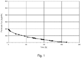
Figur 1 zeigt den Permeatflussabfall einer unter ammoniakalischen Bedingungen (5 %ige NH3-Lösung) kontinuierlich mit einer 1.5 %igen TS-1-Katalysatorslurry-Dispersion beschickten Keramik-Membran mit einer Trenngrenze von 0.05 µm. Bereits nach 150 Stunden war der Permeatfluss irreversibel auf weniger als 25 kg/m2h abgefallen. Dabei waren übliche Betriebsbedingungen für die Membran gewählt worden. Der Transmembrandruck lag bei 0.5 bar und die Überstromgeschwindigkeit bei etwa 4 m/s. Die Permeatausbeute lag unter 10 % bezogen auf die Einspeisung. Rasterelektronenaufnahmen zeigen, dass unter den Reaktionsbedingungen SiO2 aus dem Katalysator herausgelöst wird dabei gebildetes, nanoskaliges TiO2 die Membran zusetzt. - Die
US 7 408 080 B2 schlägt vor, die Auflösung des Titansilikalits bei der Ammoximierung durch Zugabe einer flüssigen Siliziumquelle zu unterbinden. Versuche zeigen jedoch, dass diese Maßnahme bei ungünstigen Reaktionsbedingungen zu einer schlagartigen Verblockung der Membran führen kann. Dies ist darauf zurückzuführen, dass die Zugabe der flüssigen Siliziumquelle das Reaktionsgemisch übersättigt, was wiederum eine plötzliche Kristallisation (Ausfallen) der Siliziumoxide hervorruft. Die ausgefallenen Kristallpartikel setzten die Filtermembran abrupt zu. -
EP-A-1468986 offenbart ein diskontinuierliches Verfahren zur Herstellung von Cyclohexanonoxim durch Ammoximierung, wobei der Katalysator durch Filtration rezykliert und zur Reaktionsmischung zugegeben wird. - In Hinblick auf diesen Stand der Technik liegt der vorliegenden Erfindung die Aufgabe zugrunde, eine Anlage der eingangs genannten Gattung so weiterzubilden, dass eine kontinuierliche Abtrennung und Rückführung des aktiven Katalysators in den Reaktionsraum mit einer langen Filterstandzeit möglich ist.
- Gelöst wird diese Aufgabe durch eine Anlage für die Durchführung chemischer Reaktionen, die mindestens einem Reaktor aufweist, dessen Reaktionsraum Wasserstoffperoxid und Titansilikalit enthält,
- wobei der Reaktionsraum eine feste Siliziumquelle enthält,
- wobei die Anlage eine Wasserabzugsleitung umfasst, die dafür eingerichtet ist, Wasser nebst darin gelöster und/oder dispergierter Komponenten aus dem Reaktionsraum abzuleiten,
- wobei die Wasserabzugsleitung zu einem die in dem Wasser gelösten und/oder dispergierten Komponenten abscheidendes Filter führt,
- wobei die Anlage eine Rückführleitung umfasst, welche dafür eingerichtet ist, mittels des Filters abgeschiedene Komponenten in den Reaktionsraum zurückzuführen, und
- dass dem Reaktor ein flüssig/flüssig-Abscheider zugeordnet ist, welcher das aus dem Reaktionsraum abzuleitende Wasser nebst darin gelöster
- und/oder dispergierter Komponenten von übrigen im Reaktionsraum befindlichen, flüssigen Komponenten abscheidet.
- Der vorliegenden Erfindung liegt die Erkenntnis zu Grunde, dass es mit Hilfe der Dosierung eines festen Silizium-Opfersystems gelingt, den Auflösungsprozess des Katalysators auf dem Niveau der nanoskaligen Katalysatorspartikeln wirksam zu stoppen, das Entstehen von inertem TiO2 zu vermeiden, die Bildung von irreversiblen Deckschichten auf Filtrationsmembranen wirksam vorzubeugen und damit letztendlich die Filterstandzeit zu erhöhen.
- Die Zugabe des festen Si-Opfersystems ermöglicht die effektive Durchführung der Reaktion unter Anwesenheit von Titansilikalit und Wasserstoffperoxid auf der erfindungsgemäßen Anlage, bei der die Abscheidung des Katalysators und/oder seiner Rückstände mittels eines Filter erfolgt, welches mit der Wasserabzugsleitung bzw. mit der Rücklaufleitung mit dem Reaktionsraum verbunden ist und so eine Rezyklierung des mit dem überschüssigen Reaktionswasser ausgeschwemmten Titansilikalits erlaubt. Bei dem genannten Wasser handelt es sich in der Regel nicht um reines H2O, sondern um eine wässrige Phase der Reaktion, die gelöste, dispergierte oder insbesondere suspendierte Komponenten enthält. Der Begriff "Wasserabzugsleitung" versteht sich deswegen allgemein als beherrschte Stoffströmung der wässrigen Reaktionsphase in Richtung des Filters. Es ist nämlich nicht zwingend erforderlich, die Wasserabzugsleitung als Rohrleitung auszuführen: Stattdessen kann eine erfindungsgemäße Anlage innerhalb ihrer Organe ein definiertes Strömungsprofil ausbilden, welche einen Strömungspfad umfasst, entlang dessen der Massestrom des Reaktionswassers verläuft. Dies soll später näher erläutert werden.
- Hinsichtlich der Verwendung der festen Siliziumquelle unterscheidet sich die Erfindung von dem in
US 7 408 080 B2 gelehrten, flüssigen Opfersystem. Das Problem des plötzlichen Ausfallens von Silizium-Kristallen aus übersättigter Lösung tritt bei der Verwendung des Feststoffes nicht auf, da sich dieser stets nur zu einem solchen Anteil im System löst, wie es dessen gegenwärtige Löslichkeit zulässt. Es findet quasi eine hochgenaue, selbstregulierende Dosierung des Siliziums statt, die mit apparativem Aufbau zur Dosierung der Zugabe einer flüssigen Siliziumquelle nicht erreichbar ist: Selbst wenn flüssiges Silizium nur tropfenweise zugegeben würde, entstünde in der unmittelbaren Umgebung des Tropfens im Reaktionsgemisch eine örtliche Übersättigung mit Silizium, die eine Fällreaktion verursachen kann. Die Zugabe des Feststoffes senkt den apparativen Dosierungs-Aufwand bei Verbesserung der Dosier-Genauigkeit deutlich. - Als Si-Opfersystem eignet sich eine Vielzahl von siliziumhaltigen Feststoffen. Besonders bevorzugt ist die Verwendung von gefällter Kieselsäure, da diese - verglichen mit dem Katalysator - preiswert ist und deswegen geopfert werden kann.
- Der Reaktionsraum, in welchem die Reaktion durchgeführt wird, muss sich nicht zwangsläufig auf einen einzelnen Reaktor erstrecken. Es ist denkbar die Anlage mit einer Reaktorkaskade auszurüsten, also mit einer Mehrzahl von hintereinander geschalteten Einzelreaktoren, wobei jeder Folgereaktor aus dem Überlauf seines Vorgängers gespeist wird. Die Wasserabzugsleitung für den ersten Reaktor versteht sich dann als ein Strömungspfad entlang der Überläufe durch die Folgereaktoren hindurch bis zu dem Filter.
- Soweit die Reaktion mehrphasig ist, erfordert das Abziehen des Reaktionswassers regelmäßig eine vorherige Trennung der wässrigen Phase. Die Phasentrennung kann im Reaktionsraum selbst stattfinden, beispielsweise durch Abschalten des Rührwerks, sofern sich die Phasen daraufhin voneinander absetzen. Ist dies nicht der Fall oder wird eine kontinuierliche Verfahrensführung angestrebt, kann dem Reaktor ein flüssig/flüssig-Abscheider zugeordnet werden, welcher das aus dem Reaktionsraum abzuleitende Wasser nebst darin gelöster und/oder dispergierter Komponenten von übrigen im Reaktionsraum enthaltenen, flüssigen Komponenten abscheidet. Die Reaktion und die Phasentrennung erfolgt dann in unterschiedlichen Organen der Anlage. Die Wasserabzugsleitung versteht sich in diesem Zusammenhang als ein Strömungspfad aus dem Reaktor in den Abscheider und von dort zum Filter.
- So die Phasentrennung im Reaktor selbst erfolgt, kann das Filter vorteilhafterweise in den Reaktor eingegliedert werden. Eine Rohrleitung für den Wasserabzug ist dann teilweise entbehrlich, stattdessen würde ein Abschnitt als Strömungspfad durch den Reaktionsraum selbst verlaufen, wodurch Kosten gespart werden. Das Filter kann dann beispielhaft als Teil der Reaktorwand ausgeführt sein.
- Eine besonders vorteilhafte Ausführungsform der Erfindung sieht vor, das Filter als Filterrohr auszuführen, welches das in den meisten Reaktoren vorhandene Rührwerk mantelartig umgibt. Der Fluss durch den Filter wird dann von dem Rührwerk aufrecht erhalten. Eine solche Konstellation erlaubt somit das Einsparen einer zusätzlichen Pumpe.
- Vorzugsweise handelt es sich bei dem Filter um ein Membran-Filter mit keramischer Membran, da eine solche Abtrenneinheit beständig ist gegen wässrige, ammoniakalische, H2O2-haltige Lösung bei etwa 85 bis 95 °C, wie sie bei der Ammoximierung aus dem Reaktionsraum mittels der Wasserabzugsleitung abgezogen und durch das Filter geführt wird.
- In besonderer Weise eigenen sich Querstrom-Membranfilter als Filter, da sie zum einen die Katalysatoren sicher abzuscheiden vermögen und zum anderen eine hohe kontinuierliche Filterleistung erreichen und sich so in einen fließenden Industrieprozess integrieren lassen.
- Vorzugsweise wird die erfindungsgemäße Anlage zur Durchführung einer insbesondere zweiphasigen Ammoximierung verwendet. Die erfindungsgemäß erzielten Vorteile lassen sich aber auch bei anderen Reaktionen nutzen, deren System Titansilikalit gewöhnlich löst.
- Die Durchführung einer unter Anwesenheit von Titansilikalit durchgeführten Reaktion geschieht auf der erfindungsgemäßen Anlage wie folgt:
- Wasser mit darin gelöstem und/oder dispergiertem Titansilikalit wird aus der Reaktion abgezogen,
- das abgezogene Titansilikalit wird über das Filter aus dem Wasser abgetrennt und in die Reaktion zurückgeführt,
- der Reaktion wird eine feste Siliziumquelle zugegeben.
- Bevorzugt handelt es sich bei der Siliziumquelle um gefällte Kieselsäure, einem Feststoff, der vergleichsweise preiswert ist.
- In einer besonders bevorzugten Ausführungsform der Erfindung beträgt die Konzentration der Siliziumquelle mindestens der Konzentration des Katalysators: Das Verhältnis der Masse der Siliziumquelle zu der Masse des Titansilikalits betrage in der Reaktion 1:1. Beste Ergebnisse werden erreicht, wenn das Verhältnis etwa 3:1 beträgt, also die dreifache Konzentration an Silizium gegenüber dem Katalysator.
- Das Abziehen des Wassers und das Rückführen des abgetrennten Katalysators kann periodisch erfolgen, nämlich nach vorübergehendem Abschalten der Rühranlage des Reaktors, sodass sich räumlich getrennte Phasen im Reaktor herausbilden, die das Abziehen der wässrigen Phase vereinfachen. Allerdings ist eine kontinuierliche Verfahrensführung wirtschaftlicher; diese gelingt mit Hilfe eines flüssig/flüssig-Abscheiders, welcher die wässrige Phase der Reaktion außerhalb des Reaktors abscheidet.
- Das erfindungsgemäße Verfahren eignet sich hervorragend zur Durchführung alkalischer Reaktionen, vor allem zur Durchführung einer zweiphasigen Ammoximierung.
- Die vorliegende Erfindung soll nun anhand eines bevorzugten Ausführungsbeispiels unter Zuhilfenahme der beiliegenden Abbildungen näher erläutert werden. Hierfür zeigen:
- Figur 1:
- Permeatflussabfall bei der TS-1-Katalysatorslurry-Abtrennung mit Keramik-Membran ohne Zugabe von Kieselsäure (Stand der Technik);
- Figur 2:
- wie
Figur 1 , jedoch mit Zugabe von Kieselsäure (erfindungsgemäß); - Figur 3:
- Schaltbild einer Anlage mit Einzelreaktor und separatem Filter (erste Ausführungsform);
- Figur 4:
- Schaltbild einer Anlage mit Einzelreaktor und in dessen Wand eingebetteten Filter (zweite Ausführungsform);
- Figur 5:
- Schaltbild einer Anlage mit Einzelreaktor und Filterrohr (dritte Ausführungsform);
- Figur 6:
- Schaltbild einer Anlage mit Reaktorkaskade und separatem Abscheider (vierte Ausführungsform);
- Figur 7:
- Veränderung des Umsatzes von CDON in der Anlage mit und ohne Zugabe von Kieselsäure.
- Der zu
Figur 1 gehörige Versuch wurde oben zur Erläuterung des der Erfindung zugrunde liegenden Problems beschrieben. -
Figur 2 zeigt demgegenüber als Maß für die Filtrationsleistung der Membran den Verlauf des Permeatflusses nach Zugabe von 1.5 % des Feststoffes "Sipernat 320" (eine der Evonik Degussa GmbH erhältliche gefällte Kieselsäure) zur 1.5 %igen TS-1 (Titansilikalit)-Dispersion unter ansonsten gleichen Bedingungen wie bei demFigur 1 zugrunde liegendem Versuch. Zu erkennen ist, dass die erfindungsgemäße Verfahrensführung eine asymptotische Annäherung an einen nahezu konstanten Sockel-Permeatfluss bewirkt, währenddessen ohne Sipernat-Zugabe der Fluss durch die sich zusetzende Membran rasch versiegt (vgl.Figur 1 ). - Die verlässliche Abscheideleistung des Filters erlaubt den Aufbau einer Anlage zur kontinuierlichen Durchführung einer zweiphasigen Ammoximierung. Gleichwohl sind auch periodisch betriebene Anlagen Gegenstand der Erfindung. Eine erste periodisch betriebene Anlage ist in
Figur 3 symbolisch dargestellt. Sie umfasst einen Reaktor 1, in welchem - wie inEP 1 316 545 B1 gelehrt - eine zweiphasige Ammoximierung durchgeführt wird. Bei diesem Verfahren bilden sich bei Reaktionsbedingungen (Druck: 4 bis 6 bar; Temperatur: 95 bis 105 °C) im Reaktionsraum zwei flüssige Phasen aus, eine organische Phase O und eine wässrige Phase A. Die organische Phase O wird gebildet aus der Ausgangskomponente Cyclodecanon (kurz: CDON) und der Zielkomponente Cyclododecanonoxim (kurz: 0-xim) beides gelöst in dem organischen Lösungsmittel Isopropylcyclohexan (genannt: Hydrocumol). Die wässrige Phase A enthält gelöst Ammoniak (NH3), Wasserstoffperoxid (H2O2) sowie Ammoniumsalze (NH4 +x-). Suspendiert sind in der flüssigen Phase Titansilikalit (TS-1) und mit der dreifachen Konzentration gefällte Kieselsäure (Sipernat). Der pH-Wert der wässrigen Phase beträgt etwa 9 bis 11. Aufgrund ihres hohen Anteils an dispergierten Anteilen hat die wässrige Phase eine breiige Konsistenz, man spricht von einem Slurry. Als Phasenvermittler zwischen W und A können Tenside wie "Marlon PS 30" der Sasol Germany GmbH vorgesehen sein. Die beiden Phasen O und A sind im normalen Reaktionsbetrieb nicht - wie inFig. 3 dargestellt - räumlich voneinander getrennt, sondern werden mit Hilfe eines inFig.3 nicht dargestellten Rührwerks miteinander vermischt. - Um das bei der Reaktion entstehende Wasser aus dem Reaktor zu entfernen wird das Rührwerk einstweilen abgeschaltet, sodass sich die Phasen wie dargestellt aufeinander absetzen. Sodann wird Slurry mit Hilfe einer Pumpe 2 entlang einer Wasserabzugsleitung 3 aus dem Reaktorraum abgepumpt und zu einem Querstrom-Membranfilter 4 gefördert. Die Temperatur der wässrigen Phase A in der Wasserabzugsleitung 3 beträgt vor dem Filter 4 etwa 85 °C bis 95 °C. Die keramische Filtermembran des Querstrom-Filters 4 scheidet die mit dem Wasser ausgeschwemmten Feststoffe TS-1 und Sipernat aus der wässrigen Phase ab. Das Retentat R enthaltend TS-1 und Sipernat wird als konzentrierter Slurry entlang einer Rückführleitung 5 in den Reaktor 1 rezykliert. Das Permeat P enthaltend Wasser, Ammoniak und Ammoniumsalze gelangt weiter über eine Permeatleitung 6 zu einem Destillator 7. Dieser gewinnt in Wasser konzentriert gelösten Ammoniak zurück; der letztere gelangt über eine Ammoniakrückleitung 8 erneut in die Reaktion. Das Restwasser mit den darin gelösten Ammoniumsalzen verlässt durch Abwasserleitung 9 die Anlage. Nach abgeschlossenem Rückgewinnungszyklus wird das Rührwerk wieder eingeschaltet und die Reaktion mit vermischten Phasen fortgeführt. Der Wechsel der Betriebszustände erfolgt periodisch. Um den Prozess kontinuierlich zu fahren, müssten zwei Reaktoren parallel geschaltet werden, von denen jeweils einer sich stets im Reaktionsbetrieb befindet, währenddessen der andere rezykliert.
- Einen höheren Intergrationsgrad erreicht die in
Figur 4 ausschnittsweise dargestellte Anlage. Das Filter 4 ist hier unmittelbar in die Wand des Reaktors 1 eingebettet, was Rohrleitung einspart. Ein (sehr kurzer) Abschnitt der Wasserabzugsleitung 3 verläuft als Strömungspfad 30 innerhalb des Teils des Reaktorraums, den die wässrige Phase A einnimmt. Ein Vorteil dieser Gestaltung besteht darin, dass in Ermangelung eines Rohrleitungsabschnittes zwischen Reaktionsraum und Filter praktisch kein Druckverlust auftritt; der Reaktionsdruck (4 bis 6 bar) lastet unmittelbar auf der Membran des Filters 4, was im Vergleich zu der inFigur 3 gezeigten Ausführungsform den Permeatfluss steigert. Rückführleitung 5 für Retentat R kann dann kurz ausfallen. - Bei der in
Figur 5 gezeigten Ausführungsform kann gegenüber der inFigur 4 gezeigten Anlage sogar die Pumpe eingespart werden: Dies gelingt dadurch, dass das Filter als ein das im Reaktor 1 ohnehin erforderliche Rührwerk 10 umgebendes, zylindrisches Filterrohr 40 ausgeführt ist. Das koaxial zum Filterrohr 40 rotierende Rührwerk 10 erzeugt innerhalb des Reaktorraums ein Strömungsprofil, welches entlang eines Strömungspfades 30 einen Massestrom des Reaktionswassers durch die Membran des Filterrohres 40 umfasst. Der Massenstrom des Retentats R tritt durch das Filterrohr 40 direkt in den Reaktionsraum zurück. Die Rückführleitung 5 entspricht damit einem unkanalisierten Strömungspfad. - Die vorstehend erläuterten Ausführungsbeispiele zeigen eine saubere Trennung zwischen organischer Phase O und wässriger Phase A innerhalb des Reaktionsraumes. Dies ist anzustrebsam, da das Filter 4 prinzipbedingt nicht zur Phasentrennung geeignet ist. Soweit die Reaktion nicht zwischen räumlich getrennten Phasen stattfindet, ist eine Phasentrennung erforderlich, etwa durch periodisches Ausschalten des Rührwerkes 10. Diese diskontinuierliche Verfahrensführung ist bei der zweiphasigen Ammoximierung unwirtschaftlich; es ist ein kontinuierlicher Betrieb anzustreben, welchen die in
Figur 6 gezeigte Anlage gestattet: - Der Reaktionsraum dieser Anlage ist auf drei Reaktoren 1 a, 1 b, 1 c verteilt, die hintereinander zu einer Kaskade verschaltet sind. Der sekundäre und der tertiäre Reaktor 1 b und 1 c werden jeweils aus dem Überlauf 11 des Vorgängers 1 a bzw. 1 b gespeist. Das Reaktortemperatur steigt innerhalb der Kaskade 1a, 1b, 1c von Reaktor zu Reaktor an, um die Löslichkeit des Oxims in dem Hydrocumol zu steigern. Die Phasen A und O sind innerhalb der Reaktoren 1a, 1b, 1c nicht räumlich voneinander getrennt, sondern stets ineinander vermengt. Um dennoch Wasser abziehen zu können, ist dem letzten Reaktor 1 c ein flüssig/flüssig-Abscheider 12 zugeordnet, welcher die Phasentrennung ausserhalb des Reaktionsraums vornimmt. Der Abscheider 12 wirkt stömungsberuhigend und weist in seinem unteren Bereich einen konischen Abschnitt auf, in welchem sich die schwerere wässrige Phase A absetzt. Von der Spitze des konischen Abschnittes aus ist die Wasserabzugsleitung 3 als Rohrleitung ausgeführt; ausgehend von der in der Kaskade räumlich verteilten Phase A bis zur genannten Spitze versteht sich die Wasserabzugsleitung als Strömungspfad 30 durch die Reaktoren 1a, 1 b, 1 c, entlang deren Überläufe 11 bis in den Abscheider 12. Rohrleitung 3 führt dann das Reaktionswasser A weiter über die Pumpe 2 zum Filter 4, wo das Retanat R für die Rezyklierung des Katalysators über die Rückführleitung 5 abgefiltert wird. Im Übrigen kann das Abfiltern des Retanats kann auch vor der Phasentrennung erfolgen, ein flüssig/flüssig-Abscheider ist dann in der Rückführleitung anzuordnen.
- Die soeben geschilderte Anlage erlaubt dank Zugabe der gefällten Kieselsäure eine die kontinuierliche Durchführung einer zweiphasigen Ammoximierung mit einem nahezu konstantem Umsatz von CDON:
- So wurde der Einfluss der Sipernat-Zugabe auf die Umsetzung von CDON mit NH3 (25 %ig) und H2O2 (50 %ig) an TS-1-Katalysatorslurry in einem System Wasser/Hydrocumol zum Oxim untersucht. Die Umsetzung des Speisestroms von 1.82 kg/h CDON erfolgte bei einem gestuft ansteigenden Temperaturprofil von 90 bis 105 °C in einer Kaskade aus drei Rührkesselreaktoren mit jeweils 10 I Reaktorrauminhalt, einer anschließenden Phasenseparation zur Produktabtrennung in einem separaten Abscheider und einer anschließenden Membranfiltration zur Abtrennung der wässrigen Phase unter Rückführung des Katalysatorslurrys in die Reaktorkaskade. Im System wurde im erfindungsgemäßen Beispiel eine TS1-Katalysatormasse von 1 kg neben 2 kg gefällter Kieselsäure vom Typ Sipernat vorgelegt.
- Im Gegenbeispiel wurde das Sipernat weggelassen. Aus dem System wurden mit dem Ammoniak- und dem Reaktionswasser bei einem Massenstrom von 2.56 kg/h jeweils 900 ppm SiO2 aus dem System ausgetragen. Durch diesen Austrag war der Katalysator ohne Opfersystem (Gegenbeispiel) nach 700 h soweit aufgelöst, dass der CDON-Umsatz von urspünglich 98-99 % auf 40 % gesunken ist. Mit der Zugabe einer Menge gefällter Kieselsäure, die größer ist als die aus dem System ausgetragene SiO2-Menge (erfindungsgemäßes Beispiel) bleibt der Katalysator TS-1 erhalten.
Figur 7 verdeutlicht die Abnahme des Umsatzes von CDON ohne Zugabe eines Si-Opfersystems im Vergleich zu einem erfindungemäßen System, dem das Si-Opfersystem Sipernat zugegeben wurde.
Claims (17)
- Anlage für die Durchführung chemischer Reaktionen, mit mindestens einem Reaktor (1), dessen Reaktionsraum Wasserstoffperoxid und Titansilikalit enthält,
dadurch gekennzeichnet,a) dass der Reaktionsraum eine feste Siliziumquelle enthält,b) dass die Anlage eine Wasserabzugsleitung (3) umfasst, die dafür eingerichtet ist, Wasser nebst darin gelöster und/oder dispergierter Komponenten aus dem Reaktionsraum abzuleiten,c) dass die Wasserabzugsleitung (3) zu einem die in dem Wasser gelösten und/oder dispergierten Komponenten abscheidendes Filter (4) führt,d) dass die Anlage eine Rückführleitung (5) umfasst, welche dafür eingerichtet ist, mittels des Filters (4) abgeschiedene Komponenten in den Reaktionsraum zurückzuführen unde) dass dem Reaktor (1) ein flüssig/flüssig-Abscheider (12) zugeordnet ist, welcher das aus dem Reaktionsraum abzuleitende Wasser nebst darin gelöster und/oder dispergierter Komponenten von übrigen im Reaktionsraum befindlichen, flüssigen Komponenten abscheidet. - Anlage nach Anspruch 1,
dadurch gekennzeichnet,
dass es sich bei der festen Siliziumquelle um gefällte Kieselsäure handelt. - Anlage nach Anspruch 1 oder 2,
gekennzeichnet durch
eine Vielzahl von zu einer Kaskade hintereinander geschalteten Reaktoren (1a, 1b, 1c). - Anlage nach einem der Ansprüche 1 bis 3,
dadurch gekennzeichnet,
dass das Filter (4) in den Reaktor (1) eingegliedert ist, wobei es sich bei der Wasserabzugsleitung zumindest abschnittsweise um einen Strömungspfad (30) innerhalb eines im Reaktor (1) gebildeten Strömungsprofils handelt. - Anlage nach Anspruch 4,
dadurch gekennzeichnet,
dass das Filter (4) in die Reaktorwand eingegliedert ist. - Anlage nach Anspruch 4,
wobei der Reaktor (1) mit einem Rührwerk (10) versehen ist,
dadurch gekennzeichnet,
dass das Filter (4) als ein das Rührwerk (10) umgebendes Filterrohr (40) ausgeführt ist. - Anlage nach einem der Ansprüche 1 bis 6,
dadurch gekennzeichnet,
dass es sich bei dem Filter (4) um ein Membran-Filter mit keramischer Membran handelt. - Anlage nach Anspruch 7,
dadurch gekennzeichnet,
dass es sich bei dem Filter (4) um ein Querstrom-Filter handelt. - Verwendung einer Anlage nach einem der Ansprüche 1 bis 8 zur Durchführung einer Ammoximierung, insbesondere einer zweiphasigen Ammoximierung.
- Verfahren zur Durchführung einer unter Anwesenheit von Titansilikalit durchgeführten Reaktion,
dadurch gekennzeichnet,
dass in kontinuierlicher Verfahrensführung Wasser mit darin gelöstem und/oder dispergiertem Titansilikalit aus der Reaktion abgezogen wird, dass das abgezogene Titansilikalit über ein Filter aus dem Wasser abgetrennt und in die Reaktion zurückgeführt wird, und dass der Reaktion eine feste Siliziumquelle zugegeben wird. - Verfahren nach Anspruch 10,
dadurch gekennzeichnet,
dass es sich bei der festen Siliziumquelle um gefällte Kieselsäure handet. - Verfahren nach Anspruch 10 oder 11,
dadurch gekennzeichnet,
dass das Verhältnis der Masse der Siliziumquelle zu der Masse des Titansilikalits 1:1 oder größer, vorzugsweise etwa 3:1 beträgt. - Verfahren nach einem der Ansprüche 10 bis 12,
dadurch gekennzeichnet,
dass das Abziehen des Wassers und das Rückführen des abgetrennten Titansilikalits kontinuierlich erfolgt. - Verfahren nach einem der Ansprüche 10 bis 12,
dadurch gekennzeichnet,
dass die Reaktion unter alkalischen Bedingungen durchgeführt wird. - Verfahren nach Anspruch 14,
dadurch gekennzeichnet,
dass es sich bei der Reaktion um eine Ammoximierung, insbesondere um eine zweiphasige Ammoximierung handelt. - Verwendung einer festen Siliciumquelle als Opfersystem zum Stoppen des Auflösungsprozesses eines Titansilikalit-Katalysators.
- Verwendung nach Anspruch 16,
dadurch gekennzeichnet,
dass es sich bei der festen Siliziumquelle um gefällte Kieselsäure handelt.
Applications Claiming Priority (2)
| Application Number | Priority Date | Filing Date | Title |
|---|---|---|---|
| DE102008041870A DE102008041870A1 (de) | 2008-09-08 | 2008-09-08 | Reaktor mit Titansilikat-Rezyklierung |
| PCT/EP2009/060536 WO2010026031A1 (de) | 2008-09-08 | 2009-08-14 | Reaktor mit titansilikat-rezyklierung |
Publications (2)
| Publication Number | Publication Date |
|---|---|
| EP2321263A1 EP2321263A1 (de) | 2011-05-18 |
| EP2321263B1 true EP2321263B1 (de) | 2017-06-07 |
Family
ID=41051733
Family Applications (1)
| Application Number | Title | Priority Date | Filing Date |
|---|---|---|---|
| EP09781839.7A Active EP2321263B1 (de) | 2008-09-08 | 2009-08-14 | Reaktor mit titansilikat-rezyklierung |
Country Status (7)
| Country | Link |
|---|---|
| US (1) | US8021632B2 (de) |
| EP (1) | EP2321263B1 (de) |
| JP (1) | JP5755140B2 (de) |
| CN (1) | CN101671219A (de) |
| DE (1) | DE102008041870A1 (de) |
| ES (1) | ES2635734T3 (de) |
| WO (1) | WO2010026031A1 (de) |
Families Citing this family (7)
| Publication number | Priority date | Publication date | Assignee | Title |
|---|---|---|---|---|
| DE102007054885A1 (de) * | 2007-11-15 | 2009-05-20 | Evonik Degussa Gmbh | Verfahren zur Fraktionierung oxidischer Nanopartikel durch Querstrom-Membranfiltration |
| DE102008043422B3 (de) | 2008-11-03 | 2010-01-07 | Evonik Degussa Gmbh | Verfahren zur Aufreinigung niedermolekularer Hydridosilane |
| DE102009001225A1 (de) | 2009-02-27 | 2010-09-02 | Evonik Oxeno Gmbh | Verfahren zur Anreicherung eines Homogenkatalysators aus einem Prozessstrom |
| DE102009001230A1 (de) | 2009-02-27 | 2010-09-02 | Evonik Oxeno Gmbh | Verfahren zur Abtrennung und teilweiser Rückführung von Übergangsmetallen bzw. deren katalytisch wirksamen Komplexverbindungen aus Prozessströmen |
| DE102009046910A1 (de) * | 2009-11-20 | 2011-05-26 | Evonik Degussa Gmbh | Verfahren zur Aufarbeitung eines Laurinlactam enthaltenen Stoffstroms für die Rückgewinnung aller enthaltene Wertstoffkomponenten durch Kombination von Kristallisation mit nachgeschalteter Destillation |
| DE102009047351A1 (de) | 2009-12-01 | 2011-06-09 | Evonik Goldschmidt Gmbh | Komposit-Siliconmembranen mit hoher Trennwirkung |
| CN111111592A (zh) * | 2020-01-03 | 2020-05-08 | 山东润德生物科技有限公司 | 一种基于陶瓷膜工艺的循环式分离系统 |
Family Cites Families (21)
| Publication number | Priority date | Publication date | Assignee | Title |
|---|---|---|---|---|
| DE3245318C3 (de) | 1982-12-08 | 1996-06-20 | Bayer Ag | Verfahren zur Durchführung von Druckreaktionen mit suspendierten Katalysatoren |
| IT1214622B (it) * | 1985-07-10 | 1990-01-18 | Montedipe Spa | Processo catalitico per laproduzione di cicloesanonossima. |
| JPH0610181B2 (ja) * | 1986-11-14 | 1994-02-09 | モンテデイペ・ソチエタ・ペル・アツイオニ | オキシム製造のための接触方法 |
| IT1244680B (it) * | 1991-01-23 | 1994-08-08 | Montedipe Srl | Processo a piu' stadi per l'ammossimazione in fase liquida dei composti carbonilici |
| JP3323213B2 (ja) * | 1991-09-10 | 2002-09-09 | 旭化成株式会社 | 懸濁触媒系の反応方法 |
| DE10047435A1 (de) | 2000-09-26 | 2002-04-11 | Degussa | Verfahren zur Herstellung von Oximen |
| DE10142620A1 (de) * | 2001-08-31 | 2003-03-20 | Degussa | Ammoximation von Ketonen und Aufarbeitung durch Pervaporation/Dampfpermeation |
| DE10142621A1 (de) * | 2001-08-31 | 2003-03-20 | Degussa | Aufarbeitung der Ammoximationsprodukte von Ketonen durch Flüssig-Flüssig-Extraktion in einem ternären Lösemittelsystem |
| DE10158352A1 (de) | 2001-11-28 | 2003-06-12 | Degussa | Zweiphasige Ammoximierung |
| US7408080B2 (en) | 2002-05-31 | 2008-08-05 | China Petroleum & Chemical Corporation | Process for ammoximation of carbonyl compounds |
| TWI324990B (en) * | 2002-06-28 | 2010-05-21 | Sumitomo Chemical Co | Method for producing cyclohexanone oxime |
| JP4633337B2 (ja) * | 2002-06-28 | 2011-02-16 | 住友化学株式会社 | シクロヘキサノンオキシムの製造方法 |
| DE10247495A1 (de) | 2002-10-11 | 2004-04-22 | Degussa Ag | Verfahren zur Epoxidierung cyclischer Alkene |
| DE10247496A1 (de) | 2002-10-11 | 2004-04-22 | Degussa Ag | Verwendung eines Absatzbeschleunigers bei der Epoxidierung |
| DE10260717A1 (de) | 2002-12-23 | 2004-07-01 | Degussa Ag | Verfahren zur Herstellung von Oximen |
| DE10301040B4 (de) | 2003-01-13 | 2005-07-21 | Stockhausen Gmbh | Aufreinigung eines Monomers durch Extraktion mit einem Phasenbildner und Kristallisation |
| JP4534428B2 (ja) * | 2003-04-09 | 2010-09-01 | 住友化学株式会社 | シクロヘキサノンオキシムの製造方法 |
| DE10344469A1 (de) | 2003-09-25 | 2005-04-14 | Degussa Ag | Coammoximierung von Ketonen |
| JP4639792B2 (ja) | 2004-12-22 | 2011-02-23 | 住友化学株式会社 | シクロヘキサノンオキシムの製造方法 |
| JP4548409B2 (ja) * | 2005-12-07 | 2010-09-22 | 住友化学株式会社 | シクロヘキサノンオキシムの製造方法 |
| CN200951385Y (zh) | 2006-08-31 | 2007-09-26 | 北京中天元环境工程有限责任公司 | 氨肟化无机陶瓷膜系统在线清洗装置 |
-
2008
- 2008-09-08 DE DE102008041870A patent/DE102008041870A1/de not_active Withdrawn
- 2008-09-09 US US12/207,169 patent/US8021632B2/en not_active Expired - Fee Related
-
2009
- 2009-08-14 JP JP2011525495A patent/JP5755140B2/ja not_active Expired - Fee Related
- 2009-08-14 ES ES09781839.7T patent/ES2635734T3/es active Active
- 2009-08-14 WO PCT/EP2009/060536 patent/WO2010026031A1/de not_active Ceased
- 2009-08-14 EP EP09781839.7A patent/EP2321263B1/de active Active
- 2009-09-07 CN CN200910173126A patent/CN101671219A/zh active Pending
Non-Patent Citations (1)
| Title |
|---|
| None * |
Also Published As
| Publication number | Publication date |
|---|---|
| CN101671219A (zh) | 2010-03-17 |
| WO2010026031A1 (de) | 2010-03-11 |
| US20100063323A1 (en) | 2010-03-11 |
| JP2012501992A (ja) | 2012-01-26 |
| ES2635734T3 (es) | 2017-10-04 |
| DE102008041870A1 (de) | 2010-03-11 |
| EP2321263A1 (de) | 2011-05-18 |
| US8021632B2 (en) | 2011-09-20 |
| JP5755140B2 (ja) | 2015-07-29 |
Similar Documents
| Publication | Publication Date | Title |
|---|---|---|
| EP2321263A1 (de) | Reaktor mit titansilikat-rezyklierung | |
| DE69521979T2 (de) | Verfahren zur Herstellung hochreiner Terephthalsäure | |
| EP0229356B1 (de) | Mehrstufige Anordnung zur Gegenstromwaschung, deren Anwendung und zugehörige Verfahrensmassnahmen | |
| EP1242154B1 (de) | Verfahren und vorrichtung zur abtrennung von feststoffen aus einer flüssigen phase | |
| DD280096A5 (de) | Verfahren zum austausch eines dispersionsmediums der terephthalsaeureaufschlaemmung | |
| WO2013092606A1 (de) | Verfahren zum reinigen eines filters | |
| EP1150759B1 (de) | Verfahren und vorrichtung zur reinigung von stoffen mittels kristallisation | |
| DE69705192T2 (de) | Verfahren zur Herstellung von (Meth)acrylsäure | |
| DE60130137T2 (de) | Kristallisationsverfahren | |
| DE10148474A1 (de) | Verfahren und Vorrichtung zum Reinigen von Abwässern | |
| EP2970082A1 (de) | Verfahren zur herstellung von rieselfähigen dicarbonsäure-kristallisaten | |
| EP3628650B1 (de) | Verfahren und anlage zur stofflichen verwertung eines ammonium- , phosphat- und feststoffhaltigen mediums | |
| DE60106498T2 (de) | Verfahren und Vorrichtung für die Reinigung und/oder Behandlung von edelmetallhaltigen Suspensionen mittels Membranfiltration | |
| EP0589977B2 (de) | Verfahren und vorrichtung zur synthese von butindiol | |
| DE102008023833B4 (de) | Anordnung und Verfahren zur Herstellung von hochreinen Kristallen | |
| EP3898520A1 (de) | Verfahren zur herstellung von ammoniummetawolframat | |
| EP3159308B1 (de) | Aufarbeitung des abwassers aus der isophoron (ip) produktion mit neutralisation, filtration und nachgeschaltetem chemischen oxidationsverfahren | |
| EP1064993B1 (de) | Auftriebsfreistrahlreaktor und seine Verwendung | |
| DE60005066T3 (de) | Verfahren zur trennung einer hyroxylammonium-salz lösung | |
| DE2730861A1 (de) | Raffinierverfahren fuer saccharin-natrium | |
| EP0406632A1 (de) | Verfahren und Vorrichtung zum Konzentrieren metallsulfathaltiger Schwefelsäure | |
| DD261479A3 (de) | Vorrichtung zur reduzierung der feinkornbildung bei der reaktionskristallisation in schlaufenkristallisatoren | |
| DE1592313B1 (de) | Verfahren und Vorrichtung zum Gewinnen von Phosphorsaeure | |
| DE2946614A1 (de) | Verfahren zur verhinderung von krustenbildung | |
| DE1185603B (de) | Verfahren zur Gewinnung von Terephthalsaeure aus Isophthalsaeure und Terephthalsaeure enthaltenden Gemischen |
Legal Events
| Date | Code | Title | Description |
|---|---|---|---|
| PUAI | Public reference made under article 153(3) epc to a published international application that has entered the european phase |
Free format text: ORIGINAL CODE: 0009012 |
|
| 17P | Request for examination filed |
Effective date: 20110112 |
|
| AK | Designated contracting states |
Kind code of ref document: A1 Designated state(s): AT BE BG CH CY CZ DE DK EE ES FI FR GB GR HR HU IE IS IT LI LT LU LV MC MK MT NL NO PL PT RO SE SI SK SM TR |
|
| AX | Request for extension of the european patent |
Extension state: AL BA RS |
|
| RIN1 | Information on inventor provided before grant (corrected) |
Inventor name: AUGENSTEIN, ROLF Inventor name: SCHAEFLEIN, STEPHAN Inventor name: ROOS, MARTIN Inventor name: BAUMGARTEN, GOETZ |
|
| DAX | Request for extension of the european patent (deleted) | ||
| 17Q | First examination report despatched |
Effective date: 20120619 |
|
| GRAP | Despatch of communication of intention to grant a patent |
Free format text: ORIGINAL CODE: EPIDOSNIGR1 |
|
| STAA | Information on the status of an ep patent application or granted ep patent |
Free format text: STATUS: GRANT OF PATENT IS INTENDED |
|
| INTG | Intention to grant announced |
Effective date: 20170308 |
|
| GRAS | Grant fee paid |
Free format text: ORIGINAL CODE: EPIDOSNIGR3 |
|
| GRAA | (expected) grant |
Free format text: ORIGINAL CODE: 0009210 |
|
| STAA | Information on the status of an ep patent application or granted ep patent |
Free format text: STATUS: THE PATENT HAS BEEN GRANTED |
|
| AK | Designated contracting states |
Kind code of ref document: B1 Designated state(s): AT BE BG CH CY CZ DE DK EE ES FI FR GB GR HR HU IE IS IT LI LT LU LV MC MK MT NL NO PL PT RO SE SI SK SM TR |
|
| REG | Reference to a national code |
Ref country code: GB Ref legal event code: FG4D Free format text: NOT ENGLISH |
|
| GRAA | (expected) grant |
Free format text: ORIGINAL CODE: 0009210 |
|
| REG | Reference to a national code |
Ref country code: AT Ref legal event code: REF Ref document number: 899120 Country of ref document: AT Kind code of ref document: T Effective date: 20170615 Ref country code: CH Ref legal event code: EP |
|
| REG | Reference to a national code |
Ref country code: IE Ref legal event code: FG4D Free format text: LANGUAGE OF EP DOCUMENT: GERMAN |
|
| REG | Reference to a national code |
Ref country code: DE Ref legal event code: R096 Ref document number: 502009014045 Country of ref document: DE |
|
| REG | Reference to a national code |
Ref country code: NL Ref legal event code: FP |
|
| REG | Reference to a national code |
Ref country code: ES Ref legal event code: FG2A Ref document number: 2635734 Country of ref document: ES Kind code of ref document: T3 Effective date: 20171004 |
|
| REG | Reference to a national code |
Ref country code: LT Ref legal event code: MG4D |
|
| PG25 | Lapsed in a contracting state [announced via postgrant information from national office to epo] |
Ref country code: FI Free format text: LAPSE BECAUSE OF FAILURE TO SUBMIT A TRANSLATION OF THE DESCRIPTION OR TO PAY THE FEE WITHIN THE PRESCRIBED TIME-LIMIT Effective date: 20170607 Ref country code: GR Free format text: LAPSE BECAUSE OF FAILURE TO SUBMIT A TRANSLATION OF THE DESCRIPTION OR TO PAY THE FEE WITHIN THE PRESCRIBED TIME-LIMIT Effective date: 20170908 Ref country code: HR Free format text: LAPSE BECAUSE OF FAILURE TO SUBMIT A TRANSLATION OF THE DESCRIPTION OR TO PAY THE FEE WITHIN THE PRESCRIBED TIME-LIMIT Effective date: 20170607 Ref country code: NO Free format text: LAPSE BECAUSE OF FAILURE TO SUBMIT A TRANSLATION OF THE DESCRIPTION OR TO PAY THE FEE WITHIN THE PRESCRIBED TIME-LIMIT Effective date: 20170907 Ref country code: LT Free format text: LAPSE BECAUSE OF FAILURE TO SUBMIT A TRANSLATION OF THE DESCRIPTION OR TO PAY THE FEE WITHIN THE PRESCRIBED TIME-LIMIT Effective date: 20170607 |
|
| PG25 | Lapsed in a contracting state [announced via postgrant information from national office to epo] |
Ref country code: BG Free format text: LAPSE BECAUSE OF FAILURE TO SUBMIT A TRANSLATION OF THE DESCRIPTION OR TO PAY THE FEE WITHIN THE PRESCRIBED TIME-LIMIT Effective date: 20170907 Ref country code: SE Free format text: LAPSE BECAUSE OF FAILURE TO SUBMIT A TRANSLATION OF THE DESCRIPTION OR TO PAY THE FEE WITHIN THE PRESCRIBED TIME-LIMIT Effective date: 20170607 Ref country code: LV Free format text: LAPSE BECAUSE OF FAILURE TO SUBMIT A TRANSLATION OF THE DESCRIPTION OR TO PAY THE FEE WITHIN THE PRESCRIBED TIME-LIMIT Effective date: 20170607 |
|
| PG25 | Lapsed in a contracting state [announced via postgrant information from national office to epo] |
Ref country code: RO Free format text: LAPSE BECAUSE OF FAILURE TO SUBMIT A TRANSLATION OF THE DESCRIPTION OR TO PAY THE FEE WITHIN THE PRESCRIBED TIME-LIMIT Effective date: 20170607 Ref country code: EE Free format text: LAPSE BECAUSE OF FAILURE TO SUBMIT A TRANSLATION OF THE DESCRIPTION OR TO PAY THE FEE WITHIN THE PRESCRIBED TIME-LIMIT Effective date: 20170607 Ref country code: CZ Free format text: LAPSE BECAUSE OF FAILURE TO SUBMIT A TRANSLATION OF THE DESCRIPTION OR TO PAY THE FEE WITHIN THE PRESCRIBED TIME-LIMIT Effective date: 20170607 Ref country code: SK Free format text: LAPSE BECAUSE OF FAILURE TO SUBMIT A TRANSLATION OF THE DESCRIPTION OR TO PAY THE FEE WITHIN THE PRESCRIBED TIME-LIMIT Effective date: 20170607 |
|
| PG25 | Lapsed in a contracting state [announced via postgrant information from national office to epo] |
Ref country code: PL Free format text: LAPSE BECAUSE OF FAILURE TO SUBMIT A TRANSLATION OF THE DESCRIPTION OR TO PAY THE FEE WITHIN THE PRESCRIBED TIME-LIMIT Effective date: 20170607 Ref country code: IS Free format text: LAPSE BECAUSE OF FAILURE TO SUBMIT A TRANSLATION OF THE DESCRIPTION OR TO PAY THE FEE WITHIN THE PRESCRIBED TIME-LIMIT Effective date: 20171007 Ref country code: SM Free format text: LAPSE BECAUSE OF FAILURE TO SUBMIT A TRANSLATION OF THE DESCRIPTION OR TO PAY THE FEE WITHIN THE PRESCRIBED TIME-LIMIT Effective date: 20170607 |
|
| REG | Reference to a national code |
Ref country code: DE Ref legal event code: R097 Ref document number: 502009014045 Country of ref document: DE |
|
| PG25 | Lapsed in a contracting state [announced via postgrant information from national office to epo] |
Ref country code: MC Free format text: LAPSE BECAUSE OF FAILURE TO SUBMIT A TRANSLATION OF THE DESCRIPTION OR TO PAY THE FEE WITHIN THE PRESCRIBED TIME-LIMIT Effective date: 20170607 |
|
| PLBE | No opposition filed within time limit |
Free format text: ORIGINAL CODE: 0009261 |
|
| STAA | Information on the status of an ep patent application or granted ep patent |
Free format text: STATUS: NO OPPOSITION FILED WITHIN TIME LIMIT |
|
| PG25 | Lapsed in a contracting state [announced via postgrant information from national office to epo] |
Ref country code: DK Free format text: LAPSE BECAUSE OF FAILURE TO SUBMIT A TRANSLATION OF THE DESCRIPTION OR TO PAY THE FEE WITHIN THE PRESCRIBED TIME-LIMIT Effective date: 20170607 |
|
| 26N | No opposition filed |
Effective date: 20180308 |
|
| REG | Reference to a national code |
Ref country code: FR Ref legal event code: ST Effective date: 20180430 |
|
| REG | Reference to a national code |
Ref country code: IE Ref legal event code: MM4A |
|
| PG25 | Lapsed in a contracting state [announced via postgrant information from national office to epo] |
Ref country code: SI Free format text: LAPSE BECAUSE OF FAILURE TO SUBMIT A TRANSLATION OF THE DESCRIPTION OR TO PAY THE FEE WITHIN THE PRESCRIBED TIME-LIMIT Effective date: 20170607 |
|
| PG25 | Lapsed in a contracting state [announced via postgrant information from national office to epo] |
Ref country code: LU Free format text: LAPSE BECAUSE OF NON-PAYMENT OF DUE FEES Effective date: 20170814 |
|
| PG25 | Lapsed in a contracting state [announced via postgrant information from national office to epo] |
Ref country code: IE Free format text: LAPSE BECAUSE OF NON-PAYMENT OF DUE FEES Effective date: 20170814 |
|
| PG25 | Lapsed in a contracting state [announced via postgrant information from national office to epo] |
Ref country code: FR Free format text: LAPSE BECAUSE OF NON-PAYMENT OF DUE FEES Effective date: 20170831 |
|
| PG25 | Lapsed in a contracting state [announced via postgrant information from national office to epo] |
Ref country code: MT Free format text: LAPSE BECAUSE OF FAILURE TO SUBMIT A TRANSLATION OF THE DESCRIPTION OR TO PAY THE FEE WITHIN THE PRESCRIBED TIME-LIMIT Effective date: 20170607 |
|
| REG | Reference to a national code |
Ref country code: AT Ref legal event code: MM01 Ref document number: 899120 Country of ref document: AT Kind code of ref document: T Effective date: 20170814 |
|
| PG25 | Lapsed in a contracting state [announced via postgrant information from national office to epo] |
Ref country code: AT Free format text: LAPSE BECAUSE OF NON-PAYMENT OF DUE FEES Effective date: 20170814 |
|
| PG25 | Lapsed in a contracting state [announced via postgrant information from national office to epo] |
Ref country code: HU Free format text: LAPSE BECAUSE OF FAILURE TO SUBMIT A TRANSLATION OF THE DESCRIPTION OR TO PAY THE FEE WITHIN THE PRESCRIBED TIME-LIMIT; INVALID AB INITIO Effective date: 20090814 |
|
| PG25 | Lapsed in a contracting state [announced via postgrant information from national office to epo] |
Ref country code: CY Free format text: LAPSE BECAUSE OF NON-PAYMENT OF DUE FEES Effective date: 20170607 |
|
| PG25 | Lapsed in a contracting state [announced via postgrant information from national office to epo] |
Ref country code: MK Free format text: LAPSE BECAUSE OF FAILURE TO SUBMIT A TRANSLATION OF THE DESCRIPTION OR TO PAY THE FEE WITHIN THE PRESCRIBED TIME-LIMIT Effective date: 20170607 |
|
| REG | Reference to a national code |
Ref country code: DE Ref legal event code: R081 Ref document number: 502009014045 Country of ref document: DE Owner name: EVONIK OPERATIONS GMBH, DE Free format text: FORMER OWNER: EVONIK DEGUSSA GMBH, 45128 ESSEN, DE |
|
| PG25 | Lapsed in a contracting state [announced via postgrant information from national office to epo] |
Ref country code: TR Free format text: LAPSE BECAUSE OF FAILURE TO SUBMIT A TRANSLATION OF THE DESCRIPTION OR TO PAY THE FEE WITHIN THE PRESCRIBED TIME-LIMIT Effective date: 20170607 |
|
| PG25 | Lapsed in a contracting state [announced via postgrant information from national office to epo] |
Ref country code: PT Free format text: LAPSE BECAUSE OF FAILURE TO SUBMIT A TRANSLATION OF THE DESCRIPTION OR TO PAY THE FEE WITHIN THE PRESCRIBED TIME-LIMIT Effective date: 20170607 |
|
| REG | Reference to a national code |
Ref country code: CH Ref legal event code: PFA Owner name: EVONIK OPERATIONS GMBH, DE Free format text: FORMER OWNER: EVONIK DEGUSSA GMBH, DE |
|
| REG | Reference to a national code |
Ref country code: ES Ref legal event code: PC2A Owner name: EVONIK OPERATIONS GMBH Effective date: 20200623 |
|
| REG | Reference to a national code |
Ref country code: BE Ref legal event code: HC Owner name: EVONIK OPERATIONS GMBH; DE Free format text: DETAILS ASSIGNMENT: CHANGE OF OWNER(S), CHANGEMENT DE NOM DU PROPRIETAIRE; FORMER OWNER NAME: EVONIK DEGUSSA GMBH Effective date: 20200403 |
|
| REG | Reference to a national code |
Ref country code: NL Ref legal event code: HC Owner name: EVONIK OPERATIONS GMBH; DE Free format text: DETAILS ASSIGNMENT: CHANGE OF OWNER(S), CHANGE OF OWNER(S) NAME Effective date: 20200928 |
|
| PGFP | Annual fee paid to national office [announced via postgrant information from national office to epo] |
Ref country code: NL Payment date: 20220822 Year of fee payment: 14 |
|
| PGFP | Annual fee paid to national office [announced via postgrant information from national office to epo] |
Ref country code: GB Payment date: 20220822 Year of fee payment: 14 |
|
| PGFP | Annual fee paid to national office [announced via postgrant information from national office to epo] |
Ref country code: BE Payment date: 20220817 Year of fee payment: 14 |
|
| PGFP | Annual fee paid to national office [announced via postgrant information from national office to epo] |
Ref country code: ES Payment date: 20221024 Year of fee payment: 14 |
|
| P01 | Opt-out of the competence of the unified patent court (upc) registered |
Effective date: 20230526 |
|
| REG | Reference to a national code |
Ref country code: NL Ref legal event code: MM Effective date: 20230901 |
|
| GBPC | Gb: european patent ceased through non-payment of renewal fee |
Effective date: 20230814 |
|
| REG | Reference to a national code |
Ref country code: BE Ref legal event code: MM Effective date: 20230831 |
|
| PG25 | Lapsed in a contracting state [announced via postgrant information from national office to epo] |
Ref country code: NL Free format text: LAPSE BECAUSE OF NON-PAYMENT OF DUE FEES Effective date: 20230901 |
|
| PG25 | Lapsed in a contracting state [announced via postgrant information from national office to epo] |
Ref country code: NL Free format text: LAPSE BECAUSE OF NON-PAYMENT OF DUE FEES Effective date: 20230901 |
|
| PG25 | Lapsed in a contracting state [announced via postgrant information from national office to epo] |
Ref country code: GB Free format text: LAPSE BECAUSE OF NON-PAYMENT OF DUE FEES Effective date: 20230814 |
|
| PG25 | Lapsed in a contracting state [announced via postgrant information from national office to epo] |
Ref country code: GB Free format text: LAPSE BECAUSE OF NON-PAYMENT OF DUE FEES Effective date: 20230814 |
|
| PG25 | Lapsed in a contracting state [announced via postgrant information from national office to epo] |
Ref country code: BE Free format text: LAPSE BECAUSE OF NON-PAYMENT OF DUE FEES Effective date: 20230831 |
|
| REG | Reference to a national code |
Ref country code: ES Ref legal event code: FD2A Effective date: 20240927 |
|
| PG25 | Lapsed in a contracting state [announced via postgrant information from national office to epo] |
Ref country code: ES Free format text: LAPSE BECAUSE OF NON-PAYMENT OF DUE FEES Effective date: 20230815 |
|
| PGFP | Annual fee paid to national office [announced via postgrant information from national office to epo] |
Ref country code: CH Payment date: 20240901 Year of fee payment: 16 |
|
| PG25 | Lapsed in a contracting state [announced via postgrant information from national office to epo] |
Ref country code: ES Free format text: LAPSE BECAUSE OF NON-PAYMENT OF DUE FEES Effective date: 20230815 |
|
| PGFP | Annual fee paid to national office [announced via postgrant information from national office to epo] |
Ref country code: IT Payment date: 20240827 Year of fee payment: 16 |
|
| PGFP | Annual fee paid to national office [announced via postgrant information from national office to epo] |
Ref country code: DE Payment date: 20250820 Year of fee payment: 17 |
|
| REG | Reference to a national code |
Ref country code: CH Ref legal event code: H13 Free format text: ST27 STATUS EVENT CODE: U-0-0-H10-H13 (AS PROVIDED BY THE NATIONAL OFFICE) Effective date: 20260324 |
|
| PG25 | Lapsed in a contracting state [announced via postgrant information from national office to epo] |
Ref country code: CH Free format text: LAPSE BECAUSE OF NON-PAYMENT OF DUE FEES Effective date: 20250831 |