EP2320665B1 - Image processing apparatus for chromatic aberration correction and control method therefor - Google Patents
Image processing apparatus for chromatic aberration correction and control method therefor Download PDFInfo
- Publication number
- EP2320665B1 EP2320665B1 EP10188329.6A EP10188329A EP2320665B1 EP 2320665 B1 EP2320665 B1 EP 2320665B1 EP 10188329 A EP10188329 A EP 10188329A EP 2320665 B1 EP2320665 B1 EP 2320665B1
- Authority
- EP
- European Patent Office
- Prior art keywords
- color
- plane
- color difference
- regions
- calculated
- Prior art date
- Legal status (The legal status is an assumption and is not a legal conclusion. Google has not performed a legal analysis and makes no representation as to the accuracy of the status listed.)
- Not-in-force
Links
- 238000012937 correction Methods 0.000 title claims description 106
- 238000000034 method Methods 0.000 title claims description 43
- 238000012545 processing Methods 0.000 title claims description 22
- 230000004075 alteration Effects 0.000 title description 13
- 230000003287 optical effect Effects 0.000 claims description 21
- 230000008859 change Effects 0.000 claims description 16
- 230000003247 decreasing effect Effects 0.000 claims description 5
- 238000011156 evaluation Methods 0.000 description 22
- 230000008569 process Effects 0.000 description 17
- 238000006243 chemical reaction Methods 0.000 description 7
- 238000000605 extraction Methods 0.000 description 6
- 238000000926 separation method Methods 0.000 description 4
- 238000003491 array Methods 0.000 description 3
- 230000000694 effects Effects 0.000 description 3
- 238000012854 evaluation process Methods 0.000 description 3
- 238000003384 imaging method Methods 0.000 description 3
- 238000010586 diagram Methods 0.000 description 2
- 238000003708 edge detection Methods 0.000 description 2
- 230000005540 biological transmission Effects 0.000 description 1
- 230000015556 catabolic process Effects 0.000 description 1
- 238000006731 degradation reaction Methods 0.000 description 1
- 238000001514 detection method Methods 0.000 description 1
- 238000006073 displacement reaction Methods 0.000 description 1
- 238000012986 modification Methods 0.000 description 1
- 230000004048 modification Effects 0.000 description 1
Images


Classifications
-
- H—ELECTRICITY
- H04—ELECTRIC COMMUNICATION TECHNIQUE
- H04N—PICTORIAL COMMUNICATION, e.g. TELEVISION
- H04N25/00—Circuitry of solid-state image sensors [SSIS]; Control thereof
- H04N25/60—Noise processing, e.g. detecting, correcting, reducing or removing noise
- H04N25/61—Noise processing, e.g. detecting, correcting, reducing or removing noise the noise originating only from the lens unit, e.g. flare, shading, vignetting or "cos4"
- H04N25/611—Correction of chromatic aberration
-
- H—ELECTRICITY
- H04—ELECTRIC COMMUNICATION TECHNIQUE
- H04N—PICTORIAL COMMUNICATION, e.g. TELEVISION
- H04N23/00—Cameras or camera modules comprising electronic image sensors; Control thereof
- H04N23/80—Camera processing pipelines; Components thereof
- H04N23/84—Camera processing pipelines; Components thereof for processing colour signals
- H04N23/843—Demosaicing, e.g. interpolating colour pixel values
-
- H—ELECTRICITY
- H04—ELECTRIC COMMUNICATION TECHNIQUE
- H04N—PICTORIAL COMMUNICATION, e.g. TELEVISION
- H04N25/00—Circuitry of solid-state image sensors [SSIS]; Control thereof
- H04N25/10—Circuitry of solid-state image sensors [SSIS]; Control thereof for transforming different wavelengths into image signals
- H04N25/11—Arrangement of colour filter arrays [CFA]; Filter mosaics
- H04N25/13—Arrangement of colour filter arrays [CFA]; Filter mosaics characterised by the spectral characteristics of the filter elements
- H04N25/134—Arrangement of colour filter arrays [CFA]; Filter mosaics characterised by the spectral characteristics of the filter elements based on three different wavelength filter elements
Definitions
- the present invention relates to an image processing apparatus and a control method therefor and, more particularly, to an image processing apparatus that performs chromatic aberration correction, and a control method therefor.
- Image capturing apparatus such as digital cameras are employed in a variety of applications.
- various aberrations of a lens used to form an object image degrade the image quality of the object image.
- Chromatic aberration of magnification for example, generates a color shift in the formed object image.
- the technique of obtaining the amount of color shift from an image adopts methods that use correlation between individual color components on the edge portion of the image.
- Japanese Patent Laid-Open No. 2000-299874 proposes a method of obtaining the amount of color shift by detecting a position where the sum total of the differences between the distances of pixels for respective color components corresponding to the edge minimizes.
- Japanese Patent Laid-Open No. 2006-020275 proposes a method of detecting an edge from raw data and obtaining, as the color shift range, a displacement range within which an error between arrays of two types of color components on the edge portion minimizes.
- a G (Green) component and an R (Red) component have no color shift between them, but the G component (or the R component) and a B (Blue) color component have a color shift between them, as shown in Fig. 1A .
- a portion in the image corresponding to a hatched portion in Fig. 1A is yellow.
- the pixel values after correction are as shown in, for example, Fig. 1B , so the portion in the image corresponding to the hatched portion changes to blue upon overcorrection.
- 1A and 1B is yellow before correction and changes to blue after correction, and this makes the observer feel unnatural when he or she compares the edge portion before correction with that after correction. This is because an overcorrected portion has been generated as a result of correcting the B component such that an error between arrays of the B component and G component (or R component) minimizes.
- One method reduces this feeling of unnaturalness by adjusting the hue on the corrected edge portion, but it may then change the original color tone of the object.
- the present invention has been made in consideration of the above-mentioned problem in the prior art.
- the present invention provides an image processing apparatus which can obtain, from an image, the amount of correction for chromatic aberration of magnification, that can appropriately correct a color shift while suppressing a change in color on the edge portion of the image before and after the correction, and a control method therefor.
- the present invention in its first aspect provides an image processing apparatus as specified in claims 1 to 11.
- the present invention in its second aspect provides a control method for an image processing apparatus as specified in claim 12.
- the present invention in its third aspect provides a program as specified in claims 13 and 14.
- the program may be recorded on a carrier medium such as a computer-readable storage medium or a transmission medium (signal).
- the amount of color shift between two color components for example, between a G plane and an R plane
- the amount of color shift between another pair of color planes that is, between the G plane and a B plane can be similarly obtained.
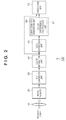
- Fig. 2 is a functional block diagram of an image capturing apparatus 100 according to the embodiment.
- the image capturing apparatus 100 includes an imaging optical system 10, an image sensor 20, an A/D conversion unit 30, a color separation unit 40, an edge extraction unit 50, a correction data generation unit 60 including a color difference calculation unit 61, and a correction unit 70.
- the imaging optical system 10 forms an object image on the image sensor 20.
- the image sensor 20 is a single-plate color image sensor in which photoelectric conversion elements are two-dimensionally arrayed and which includes a general primary color filter.
- the primary color filter has an arrangement in which three types of unit filters (R filters, G filters, and B filters) with dominant transmitted wavelength ranges in the vicinities of 650 nm, 550 nm, and 450 nm, respectively, are two-dimensionally arrayed such that unit filters of each type correspond to one photoelectric conversion element.
- each photoelectric conversion element receives light transmitted through unit filters of one type, and outputs an electrical signal indicating the intensity of the received light.
- each photoelectric conversion element of the single-plate color image sensor can only output the intensity of one of R, G, and B planes. This means that the captured image output from the image sensor 20 is a color mosaic image.
- the A/D conversion unit 30 converts the color mosaic image output from the image sensor 20 as an analog voltage into digital data suitable for subsequent image processing.
- the color separation unit 40 interpolates the color mosaic image to generate color images having full RGB color information in all pixels.
- the interpolation method may be of any of various proposed schemes, such as interpolation based on the value of a pixel which is in the vicinity of the target pixel and forms the same color plane as the latter, and interpolation based on the value of a pixel which is adjacent to the target pixel and forms a different color plane from the latter.
- the edge extraction unit 50 detects an edge from the generated color image. Based on information on the edge detected by the edge extraction unit 50, the correction data generation unit 60 obtains the amount of correction for chromatic aberration of magnification from the color image, and generates correction data for chromatic aberration of magnification. The correction unit 70 corrects the chromatic aberration of magnification of the color image using the correction data generated by the correction data generation unit 60.
- Fig. 3 is a flowchart showing the sequence of a process of correcting chromatic aberration of magnification by the edge extraction unit 50, correction data generation unit 60, and correction unit 70.
- the edge extraction unit 50 detects an edge from a color image generated by the color separation unit 40. This is because a color shift due to the chromatic aberration of magnification of the imaging optical system 10 conspicuously appears on the edge portion of the image.
- a Y (luminance) plane is used in detecting an edge from the image.
- the Y plane can be calculated using a known equation from R, G, and B planes. Alternatively, the value of a G plane may be used as a Y plane.
- an accurate amount of color shift can be obtained by limiting the edge to be detected in step S101 to an edge on which the pixel value considerably changes in the radial direction from the optical center. Note also that since a color shift due to chromatic aberration of magnification appears as a blur in the Y plane, an edge with a certain width, in which a predetermined number of successive pixels monotonically and successively increase or decrease in their values in the width direction, is detected.
- step S102 the correction data generation unit 60 obtains the amount of color shift on each edge detected in step S101. Details of an operation of obtaining the amount of color shift will be described later.
- the process in step S102 can be simplified upon determining, based on the positional relationship between the optical center and each edge, the direction of color shift to be obtained in step S102 as one of the upward/downward direction, the leftward/rightward direction, the oblique upper right/oblique lower left direction, and the oblique upper left/oblique lower right direction.
- the amount of color shift obtained in step S102 is assumed to have a negative value if the R plane (or the B plane) shifts toward the optical center with respect to the G plane, and have a positive value if the R plane (or the B plane) shifts in a direction opposite to the optical center.
- step S103 the correction data generation unit 60 generates correction data by obtaining the relationship between the image height and a color shift from the image height of each edge detected in step S101, and the amount of color shift on each edge obtained in step S102.
- the image height means herein the distance from a pixel (to be referred to as the image center or the optical center hereinafter) corresponding to the optical center.
- the edge detection and the color shift amount obtaining may be performed for all edges contained in the color image.
- the process efficiency can be improved, while sustaining a given reliability of the color shift rate, by ending both the detection of an edge belonging to each of the eight regions divided for each image height, and the color shift amount obtaining when color shift rates the number of which is equal to or larger than a certain threshold have been accumulated in the region.
- correction data can be generated even for regions where edges to be detected have not been found.
- step S104 the correction unit 70 uses the correction data generated in step S103 to apply color shift correction to the color image.
- the correction unit 70 obtains the color shift rate M using the correction data and the polynomial approximation F(1) in a pixel (X,Y) in planes (R and B planes) to be corrected, from the image height L of the pixel (X,Y).
- the pixel coordinates are represented by a coordinate system which uses the optical center as its origin (0,0).
- the correction unit 70 generates, by a general interpolation process, a pixel value corresponding to the coordinates (X1,Y1) in the planes to be corrected, and determines it as the pixel value of the pixel (X,Y). These operations are performed for all pixels to perform their color shift correction.
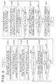
- step S102 Details of the color shift amount obtaining process in step S102 will be described next with reference to a flowchart shown in Fig. 5 .
- Fig. 5 shows a process of obtaining the amount of color shift between the G plane and the B plane
- the amount of color shift between the G plane and the R plane can be similarly obtained.
- the "B plane” is replaced with the "R plane” in the following description.
- the size of the region of interest can be set based on the width of the edge of interest and the amount of change in luminance.
- the width of the edge means the number of continuous pixels whose values monotonically increase or decrease in the Y plane where edge detection is to be performed. A satisfactory effect can be obtained upon setting, for example, a square region with a side length about three to five times the edge width as the region of interest.
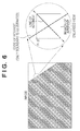
- One line (m pixels) which passes through the center of the region of interest and runs in the direction to obtain the amount of color shift (to be referred to as the line of interest hereinafter) is set as a region where the color difference is to be calculated (color difference obtaining region), as shown in Fig. 6 .
- the region of interest is at the upper right in the image, the amount of color shift is obtained in the oblique upper right/oblique lower left direction. That is, the orientation of the line of interest is determined based on where the edge is located in the image.
- More accurate color difference evaluation can be performed by correcting the pixel values within each line of interest in obtaining the color differences.
- the pixel values on the line of interest in the B plane can be corrected such that the maximum pixel value on the line of interest in the G plane becomes equal to that on the line of interest in the B plane.
- the color difference calculation unit 61 can obtain a color difference array C0[m] as:
- step S203 the correction data generation unit 60 moves the region of interest in the B plane by one pixel toward the optical center in the direction to detect the amount of color shift.
- the region of interest can be a region within the B plane, so may be smaller than the B plane, but may also correspond to the whole B plane.
- (x,y) be the coordinates of a pixel B1 on the upper left corner of the region of interest in the B plane
- the coordinates of the pixel on the upper left corner of the region of interest after the movement are (x-1,y-1).
- the correction data generation unit 60 obtains an absolute difference sum S0 by summing an absolute difference between the pixel G1 at (x,y) in the G plane and the pixel B1 at (x-1,y-1), an absolute difference between the pixel G2 at (x+1,y) in the G plane and the pixel B2 at (x,y-1),..., and absolute difference between the pixel Gn at (x+p,y+q) in the G plane and the pixel Bn at (x+p-1,y+q-1).
- step S204 the color difference calculation unit 61 calculates a color difference C[j] for each pair of pixels on the line of interest in the G plane and the line of interest in the region of interest in the moved B plane to obtain a color difference array C[m] consists of the calculated color differences between each pair of pixels, as in step S202.
- the line of interest is also moved as the plane to which the line of interest belongs is moved.
- step S205 the correction data generation unit 60 evaluates the obtained color differences.
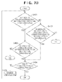
- Fig. 7A is a flowchart showing details of the color difference evaluation process in step S205.
- the correction data generation unit 60 obtains maximum and minimum values from the color difference array C0[m] before correction, which is obtained in step S202 (S301).
- the correction data generation unit 60 then uses a constant K to define thresholds Tmax and Tmin (S302) as:
- the constant K greatly differs depending on, for example, whether the image data is raw data or JPEG data, it is desirably decided based on the number of gray levels of pixels in both cases.
- the constant K may be about 100 to 150 for raw data with 16,383 gray levels.
- the constant K may be about 15 to 20 for a JPEG image with 255 gray levels.
- the correction data generation unit 60 obtains maximum and minimum values from a color difference array C[m] obtained in step S204 (S303), and determines whether the color difference is OK or NG by the following process using the thresholds Tmax and Tmin defined in step S302 (S304).
- step S304 it is determined in step S304 that the color difference is OK if the maximum value Cmax is equal to or smaller than the threshold Tmax and the minimum value Cmin is equal to or larger than the threshold Tmin; or that the color difference is NG otherwise.
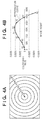
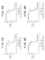
- Figs. 8A and 8B show the relationships between the thresholds Tmax and Tmin and the color difference arrays C0[m] and C[m].
- Fig. 8A shows the relationships between the set thresholds Tmax and Tmin and the color difference array C0[m] before correction.
- Fig. 8B shows the relationships between the thresholds Tmax and Tmin and the color difference array C[m] when the region of interest in the B plane has moved by one to three pixels.
- OK is determined if the region of interest has moved by one or two pixels, but NG is determined if it has moved by three pixels.
- Figs. 9A to 9D show the state of the edge before correction and those of the edge having undergone color shifts when the region of interest has moved by one to three pixels, respectively, in correspondence with Figs. 8A and 8B .
- step S206 is executed only when OK is determined upon the color difference evaluation in step S205.
- the correction data generation unit 60 obtains an absolute difference sum S[j], as in step S201, in the region of interest in the G plane and the region of interest in the moved B plane.
- step S207 the correction data generation unit 60 determines whether the region of interest has moved by a preset maximum distance. If the region of interest has not yet moved by the maximum distance, the process returns to step S203.
- the maximum distance of the region of interest must be larger than the amount of color shift. Nevertheless, an excessively large maximum distance lowers the process efficiency.
- the inventor of the present invention empirically concluded that a distance equal to the side length (that is, about three to five times the edge width) of the region of interest suffices as the maximum distance.
- step S205 If it is determined in step S205 that the color difference is NG, or it is determined in step S207 that the region of interest has moved by the maximum distance, the correction data generation unit 60 resets the region of interest in step S208.
- the region of interest in the B plane is returned to the position before correction, after color difference evaluation and absolute difference sum obtaining are performed while the region of interest in the B plane is sequentially moved toward the optical center in steps S203 to S207.
- steps S209 to S213 color difference evaluation and absolute difference sum obtaining are performed while the region of interest in the B plane is sequentially moved in a direction opposite to the optical center from the position before correction. Except for the moving direction of the region of interest, the processes in steps S209 to S213 are the same as in steps S203 to S207, respectively, and a description thereof will not be given.
- step S214 the correction data generation unit 60 detects a minimum value from the previously obtained absolute difference sums, and decides the distance of the region of interest for the minimum absolute difference sum as the amount of color shift. At this time, if the R plane (or the B plane) shifts toward the optical center with respect to the G plane, the amount of color shift is assumed as negative. In contrast, if the R plane (or the B plane) shifts in a direction opposite to the optical center with respect to the G plane, the amount of color shift is assumed as positive.
- the amount of color shift is not decided only by determination of the degree of similarity between pixel values based on the absolute difference sum, but is decided in the range in which overcorrection does not occur by determining, based on the amount of change in color difference, whether a change in color on the edge portion is expected to occur upon overcorrection. This makes it possible to obtain an appropriate amount of color shift which does not make the observer feel unnatural when he or she compares the edge portion before correction with that after correction.
- the amount of color shift may be obtained with an accuracy less than one pixel by interpolating the obtained absolute difference sums in determining a minimum absolute difference sum.
- the amount of color shift may be obtained with an accuracy less than one pixel by shifting the region of interest in steps of a unit less than one pixel by interpolating the pixels in the region of interest.
- color difference obtaining in steps S202 and S210 and color difference evaluation in steps S205 and S211 are performed for one-dimensional lines of interest in this embodiment, they may be performed for two-dimensional regions of interest as used for absolute difference sum obtaining. In this case as well, color difference evaluation in steps S205 and S211 can be implemented without requiring any changes except that in the latter regions of interest minimum and maximum values are detected within a two-dimensional range.
- the second embodiment of the present invention will be described next.
- the second embodiment is the same as the first embodiment except for a color difference evaluation method to be implemented in steps S205 and S111, and only the color difference evaluation method will be described.
- Fig. 7B is a flowchart for explaining details of color difference evaluation to be implemented in steps S205 and S211 in the second embodiment.
- a correction data generation unit 60 performs the procedure of:
- both the color difference evaluation thresholds Ta and Tb greatly differ depending on, for example, whether the image data is raw data or JPEG data, they are desirably decided based on the number of gray levels of pixels in both cases.
- both the color difference evaluation thresholds Ta and Tb may be about 100 to 150 for raw data with 16,383 gray levels.
- Both the color difference evaluation thresholds Ta and Tb may be about 15 to 20 for a JPEG image with 255 gray levels.
- color difference evaluation is performed for each pixel.
- correction which generates a pair of pixels with a color difference between them, that changes considerably, can be suppressed even if the maximum or minimum value of the color difference changes little on the lines of interest.
- the third embodiment of the present invention will be described next.
- the third embodiment is the same as the first and second embodiments except for a color difference evaluation method to be implemented in steps S205 and S211, and only the color difference evaluation method will be described.
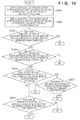
- Fig. 10 is a flowchart for explaining details of color difference evaluation to be implemented in steps S205 and S211 in the third embodiment.
- a correction data generation unit 60 uses a color difference calculation unit 61 to calculate the sum total of the positive values of color differences in the color difference array C0[m] before correction and that of the absolute values of the negative values of color differences in the color difference array C0[m] (S501), and to calculate the sum total of the positive values of color differences in the color difference array C[m] after correction and that of the absolute values of the negative values of color differences in the color difference array C[m] (S502).
- the correction data generation unit 60 determines whether the color difference is OK or NG by:
- the color difference evaluation threshold T greatly differs depending on, for example, whether the image data is raw data or JPEG data, it is desirably decided based on the number of gray levels of pixels and the size of the region of interest in both cases.
- the color difference is evaluated based on an increase/decrease in sum total of the positive values of the color difference before and after correction and in sum total of the absolute values of the negative values of this color difference.
- this evaluation is based on the overall change in color difference over the entire regions of interest before and after correction.
- the color difference evaluation methods described in the first to third embodiments are not exclusive, and may be used in combination.
- One of these determination methods may be dynamically selected in accordance with, for example, image features.
- the present invention is applied to an image capturing apparatus which includes an optical system and image sensor and exemplifies an image processing apparatus.
- an optical system and image sensor are not indispensable in the present invention.
- the amount of color shift can be obtained from arbitrary image data which has a plurality of color planes and is captured using an image sensing lens, and the image data format and the data obtaining method are not limited to specific ones.
- at least some of the A/D conversion unit 30, color separation unit 40, edge extraction unit 50, correction data generation unit 60, and correction unit 70 shown in Fig. 2 may be implemented by means of software using a computer serving as a control unit (not shown) of the image capturing apparatus 100.
- aspects of the present invention can also be realized by a computer of a system or apparatus (or devices such as a CPU or MPU) that reads out and executes a program recorded on a memory device to perform the functions of the above-described embodiment(s), and by a method, the steps of which are performed by a computer of a system or apparatus by, for example, reading out and executing a program recorded on a memory device to perform the functions of the above-described embodiment(s).
- the program is provided to the computer for example via a network or from a recording medium of various types serving as the memory device (for example, computer-readable medium).
- a further embodiment of the invention provides an image processing apparatus (100) arranged to correct a color shift in a captured image, wherein the captured image includes a plurality of color planes, the image processing apparatus comprising:
- An embodiment of the invention also provides a control method for an image processing apparatus arranged to correct a color shift in a captured image including a plurality of color planes, the method comprising the steps of:
- Another embodiment of the invention provides an image processing apparatus (100) that corrects a color shift in a captured image including a plurality of color planes, comprising:
- a still further embodiment of the invention provides a control method for an image processing apparatus (100) which corrects a color shift in a captured image including a plurality of color planes, comprising:
Landscapes
- Engineering & Computer Science (AREA)
- Multimedia (AREA)
- Signal Processing (AREA)
- Physics & Mathematics (AREA)
- Spectroscopy & Molecular Physics (AREA)
- Image Processing (AREA)
- Facsimile Image Signal Circuits (AREA)
- Color Television Image Signal Generators (AREA)
- Color Image Communication Systems (AREA)
Applications Claiming Priority (1)
| Application Number | Priority Date | Filing Date | Title |
|---|---|---|---|
| JP2009253523A JP5627215B2 (ja) | 2009-11-04 | 2009-11-04 | 画像処理装置及びその制御方法 |
Publications (3)
| Publication Number | Publication Date |
|---|---|
| EP2320665A2 EP2320665A2 (en) | 2011-05-11 |
| EP2320665A3 EP2320665A3 (en) | 2015-01-21 |
| EP2320665B1 true EP2320665B1 (en) | 2016-08-17 |
Family
ID=43414297
Family Applications (1)
| Application Number | Title | Priority Date | Filing Date |
|---|---|---|---|
| EP10188329.6A Not-in-force EP2320665B1 (en) | 2009-11-04 | 2010-10-21 | Image processing apparatus for chromatic aberration correction and control method therefor |
Country Status (4)
| Country | Link |
|---|---|
| US (1) | US8588521B2 (enExample) |
| EP (1) | EP2320665B1 (enExample) |
| JP (1) | JP5627215B2 (enExample) |
| CN (1) | CN102055988B (enExample) |
Families Citing this family (14)
| Publication number | Priority date | Publication date | Assignee | Title |
|---|---|---|---|---|
| CN102158731B (zh) * | 2011-05-26 | 2014-03-12 | 威盛电子股份有限公司 | 影像处理系统及方法 |
| CN102158730B (zh) * | 2011-05-26 | 2014-04-02 | 威盛电子股份有限公司 | 影像处理系统及方法 |
| JP5700012B2 (ja) * | 2012-09-20 | 2015-04-15 | コニカミノルタ株式会社 | 画像形成装置用キャリブレーション装置、キャリブレーション装置用プログラム、キャリブレーション装置用プログラムが記録されたコンピュータ読取可能な記録媒体、および画像形成装置のキャリブレーション方法 |
| JP5942755B2 (ja) * | 2012-09-28 | 2016-06-29 | 株式会社ソシオネクスト | 画像処理回路、画像処理方法及び撮像装置 |
| TWI485690B (zh) * | 2013-03-28 | 2015-05-21 | Innolux Corp | 應用於顯示器的顯示方法 |
| JP6066866B2 (ja) * | 2013-08-22 | 2017-01-25 | キヤノン株式会社 | 画像処理装置、その制御方法、および制御プログラム |
| JP6238673B2 (ja) * | 2013-10-08 | 2017-11-29 | キヤノン株式会社 | 画像処理装置、撮像装置、撮像システム、画像処理方法、画像処理プログラム、および、記憶媒体 |
| US10026192B2 (en) | 2013-10-18 | 2018-07-17 | Ford Global Technologies, Llc | Color harmony verification system |
| JP6512893B2 (ja) * | 2015-03-26 | 2019-05-15 | キヤノン株式会社 | 画像処理装置、撮像装置、画像処理方法及びコンピュータプログラム |
| JP7057159B2 (ja) * | 2018-03-02 | 2022-04-19 | キヤノン株式会社 | 画像処理装置、画像処理方法およびプログラム |
| JP7051580B2 (ja) * | 2018-05-21 | 2022-04-11 | キヤノン株式会社 | 画像処理装置、撮像装置、画像処理方法および画像処理プログラム |
| JP2020086578A (ja) * | 2018-11-16 | 2020-06-04 | 株式会社ジェイエイアイコーポレーション | 撮像装置 |
| KR20250023714A (ko) * | 2023-08-10 | 2025-02-18 | 주식회사 엘엑스세미콘 | 렌즈를 이용하여 이미지를 표시하는 디스플레이 장치 및 그 제어 방법 |
| CN117912416B (zh) * | 2024-01-23 | 2026-03-27 | 京东方科技集团股份有限公司 | 确定方法、确定装置、驱动装置、显示设备和计算机介质 |
Family Cites Families (12)
| Publication number | Priority date | Publication date | Assignee | Title |
|---|---|---|---|---|
| JP2000299874A (ja) | 1999-04-12 | 2000-10-24 | Sony Corp | 信号処理装置及び方法並びに撮像装置及び方法 |
| JP2002320237A (ja) * | 2001-04-20 | 2002-10-31 | Toshiba Corp | 倍率色収差の検出方法 |
| EP1746846B1 (en) * | 2004-04-12 | 2019-03-20 | Nikon Corporation | Image processing device having color shift-correcting function, image processing program, and electronic camera |
| JP4815807B2 (ja) | 2004-05-31 | 2011-11-16 | 株式会社ニコン | Rawデータから倍率色収差を検出する画像処理装置、画像処理プログラム、および電子カメラ |
| WO2007105359A1 (ja) * | 2006-03-01 | 2007-09-20 | Nikon Corporation | 倍率色収差を画像解析する画像処理装置、画像処理プログラム、電子カメラ、および画像処理方法 |
| JP4923987B2 (ja) * | 2006-11-30 | 2012-04-25 | 株式会社ニコン | 画像の色を補正する画像処理装置、および画像処理プログラム |
| KR100866490B1 (ko) * | 2007-01-17 | 2008-11-03 | 삼성전자주식회사 | 영상의 색 수차를 보정하기 위한 장치 및 방법 |
| JP5008578B2 (ja) * | 2008-01-28 | 2012-08-22 | 株式会社リコー | 画像処理方法、画像処理装置及び画像撮像装置 |
| JP5123756B2 (ja) * | 2008-06-26 | 2013-01-23 | オリンパス株式会社 | 撮像システム、画像処理方法および画像処理プログラム |
| JP5062846B2 (ja) * | 2008-07-04 | 2012-10-31 | 株式会社リコー | 画像撮像装置 |
| JP2010219683A (ja) * | 2009-03-13 | 2010-09-30 | Sony Corp | 画像処理装置、画像処理方法及びプログラム |
| CN201562069U (zh) * | 2009-04-10 | 2010-08-25 | 富士能株式会社 | 摄像透镜及摄像装置 |
-
2009
- 2009-11-04 JP JP2009253523A patent/JP5627215B2/ja active Active
-
2010
- 2010-10-21 EP EP10188329.6A patent/EP2320665B1/en not_active Not-in-force
- 2010-10-25 US US12/911,226 patent/US8588521B2/en active Active
- 2010-11-04 CN CN2010105350361A patent/CN102055988B/zh not_active Expired - Fee Related
Also Published As
| Publication number | Publication date |
|---|---|
| CN102055988B (zh) | 2013-07-17 |
| JP5627215B2 (ja) | 2014-11-19 |
| EP2320665A2 (en) | 2011-05-11 |
| US8588521B2 (en) | 2013-11-19 |
| EP2320665A3 (en) | 2015-01-21 |
| CN102055988A (zh) | 2011-05-11 |
| JP2011101129A (ja) | 2011-05-19 |
| US20110103686A1 (en) | 2011-05-05 |
Similar Documents
| Publication | Publication Date | Title |
|---|---|---|
| EP2320665B1 (en) | Image processing apparatus for chromatic aberration correction and control method therefor | |
| KR100782812B1 (ko) | 에지 적응적 컬러 보간 방법 및 장치 | |
| US7916937B2 (en) | Image processing device having color shift correcting function, image processing program and electronic camera | |
| KR101313686B1 (ko) | 화상처리장치 및 그 제어 방법 | |
| US7499089B2 (en) | Color interpolation method in bayer array | |
| JP5840008B2 (ja) | 画像処理装置、画像処理方法およびプログラム | |
| EP2742681B1 (en) | Image processing apparatus and control method therefor | |
| US20110267509A1 (en) | Image processing method and image processing device | |
| JP2006180099A (ja) | 画素欠陥補正装置 | |
| JP2010199650A (ja) | 画像処理装置および画像処理方法 | |
| JP2006067019A (ja) | 画像処理装置、撮影装置、画像処理方法、画像処理プログラムおよび記録媒体 | |
| EP2103979B1 (en) | Method for correcting chromatic aberration | |
| US7627237B2 (en) | Image processing apparatus and method and program | |
| US8817137B2 (en) | Image processing device, storage medium storing image processing program, and electronic camera | |
| KR20070103229A (ko) | 컬러 보간 방법 및 장치 | |
| EP2076021A2 (en) | Image processing apparatus and imaging apparatus | |
| US7656441B2 (en) | Hue correction for electronic imagers | |
| CN110290371A (zh) | 图像信号处理装置及图像处理电路 | |
| JP4994158B2 (ja) | 画像補正装置 | |
| US7489822B2 (en) | Image processing apparatus and method for detecting a direction of an edge in the vicinity of a pixel of interest and generating all color signals for each pixel by interpolation using color signals of a pixel of interest and its neighbor pixels, and a recording medium having a program recorded thereon for causing the apparatus to perform the method | |
| JP6274744B2 (ja) | 画像処理装置および画像処理方法 | |
| JP6105960B2 (ja) | 画像処理装置、画像処理方法、および撮像装置 | |
| JP3967217B2 (ja) | 画像処理方法、画像処理プログラム、画像処理プログラムを記録した記録媒体、画像処理装置、ならびに画像処理システム | |
| CN117041745A (zh) | 智能影像处理中的颜色插值方法及装置 | |
| JP2014086957A (ja) | 画像処理装置及び画像処理方法 |
Legal Events
| Date | Code | Title | Description |
|---|---|---|---|
| PUAI | Public reference made under article 153(3) epc to a published international application that has entered the european phase |
Free format text: ORIGINAL CODE: 0009012 |
|
| AK | Designated contracting states |
Kind code of ref document: A2 Designated state(s): AL AT BE BG CH CY CZ DE DK EE ES FI FR GB GR HR HU IE IS IT LI LT LU LV MC MK MT NL NO PL PT RO RS SE SI SK SM TR |
|
| AX | Request for extension of the european patent |
Extension state: BA ME |
|
| PUAL | Search report despatched |
Free format text: ORIGINAL CODE: 0009013 |
|
| AK | Designated contracting states |
Kind code of ref document: A3 Designated state(s): AL AT BE BG CH CY CZ DE DK EE ES FI FR GB GR HR HU IE IS IT LI LT LU LV MC MK MT NL NO PL PT RO RS SE SI SK SM TR |
|
| AX | Request for extension of the european patent |
Extension state: BA ME |
|
| RIC1 | Information provided on ipc code assigned before grant |
Ipc: H04N 9/04 20060101AFI20141218BHEP |
|
| 17P | Request for examination filed |
Effective date: 20150721 |
|
| RBV | Designated contracting states (corrected) |
Designated state(s): AL AT BE BG CH CY CZ DE DK EE ES FI FR GB GR HR HU IE IS IT LI LT LU LV MC MK MT NL NO PL PT RO RS SE SI SK SM TR |
|
| GRAP | Despatch of communication of intention to grant a patent |
Free format text: ORIGINAL CODE: EPIDOSNIGR1 |
|
| INTG | Intention to grant announced |
Effective date: 20160302 |
|
| GRAS | Grant fee paid |
Free format text: ORIGINAL CODE: EPIDOSNIGR3 |
|
| GRAA | (expected) grant |
Free format text: ORIGINAL CODE: 0009210 |
|
| AK | Designated contracting states |
Kind code of ref document: B1 Designated state(s): AL AT BE BG CH CY CZ DE DK EE ES FI FR GB GR HR HU IE IS IT LI LT LU LV MC MK MT NL NO PL PT RO RS SE SI SK SM TR |
|
| REG | Reference to a national code |
Ref country code: GB Ref legal event code: FG4D |
|
| REG | Reference to a national code |
Ref country code: CH Ref legal event code: EP |
|
| REG | Reference to a national code |
Ref country code: IE Ref legal event code: FG4D |
|
| REG | Reference to a national code |
Ref country code: AT Ref legal event code: REF Ref document number: 822058 Country of ref document: AT Kind code of ref document: T Effective date: 20160915 |
|
| REG | Reference to a national code |
Ref country code: DE Ref legal event code: R096 Ref document number: 602010035547 Country of ref document: DE |
|
| REG | Reference to a national code |
Ref country code: NL Ref legal event code: MP Effective date: 20160817 |
|
| REG | Reference to a national code |
Ref country code: LT Ref legal event code: MG4D |
|
| REG | Reference to a national code |
Ref country code: AT Ref legal event code: MK05 Ref document number: 822058 Country of ref document: AT Kind code of ref document: T Effective date: 20160817 |
|
| PG25 | Lapsed in a contracting state [announced via postgrant information from national office to epo] |
Ref country code: FI Free format text: LAPSE BECAUSE OF FAILURE TO SUBMIT A TRANSLATION OF THE DESCRIPTION OR TO PAY THE FEE WITHIN THE PRESCRIBED TIME-LIMIT Effective date: 20160817 Ref country code: RS Free format text: LAPSE BECAUSE OF FAILURE TO SUBMIT A TRANSLATION OF THE DESCRIPTION OR TO PAY THE FEE WITHIN THE PRESCRIBED TIME-LIMIT Effective date: 20160817 Ref country code: NO Free format text: LAPSE BECAUSE OF FAILURE TO SUBMIT A TRANSLATION OF THE DESCRIPTION OR TO PAY THE FEE WITHIN THE PRESCRIBED TIME-LIMIT Effective date: 20161117 Ref country code: NL Free format text: LAPSE BECAUSE OF FAILURE TO SUBMIT A TRANSLATION OF THE DESCRIPTION OR TO PAY THE FEE WITHIN THE PRESCRIBED TIME-LIMIT Effective date: 20160817 Ref country code: HR Free format text: LAPSE BECAUSE OF FAILURE TO SUBMIT A TRANSLATION OF THE DESCRIPTION OR TO PAY THE FEE WITHIN THE PRESCRIBED TIME-LIMIT Effective date: 20160817 Ref country code: LT Free format text: LAPSE BECAUSE OF FAILURE TO SUBMIT A TRANSLATION OF THE DESCRIPTION OR TO PAY THE FEE WITHIN THE PRESCRIBED TIME-LIMIT Effective date: 20160817 Ref country code: IT Free format text: LAPSE BECAUSE OF FAILURE TO SUBMIT A TRANSLATION OF THE DESCRIPTION OR TO PAY THE FEE WITHIN THE PRESCRIBED TIME-LIMIT Effective date: 20160817 |
|
| PG25 | Lapsed in a contracting state [announced via postgrant information from national office to epo] |
Ref country code: AT Free format text: LAPSE BECAUSE OF FAILURE TO SUBMIT A TRANSLATION OF THE DESCRIPTION OR TO PAY THE FEE WITHIN THE PRESCRIBED TIME-LIMIT Effective date: 20160817 Ref country code: LV Free format text: LAPSE BECAUSE OF FAILURE TO SUBMIT A TRANSLATION OF THE DESCRIPTION OR TO PAY THE FEE WITHIN THE PRESCRIBED TIME-LIMIT Effective date: 20160817 Ref country code: PT Free format text: LAPSE BECAUSE OF FAILURE TO SUBMIT A TRANSLATION OF THE DESCRIPTION OR TO PAY THE FEE WITHIN THE PRESCRIBED TIME-LIMIT Effective date: 20161219 Ref country code: BE Free format text: LAPSE BECAUSE OF NON-PAYMENT OF DUE FEES Effective date: 20161031 Ref country code: ES Free format text: LAPSE BECAUSE OF FAILURE TO SUBMIT A TRANSLATION OF THE DESCRIPTION OR TO PAY THE FEE WITHIN THE PRESCRIBED TIME-LIMIT Effective date: 20160817 Ref country code: SE Free format text: LAPSE BECAUSE OF FAILURE TO SUBMIT A TRANSLATION OF THE DESCRIPTION OR TO PAY THE FEE WITHIN THE PRESCRIBED TIME-LIMIT Effective date: 20160817 Ref country code: PL Free format text: LAPSE BECAUSE OF FAILURE TO SUBMIT A TRANSLATION OF THE DESCRIPTION OR TO PAY THE FEE WITHIN THE PRESCRIBED TIME-LIMIT Effective date: 20160817 Ref country code: GR Free format text: LAPSE BECAUSE OF FAILURE TO SUBMIT A TRANSLATION OF THE DESCRIPTION OR TO PAY THE FEE WITHIN THE PRESCRIBED TIME-LIMIT Effective date: 20161118 |
|
| PG25 | Lapsed in a contracting state [announced via postgrant information from national office to epo] |
Ref country code: RO Free format text: LAPSE BECAUSE OF FAILURE TO SUBMIT A TRANSLATION OF THE DESCRIPTION OR TO PAY THE FEE WITHIN THE PRESCRIBED TIME-LIMIT Effective date: 20160817 Ref country code: EE Free format text: LAPSE BECAUSE OF FAILURE TO SUBMIT A TRANSLATION OF THE DESCRIPTION OR TO PAY THE FEE WITHIN THE PRESCRIBED TIME-LIMIT Effective date: 20160817 |
|
| REG | Reference to a national code |
Ref country code: DE Ref legal event code: R097 Ref document number: 602010035547 Country of ref document: DE |
|
| PG25 | Lapsed in a contracting state [announced via postgrant information from national office to epo] |
Ref country code: BG Free format text: LAPSE BECAUSE OF FAILURE TO SUBMIT A TRANSLATION OF THE DESCRIPTION OR TO PAY THE FEE WITHIN THE PRESCRIBED TIME-LIMIT Effective date: 20161117 Ref country code: BE Free format text: LAPSE BECAUSE OF FAILURE TO SUBMIT A TRANSLATION OF THE DESCRIPTION OR TO PAY THE FEE WITHIN THE PRESCRIBED TIME-LIMIT Effective date: 20160817 Ref country code: SK Free format text: LAPSE BECAUSE OF FAILURE TO SUBMIT A TRANSLATION OF THE DESCRIPTION OR TO PAY THE FEE WITHIN THE PRESCRIBED TIME-LIMIT Effective date: 20160817 Ref country code: SM Free format text: LAPSE BECAUSE OF FAILURE TO SUBMIT A TRANSLATION OF THE DESCRIPTION OR TO PAY THE FEE WITHIN THE PRESCRIBED TIME-LIMIT Effective date: 20160817 Ref country code: CZ Free format text: LAPSE BECAUSE OF FAILURE TO SUBMIT A TRANSLATION OF THE DESCRIPTION OR TO PAY THE FEE WITHIN THE PRESCRIBED TIME-LIMIT Effective date: 20160817 Ref country code: DK Free format text: LAPSE BECAUSE OF FAILURE TO SUBMIT A TRANSLATION OF THE DESCRIPTION OR TO PAY THE FEE WITHIN THE PRESCRIBED TIME-LIMIT Effective date: 20160817 |
|
| REG | Reference to a national code |
Ref country code: CH Ref legal event code: PL |
|
| PLBE | No opposition filed within time limit |
Free format text: ORIGINAL CODE: 0009261 |
|
| STAA | Information on the status of an ep patent application or granted ep patent |
Free format text: STATUS: NO OPPOSITION FILED WITHIN TIME LIMIT |
|
| 26N | No opposition filed |
Effective date: 20170518 |
|
| REG | Reference to a national code |
Ref country code: IE Ref legal event code: MM4A |
|
| REG | Reference to a national code |
Ref country code: FR Ref legal event code: ST Effective date: 20170630 |
|
| PG25 | Lapsed in a contracting state [announced via postgrant information from national office to epo] |
Ref country code: CH Free format text: LAPSE BECAUSE OF NON-PAYMENT OF DUE FEES Effective date: 20161031 Ref country code: FR Free format text: LAPSE BECAUSE OF NON-PAYMENT OF DUE FEES Effective date: 20161102 Ref country code: LI Free format text: LAPSE BECAUSE OF NON-PAYMENT OF DUE FEES Effective date: 20161031 |
|
| PG25 | Lapsed in a contracting state [announced via postgrant information from national office to epo] |
Ref country code: SI Free format text: LAPSE BECAUSE OF FAILURE TO SUBMIT A TRANSLATION OF THE DESCRIPTION OR TO PAY THE FEE WITHIN THE PRESCRIBED TIME-LIMIT Effective date: 20160817 Ref country code: LU Free format text: LAPSE BECAUSE OF NON-PAYMENT OF DUE FEES Effective date: 20161021 |
|
| PG25 | Lapsed in a contracting state [announced via postgrant information from national office to epo] |
Ref country code: IE Free format text: LAPSE BECAUSE OF NON-PAYMENT OF DUE FEES Effective date: 20161021 |
|
| PG25 | Lapsed in a contracting state [announced via postgrant information from national office to epo] |
Ref country code: HU Free format text: LAPSE BECAUSE OF FAILURE TO SUBMIT A TRANSLATION OF THE DESCRIPTION OR TO PAY THE FEE WITHIN THE PRESCRIBED TIME-LIMIT; INVALID AB INITIO Effective date: 20101021 Ref country code: CY Free format text: LAPSE BECAUSE OF FAILURE TO SUBMIT A TRANSLATION OF THE DESCRIPTION OR TO PAY THE FEE WITHIN THE PRESCRIBED TIME-LIMIT Effective date: 20160817 |
|
| PG25 | Lapsed in a contracting state [announced via postgrant information from national office to epo] |
Ref country code: MT Free format text: LAPSE BECAUSE OF NON-PAYMENT OF DUE FEES Effective date: 20161031 Ref country code: MC Free format text: LAPSE BECAUSE OF FAILURE TO SUBMIT A TRANSLATION OF THE DESCRIPTION OR TO PAY THE FEE WITHIN THE PRESCRIBED TIME-LIMIT Effective date: 20160817 Ref country code: IS Free format text: LAPSE BECAUSE OF FAILURE TO SUBMIT A TRANSLATION OF THE DESCRIPTION OR TO PAY THE FEE WITHIN THE PRESCRIBED TIME-LIMIT Effective date: 20160817 Ref country code: TR Free format text: LAPSE BECAUSE OF FAILURE TO SUBMIT A TRANSLATION OF THE DESCRIPTION OR TO PAY THE FEE WITHIN THE PRESCRIBED TIME-LIMIT Effective date: 20160817 Ref country code: MK Free format text: LAPSE BECAUSE OF FAILURE TO SUBMIT A TRANSLATION OF THE DESCRIPTION OR TO PAY THE FEE WITHIN THE PRESCRIBED TIME-LIMIT Effective date: 20160817 |
|
| PG25 | Lapsed in a contracting state [announced via postgrant information from national office to epo] |
Ref country code: AL Free format text: LAPSE BECAUSE OF FAILURE TO SUBMIT A TRANSLATION OF THE DESCRIPTION OR TO PAY THE FEE WITHIN THE PRESCRIBED TIME-LIMIT Effective date: 20160817 |
|
| PGFP | Annual fee paid to national office [announced via postgrant information from national office to epo] |
Ref country code: DE Payment date: 20191227 Year of fee payment: 10 Ref country code: GB Payment date: 20191029 Year of fee payment: 10 |
|
| REG | Reference to a national code |
Ref country code: DE Ref legal event code: R119 Ref document number: 602010035547 Country of ref document: DE |
|
| GBPC | Gb: european patent ceased through non-payment of renewal fee |
Effective date: 20201021 |
|
| PG25 | Lapsed in a contracting state [announced via postgrant information from national office to epo] |
Ref country code: DE Free format text: LAPSE BECAUSE OF NON-PAYMENT OF DUE FEES Effective date: 20210501 |
|
| PG25 | Lapsed in a contracting state [announced via postgrant information from national office to epo] |
Ref country code: GB Free format text: LAPSE BECAUSE OF NON-PAYMENT OF DUE FEES Effective date: 20201021 |