EP2320095A2 - Hydraulische Baugruppe - Google Patents
Hydraulische Baugruppe Download PDFInfo
- Publication number
- EP2320095A2 EP2320095A2 EP10174444A EP10174444A EP2320095A2 EP 2320095 A2 EP2320095 A2 EP 2320095A2 EP 10174444 A EP10174444 A EP 10174444A EP 10174444 A EP10174444 A EP 10174444A EP 2320095 A2 EP2320095 A2 EP 2320095A2
- Authority
- EP
- European Patent Office
- Prior art keywords
- hydraulic
- pump
- assembly according
- hydraulic circuit
- cooler
- Prior art date
- Legal status (The legal status is an assumption and is not a legal conclusion. Google has not performed a legal analysis and makes no representation as to the accuracy of the status listed.)
- Granted
Links
Images

Classifications
-
- F—MECHANICAL ENGINEERING; LIGHTING; HEATING; WEAPONS; BLASTING
- F15—FLUID-PRESSURE ACTUATORS; HYDRAULICS OR PNEUMATICS IN GENERAL
- F15B—SYSTEMS ACTING BY MEANS OF FLUIDS IN GENERAL; FLUID-PRESSURE ACTUATORS, e.g. SERVOMOTORS; DETAILS OF FLUID-PRESSURE SYSTEMS, NOT OTHERWISE PROVIDED FOR
- F15B11/00—Servomotor systems without provision for follow-up action; Circuits therefor
- F15B11/16—Servomotor systems without provision for follow-up action; Circuits therefor with two or more servomotors
- F15B11/17—Servomotor systems without provision for follow-up action; Circuits therefor with two or more servomotors using two or more pumps
-
- B—PERFORMING OPERATIONS; TRANSPORTING
- B62—LAND VEHICLES FOR TRAVELLING OTHERWISE THAN ON RAILS
- B62D—MOTOR VEHICLES; TRAILERS
- B62D5/00—Power-assisted or power-driven steering
- B62D5/06—Power-assisted or power-driven steering fluid, i.e. using a pressurised fluid for most or all the force required for steering a vehicle
-
- B—PERFORMING OPERATIONS; TRANSPORTING
- B62—LAND VEHICLES FOR TRAVELLING OTHERWISE THAN ON RAILS
- B62D—MOTOR VEHICLES; TRAILERS
- B62D5/00—Power-assisted or power-driven steering
- B62D5/06—Power-assisted or power-driven steering fluid, i.e. using a pressurised fluid for most or all the force required for steering a vehicle
- B62D5/062—Details, component parts
-
- F—MECHANICAL ENGINEERING; LIGHTING; HEATING; WEAPONS; BLASTING
- F01—MACHINES OR ENGINES IN GENERAL; ENGINE PLANTS IN GENERAL; STEAM ENGINES
- F01P—COOLING OF MACHINES OR ENGINES IN GENERAL; COOLING OF INTERNAL-COMBUSTION ENGINES
- F01P7/00—Controlling of coolant flow
- F01P7/02—Controlling of coolant flow the coolant being cooling-air
- F01P7/04—Controlling of coolant flow the coolant being cooling-air by varying pump speed, e.g. by changing pump-drive gear ratio
- F01P7/044—Controlling of coolant flow the coolant being cooling-air by varying pump speed, e.g. by changing pump-drive gear ratio using hydraulic drives
-
- F—MECHANICAL ENGINEERING; LIGHTING; HEATING; WEAPONS; BLASTING
- F15—FLUID-PRESSURE ACTUATORS; HYDRAULICS OR PNEUMATICS IN GENERAL
- F15B—SYSTEMS ACTING BY MEANS OF FLUIDS IN GENERAL; FLUID-PRESSURE ACTUATORS, e.g. SERVOMOTORS; DETAILS OF FLUID-PRESSURE SYSTEMS, NOT OTHERWISE PROVIDED FOR
- F15B2211/00—Circuits for servomotor systems
- F15B2211/20—Fluid pressure source, e.g. accumulator or variable axial piston pump
- F15B2211/205—Systems with pumps
- F15B2211/20576—Systems with pumps with multiple pumps
-
- F—MECHANICAL ENGINEERING; LIGHTING; HEATING; WEAPONS; BLASTING
- F15—FLUID-PRESSURE ACTUATORS; HYDRAULICS OR PNEUMATICS IN GENERAL
- F15B—SYSTEMS ACTING BY MEANS OF FLUIDS IN GENERAL; FLUID-PRESSURE ACTUATORS, e.g. SERVOMOTORS; DETAILS OF FLUID-PRESSURE SYSTEMS, NOT OTHERWISE PROVIDED FOR
- F15B2211/00—Circuits for servomotor systems
- F15B2211/60—Circuit components or control therefor
- F15B2211/61—Secondary circuits
- F15B2211/611—Diverting circuits, e.g. for cooling or filtering
-
- F—MECHANICAL ENGINEERING; LIGHTING; HEATING; WEAPONS; BLASTING
- F15—FLUID-PRESSURE ACTUATORS; HYDRAULICS OR PNEUMATICS IN GENERAL
- F15B—SYSTEMS ACTING BY MEANS OF FLUIDS IN GENERAL; FLUID-PRESSURE ACTUATORS, e.g. SERVOMOTORS; DETAILS OF FLUID-PRESSURE SYSTEMS, NOT OTHERWISE PROVIDED FOR
- F15B2211/00—Circuits for servomotor systems
- F15B2211/60—Circuit components or control therefor
- F15B2211/62—Cooling or heating means
-
- F—MECHANICAL ENGINEERING; LIGHTING; HEATING; WEAPONS; BLASTING
- F15—FLUID-PRESSURE ACTUATORS; HYDRAULICS OR PNEUMATICS IN GENERAL
- F15B—SYSTEMS ACTING BY MEANS OF FLUIDS IN GENERAL; FLUID-PRESSURE ACTUATORS, e.g. SERVOMOTORS; DETAILS OF FLUID-PRESSURE SYSTEMS, NOT OTHERWISE PROVIDED FOR
- F15B2211/00—Circuits for servomotor systems
- F15B2211/70—Output members, e.g. hydraulic motors or cylinders or control therefor
- F15B2211/71—Multiple output members, e.g. multiple hydraulic motors or cylinders
- F15B2211/7142—Multiple output members, e.g. multiple hydraulic motors or cylinders the output members being arranged in multiple groups
Definitions
- the present invention relates to a hydraulic assembly for driving a fan in a commercial vehicle, in particular an agricultural utility vehicle.
- Such a vehicle generally has an internal combustion engine that provides high mechanical power for vehicle travel and, as needed, for driving various work and auxiliaries.
- the auxiliary equipment also includes a fan that drives a cooling air flow through an engine radiator and / or various other radiator of the vehicle. In order to achieve a good cooling effect with little use of drive energy, the fan should be mechanically coupled to the combustion engine without an intermediate energy conversion stage, such as an electric machine.
- the cooling requirement is not strictly correlated with the engine speed; Thus, the cooling requirement is low regardless of the engine load at a cold start or low outside temperatures.
- An operating condition called engine deceleration is characterized by the combination of low ones Speeds and high cooling demand. It is therefore necessary to be able to vary the ratio between the engine speed and the speed of the fan.
- a hydraulic circuit comprising an adjustable pump driven by the internal combustion engine and a hydraulic motor driving the fan.
- a hydraulic assembly for a utility vehicle comprising a first hydraulic circuit having a first pump that provides hydraulic power to an actuator of a power steering, and a second hydraulic circuit in which a second pump drives a hydraulic fan motor.
- the first hydraulic circuit includes a reservoir for hydraulic fluid, and both hydraulic circuits are connected by a common conduit section comprising a radiator and a filter.
- the object of the invention is to improve the energy efficiency of a hydraulic assembly of the type described above.
- the object is achieved by, in a hydraulic assembly for a particular agricultural utility vehicle with a first hydraulic circuit in which a first pump, an actuator, a power steering, a cooler for circulating in the first hydraulic circuit hydraulic fluid and a reservoir are connected in series, and a second hydraulic circuit in which a second pump and a hydraulic fan motor are connected in series and which has a line section common to the first hydraulic circuit, the two hydraulic circuits in the common line section have opposite directions of circulation.
- the throughput in the common line section corresponds to the difference instead of the sum of the delivery rates of the pumps. Since the power required to maintain the fluid flow in the common line section is proportional to the square of the flow rate, this measure leads to an improvement in energy efficiency.
- the cooler in the first hydraulic circuit is arranged downstream of the common line section.
- the cooler in the first hydraulic circuit is arranged downstream of the common line section.
- the pump of the second hydraulic circuit does not need to apply the driving power required to press the hydraulic fluid through the filter, which further improves the energy efficiency.
- the throughput of the first hydraulic circuit is only limited variable, since the drive power must be available for the actuator of the power steering at any time, the flow rate of the second hydraulic circuit in adaptation to the respective required fan power can be varied within wide limits. From the point of view of minimizing the pressure drop on the common line section, it is expedient if the throughput of the second pump can fluctuate around that of the first, so that the time-averaged throughput on the common line section can assume values close to zero.
- a directional control valve can expediently be provided in order to decouple the cooler from the first hydraulic circuit.
- the directional control valve is arranged in the first hydraulic circuit between the common line section and the radiator, so that the common line section is not decoupled with.
- the directional control valve may be controlled by a pressure applied to its inlet port. This pressure will be high, especially when the hydraulic fluid is cold and accordingly tough.
- the directional control valve is controlled by means of a temperature prevailing at the first hydraulic circuit.
- a temperature sensor is generally available to control the radiator temperature anyway and can be used with little effort to control the directional control valve.
- a wax element is used for the temperature-dependent control, in which the temperature-dependent Extension of a thermally coupled to the first hydraulic circuit wax mass drives an actuating movement of the directional control valve.
- a relief valve can be connected in parallel to the radiator in order to avoid this when the pressure drop across the radiator exceeds a limit value.
- the running direction of the fan motor can be reversed between a normal direction of travel and a direction of exception.
- deposits of dust or plant residues that are deposited during prolonged operation in a flow channel of the cooling air can be released and at least partially eliminated. This also increases the energy efficiency of the fan, since a same heat exchange performance at the cooler with reduced fan throughput can be achieved.
- the running direction of the fan can be fixed by the driver of the vehicle.
- a control can be provided which switches over the fan motor from the exception running direction to the normal direction of travel whenever the second pump is down-regulated to minimum throughput, ideally zero throughput. This ensures that at each start of the vehicle, the fan starts in the normal direction, and it is sufficient a one-time operation of a control element, for example shortly before switching off the internal combustion engine to a cleaning of the air duct and then return to normal operation.
- such a control takes the switching to the exception direction only when at the same time as exceeding the limit temperature and the throughput of the second pump is maximum, the performance of the fan can not be increased so.
- a directional control valve in the second hydraulic circuit is preferably arranged, which connects a connection of the fan motor optionally with a suction port or a pressure port of the second pump.
- the fan is preferably not only for ventilating the radiator of the first hydraulic circuit, but also for ventilating an internal combustion engine radiator and / or a charge air cooler and / or a transmission oil cooler.
- a temperature sensor can be provided on each individual of these coolers to regulate the performance of the fan in each case based on the temperature of that cooler, which has the highest air requirement.
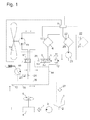
- a reservoir for the pressureless storage of hydraulic oil is in Fig. 1 denoted by 1.
- a suction line of a first hydraulic circuit extends to a pump 3, which is directly connected to and driven by an output shaft of an internal combustion engine (not shown) of the tractor.
- a servo motor 4 is connected via a pressure filter 7, which, controlled by a steering wheel 5, exerts a steering force on one or two steerable axles of the tractor.
- a first hydraulic oil cooler 6 Downstream of the servomotor 4, a first hydraulic oil cooler 6 is connected. Between the servomotor 4 and the radiator 6, a directional control valve 8 is inserted in the hydraulic circuit.
- the switching state of the directional control valve 8 can be controlled by a control circuit 9 as a function of the oil temperature measured by a temperature sensor 10 on the radiator 6; in the embodiment shown here, however, serves for this purpose a wax element 26, which is in close thermal contact with the circulating in the hydraulic circuit oil and its expansion when heating drives an adjustment of the directional control valve 8.
- the wax element 26 keeps the directional control valve 8 in a first switching state 8.1, in bypassing the radiator 6 on a line 11 directly from the output of the servomotor 4 via a return filter 27th is led back to the reservoir 1.
- the oil is therefore not cooled, and its temperature rises rapidly.
- the directional control valve 8 changes to a second switching state 8.2, in which part of the oil flow is directed via the radiator 6, while the remainder continues to be guided around the radiator 6 on the bypass line 11. As a result, the temperature rise of the oil is slowed down, but a steady value has not yet been reached.
- the directional control valve 8 Only when the oil temperature exceeds a second limit of, for example, 75 ° C, the directional control valve 8 goes into its third switching state 8.3, in which the path is blocked via the bypass line 11 and the entire oil flow over the radiator 6 runs. Since the increase in the oil temperature was slowed down even before the second limit value was exceeded, overheating of the oil during the transition to the third switching state of the directional control valve 8 can be avoided.
- a second limit of, for example, 75 ° C the directional control valve 8 goes into its third switching state 8.3, in which the path is blocked via the bypass line 11 and the entire oil flow over the radiator 6 runs. Since the increase in the oil temperature was slowed down even before the second limit value was exceeded, overheating of the oil during the transition to the third switching state of the directional control valve 8 can be avoided.
- a relief valve 12 is provided in parallel to the directional control valve 8 and the radiator 6, which is permeable when exceeding a limit pressure difference between its terminals.
- the relief valve 12 could replace the directional control valve 8, as effectively it passes through the radiator 6 and cold past it like this warm oil.
- the disadvantage is that the pressure required to open the relief valve 12 remains constantly present as oil passes therethrough so that the pump 3 must be able to provide a very high outlet pressure during a cold start to open the relief valve and to maintain a sufficiently high flow of oil.
- the reservoir 1, the pump 3, the servomotor 4, the radiator 6, the filters 7, 27 and the lines connecting them form a first hydraulic circuit.
- two branches 13, 14 are provided between an outlet of the servomotor 4 and the inlet of the directional control valve 8.
- a second hydraulic circuit has in common with the first one described above these two branches 13, 14 and a line piece 15 extending between them.
- a pump 16 with adjustable flow rate, a directional control valve 17 and a hydraulic motor 18 for driving a fan 19 are arranged.
- a suction port of the pump 16 is with connected upstream of the branching direction of the first hydraulic circuit upstream branch 13.
- a pressure port of the pump 16 is selectively connected via the directional control valve 17 with any of two different ports of the hydraulic motor 18, wherein the respective other port of the hydraulic motor 18 is connected via the directional control valve 17 to the downstream branch 14.
- the pump 16 thus drives an oil flow, which is opposite to that of the pump 3 on the common line piece 15. If the throughput of both pumps is the same, then the flow rate of the pipe section 15 is zero, and the entire oil pumped by the pump 3 also flows through the pump 16 and the hydraulic motor 18 in a series connection. If the flow rate of the pump 16 is smaller, then it is distributed the oil flow of the pump 3 on the line piece 15 on the one hand and the path leading through the pump 16 and the hydraulic motor 18 on the other hand. The entire oil flow passing through the pump 16 then also passes through the cooler 6 and the reservoir 1.
- the drive power required to maintain the high throughput of the pump 16 is low, since the circulating in a closed loop oil does not have to be pressed by the radiator 6 and the filter 7, 27. Overheating of the oil in the second cycle is still avoided because the pump 3 constantly supplies relatively cool oil with only a slightly variable delivery rate. Since the branches 13, 14 are spatially separated by the pipe section 15, this cool oil can not continue to flow to the radiator 6, bypassing the second hydraulic circuit, but is forced to mix with the circulating in this circle oil, so that in the closed Circle circulating oil is continuously exchanged.
- Hydraulic circuits that supply replaceable consumers generally have line couplings that can be closed or opened by a user when mounting and dismounting a consumer and through which contaminants can enter the hydraulic system.
- the first hydraulic circuit is free of such clutches, and the pressure filter 7 prevents impurities from such a hydraulic circuit via the tank 1 in the first hydraulic circuit in circulation.
- the circulating oil is therefore clean enough to possibly pass through the second hydraulic circuit several times in succession.
- one or more further coolers such as an engine cooler 20 in which cooling water circulated by a pump 25 circulates, belong to the units supplied with cooling air by the fan 19, a transmission oil cooler 21 and, if the internal combustion engine is associated with a compressor, a charge air cooler.
- Each of these further coolers 20, 21 is also assigned its own temperature sensor 22, and the control circuit 9 is connected to the sensors 22 in order to control the throughput of the pump 16 as a function of the detected temperature of that cooler 6, 20, 21; whose cooling requirements are recognized as the highest.
- the driver is shown a warning signal in order to inform him of the overheating. It is then up to the driver to set the pump 16 to minimum throughput. This causes the control circuit 9 to send a switching pulse to the directional control valve 17, this in its in Fig. 1 shown normal position offset, if it is not already in this. With the help of a control element on the dashboard, the driver can now switch the directional control valve 17 in its second position. When he returns the pump 16 to high, preferably maximum throughput, the hydraulic motor 18 reverses and blows air from behind through the radiator block. Deposited particles dissolve and are expelled from the radiator block. A subsequent standstill of the pumps 3, 16 triggers a renewed switching pulse to the directional control valve 17, so that it returns to the normal position and at the next start the fan 19 again runs in the normal direction.
- Fig. 2 shows a second embodiment of the ventilation assembly according to the invention. Their components are the same as in the embodiment of Fig. 1 and will not be explained again.
- the main difference to the design of the Fig. 1 is the placement of the common line section 15. Since in the embodiment of Fig. 2 the cooler 6 is arranged upstream of the common line section 15, the entire flow of oil circulated by the pump 3 passes through the cooler 6, so that leakage oil which escapes at the pump 16 or the motor 18 and is led back to the tank 1 via leakage oil lines 28, previously cooled. In the embodiment of Fig. 1 on the other hand, leakage oil which escapes at the pump 16 or the motor 18 reaches the tank 1 uncooled via the leak oil lines 28.
Landscapes
- Engineering & Computer Science (AREA)
- Mechanical Engineering (AREA)
- Chemical & Material Sciences (AREA)
- Combustion & Propulsion (AREA)
- Transportation (AREA)
- Physics & Mathematics (AREA)
- Fluid Mechanics (AREA)
- General Engineering & Computer Science (AREA)
- Fluid-Pressure Circuits (AREA)
- Motor Power Transmission Devices (AREA)
- Cooling, Air Intake And Gas Exhaust, And Fuel Tank Arrangements In Propulsion Units (AREA)
Abstract
Description
- Die vorliegende Erfindung betrifft eine hydraulische Baugruppe für den Antrieb eines Lüfters in einem Nutzfahrzeug, insbesondere einem landwirtschaftlichen Nutzfahrzeug.
- Ein solches Fahrzeug hat im Allgemeinen einen Verbrennungsmotor, der eine hohe mechanische Leistung für die Fortbewegung des Fahrzeugs sowie, nach Bedarf, zum Antreiben diverser Arbeits- und Hilfsaggregate bereitstellt. Zu den Hilfsaggregaten zählt auch ein Lüfter, der einen Kühlluftstrom über einen Motorkühler und/oder diverse andere Kühler des Fahrzeugs antreibt. Um eine gute Kühlwirkung bei geringem Einsatz an Antriebsenergie zu erreichen, sollte der Lüfter auf mechanischem Weg, ohne eine dazwischen liegende Energieumwandlungsstufe wie etwa eine elektrische Maschine, an den Verbrennungsmotor gekoppelt sein.
- Der Kühlungsbedarf ist nicht strikt mit der Motordrehzahl korreliert; so ist bei einem Kaltstart oder niedrigen Außentemperaturen der Kühlungsbedarf unabhängig von der Motorlast gering. Ein als Motordrückung bezeichneter Betriebszustand zeichnet sich gerade durch das Zusammentreffen von niedrigen Drehzahlen und hohem Kühlungsbedarf aus. Es ist daher notwendig, das Verhältnis zwischen Motordrehzahl und Drehzahl des Lüfters variieren zu können. Aus
US 4 738 330 undDE 198 25 759 A1 ist es bekannt, hierfür zwischen den Verbrennungsmotor und den Lüfter einen Hydraulikkreis einzufügen, der eine von dem Verbrennungsmotor angetriebene verstellbare Pumpe und einen den Lüfter antreibenden hydraulischen Motor umfasst. -
DE 198 25 759 A1 beschreibt insbesondere eine hydraulische Baugruppe für ein Nutzfahrzeug, die einen ersten Hydraulikkreis mit einer ersten Pumpe, die hydraulische Antriebsenergie für einen Stellantrieb einer Servolenkung liefert, und einen zweiten Hydraulikkreis umfasst, in dem eine zweite Pumpe einen hydraulischen Lüftermotor antreibt. Der erste Hydraulikkreis enthält ein Reservoir für Hydraulikfluid, und beide Hydraulikkreise hängen über einen gemeinsamen Leitungsabschnitt zusammen, der einen Kühler und einen Filter umfasst. Wenn die Pumpen beider Hydraulikkreise in Betrieb sind, addieren sich ihre Durchsätze an Kühler und Filter, und der daraus resultierende hohe Druckabfall auf dem gemeinsamen Leitungsabschnitt erfordert eine hohe Antriebsleistung an beiden Pumpen. Da die Pumpe des zweiten Hydraulikreises nur Öl ansaugen kann, das den Kühler durchlaufen hat, dauert es nach einem Kaltstart bei kaltem Wetter beträchtliche Zeit, bis das Öl des zweiten Hydraulikkreises eine stationäre Betriebstemperatur erreicht, in der es dünnflüssig genug für einen energieeffizienten Betrieb ist. Aufgabe der Erfindung ist, die Energieeffizienz einer hydraulischen Baugruppe der oben beschriebenen Art zu verbessern. - Die Aufgabe wird gelöst, indem bei einer hydraulischen Baugruppe für ein insbesondere landwirtschaftliches Nutzfahrzeug mit einem ersten Hydraulikkreis, in dem eine erste Pumpe, ein Stellantrieb, eine Servolenkung, ein Kühler für in dem ersten Hydraulikkreis zirkulierendes Hydraulikfluid und ein Reservoir in Reihe verbunden sind, und einem zweiten Hydraulikkreis, in dem eine zweite Pumpe und ein hydraulischer Lüftermotor in Reihe verbunden sind und der einen Leitungsabschnitt mit dem ersten Hydraulikkreis gemeinsam hat, die zwei Hydraulikkreise im gemeinsamen Leitungsabschnitt gegenläufige Zirkulationsrichtungen aufweisen. Dadurch entspricht der Durchsatz im gemeinsamen Leitungsabschnitt der Differenz anstatt der Summe der Förderraten der Pumpen. Da die zum Aufrechterhalten des Fluidstroms im gemeinsamen Leitungsabschnitt erforderliche Leistung proportional zum Quadrat des Durchsatzes ist, führt diese Maßnahme zu einer Verbesserung der Energieeffizienz.
- Zweckmäßig ist ferner, dass der Kühler im ersten Hydraulikkreis stromabwärts von dem gemeinsamen Leitungsabschnitt angeordnet ist. Indem folglich Hydraulikfluid den zweiten Hydraulikkreis durchläuft, bevor es den Kühler erreicht, kann es nach einem Kaltstart zügig eine geeignete Betriebstemperatur erreichen, in der es dünnflüssig genug für einen energieeffizienten Betrieb ist.
- Im Dauerbetrieb, wenn das Hydraulikfluid warm und dünnflüssig ist, kann ein Teil von ihm als Lecköl an Pumpe und Motor des zweiten Hydraulikkreises entweichen und über Leckleitungen zurück zum Tank gelangen. Dieses Leckfluid bleibt ungekühlt, wenn der Kühler stromabwärts vom gemeinsamen Leitungsabschnitt angeordnet ist, erwärmt den Tankinhalt und steigert dadurch zusätzlich die Leckrate. Um dies zu vermeiden, kann auch eine Platzierung des Kühlers stromaufwärts vom gemeinsamen Leitungsabschnitt zweckmäßig sein.
- Wenn der gemeinsame Leitungsabschnitt im ersten Hydraulikkreis stromabwärts von der ersten Pumpe und dem Stellantrieb angeordnet ist, ist Hydraulikfluid, das von der zweiten Pumpe angesaugt wird, durch Abwärme der ersten Pumpe und des Stellantriebs und von diesen geleistete Arbeit vorgewärmt.
- Da das im zweiten Hydraulikkreis zirkulierende Hydraulikfluid ständig mit einer dem Durchsatz des ersten Hydraulikkreises entsprechenden Rate ausgetauscht wird, kann eine ausreichende Filterung des Hydraulikfluids durch einen im ersten Hydraulikkreis außerhalb des gemeinsamen Leitungsabschnitts angeordneten Filter gewährleistet werden. Die Pumpe des zweiten Hydraulikkreises braucht daher nicht die zum Hindurchpressen des Hydraulikfluids durch den Filter erforderliche Antriebsleistung aufzubringen, was die Energieeffizienz nochmals verbessert.
- Während der Durchsatz des ersten Hydraulikkreises nur beschränkt veränderlich ist, da die Antriebsleistung für den Stellantrieb der Servolenkung jederzeit zur Verfügung stehen muss, kann der Durchsatz des zweiten Hydraulikkreises in Anpassung an die jeweils benötigte Lüfterleistung in weiten Grenzen variabel sein. Unter dem Gesichtspunkt der Minimierung des Druckabfalls auf dem gemeinsamen Leitungsabschnitt ist es zweckmäßig, wenn der Durchsatz der zweiten Pumpe um denjenigen der ersten schwanken kann, so dass der zeitlich gemittelte Durchsatz auf dem gemeinsamen Leitungsabschnitt Werte nahe Null annehmen kann.
- Um eine schnelle Erwärmung der gesamten Baugruppe bei einem Kaltstart zu ermöglichen, kann zweckmäßigerweise ein Wegeventil vorgesehen sein, um den Kühler aus dem ersten Hydraulikkreis auszukoppeln.
- Vorzugsweise ist das Wegeventil im ersten Hydraulikkreis zwischen dem gemeinsamen Leitungsabschnitt und dem Kühler angeordnet, so dass der gemeinsame Leitungsabschnitt nicht mit ausgekoppelt wird.
- Das Wegeventil kann durch einen an seinem Einlassanschluss anliegenden Druck gesteuert sein. Dieser Druck wird insbesondere dann hoch sein, wenn das Hydraulikfluid kalt und dementsprechend zäh ist. Vorzugsweise ist das Wegeventil jedoch anhand einer am ersten Hydraulikkreis herrschenden Temperatur gesteuert. Ein Temperaturfühler ist zur Regelung der Kühlertemperatur im Allgemeinen ohnehin vorhanden und kann mit geringem Aufwand zur Steuerung des Wegeventils nutzbar gemacht werden. Bevorzugt wird allerdings für die temperaturabhängige Steuerung ein Wachselement verwendet, bei dem die temperaturabhängige Ausdehnung einer thermisch an den ersten Hydraulikkreis gekoppelten Wachsmasse eine Stellbewegung des Wegeventils antreibt.
- Ergänzend oder auch anstelle des Wegeventils kann ein Entlastungsventil zum Kühler parallel geschaltet sein, um diesen zu umgehen, wenn der Druckabfall am Kühler einen Grenzwert übersteigt.
- Die Laufrichtung des Lüftermotors ist einer vorteilhaften Weiterbildung zufolge zwischen einer Normallaufrichtung und einer Ausnahmelaufrichtung umkehrbar. Durch Betrieb des Lüfters in der Ausnahmelaufrichtung können Ablagerungen von Staub oder Pflanzenresten, die sich bei längerem Betrieb in einem Strömungskanal der Kühlluft ablagern, gelöst und wenigstens zum Teil auch beseitigt werden. Auch dies steigert die Energieeffizienz des Lüfters, da eine gleiche Wärmeaustauschleistung am Kühler bei verringertem Lüfterdurchsatz erreichbar ist.
- Die Laufrichtung des Lüfters kann durch den Fahrer des Fahrzeugs festlegbar sein. Einer vorteilhaften Weiterbildung zufolge kann ein Steuerelement vorgesehen sein, das immer dann, wenn die zweite Pumpe auf minimalen Durchsatz, idealerweise Nulldurchsatz, heruntergeregelt ist, den Lüftermotor von der Ausnahmelaufrichtung auf die Normallaufrichtung umschaltet. So ist sichergestellt, dass bei jedem Start des Fahrzeugs der Lüfter in der Normallaufrichtung anläuft, und es genügt eine einmalige Betätigung eines Bedienelements, z.B. kurz vor Ausschalten des Verbrennungsmotors, um eine Reinigung des Luftkanals auszulösen und anschließend zum Normalbetrieb zurückzukehren.
- Es besteht auch die Möglichkeit, eine Reinigung des Luftkanals automatisch mit Hilfe eines Steuerelements herbeizuführen, das eingerichtet ist, den Lüftermotor auf die Ausnahmelaufrichtung umzuschalten, wenn die Temperatur des Hydraulikfluids oder eines Kühlers über einer Grenztemperatur liegt.
- Vorzugsweise nimmt ein solches Steuerelement die Umschaltung auf die Ausnahmelaufrichtung nur dann vor, wenn gleichzeitig mit der Überschreitung der Grenztemperatur auch der Durchsatz der zweiten Pumpe maximal ist, die Leistung des Lüfters also nicht mehr gesteigert werden kann.
- Um die Umschaltung des Lüfters zwischen Normal- und Ausnahmelaufrichtung zu ermöglichen, ist vorzugsweise ein Wegeventil im zweiten Hydraulikkreis angeordnet, das einen Anschluss des Lüftermotors wahlweise mit einem Sauganschluss oder einem Druckanschluss der zweiten Pumpe verbindet.
- In einem erfindungsgemäßen Nutzfahrzeug dient der Lüfter vorzugsweise nicht nur zur Belüftung des Kühlers des ersten Hydraulikkreises, sondern auch zur Belüftung eines Verbrennungsmotorkühlers und/oder eines Ladeluftkühlers und/oder eines Getriebeölkühlers. Dabei kann an jedem einzelnen dieser Kühler ein Temperaturfühler vorgesehen sein, um die Leistung des Lüfters jeweils anhand der Temperatur desjenigen Kühlers zu regeln, der den höchsten Luftbedarf aufweist.
- Weitere Merkmale und Vorteile der Erfindung ergeben sich aus der nachfolgenden Beschreibung von Ausführungsbeispielen unter Bezugnahme auf die beigefügten Figuren.
- Fig. 1 und 2
- zeigen jeweils ein Hydraulikdiagramm einer erfindungsgemäßen Lüftungsbau- gruppe eines Traktors.
- Ein Reservoir für die drucklose Speicherung von Hydrauliköl ist in
Fig. 1 mit 1 bezeichnet. Von einem tiefsten Punkt 2 des Reservoirs 1 aus erstreckt sich eine Saugleitung eines ersten Hydraulikkreises zu einer Pumpe 3, die unmittelbar mit einer Abtriebswelle einer (nicht dargestellten) Brennkraftmaschine des Traktors verbunden und durch diese angetrieben ist. Mit dem Druckanschluss der Pumpe 3 ist über ein Druckfilter 7 ein Servomotor 4 verbunden, der, gesteuert durch ein Lenkrad 5, eine Lenkkraft auf eine oder zwei lenkbare Achsen des Traktors ausübt. - Stromabwärts vom Servomotor 4 ist ein erster Hydraulikölkühler 6 angeschlossen. Zwischen dem Servomotor 4 und dem Kühler 6 ist ein Wegeventil 8 in den Hydraulikkreis eingefügt. Der Schaltzustand des Wegeventils 8 kann durch eine Steuerschaltung 9 in Abhängigkeit von der von einem Temperatursensor 10 an dem Kühler 6 gemessenen Öltemperatur gesteuert sein; bei der hier gezeigten Ausgestaltung jedoch dient zu diesem Zweck ein Wachselement 26, das in engem thermischem Kontakt mit dem in dem Hydraulikkreis zirkulierenden Öl steht und dessen Ausdehnung bei Erwärmung eine Verstellbewegung des Wegeventils 8 antreibt. Liegt die Temperatur des Öls unterhalb eines Grenzwerts von zum Beispiel 55°C, so hält das Wachselement 26 das Wegeventil 8 in einem ersten Schaltzustand 8.1, in der unter Umgehung des Kühlers 6 auf einer Leitung 11 direkt vom Ausgang des Servomotors 4 über einen Rücklauffilter 27 zurück zum Reservoir 1 geführt wird. Das Öl wird daher nicht gekühlt, und seine Temperatur steigt schnell.
- Wenn die Öltemperatur den ersten Grenzwert überschreitet, geht das Wegeventil 8 in einen zweiten Schaltzustand 8.2 über, in welchem ein Teil des Ölstroms über den Kühler 6 gelenkt wird, während der Rest weiterhin auf der Umgehungsleitung 11 um den Kühler 6 herumgeführt wird. Dadurch ist der Temperaturanstieg des Öls verlangsamt, ein stationärer Wert aber noch nicht erreicht.
- Erst wenn die Öltemperatur einen zweiten Grenzwert von zum Beispiel 75°C übersteigt, geht das Wegeventil 8 in seinen dritten Schaltzustand 8.3 über, in welchem der Weg über die Umgehungsleitung 11 gesperrt ist und der gesamte Ölstrom über den Kühler 6 läuft. Da bereits vor dem Überschreiten des zweiten Grenzwerts der Anstieg der Öltemperatur verlangsamt war, kann eine Überhitzung des Öls beim Übergang zum dritten Schaltzustand des Wegeventils 8 vermieden werden.
- Als eine Sicherheitsmaßnahme, insbesondere für den Fall, dass bei niedrigen Umgebungstemperaturen Ölreste, die deutlich kälter als die vom Sensor 10 erfasste Temperatur und dementsprechend zähflüssig sind, die Zirkulation behindern, ist parallel zu dem Wegeventil 8 und dem Kühler 6 ein Entlastungsventil 12 vorgesehen, das bei Überschreitung einer Grenzdruckdifferenz zwischen seinen Anschlüssen durchlässig wird.
- Einer vereinfachten Ausgestaltung zufolge könnte das Entlastungsventil 12 das Wegeventil 8 ersetzen, da es effektiv wie dieses warmes Öl durch den Kühler 6 hindurch und kaltes an ihm vorbeilenkt. Nachteilig ist jedoch, dass der zum Öffnen des Entlastungsventils 12 erforderliche Druck an diesem ständig bestehen bleibt, während Öl hindurchfließt, so dass die Pumpe 3 in der Lage sein muss, bei einem Kaltstart einen sehr hohen Ausgangsdruck zu liefern, um das Entlastungsventil zu öffnen und einen ausreichend hohen Ölstrom in Gang zu halten.
- Das Reservoir 1, die Pumpe 3, der Servomotor 4, der Kühler 6, die Filter 7, 27 und die sie verbindenden Leitungen bilden einen ersten Hydraulikkreis.
- In diesem ersten Hydraulikkreis sind zwischen einem Auslass des Servomotors 4 und dem Einlass des Wegeventils 8 zwei Verzweigungen 13, 14 vorgesehen. Ein zweiter Hydraulikkreis hat mit dem oben beschriebenen ersten diese zwei Verzweigungen 13, 14 und ein sich zwischen diesen erstreckendes Leitungsstück 15 gemeinsam. An einem zweiten sich zwischen den Verzweigungen 13, 14 erstreckenden Abschnitt des zweiten Hydraulikkreises sind eine Pumpe 16 mit verstellbarem Durchsatz, ein Wegeventil 17 und ein Hydraulikmotor 18 zum Antreiben eines Lüfters 19 angeordnet. Ein Sauganschluss der Pumpe 16 ist mit der bezogen auf die Zirkulationsrichtung des ersten Hydraulikkreises stromaufwärtigen Verzweigung 13 verbunden. Ein Druckanschluss der Pumpe 16 ist über das Wegeventil 17 wahlweise mit einem beliebigen von zwei verschiedenen Anschlüssen des Hydraulikmotors 18 verbunden, wobei der jeweils andere Anschluss des Hydraulikmotors 18 über das Wegeventil 17 mit der stromabwärtigen Verzweigung 14 verbunden ist. Die Pumpe 16 treibt somit einen Ölstrom an, der auf dem gemeinsamen Leitungsstück 15 demjenigen der Pumpe 3 entgegengesetzt ist. Ist der Durchsatz beider Pumpen derselbe, dann ist der Durchsatz des Leitungsstücks 15 Null, und das gesamte von der Pumpe 3 geförderte Öl fließt in einer Reihenschaltung auch durch die Pumpe 16 und den Hydraulikmotor 18. Ist der Durchsatz der Pumpe 16 kleiner, dann verteilt sich der Ölstrom der Pumpe 3 auf das Leitungsstück 15 einerseits und den über die Pumpe 16 und den Hydraulikmotor 18 führenden Weg andererseits. Der gesamte über die Pumpe 16 laufende Ölstrom passiert anschließend auch den Kühler 6 und das Reservoir 1.
- Wenn der Kühlbedarf der vom Lüfter 19 belüfteten Aggregate hoch ist und der Durchsatz der Pumpe 16 dementsprechend höher als derjenige der Pumpe 3 eingestellt ist, kehrt sich die Strömungsrichtung im Leitungsstück 15 um, so dass ein Teil des Öls im geschlossenen Kreislauf, von der Pumpe 16 und dem Hydraulikmotor 18 zur Verzweigung 14 und von dort über das Leitungsstück 15 zurück zur Verzweigung 13, zirkuliert.
- Die zur Aufrechterhaltung des hohen Durchsatzes erforderliche Antriebsleistung der Pumpe 16 ist gering, da das im geschlossenen Kreis umlaufende Öl nicht durch den Kühler 6 und die Filter 7, 27 gepresst werden muss. Eine Überhitzung des Öls im zweiten Kreislauf wird dennoch vermieden, da die Pumpe 3 ständig mit nur wenig veränderlicher Förderrate relativ kühles Öl nachliefert. Da die Verzweigungen 13, 14 durch das Leitungsstück 15 räumlich getrennt sind, kann dieses kühle Öl nicht unter Umgehung des zweiten Hydraulikkreises weiter zum Kühler 6 fließen, sondern ist gezwungen, sich mit dem in diesem Kreis zirkulierenden Öl zu mischen, so dass das im geschlossenen Kreis umlaufende Öl kontinuierlich ausgetauscht wird.
- Hydraulikkreise, die austauschbare Verbraucher versorgen, haben im Allgemeinen Leitungskupplungen, die von einem Benutzer beim An- und Abbau eines Verbrauchers geschlossen bzw. geöffnet werden und über die Verunreinigungen in das Hydrauliksystem gelangen können. Der erste Hydraulikkreis ist frei von solchen Kupplungen, und der Druckfilter 7 verhindert, dass Verunreinigungen aus einem solchen Hydraulikkreis über den Tank 1 im ersten Hydraulikkreis in Umlauf geraten. Das darin zirkulierende Öl ist daher sauber genug, um ggf. den zweiten Hydraulikkreis mehrmals hintereinander zu durchlaufen.
- Zu den vom Lüfter 19 mit Kühlluft versorgten Aggregaten gehören neben dem bereits beschriebenen Hydraulikölkühler 6 noch ein oder mehrere weitere Kühler, wie etwa ein Motorkühler 20, in dem von einer Pumpe 25 umgewälztes Kühlwasser zirkuliert, ein Getriebeölkühler 21 und, falls dem Verbrennungsmotor ein Kompressor zugeordnet ist, ein Ladeluftkühler. Auch diesen weiteren jeden Kühlern 20, 21 ist jeweils ein eigener Temperatursensor 22 zugeordnet, und die Steuerschaltung 9 ist mit den Sensoren 22 verbunden, um den Durchsatz der Pumpe 16 in Abhängigkeit von der erfassten Temperatur desjenigen Kühlers 6, 20, 21, zu steuern, dessen Kühlbedarf als am höchsten erkannt wird.
- Durch Umschalten des Wegeventils 17 ist es möglich, die Laufrichtung des Hydraulikmotors 18 und damit die Blasrichtung des Lüfters 19 umzukehren. Wenn zum Beispiel in an sich bekannter Weise ein Block mit den diversen Kühlern 6, 20, 21 unmittelbar an einem vorderen Ende der Karosserie des Traktors, hinter einem Kühlergrill oder dergleichen, angeordnet ist und dahinter der Lüfter 19 platziert ist, dann ist die normale Laufrichtung des Lüfters 19 so gewählt, dass dieser Luft durch den Kühlergrill und den dahinterliegenden Block der Kühler 6, 20, 21 saugt. Während des Betriebs des Lüfters lagern sich Partikel an den Kühlern 6, 20, 21 ab, die den Wärmeaustausch zwischen diesen und der hindurch streichenden Luft beeinträchtigen. Eine Erwärmung der Kühler wird von den Sensoren 10, 22 erfasst und veranlasst die Steuerschaltung 9 zunächst, die Förderrate der Pumpe 16 heraufzusetzen. Wenn jedoch die maximale Förderrate der Pumpe 16 erreicht ist und immer noch an wenigstens einem der Kühler 6, 20, 21 eine Überschreitung eines Temperaturgrenzwerts festgestellt wird, erkennt die Steuerschaltung 9, dass die Funktion der Kühler beeinträchtigt sein muss.
- Dies kann einer einfachen Ausgestaltung zufolge dazu führen, dass dem Fahrer ein Warnsignal angezeigt wird, um ihn auf die Überhitzung hinzuweisen. Es obliegt dann dem Fahrer, die Pumpe 16 auf minimalen Durchsatz zu stellen. Dies veranlasst die Steuerschaltung 9, einen Schaltimpuls an das Wegeventil 17 zu senden, der dieses in dessen in
Fig. 1 gezeigte Normalstellung versetzt, sofern es sich nicht bereits in dieser befindet. Mit Hilfe eines Bedienelements am Armaturenbrett kann der Fahrer nun das Wegeventil 17 in seine zweite Stellung umschalten. Wenn er die Pumpe 16 wieder auf hohen, vorzugsweise maximalen Durchsatz stellt, läuft der Hydraulikmotor 18 in umgekehrter Richtung und bläst Luft von hinten durch den Kühlerblock. Abgelagerte Partikel lösen sich und werden aus dem Kühlerblock ausgetrieben. Ein anschließender Stillstand der Pumpen 3, 16 löst einen neuerlichen Schaltimpuls an das Wegeventil 17 aus, so dass es zur Normalstellung zurückkehrt und beim nächsten Start der Lüfter 19 wieder in normaler Richtung läuft. - Denkbar ist auch, im Fehlerfall die Steuerschaltung 9 die Laufrichtung des Hydraulikmotors 18 im laufenden Betrieb umschalten zu lassen, wenn an einem der Kühler eine überhöhte Temperatur erfasst wird und die Förderrate der Pumpe 16 maximal ist. Um in einem solchen Fall Druckspitzen abzufangen, die während des Umschaltens des Wegeventils 17 auftreten können, sind zweckmäßigerweise ein Entlastungsventil 23 und ein Nachsaugventil 24 mit Saug- und Druckanschluss der Pumpe 16 verbunden.
-
Fig. 2 zeigt eine zweite Ausgestaltung der erfindungsgemäßen Lüftungsbaugruppe. Ihre Komponenten sind dieselben wie bei der Ausgestaltung derFig. 1 und werden nicht erneut erläutert. Der wesentliche Unterschied zur Ausgestaltung derFig. 1 ist die Platzierung des gemeinsamen Leitungsabschnitts 15. Da in der Ausgestaltung derFig. 2 der Kühler 6 stromaufwärts vom gemeinsamen Leitungsabschnitt 15 angeordnet ist, passiert der gesamte von der Pumpe 3 umgewälzte Ölstrom den Kühler 6, so dass auch Lecköl, das an der Pumpe 16 oder dem Motor 18 entweicht und über Leckölleitungen 28 zurück zum Tank 1 geführt wird, vorher gekühlt worden ist. Bei der Ausgestaltung derFig. 1 hingegen gelangt Lecköl, das an der Pumpe 16 oder dem Motor 18 entweicht, über die Leckölleitungen 28 ungekühlt zurück zum Tank 1. -
- 1
- Reservoir
- 2
- tiefster Punkt
- 3
- Pumpe
- 4
- Servomotor
- 5
- Lenkrad
- 6
- Hydraulikölkühler
- 7
- Druckfilter
- 8
- Wegeventil
- 9
- Steuerschaltung
- 10
- Temperatursensor
- 11
- Umgehungsleitung
- 12
- Entlastungsventil
- 13
- Verzweigung
- 14
- Verzweigung
- 15
- Leitungsstück
- 16
- Pumpe
- 17
- Wegeventil
- 18
- Hydraulikmotor
- 19
- Lüfter
- 20
- Motorkühler
- 21
- Getriebeölkühler
- 22
- Temperatursensor
- 23
- Entlastungsventil
- 24
- Nachsaugventil
- 25
- Pumpe
- 26
- Wachselement
- 27
- Rücklauffilter
- 28
- Leckölleitung
Claims (14)
- Hydraulische Baugruppe für ein insbesondere landwirtschaftliches Nutzfahrzeug, mit einem ersten Hydraulikkreis (1, 3, 4, 6, 7, 8, 27), in dem eine erste Pumpe (3), ein Stellantrieb (4) einer Servolenkung, ein Kühler (6) für in dem ersten Hydraulikkreis zirkulierendes Hydraulikfluid und ein Reservoir (1) in Reihe verbunden sind, und einem zweiten Hydraulikkreis (16, 17, 18), in dem eine zweite Pumpe (16) und ein hydraulischer Lüftermotor (18) in Reihe verbunden sind und der einen Leitungsabschnitt (15) mit dem ersten Hydraulikkreis (1, 3, 4, 6, 7, 8) gemeinsam hat, dadurch gekennzeichnet, dass die zwei Hydraulikkreise im gemeinsamen Leitungsabschnitt (15) gegenläufige Zirkulationsrichtungen aufweisen.
- Hydraulische Baugruppe nach Anspruch 1, dadurch gekennzeichnet, dass der Kühler (6) im ersten Hydraulikkreis stromabwärts oder stromaufwärts von dem gemeinsamen Leitungsabschnitt (15) angeordnet ist.
- Hydraulische Baugruppe nach Anspruch 1 oder 2, dadurch gekennzeichnet, dass ein Filter (7, 27) im ersten Hydraulikkreis außerhalb des gemeinsamen Leitungsabschnitts (15) angeordnet ist.
- Hydraulische Baugruppe nach Anspruch 1, 2 oder 3, dadurch gekennzeichnet, dass der Durchsatz pro Zeiteinheit der zweiten Pumpe (16) in weiterem Umfang variabel ist als der Durchsatz der ersten Pumpe (3).
- Hydraulische Baugruppe nach einem der vorhergehenden Ansprüche, gekennzeichnet durch ein Wegeventil (8), das angeordnet ist, um den Kühler (6) aus dem ersten Hydraulikkreis auszukoppeln.
- Hydraulische Baugruppe nach Anspruch 5, dadurch gekennzeichnet, dass das Wegeventil (8) im ersten Hydraulikkreis zwischen dem gemeinsamen Leitungsabschnitt (15) und dem Kühler (6) angeordnet ist.
- Hydraulische Baugruppe nach Anspruch 5 oder 6, dadurch gekennzeichnet, dass das Wegeventil (8) anhand einer am ersten Hydraulikkreis herrschenden Temperatur gesteuert ist.
- Hydraulische Baugruppe nach einem der vorhergehenden Ansprüche, dadurch gekennzeichnet, dass ein Entlastungsventil (12) parallel zu dem Kühler (6) angeordnet ist.
- Hydraulische Baugruppe nach einem der vorhergehenden Ansprüche, dadurch gekennzeichnet, dass die Laufrichtung des Lüftermotors (18) zwischen einer Normallaufrichtung und einer Ausnahmelaufrichtung umkehrbar ist.
- Hydraulische Baugruppe nach Anspruch 9, dadurch gekennzeichnet, dass ein Steuerelement (9) eingerichtet ist, den Lüftermotor (18) von der Ausnahmelaufrichtung auf die Normallaufrichtung umzuschalten, wenn die Pumpe (16) auf minimalen Durchsatz eingestellt ist.
- Hydraulische Baugruppe nach Anspruch 9, dadurch gekennzeichnet, dass ein Steuerelement (9) eingerichtet ist, den Lüftermotor (18) auf die Ausnahmelaufrichtung umzuschalten, wenn die Temperatur des Hydraulikfluids über einer Grenztemperatur liegt.
- Hydraulische Baugruppe nach Anspruch 11, dadurch gekennzeichnet, dass das Steuerelement (9) eingerichtet ist, die Umschaltung auf die Ausnahmelaufrichtung nur vorzunehmen, wenn die Grenztemperatur überschritten und gleichzeitig der Durchsatz der zweiten Pumpe (16) maximal ist.
- Hydraulische Baugruppe nach einem der Ansprüche 9 bis 12, dadurch gekennzeichnet, dass ein Wegeventil (17) im zweiten Hydraulikkreis angeordnet ist, um einen Anschluss des Lüftermotors (18) wahlweise mit einem Sauganschluss oder einem Druckanschluss der zweiten Pumpe (16) zu verbinden.
- Nutzfahrzeug, insbesondere landwirtschaftliches Fahrzeug, dadurch gekennzeichnet, dass der Lüfter (19) einer hydraulischen Baugruppe nach einem der vorhergehenden Ansprüche angeordnet ist, um neben dem Kühler (6) des ersten Hydraulikkreises einen Verbrennungsmotorkühler (20) und/oder einen Ladeluftkühler und/oder einen Getriebeölkühler (21) mit Luft zu versorgen.
Applications Claiming Priority (1)
| Application Number | Priority Date | Filing Date | Title |
|---|---|---|---|
| DE102009052258A DE102009052258A1 (de) | 2009-11-06 | 2009-11-06 | Hydraulische Baugruppe |
Publications (3)
| Publication Number | Publication Date |
|---|---|
| EP2320095A2 true EP2320095A2 (de) | 2011-05-11 |
| EP2320095A3 EP2320095A3 (de) | 2013-10-30 |
| EP2320095B1 EP2320095B1 (de) | 2017-04-12 |
Family
ID=43587194
Family Applications (1)
| Application Number | Title | Priority Date | Filing Date |
|---|---|---|---|
| EP10174444.9A Active EP2320095B1 (de) | 2009-11-06 | 2010-08-30 | Hydraulische Baugruppe |
Country Status (2)
| Country | Link |
|---|---|
| EP (1) | EP2320095B1 (de) |
| DE (1) | DE102009052258A1 (de) |
Families Citing this family (2)
| Publication number | Priority date | Publication date | Assignee | Title |
|---|---|---|---|---|
| DE102012101806A1 (de) | 2012-03-05 | 2013-09-05 | Claas Selbstfahrende Erntemaschinen Gmbh | Hydrauliksystem für eine selbstfahrende Arbeitsmaschine |
| DE102014111025B4 (de) | 2014-08-04 | 2025-03-20 | Linde Material Handling Gmbh | Hydraulische Schaltung zur Steuerung eines hydraulischen Lüfterantriebs eines Antriebssystems |
Citations (2)
| Publication number | Priority date | Publication date | Assignee | Title |
|---|---|---|---|---|
| US4738330A (en) | 1985-03-22 | 1988-04-19 | Nippondenso Co., Ltd. | Hydraulic drive system for use with vehicle power steering pump |
| DE19825759A1 (de) | 1997-06-10 | 1999-02-04 | Sauer Inc | Hydraulische Antriebsbaugruppe |
Family Cites Families (6)
| Publication number | Priority date | Publication date | Assignee | Title |
|---|---|---|---|---|
| DE10315495A1 (de) * | 2003-04-04 | 2004-10-21 | Linde Ag | Hydraulikanlage für Flurförderzeuge |
| US7155907B2 (en) * | 2004-03-23 | 2007-01-02 | Yvon Clarence Desjardins | Electro-hydraulic fan drive cooling and steering system for vehicle |
| DE102004025763A1 (de) * | 2004-05-26 | 2005-12-22 | Zf Friedrichshafen Ag | Antriebsanordnung für ein Fahrzeug |
| US7360357B2 (en) * | 2005-03-07 | 2008-04-22 | Parker-Hannifin Corporation | Hydraulic steering system with input horsepower limiting circuit and increased fan speeds at low engine RPM |
| DE102007032005A1 (de) * | 2007-07-09 | 2009-01-15 | Claas Selbstfahrende Erntemaschinen Gmbh | Fahrzeug mit hydrostatischem Fahrantrieb |
| DE102008012399B4 (de) * | 2008-03-04 | 2019-01-24 | Still Gmbh | Hydraulikanlage eines Flurförderzeugs |
-
2009
- 2009-11-06 DE DE102009052258A patent/DE102009052258A1/de not_active Withdrawn
-
2010
- 2010-08-30 EP EP10174444.9A patent/EP2320095B1/de active Active
Patent Citations (2)
| Publication number | Priority date | Publication date | Assignee | Title |
|---|---|---|---|---|
| US4738330A (en) | 1985-03-22 | 1988-04-19 | Nippondenso Co., Ltd. | Hydraulic drive system for use with vehicle power steering pump |
| DE19825759A1 (de) | 1997-06-10 | 1999-02-04 | Sauer Inc | Hydraulische Antriebsbaugruppe |
Also Published As
| Publication number | Publication date |
|---|---|
| DE102009052258A1 (de) | 2011-05-12 |
| EP2320095B1 (de) | 2017-04-12 |
| EP2320095A3 (de) | 2013-10-30 |
Similar Documents
| Publication | Publication Date | Title |
|---|---|---|
| EP1588076B1 (de) | Kühlkreislauf, insbesondere für ein kraftfahrzeuggetriebe | |
| DE102012209681B4 (de) | Fahrzeug mit zwei kühlergrillöffnungen und einer vor einer der kühlergrillöffnungen angeordneten verschlussanordnung | |
| DE60011167T2 (de) | Kühlvorrichtung für ein Kraftfahrzeug | |
| DE4320145C2 (de) | Klimaanlage für Kraftfahrzeuge | |
| DE3738412A1 (de) | Vorrichtung und verfahren zur motorkuehlung | |
| DE4033551A1 (de) | Klimaanlage fuer fahrzeuge | |
| DE102017215984B4 (de) | Steuermodul zur Klimatisierung einer Batterie | |
| DE2943526C2 (de) | Vorrichtung zum Anwärmen der Druckflüssigkeit für die Arbeitshydraulik eines Kraftfahrzeugs | |
| DE2623621C2 (de) | Einrichtung zum Beheizen der Bedienungskabine einer Maschine | |
| EP0143314A1 (de) | Kühlflüssigkeitskreislauf für ein- und ausrückbare Kupplungen, insbesondere in Fahrzeugen | |
| DE102012102404A1 (de) | Kälteanlage | |
| DE3635353A1 (de) | Klimaanlage an einem kraftfahrzeug | |
| EP2320095B1 (de) | Hydraulische Baugruppe | |
| WO2000004283A1 (de) | Vorrichtung zum kühlen eines motors für ein kraftfahrzeug | |
| DE3700037C2 (de) | Kühlanlage für die gemeinsame Kühlflüssigkeit der Antriebsmaschine sowie eines Retarders eines Fahrzeuges | |
| DE2235183C3 (de) | Kühlvorrichtung für eine ein Kraftfahrzeug antreibende Brennkraftmaschine | |
| DE3203927A1 (de) | Heiz- und belueftungseinrichtung fuer den fahrgastraum eines kraftfahrzeuges | |
| EP1282762A1 (de) | Kühlsystem für fahrzeuge | |
| DE4431041C2 (de) | Verfahren und Vorrichtung zur selbstadaptiven Steuerung einer Kraftfahrzeugheizung | |
| DE2651232A1 (de) | Kraftfahrzeugheizung | |
| DE2627734C3 (de) | Klimatisier- und Lüftungsvorrichtung mit Wärmerückgewinnung | |
| EP2913599B1 (de) | Klimatisierungseinrichtung | |
| EP3480534B1 (de) | Heizungsanlage und steuerverfahren für eine heizungsanlage | |
| DE102005002807B3 (de) | Heizeinrichtung für ein Fahrzeug, insbesondere für ein Kraftfahrzeug, sowie Verfahren zum Betreiben einer Heizeinrichtung | |
| EP1730459B1 (de) | Kühlkreislaufvorrichtung |
Legal Events
| Date | Code | Title | Description |
|---|---|---|---|
| PUAI | Public reference made under article 153(3) epc to a published international application that has entered the european phase |
Free format text: ORIGINAL CODE: 0009012 |
|
| AK | Designated contracting states |
Kind code of ref document: A2 Designated state(s): AL AT BE BG CH CY CZ DE DK EE ES FI FR GB GR HR HU IE IS IT LI LT LU LV MC MK MT NL NO PL PT RO SE SI SK SM TR |
|
| AX | Request for extension of the european patent |
Extension state: BA ME RS |
|
| PUAL | Search report despatched |
Free format text: ORIGINAL CODE: 0009013 |
|
| AK | Designated contracting states |
Kind code of ref document: A3 Designated state(s): AL AT BE BG CH CY CZ DE DK EE ES FI FR GB GR HR HU IE IS IT LI LT LU LV MC MK MT NL NO PL PT RO SE SI SK SM TR |
|
| AX | Request for extension of the european patent |
Extension state: BA ME RS |
|
| RIC1 | Information provided on ipc code assigned before grant |
Ipc: F15B 11/17 20060101AFI20130926BHEP Ipc: B62D 5/06 20060101ALI20130926BHEP Ipc: F01P 7/04 20060101ALI20130926BHEP |
|
| 17P | Request for examination filed |
Effective date: 20140430 |
|
| RBV | Designated contracting states (corrected) |
Designated state(s): AL AT BE BG CH CY CZ DE DK EE ES FI FR GB GR HR HU IE IS IT LI LT LU LV MC MK MT NL NO PL PT RO SE SI SK SM TR |
|
| RAP1 | Party data changed (applicant data changed or rights of an application transferred) |
Owner name: CLAAS SELBSTFAHRENDE ERNTEMASCHINEN GMBH |
|
| GRAP | Despatch of communication of intention to grant a patent |
Free format text: ORIGINAL CODE: EPIDOSNIGR1 |
|
| INTG | Intention to grant announced |
Effective date: 20161216 |
|
| GRAS | Grant fee paid |
Free format text: ORIGINAL CODE: EPIDOSNIGR3 |
|
| GRAA | (expected) grant |
Free format text: ORIGINAL CODE: 0009210 |
|
| AK | Designated contracting states |
Kind code of ref document: B1 Designated state(s): AL AT BE BG CH CY CZ DE DK EE ES FI FR GB GR HR HU IE IS IT LI LT LU LV MC MK MT NL NO PL PT RO SE SI SK SM TR |
|
| REG | Reference to a national code |
Ref country code: GB Ref legal event code: FG4D Free format text: NOT ENGLISH |
|
| REG | Reference to a national code |
Ref country code: CH Ref legal event code: EP |
|
| REG | Reference to a national code |
Ref country code: IE Ref legal event code: FG4D Free format text: LANGUAGE OF EP DOCUMENT: GERMAN |
|
| REG | Reference to a national code |
Ref country code: AT Ref legal event code: REF Ref document number: 884206 Country of ref document: AT Kind code of ref document: T Effective date: 20170515 |
|
| REG | Reference to a national code |
Ref country code: DE Ref legal event code: R096 Ref document number: 502010013447 Country of ref document: DE |
|
| REG | Reference to a national code |
Ref country code: NL Ref legal event code: MP Effective date: 20170412 |
|
| REG | Reference to a national code |
Ref country code: FR Ref legal event code: PLFP Year of fee payment: 8 |
|
| REG | Reference to a national code |
Ref country code: LT Ref legal event code: MG4D |
|
| PG25 | Lapsed in a contracting state [announced via postgrant information from national office to epo] |
Ref country code: NL Free format text: LAPSE BECAUSE OF FAILURE TO SUBMIT A TRANSLATION OF THE DESCRIPTION OR TO PAY THE FEE WITHIN THE PRESCRIBED TIME-LIMIT Effective date: 20170412 |
|
| PG25 | Lapsed in a contracting state [announced via postgrant information from national office to epo] |
Ref country code: HR Free format text: LAPSE BECAUSE OF FAILURE TO SUBMIT A TRANSLATION OF THE DESCRIPTION OR TO PAY THE FEE WITHIN THE PRESCRIBED TIME-LIMIT Effective date: 20170412 Ref country code: FI Free format text: LAPSE BECAUSE OF FAILURE TO SUBMIT A TRANSLATION OF THE DESCRIPTION OR TO PAY THE FEE WITHIN THE PRESCRIBED TIME-LIMIT Effective date: 20170412 Ref country code: GR Free format text: LAPSE BECAUSE OF FAILURE TO SUBMIT A TRANSLATION OF THE DESCRIPTION OR TO PAY THE FEE WITHIN THE PRESCRIBED TIME-LIMIT Effective date: 20170713 Ref country code: LT Free format text: LAPSE BECAUSE OF FAILURE TO SUBMIT A TRANSLATION OF THE DESCRIPTION OR TO PAY THE FEE WITHIN THE PRESCRIBED TIME-LIMIT Effective date: 20170412 Ref country code: ES Free format text: LAPSE BECAUSE OF FAILURE TO SUBMIT A TRANSLATION OF THE DESCRIPTION OR TO PAY THE FEE WITHIN THE PRESCRIBED TIME-LIMIT Effective date: 20170412 Ref country code: NO Free format text: LAPSE BECAUSE OF FAILURE TO SUBMIT A TRANSLATION OF THE DESCRIPTION OR TO PAY THE FEE WITHIN THE PRESCRIBED TIME-LIMIT Effective date: 20170712 |
|
| PG25 | Lapsed in a contracting state [announced via postgrant information from national office to epo] |
Ref country code: PL Free format text: LAPSE BECAUSE OF FAILURE TO SUBMIT A TRANSLATION OF THE DESCRIPTION OR TO PAY THE FEE WITHIN THE PRESCRIBED TIME-LIMIT Effective date: 20170412 Ref country code: SE Free format text: LAPSE BECAUSE OF FAILURE TO SUBMIT A TRANSLATION OF THE DESCRIPTION OR TO PAY THE FEE WITHIN THE PRESCRIBED TIME-LIMIT Effective date: 20170412 Ref country code: IS Free format text: LAPSE BECAUSE OF FAILURE TO SUBMIT A TRANSLATION OF THE DESCRIPTION OR TO PAY THE FEE WITHIN THE PRESCRIBED TIME-LIMIT Effective date: 20170812 Ref country code: BG Free format text: LAPSE BECAUSE OF FAILURE TO SUBMIT A TRANSLATION OF THE DESCRIPTION OR TO PAY THE FEE WITHIN THE PRESCRIBED TIME-LIMIT Effective date: 20170712 Ref country code: LV Free format text: LAPSE BECAUSE OF FAILURE TO SUBMIT A TRANSLATION OF THE DESCRIPTION OR TO PAY THE FEE WITHIN THE PRESCRIBED TIME-LIMIT Effective date: 20170412 |
|
| REG | Reference to a national code |
Ref country code: DE Ref legal event code: R097 Ref document number: 502010013447 Country of ref document: DE |
|
| PG25 | Lapsed in a contracting state [announced via postgrant information from national office to epo] |
Ref country code: RO Free format text: LAPSE BECAUSE OF FAILURE TO SUBMIT A TRANSLATION OF THE DESCRIPTION OR TO PAY THE FEE WITHIN THE PRESCRIBED TIME-LIMIT Effective date: 20170412 Ref country code: DK Free format text: LAPSE BECAUSE OF FAILURE TO SUBMIT A TRANSLATION OF THE DESCRIPTION OR TO PAY THE FEE WITHIN THE PRESCRIBED TIME-LIMIT Effective date: 20170412 Ref country code: CZ Free format text: LAPSE BECAUSE OF FAILURE TO SUBMIT A TRANSLATION OF THE DESCRIPTION OR TO PAY THE FEE WITHIN THE PRESCRIBED TIME-LIMIT Effective date: 20170412 Ref country code: SK Free format text: LAPSE BECAUSE OF FAILURE TO SUBMIT A TRANSLATION OF THE DESCRIPTION OR TO PAY THE FEE WITHIN THE PRESCRIBED TIME-LIMIT Effective date: 20170412 Ref country code: EE Free format text: LAPSE BECAUSE OF FAILURE TO SUBMIT A TRANSLATION OF THE DESCRIPTION OR TO PAY THE FEE WITHIN THE PRESCRIBED TIME-LIMIT Effective date: 20170412 |
|
| PLBE | No opposition filed within time limit |
Free format text: ORIGINAL CODE: 0009261 |
|
| STAA | Information on the status of an ep patent application or granted ep patent |
Free format text: STATUS: NO OPPOSITION FILED WITHIN TIME LIMIT |
|
| PG25 | Lapsed in a contracting state [announced via postgrant information from national office to epo] |
Ref country code: SM Free format text: LAPSE BECAUSE OF FAILURE TO SUBMIT A TRANSLATION OF THE DESCRIPTION OR TO PAY THE FEE WITHIN THE PRESCRIBED TIME-LIMIT Effective date: 20170412 Ref country code: IT Free format text: LAPSE BECAUSE OF FAILURE TO SUBMIT A TRANSLATION OF THE DESCRIPTION OR TO PAY THE FEE WITHIN THE PRESCRIBED TIME-LIMIT Effective date: 20170412 |
|
| 26N | No opposition filed |
Effective date: 20180115 |
|
| REG | Reference to a national code |
Ref country code: CH Ref legal event code: PL |
|
| PG25 | Lapsed in a contracting state [announced via postgrant information from national office to epo] |
Ref country code: MC Free format text: LAPSE BECAUSE OF FAILURE TO SUBMIT A TRANSLATION OF THE DESCRIPTION OR TO PAY THE FEE WITHIN THE PRESCRIBED TIME-LIMIT Effective date: 20170412 |
|
| GBPC | Gb: european patent ceased through non-payment of renewal fee |
Effective date: 20170830 |
|
| PG25 | Lapsed in a contracting state [announced via postgrant information from national office to epo] |
Ref country code: CH Free format text: LAPSE BECAUSE OF NON-PAYMENT OF DUE FEES Effective date: 20170831 Ref country code: LI Free format text: LAPSE BECAUSE OF NON-PAYMENT OF DUE FEES Effective date: 20170831 |
|
| REG | Reference to a national code |
Ref country code: IE Ref legal event code: MM4A |
|
| PG25 | Lapsed in a contracting state [announced via postgrant information from national office to epo] |
Ref country code: SI Free format text: LAPSE BECAUSE OF FAILURE TO SUBMIT A TRANSLATION OF THE DESCRIPTION OR TO PAY THE FEE WITHIN THE PRESCRIBED TIME-LIMIT Effective date: 20170412 |
|
| REG | Reference to a national code |
Ref country code: BE Ref legal event code: MM Effective date: 20170831 |
|
| PG25 | Lapsed in a contracting state [announced via postgrant information from national office to epo] |
Ref country code: LU Free format text: LAPSE BECAUSE OF NON-PAYMENT OF DUE FEES Effective date: 20170830 |
|
| PG25 | Lapsed in a contracting state [announced via postgrant information from national office to epo] |
Ref country code: GB Free format text: LAPSE BECAUSE OF NON-PAYMENT OF DUE FEES Effective date: 20170830 Ref country code: IE Free format text: LAPSE BECAUSE OF NON-PAYMENT OF DUE FEES Effective date: 20170830 |
|
| REG | Reference to a national code |
Ref country code: FR Ref legal event code: PLFP Year of fee payment: 9 |
|
| PG25 | Lapsed in a contracting state [announced via postgrant information from national office to epo] |
Ref country code: BE Free format text: LAPSE BECAUSE OF NON-PAYMENT OF DUE FEES Effective date: 20170831 |
|
| PG25 | Lapsed in a contracting state [announced via postgrant information from national office to epo] |
Ref country code: MT Free format text: LAPSE BECAUSE OF FAILURE TO SUBMIT A TRANSLATION OF THE DESCRIPTION OR TO PAY THE FEE WITHIN THE PRESCRIBED TIME-LIMIT Effective date: 20170412 |
|
| PG25 | Lapsed in a contracting state [announced via postgrant information from national office to epo] |
Ref country code: HU Free format text: LAPSE BECAUSE OF FAILURE TO SUBMIT A TRANSLATION OF THE DESCRIPTION OR TO PAY THE FEE WITHIN THE PRESCRIBED TIME-LIMIT; INVALID AB INITIO Effective date: 20100830 |
|
| PG25 | Lapsed in a contracting state [announced via postgrant information from national office to epo] |
Ref country code: CY Free format text: LAPSE BECAUSE OF NON-PAYMENT OF DUE FEES Effective date: 20170412 |
|
| PG25 | Lapsed in a contracting state [announced via postgrant information from national office to epo] |
Ref country code: MK Free format text: LAPSE BECAUSE OF FAILURE TO SUBMIT A TRANSLATION OF THE DESCRIPTION OR TO PAY THE FEE WITHIN THE PRESCRIBED TIME-LIMIT Effective date: 20170412 |
|
| PG25 | Lapsed in a contracting state [announced via postgrant information from national office to epo] |
Ref country code: TR Free format text: LAPSE BECAUSE OF FAILURE TO SUBMIT A TRANSLATION OF THE DESCRIPTION OR TO PAY THE FEE WITHIN THE PRESCRIBED TIME-LIMIT Effective date: 20170412 |
|
| PG25 | Lapsed in a contracting state [announced via postgrant information from national office to epo] |
Ref country code: PT Free format text: LAPSE BECAUSE OF FAILURE TO SUBMIT A TRANSLATION OF THE DESCRIPTION OR TO PAY THE FEE WITHIN THE PRESCRIBED TIME-LIMIT Effective date: 20170412 |
|
| PG25 | Lapsed in a contracting state [announced via postgrant information from national office to epo] |
Ref country code: AL Free format text: LAPSE BECAUSE OF FAILURE TO SUBMIT A TRANSLATION OF THE DESCRIPTION OR TO PAY THE FEE WITHIN THE PRESCRIBED TIME-LIMIT Effective date: 20170412 |
|
| P01 | Opt-out of the competence of the unified patent court (upc) registered |
Effective date: 20230515 |
|
| PGFP | Annual fee paid to national office [announced via postgrant information from national office to epo] |
Ref country code: DE Payment date: 20250820 Year of fee payment: 16 |
|
| PGFP | Annual fee paid to national office [announced via postgrant information from national office to epo] |
Ref country code: AT Payment date: 20250821 Year of fee payment: 16 Ref country code: FR Payment date: 20250829 Year of fee payment: 16 |