EP2318734B1 - Getriebe - Google Patents
Getriebe Download PDFInfo
- Publication number
- EP2318734B1 EP2318734B1 EP09777359A EP09777359A EP2318734B1 EP 2318734 B1 EP2318734 B1 EP 2318734B1 EP 09777359 A EP09777359 A EP 09777359A EP 09777359 A EP09777359 A EP 09777359A EP 2318734 B1 EP2318734 B1 EP 2318734B1
- Authority
- EP
- European Patent Office
- Prior art keywords
- shaft
- transmission
- transmission according
- seal
- piece
- Prior art date
- Legal status (The legal status is an assumption and is not a legal conclusion. Google has not performed a legal analysis and makes no representation as to the accuracy of the status listed.)
- Active
Links
Images




Classifications
-
- F—MECHANICAL ENGINEERING; LIGHTING; HEATING; WEAPONS; BLASTING
- F16—ENGINEERING ELEMENTS AND UNITS; GENERAL MEASURES FOR PRODUCING AND MAINTAINING EFFECTIVE FUNCTIONING OF MACHINES OR INSTALLATIONS; THERMAL INSULATION IN GENERAL
- F16H—GEARING
- F16H57/00—General details of gearing
- F16H57/02—Gearboxes; Mounting gearing therein
- F16H57/029—Gearboxes; Mounting gearing therein characterised by means for sealing the gearboxes, e.g. to improve airtightness
-
- F—MECHANICAL ENGINEERING; LIGHTING; HEATING; WEAPONS; BLASTING
- F16—ENGINEERING ELEMENTS AND UNITS; GENERAL MEASURES FOR PRODUCING AND MAINTAINING EFFECTIVE FUNCTIONING OF MACHINES OR INSTALLATIONS; THERMAL INSULATION IN GENERAL
- F16H—GEARING
- F16H57/00—General details of gearing
- F16H57/02—Gearboxes; Mounting gearing therein
- F16H57/021—Shaft support structures, e.g. partition walls, bearing eyes, casing walls or covers with bearings
-
- F—MECHANICAL ENGINEERING; LIGHTING; HEATING; WEAPONS; BLASTING
- F16—ENGINEERING ELEMENTS AND UNITS; GENERAL MEASURES FOR PRODUCING AND MAINTAINING EFFECTIVE FUNCTIONING OF MACHINES OR INSTALLATIONS; THERMAL INSULATION IN GENERAL
- F16H—GEARING
- F16H57/00—General details of gearing
- F16H57/04—Features relating to lubrication or cooling or heating
- F16H57/042—Guidance of lubricant
- F16H57/0421—Guidance of lubricant on or within the casing, e.g. shields or baffles for collecting lubricant, tubes, pipes, grooves, channels or the like
- F16H57/0423—Lubricant guiding means mounted or supported on the casing, e.g. shields or baffles for collecting lubricant, tubes or pipes
-
- F—MECHANICAL ENGINEERING; LIGHTING; HEATING; WEAPONS; BLASTING
- F16—ENGINEERING ELEMENTS AND UNITS; GENERAL MEASURES FOR PRODUCING AND MAINTAINING EFFECTIVE FUNCTIONING OF MACHINES OR INSTALLATIONS; THERMAL INSULATION IN GENERAL
- F16H—GEARING
- F16H57/00—General details of gearing
- F16H57/04—Features relating to lubrication or cooling or heating
- F16H57/048—Type of gearings to be lubricated, cooled or heated
- F16H57/0493—Gearings with spur or bevel gears
-
- Y—GENERAL TAGGING OF NEW TECHNOLOGICAL DEVELOPMENTS; GENERAL TAGGING OF CROSS-SECTIONAL TECHNOLOGIES SPANNING OVER SEVERAL SECTIONS OF THE IPC; TECHNICAL SUBJECTS COVERED BY FORMER USPC CROSS-REFERENCE ART COLLECTIONS [XRACs] AND DIGESTS
- Y10—TECHNICAL SUBJECTS COVERED BY FORMER USPC
- Y10T—TECHNICAL SUBJECTS COVERED BY FORMER US CLASSIFICATION
- Y10T74/00—Machine element or mechanism
- Y10T74/19—Gearing
- Y10T74/19991—Lubrication
Definitions
- the invention relates to a transmission.
- the invention is therefore the object of developing a transmission, the tightness should be guaranteed, especially in any mounting position of the transmission
- the transmission is designed with a projecting from the gear inside to the outside shaft, wherein
- the shaft is sealed by means of at least one non-contact seal, the opening of the non-contact seal directed towards the interior of the gear unit, that is to say the area of the gear unit encompassing the lubricating oil, being arranged above the lubricating oil level which is established when the gearbox is not in operation;
- non-contact seal is provided by means of a pushed onto the shaft pipe section and connected to a Getrlebegepurteil pitot tube.
- the advantage here is that with two easily manufactured parts, the non-contact seal can be produced, and that a protection of the seal against waves generated during operation or generated foam is providable.
- the piece of sheet metal is deformable in such a way that the waves generated may exceed the height of the opening of the seal.
- the shaft are deflected from the opening and are then strongly attenuated on the extended path through the piece of sheet metal. Thus, an entry of lubricating oil in the non-contact seal can be prevented.
- the shaft protrudes downwards in the direction of gravity.
- the advantage here is that the transmission is set up so that the shaft protrudes downward in the direction of gravity out of the gear housing and still tightness is guaranteed.
- the non-contact seal is a labyrinth seal.
- the advantage here is that an easily manufactured seal type is used, the non-contact, so wear-free, works and no expensive additional parts needed.
- the pipe section has a drip edge, in particular which is provided at the same radius as a heel edge on the pitot tube.
- the piece of sheet metal is welded connected to the pitot tube.
- the advantage here is that a connection that can be produced easily and quickly can be used.
- a hole is preferably provided in the sheet metal piece, at the edge region of which the welding is carried out.
- the piece of sheet metal is executed substantially flat or curved.
- the advantage here is that with a flat design, the sheet metal piece easy can be adjusted and the sheet metal piece of the shape of the gear of the previous stage is adaptable in curved design, whereby an even better damping of the waves and the foam is possible.
- a provided in an annular groove plate seal is provided between the shaft and pipe section.
- the advantage here is that the sealing system is further improved by a seal is also provided between the shaft and pipe section.
- an adjusting device for adjusting the position of the pitot tube is provided.
- the pitot tube may only have a short run in the gearbox and still accurate alignment of the pitot tube is executable.
- the adjustment device is designed by means of stud bolts.
- a seal is provided between the pitot tube and the gear housing lower part and / or the shaft bearing bearing, in particular O-ring.
- a cover is placed on the gear housing lower part and tightly connected, which has at least one shaft seal for shaft seals, wherein the shaft seals seal the shaft towards the lid.
- a dust lip is provided on the outer region of the shaft.
- a bearing bearing the shaft in the gear housing is provided in a fetaine chamber or greased with grease.
- a supply pipe for grease to the camp out and a discharge pipe for grease are provided.
- the gear housing is made in one piece or as a lower part and upper part.
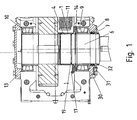
- FIG. 1 is a driven side region of a transmission according to the invention drawn in sectional view.
- FIG. 1a an enlarged section is shown.
- the gear housing, in particular upper and lower side is made of one piece.
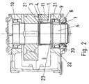
- FIG. 2 is a similar gearbox made of a two-part housing.
- FIG. 3 the attached to the pitot tube 1 piece of sheet metal 4 is shown.
- FIG. 1 a pitot tube 1 is shown, which is provided by means of the O-ring seal 14 in a bore of the gear housing 13 and is sealed to this.
- a bearing 9 of the output shaft 6 is provided on the output side. This bearing 9 is grease-lubricated.
- the pitot tube 1 thus forms together with the transmission housing 13 a trough or a cup-shaped container, in which lubricating oil of the transmission is filled and lubricates the teeth of the transmission.
- a non-contact seal is provided, which is preferably designed as a labyrinth seal.
- a pipe section 2 is pushed onto the output shaft, which has a small distance from the pitot tube 1 in the sealing area.
- this distance range is formed labyrinth-like.
- FIG. 1a a simple variant is shown, in which the seal towards the gear inside and also outwardly comprises a narrow gap, wherein between the two gap regions, a widened region is provided.
- a laminated ring 19 between the output shaft 6 and pitot tube 1 is provided for sealing in an annular groove of the output shaft 6.
- the pipe section 2 also has towards the gear inside a drip edge 12, from which the lubricating oil is abschleuderbar.
- the sheet metal piece 4 is executed substantially flat, as well as in FIG. 1 a and 3 can be seen.
- the filling level of the lubricant bath is at rest lower than the height of the opening portion of the seal.
- a safety distance is maintained, for example, 10 to 100 mm.
- the sheet metal piece 4 at least partially separates the inlet opening, that is, the opening region provided by the gear inside, the seal to adjacent arranged rotatable toothing parts.
- the output side arranged gear of the penultimate stage of the transmission is shown.
- This gear 11 at least partially immersed in the lubricant bath.
- the gear 11 and the meshing with this gear part is lubricated.
- waves or even foam are generated in the lubricating oil bath. The wave height and / or foam height can exceed the height of the inlet opening of the seal.
- the sheet metal piece 4 is arranged between the gearwheel 11 and the output shaft 6, which at least also generate the waves and / or the foam.
- the sheet metal piece derives the waves and the foam from the output shaft, so that the shortest path is blocked by the sheet metal piece 4.
- the sheet metal piece 4 projects beyond the maximum occurring wave height and foam height with its upper edge region.
- the lower end of the shaft piece 4 is provided below the idle oil level level.
- the sheet metal piece 4 is bent twice, as in FIG. 1 clearly to see a offset between a first planar portion of the sheet metal piece and a second portion of the sheet metal piece. This is the drip edge 12 and the paragraph 18 on the same radius providable.
- An advantage of this arrangement is that the distance from the drip edge 12 to the shoulder 18 is easily and clearly measurable during the manufacture of the transmission and thus the pipe section 2 can be arranged relative to the pitot tube 1.
- the sheet metal piece 4 is welded to the pitot tube 1.
- a recess 5 is provided in the sheet metal piece 4, wherein the edge region of the recess 5 is welded connected to the pitot tube 1.
- the welded joint is mounted in the central region of the sheet metal piece 4, so that it does not bend during the welding process.
- the recess 5 is preferably designed as a round hole.
- FIG. 2 shows a top view of the transmission, in which the supply pipe 15 is shown for supplying grease to the area of the grease-lubricated bearing 9.
- a discharge pipe 16 is provided for the discharge of grease from this area.
- This area is formed as it were as a grease chamber and sealed by means of a cover attached to the gear housing 30, which has the shaft sealing ring seats for the shaft seals 7 and 8, and a screwed to this cover 30, the shaft sealing rings covering disc 31.
- a dust lip 32 is provided for protection against coarse protective parts.
- the adjusting device 17 is a position adjustment of the pitot tube 1 executable.
- the adjusting device 17 can be effected, for example, by means of stud bolts provided on the circumference of the pitot tube. It has proven advantageous if three regularly spaced stud bolts are provided on the circumference of the pitot tube.
- the slat ring 19 provided in an annular groove of the output shaft establishes the tightness of the connection between the output shaft 6 and the pitot tube 1.
- FIG. 2 is one after the gearbox FIG. 1 shown similar embodiment, however, the housing is designed in two parts, that is composed of a lower housing part and a housing upper part.
- the sheet metal piece 4 fits during assembly through the bearing 9 receiving bore in the gear housing base 22nd
- an intermediate shaft or the driving shaft with the sealing system according to the invention, comprising the labyrinth seal is used instead of the output shaft.
- the principle is applicable to any emerging from a housing waves.
- the piece of sheet metal instead of substantially planar and preferably designed bent.
- the sheet metal piece of the shape of the gear 11 is approximately trackable.
- the sheet metal piece 4 shields from the gear 11 ago running waves and foam better and the labyrinth seal is even better protectable.
Landscapes
- Engineering & Computer Science (AREA)
- General Engineering & Computer Science (AREA)
- Mechanical Engineering (AREA)
- General Details Of Gearings (AREA)
- Sealing Using Fluids, Sealing Without Contact, And Removal Of Oil (AREA)
- Sealing Devices (AREA)
Description
- Die Erfindung betrifft ein Getriebe.
- Es ist bekannt, bei Getrieben aus dem Getriebegehäuse herausragende Wellen mittels Wellendichtringen abzudichten.
- Aus der
US 4 470 324 A ist ein Getriebe bekannt, aus dem eine Getriebewelle herausragt, die mittels einer berührungslosen Dichtung abgedichtet ist, wobei die zum Getriebeinneren hin gerichtete Öffnung oberhalb des sich bei nicht betriebenem Getriebe einstellenden Schmierölstandes angeordnet ist. - Der Erfindung liegt daher die Aufgabe zugrunde, ein Getriebe weiterzubilden, wobei die Dichtheit gewährleistet sein soll, insbesondere in jeder Einbaulage des Getriebes
- Erfindungsgemäß wird die Aufgabe bei dem Getriebe nach den in Anspruch 1 angegebenen Merkmalen gelöst.
- Wichtige Merkmale der Erfindung bei dem Getriebe sind, dass das Getriebe mit einer vom Getriebeinneren in die Umgebung herausragenden Welle ausgeführt ist, wobei
- die Welle mittels zumindest einer berührungslosen Dichtung abgedichtet ist, wobei die zum Getriebeinneren, also dem das Schmieröl umfassenden Raumbereich des Getriebes, hin gerichtete Öffnung der berührungslosen Dichtung oberhalb des sich bei nicht betriebenem Getriebe einstellenden Schmierölfüllstandes angeordnet ist,
- wobei ein Blechstück zwischen der Öffnung und dem zu dieser Öffnung nächstbenachbarten, aus dem Schmierölbad Schmieröl-Wellen und/oder Schmieröl-Schaum erzeugenden Verzahnungsteil angeordnet ist,
- wobei die berührungslose Dichtung mittels eines auf die Welle aufgeschobenen Rohrstücks und einem mit einem Getrlebegehäuseteil verbundenen Staurohr vorgesehen ist.
- Von Vorteil ist dabei, dass mit zwei einfach herstellbaren Teilen die berührungslose Dichtung herstellbar ist, und dass ein Schutz der Dichtung vor im Betrieb erzeugten Wellen oder erzeugtem Schaum vorsehbar ist. Das Blechstück ist derart ausformbar, dass die erzeugten Wellen die Höhe der Öffnung der Dichtung übertreffen dürfen. Mittels des vorzugsweise noch höher ausgeführten Blechstücks sind die Welle ablenkbar von der Öffnung und werden dann auf dem durch das Blechstück verlängerten Weg stark abgedämpft. Somit ist ein Eintreten von Schmieröl in die berührungslose Dichtung verhinderbar.
- Bei einer vorteilhaften Ausgestaltung ragt die Welle in Gravitationsrichtung nach unten heraus. Von Vorteil ist dabei, dass das Getriebe derart aufstellbar ist, dass die Welle in Gravitationsrichtung nach unten aus dem Getriebegehäuse herausragt und trotzdem Dichtheit gewährleistbar ist.
- Bei einer vorteilhaften Ausgestaltung ist die berührungslose Dichtung eine Labyrinth-Dichtung. Von Vorteil ist dabei, dass eine einfach herstellbare Dichtungsart verwendbar ist, die berührungslos, also verschleißfrei, arbeitet und keine aufwendigen Zusatzteile benötigt.
- Bei einer vorteilhaften Ausgestaltung weist das Rohrstück eine Tropfkante auf, insbesondere die auf gleichem Radius vorgesehen ist wie eine Absatzkante am Staurohr. Von Vorteil ist dabei, dass einerseits ein Abschleudern von Öltropfen ermöglicht ist und gleichzeitig ein einfaches und klares Ablesen des Abstandes ermöglicht ist.
- Bei einer vorteilhaften Ausgestaltung ist das Blechstück schweißverbunden mit dem Staurohr. Von Vorteil ist dabei, dass eine einfach und schnell herstellbare Verbindung verwendbar ist Vorzugsweise ist hierzu ein Loch im Blechstück vorgesehen, an dessen Randbereich die Verschweißung ausgeführt ist.
- Bei einer vorteilhaften Ausgestaltung ist das Blechstück im Wesentlichen eben oder gebogen ausgeführt. Von Vorteil ist dabei, dass bei ebener Ausführung das Blechstück einfach erstellbar ist und bei gebogener Ausführung das Blechstück der Form des Zahnrades der vorhergehenden Stufe anpassbar ist, wodurch eine noch bessere Dämpfung der Wellen und des Schaums ermöglicht ist.
- Bei einer vorteilhaften Ausgestaltung ist zwischen Welle und Rohrstück eine in einer Ringnut vorgesehene Lamellendichtung vorgesehen. Von Vorteil ist dabei, dass das Dichtsystem noch weiter verbessert ist, indem auch zwischen Welle und Rohrstück eine Dichtung vorgesehen ist.
- Bei einer vorteilhaften Ausgestaltung ist eine Einstellvorrichtung zum Einstellen der Lage des Staurohrs vorgesehen. Von Vorteil ist dabei, dass das Staurohr nur eine kurze Auflage im Getriebegehäuse haben darf und trotzdem eine genaue Ausrichtung des Staurohrs ausführbar ist. Vorzugsweise ist die Einstellvorrichtung mittels Stiftschrauben ausgeführt.
- Bei einer vorteilhaften Ausgestaltung ist zwischen Staurohr und Getriebegehäuseunterteil und/oder die Welle lagerndem Lager eine Dichtung vorgesehen, insbesondere O-Ring. Von Vorteil ist dabei, dass das Dichtsystem weiter verbessert ist.
- Bei einer vorteilhaften Ausgestaltung ist am Getriebegehäuseunterteil ein Deckel aufgesetzt und dicht verbunden, der mindestens eine Wellendichtringaufnahme für Wellendichtringe aufweist, wobei die Wellendichtringe die Welle zum Deckel hin abdichten. Von Vorteil ist dabei, dass zusätzlich noch Wellendichtringe vorsehbar sind.
- Bei einer vorteilhaften Ausgestaltung ist am äußeren Bereich der Welle eine Staublippe vorgesehen. Von Vorteil ist dabei, dass
- Bei einer vorteilhaften Ausgestaltung ist ein die Welle im Getriebegehäuse lagerndes Lager in einer Fetikammer vorgesehen oder fettgeschmiert. Von Vorteil ist dabei, dass
- Bei einer vorteilhaften Ausgestaltung sind ein Zuleitungsrohr für Fett zum Lager hin und ein Ableitungsrohr für Fett vorgesehen. Von Vorteil ist dabei, dass
- Bei einer vorteilhaften Ausgestaltung ist das Getriebegehäuse einstückig oder als Unterteil und Oberteil ausgeführt. Von Vorteil ist dabei, dass
- Weitere Vorteile ergeben sich aus den Unteransprüchen.
-
- 1
- Staurohr
- 2
- Rohrstück
- 3
- Labyrinth-Dichtung
- 4
- Blechstück
- 5
- im Blech vorgesehene Ausnehmung zum Herstellen einer Schweißverbindung
- 6
- Abtriebswelle
- 7
- Wellendichtring
- 8
- Wellendichtring
- 9
- abtriebsseitiges Lager der Abtriebswelle
- 10
- zweites Lager der Abtriebswelle
- 11
- abtreibendes Zahnrad der vorletzten Stufe des Getriebes
- 12
- Tropfkante
- 13
- Getriebegehäuse
- 14
- O-Ring-Dichtung
- 15
- Zuleitungsrohr für Fett
- 16
- Ableitungsrohr für Fett
- 17
- Einstellvorrichtung
- 18
- Absatz
- 19
- Lamellenring
- 20
- Staurohr
- 21
- O-Ring-Dichtung
- 22
- Getriebegehäuseunterteil
- 23
- Lamellenring
- 30
- Deckel
- 31
- Scheibe, aufgeschraubt auf Deckel 30
- 32
- Staublippe
- Die Erfindung wird nun anhand von Abbildungen näher erläutert:
- In der
Figur 1 ist ein abtriebsseitiger Bereich eines erfindungsgemäßen Getriebes in Schnittansicht gezeichnet. InFigur 1a ist ein vergrößerter Ausschnitt dargestellt. Dabei ist das Getriebegehäuse, insbesondere obere und untere Seite aus einem Stück gefertigt. - In
Figur 2 ist ein ähnliches Getriebe aus einem zweigeteilten Gehäuse gefertigt. - In
Figur 3 ist das am Staurohr 1 befestigte Blechstück 4 gezeigt. - In der
Figur 1 ist ein Staurohr 1 gezeigt, das mittels der O-Ring-Dichtung 14 in einer Bohrung des Getriebegehäuses 13 vorgesehen und mit diesem dicht verbunden ist. - Ein Lager 9 der Abtriebswelle 6 ist abtriebsseitig vorgesehen. Dieses Lager 9 ist fettgeschmiert.
- Das Staurohr 1 bildet somit zusammen mit dem Getriebegehäuse 13 eine Wanne oder einen schalenförmigen Behälter, in welchen Schmieröl des Getriebes eingefüllt ist und die Verzahnungsteile des Getriebes schmiert.
- Zur in den Lagern 9 und 10 gelagerten Abtriebswelle 6 hin ist eine berührungsfreie Dichtung vorgesehen, die vorzugsweise als Labyrinth-Dichtung ausgeführt ist. Hierzu ist auf die Abtriebswelle ein Rohrstück 2 aufgeschoben, das im Dichtungsbereich einen geringen Abstand zum Staurohr 1 hin aufweist. Bei Ausführung der Labyrinth-Dichtung ist dieser Abstandsbereich labyrinthartig ausgeformt. In
Figur 1a ist eine einfache Variante gezeigt, bei der die Dichtung zum Getriebeinneren hin und auch nach außen einen schmalen Spalt umfasst, wobei zwischen den beiden Spaltbereichen ein aufgeweiteter Bereich vorgesehen ist. - Zur weiteren Abdichtung der nach unten, also in Gravitationsrichtung aus dem Getriebegehäuse austretenden Abtriebswelle gegen das Getriebegehäuse sind noch zwei weitere hintereinander angeordnete Wellendichtringe 7 und 8 vorgesehen.
- Außerdem ist ein Lamellenring 19 zwischen Abtriebswelle 6 und Staurohr 1 zur Abdichtung in einer Ringnut der Abtriebswelle 6 vorgesehen.
- Das Rohrstück 2 weist auch zum Getriebeinneren hin eine Tropfkante 12 auf, von der das Schmieröl abschleuderbar ist.
- Das Blechstück 4 ist im Wesentlichen eben ausgeführt, wie auch in
Figur 1 a und 3 ersichtlich ist. - Die Füllhöhe des Schmierstoffbades ist im Ruhezustand niedriger als die Höhe des Öffnungsbereiches der Dichtung. Vorzugsweise ist ein Sicherheitsabstand eingehalten von beispielsweise 10 bis 100 mm.
- Wichtig ist dabei, dass das Blechstück 4 die Eintrittsöffnung, also der vom Getriebeinneren aus vorgesehene Öffnungsbereich, der Dichtung zu benachbart angeordneten drehbaren Verzahnungsteilen zumindest teilweise abtrennt. In der
Figur 1 ist hierzu das abtriebsseitig angeordnete Zahnrad der vorletzten Stufe des Getriebes dargestellt. Dieses Zahnrad 11 taucht zumindest teilweise ins Schmierstoffbad ein. Wenn dieses in Drehbewegung versetzt ist, wird das Zahnrad 11 und das mit diesem in Eingriff stehende Verzahnungsteil geschmiert. Außerdem werden im Schmierölbad Wellen oder gar Schaum erzeugt. Die Wellenhöhe und/oder Schaumhöhe können hierbei die Höhe der Eintrittsöffnung der Dichtung übertreffen. - Das Blechstück 4 ist jedoch zwischen dem die Wellen und/oder den Schaum zumindest auch erzeugenden Zahnrad 11 und der Abtriebswelle 6 angeordnet. Dabei leitet das Blechstück die Wellen und den Schaum ab von der Abtriebswelle, so dass der kürzeste Weg mittels des Blechstücks 4 versperrt ist. Vorzugsweise überragt das Blechstück 4 mit seinem oberen Randbereich die maximal auftretende Wellenhöhe und Schaumhöhe. Das untere Ende des Wellenstücks 4 ist unterhalb der im Ruhezustand vorhandenen Schmierölfüllstandshöhe vorgesehen.
- Vorzugsweise ist das Blechstück 4 zweifach gebogen, wie in
Figur 1 a und 3 deutlich zu sehen, um einen Versatz zwischen einem ersten ebenen Teilbereich des Blechstücks und einem zweiten Teilbereich des Blechstücks zu erzeugen. Auf diese Weise ist die Tropfkante 12 und der Absatz 18 auf dem gleichen Radius vorsehbar. Ein Vorteil dieser Anordnung ist, dass der Abstand von der Tropfkante 12 zum Absatz 18 einfach und klar messbar ist beim Herstellen des Getriebes und somit das Rohrstück 2 relativ zum Staurohr 1 anordenbar ist. - Das Blechstück 4 ist am Staurohr 1 angeschweißt. Hierzu ist eine Ausnehmung 5 im Blechstück 4 vorgesehen, wobei der Randbereich der Ausnehmung 5 schweißverbunden wird mit dem Staurohr 1. Die Schweißverbindung ist im mittleren Bereich des Blechstücks 4 angebracht, so dass dieses sich nicht verbiegt beim Schweißvorgang. Die Ausnehmung 5 ist vorzugsweise als rundes Loch ausgeführt.
- In
Figur 1b ist eine Draufsicht auf das Getriebe gezeigt, bei der das Zuleitungsrohr 15 für das Zuleiten von Fett in den Bereich des fettgeschmierten Lagers 9 gezeigt ist. Um Überdruck zu Vermeiden ist ein Ableitungsrohr 16 für das Herausleiten von Fett aus diesem Bereich vorgesehen. Dieser Bereich ist sozusagen als Fettkammer ausgebildet und mittels eines am Getriebegehäuse aufgesetzten Deckels 30, der die Wellendichtringsitze für die Wellendichtringe 7 und 8 aufweist, und einer an diesen Deckel 30 angeschraubten, die Wellendichtringe abdeckenden Scheibe 31 abgedichtet. Zusätzlich ist noch außerhalb der Scheibe 31 eine Staublippe 32 zum Schutz gegen grobe Schutzteile vorgesehen. - Mittels der Einstellvorrichtung 17 ist eine Lageeinstellung des Staurohrs 1 ausführbar. Die Einstellvorrichtung 17 ist beispielsweise mittels am Umfang des Staurohrs vorgesehenen Stiftschrauben bewirkbar. Vorteilhaft hat sich erwiesen, wenn am Umfang des Staurohrs drei regelmäßig voneinander beabstandete Stiftschrauben vorgesehen werden.
- Der in einer Ringnut der Abtriebswelle vorgesehene Lamellenring 19 stellt die Dichtheit der Verbindung zwischen Abtriebswelle 6 und Staurohr 1 her.
- In der
Figur 2 ist eine zum Getriebe nachFigur 1 ähnliche Ausführung gezeigt, wobei allerdings das Gehäuse zweigeteilt ausgeführt ist, also aus einem Gehäuseunterteil und einem Gehäuseoberteil zusammengesetzt ist. - Auch ist bei
Figur 2 die Verbindung vom Lager 9 zum Staurohr 20 mittels der O-Ring-Dichtung 21 und vom Staurohr 20 zur Abtriebswelle 6 mittels des Lamellenrings 23 abgedichtet. - Da jedoch die Führung des Staurohrs 20 am Getriebegehäuseunterteil 22 axial länger ausführbar ist, ist keine Einstellvorrichtung 17 notwendig.
- Das Blechstück 4 passt bei Montage durch die das Lager 9 aufnehmende Bohrung im Getriebegehäuseunterteil 22.
- Bei weiteren erfindungsgemäßen Ausführungsbeispielen wird statt der Abtriebswelle eine Zwischenwelle oder die eintreibende Welle mit dem erfindungsgemäßen Dichtsystem, umfassend die Labyrinthdichtung, verwendet. Auch ist das Prinzip auf beliebige aus einem Gehäuse heraustretenden Wellen anwendbar.
- Bei weiteren erfindungsgemäßen Ausführungsbeispielen ist das Blechstück anstatt im Wesentlichen eben vorzugsweise gebogen ausgeführt. Somit ist das Blechstück der Form des Zahnrades 11 in etwa nachführbar. Somit schirmt das Blechstück 4 vom Zahnrad 11 her verlaufende Wellen und Schaum besser ab und die Labyrinthdichtung ist noch besser schützbar.
Claims (14)
- Getriebe mit einer vom Getriebeinneren In die Umgebung herausragenden Welle,
wobei die Welle mittels zumindest einer berührungslosen Dichtung abgedichtet ist, wobei die zum Getriebeinneren, also dem das Schmieröl umfassenden Raumbereich des Getriebes, hin gerichtete Öffnung der berührungslosen Dichtung oberhalb des sich bei nicht betriebenem Getriebe einstellenden Schmlerölfüllstandes angeordnet ist,
dadurch gekennzeichnet, dass
ein Blechstück (4) zwischen der Öffnung und dem zu dieser Öffnung nächstbenachbarten, aus dem Schmierölbad Schmieröl-Wellen und/oder Schmieröl-Schaum erzeugenden Verzahnungstell angeordnet ist,
wobei die berührungslose Dichtung mittel eines auf die Welle aufgeschobenen Rohrstücks (2) und einem mit einem Getriebegehäuseteil verbundenen Staurohr (1) vorgesehen ist. - Getriebe nach Anspruch 1,
dadurch gekennzeichnet, dass
die Welle in Gravitationsrichtung nach unten herausragt. - Getriebe nach mindestens einem der vorangegangenen Ansprüche,
dadurch gekennzeichnet, dass
die berührungslose Dichtung eine Labyrinth-Dichtung (3) ist - Getriebe nach mindestens einem der vorangegangenen Ansprüche,
dadurch gekennzeichnet, dass
das Rohrstück (2) eine Tropfkante (12) aufweist, insbesondere die auf gleichem Radius vorgesehen ist wie eine Absatzkante am Staurohr (1). - Getriebe nach mindestens einem der vorangegangenen Ansprüche,
dadurch gekennzeichnet, dass
das Blechstück (4) schweißverbunden ist mit dem Staurohr (1). - Getriebe nach mindestens einem der vorangegangenen Ansprüche,
dadurch gekennzeichnet, dass
das Blechstück (4) im Wesentlichen eben oder gebogen ausgeführt ist - Getriebe nach mindestens einem der vorangegangenen Ansprüche,
dadurch gekennzeichnet, dass
zwischen Welle und Rohrstück (2) eine in einer Ringnut vorgesehene Lamellendichtung vorgesehen ist. - Getriebe nach mindestens einem der vorangegangenen Ansprüche,
dadurch gekennzeichnet, dass
eine Einstellvorrichtung zum Einstellen der Lage des Staurohrs (1) vorgesehen ist. - Getriebe nach mindestens einem der vorangegangenen Ansprüche,
dadurch gekennzeichnet, dass
zwischen Staurohr (1) und Getriebegehäuseunterteil (22) und/oder die Welle lagerndem Lager (9) eine Dichtung vorgesehen ist, insbesondere O-Ring. - Getriebe nach mindestens einem der vorangegangenen Ansprüche,
dadurch gekennzeichnet, dass
am Getriebegehäuseuntertell (22) ein Deckel aufgesetzt und dicht verbunden ist, der mindestens eine Wellendichtringaufnahme für Wellendichtringe (7, 8) aufweist, wobei die Wellendichtringe (7, 8) die Welle zum Deckel hin abdichten. - Getriebe nach mindestens einem der vorangegangenen Ansprüche,
dadurch gekennzeichnet, dass
am äußeren Bereich der Welle eine Staublippe vorgesehen ist. - Getriebe nach mindestens einem der vorangegangenen Ansprüche,
dadurch gekennzeichnet, dass
ein die Welle im Getriebegehäuse (13) lagerndes Lager (9) in einer Fettkammer vorgesehen ist oder fettgeschmiert ist. - Getriebe nach mindestens einem der vorangegangenen Ansprüche,
dadurch gekennzeichnet, dass
ein Zuleitungsrohr für Fett zum Lager (9) hin und ein Ableitungsrohr für Fett vorgesehen sind. - Getriebe nach mindestens einem der vorangegangenen Ansprüche,
dadurch gekennzeichnet, dass
das Getriebegehäuse (13) einstückig oder als Unterteil und Oberteil ausgeführt ist.
Applications Claiming Priority (2)
| Application Number | Priority Date | Filing Date | Title |
|---|---|---|---|
| DE102008034414A DE102008034414B4 (de) | 2008-07-23 | 2008-07-23 | Getriebe |
| PCT/EP2009/005312 WO2010009871A1 (de) | 2008-07-23 | 2009-07-22 | Getriebe |
Publications (3)
| Publication Number | Publication Date |
|---|---|
| EP2318734A1 EP2318734A1 (de) | 2011-05-11 |
| EP2318734B1 true EP2318734B1 (de) | 2012-09-19 |
| EP2318734B2 EP2318734B2 (de) | 2016-02-24 |
Family
ID=41152130
Family Applications (1)
| Application Number | Title | Priority Date | Filing Date |
|---|---|---|---|
| EP09777359.2A Active EP2318734B2 (de) | 2008-07-23 | 2009-07-22 | Getriebe |
Country Status (10)
| Country | Link |
|---|---|
| US (2) | US9360102B2 (de) |
| EP (1) | EP2318734B2 (de) |
| CN (1) | CN102105725B (de) |
| AU (1) | AU2009273450B2 (de) |
| BR (1) | BRPI0916838B1 (de) |
| CA (1) | CA2731876C (de) |
| DE (1) | DE102008034414B4 (de) |
| EA (1) | EA021098B1 (de) |
| WO (1) | WO2010009871A1 (de) |
| ZA (1) | ZA201100998B (de) |
Families Citing this family (10)
| Publication number | Priority date | Publication date | Assignee | Title |
|---|---|---|---|---|
| DE102008034414B4 (de) * | 2008-07-23 | 2011-01-27 | Sew-Eurodrive Gmbh & Co. Kg | Getriebe |
| CN102359575A (zh) * | 2011-10-21 | 2012-02-22 | 南京大洋冷却塔股份有限公司 | 一种冷却塔用减速器 |
| DE102012000666B4 (de) * | 2012-01-17 | 2021-06-10 | Sew-Eurodrive Gmbh & Co Kg | Getriebe mit einer vom Getriebeinneren in die Umgebung herausragenden Welle |
| DE102013018713B4 (de) | 2013-11-08 | 2025-10-02 | Sew-Eurodrive Gmbh & Co Kg | Getriebe mit Gehäuse |
| US9879771B2 (en) * | 2015-03-27 | 2018-01-30 | Amarillo Gear Company Llc | Dry well shaft assembly |
| RU2622329C1 (ru) * | 2016-06-28 | 2017-06-14 | Николай Викторович Мендрух | Зубчатый редуктор |
| JP6394670B2 (ja) * | 2016-10-06 | 2018-09-26 | トヨタ自動車株式会社 | 車両用動力伝達装置 |
| DE102016012501C5 (de) * | 2016-10-19 | 2022-08-04 | Sew-Eurodrive Gmbh & Co Kg | Getriebe, aufweisend eine Welle, ein Gehäuseteil und ein Adaptergehäuse |
| CN108757903B (zh) * | 2018-05-21 | 2019-10-15 | 江苏微特利电机股份有限公司 | 一种用于新能源汽车的减速电机 |
| CN108953567A (zh) * | 2018-08-02 | 2018-12-07 | 湖南南方宇航高精传动有限公司 | 一种带有除气泡迷宫密封结构的齿轮箱 |
Family Cites Families (30)
| Publication number | Priority date | Publication date | Assignee | Title |
|---|---|---|---|---|
| DE154729C (de) | ||||
| US1810372A (en) * | 1928-10-09 | 1931-06-16 | Westinghouse Electric & Mfg Co | Labyrinth packing |
| US2075532A (en) * | 1930-08-04 | 1937-03-30 | Us Electrical Motors Inc | Oiling device |
| DE617253C (de) † | 1931-07-18 | 1935-08-15 | Siemens Schuckertwerke Akt Ges | Mehrfachlager mit Umlaufschmierung fuer stehende Wellen |
| US2485537A (en) † | 1945-05-16 | 1949-10-18 | Falk Corp | Liquid sealed trap |
| FR1057778A (fr) * | 1950-05-08 | 1954-03-10 | Dispositif de protection et de lubrification des roulements et paliers | |
| US2955001A (en) † | 1957-12-30 | 1960-10-04 | Morgan Construction Co | Bearing |
| US3214989A (en) * | 1963-04-01 | 1965-11-02 | Falk Corp | Vertical right angle speed reducer |
| US3276289A (en) * | 1964-07-17 | 1966-10-04 | Abex Corp | Gear case |
| US3704960A (en) * | 1971-02-26 | 1972-12-05 | Wilfley & Sons Inc A | Vertical centrifugal pump |
| DE3141061A1 (de) † | 1981-10-13 | 1983-04-28 | Siemens AG, 1000 Berlin und 8000 München | Selbstpumpendes spurlager fuer elektrische maschinen mit vertikaler welle, insbesondere wasserkraftgeneratoren |
| US4470324A (en) * | 1981-10-19 | 1984-09-11 | Carol A. MacKay | Gear case |
| JPS6111423A (ja) * | 1984-06-28 | 1986-01-18 | Taiho Kogyo Co Ltd | タ−ボチヤ−ジヤ用非接触型シ−ル装置 |
| US4683985A (en) * | 1985-01-04 | 1987-08-04 | Dresser Industries, Inc. | Lubrication system for a vertical gear unit |
| KR950008505B1 (ko) * | 1985-11-04 | 1995-07-31 | 카롤 앤 맥키 | 윤활유 제한장치 |
| DE3617863A1 (de) * | 1986-05-27 | 1987-12-03 | Mueller Heinz Konrad Prof Dr I | Spritzring-labyrinthdichtung |
| WO1995001524A1 (en) * | 1993-06-30 | 1995-01-12 | Twentieth Technology | Low-leakage and low-instability labyrinth seal |
| US5676221A (en) * | 1996-06-06 | 1997-10-14 | Carol Ann Mackay | Gear case |
| DE19855970C2 (de) * | 1998-12-04 | 2003-08-14 | Zahnradfabrik Friedrichshafen | Vorrichtung zur Zwischenspeicherung von Öl |
| US6058793A (en) * | 1999-01-19 | 2000-05-09 | Chemineer, Inc. | Parallel shaft speed reducer with sump and dry well |
| US6347708B1 (en) * | 1999-03-22 | 2002-02-19 | Cedarapids Inc. | Wheel case for a vibratory apparatus |
| JP4650913B2 (ja) * | 2000-04-27 | 2011-03-16 | 株式会社ハーモニック・ドライブ・システムズ | 中空型波動歯車装置の潤滑剤漏れ防止機構 |
| DE102004016173A1 (de) * | 2004-03-30 | 2005-10-20 | Alstom Technology Ltd Baden | Lamellendichtung, insbesondere für eine Gasturbine, sowie Verfahren zu deren Herstellung |
| DE102004036333B4 (de) * | 2004-07-27 | 2007-08-30 | Audi Ag | Kegelrad-Differenzial für Kraftfahrzeuge |
| US20060196304A1 (en) * | 2005-02-22 | 2006-09-07 | Konruff Michael E | Inverted oil pan mounting for mono-block housings |
| DE102006044964A1 (de) * | 2006-09-22 | 2008-04-03 | Siemens Ag | Getriebeeinheit, Antrieb mit einer derartigen Getriebeeinheit, Elektromotor zum Antrieb eines Fahrzeuges sowie Verwendung eines derartigen Antriebs und Elektromotors |
| DE102007059406A1 (de) * | 2006-12-21 | 2008-06-26 | Luk Lamellen Und Kupplungsbau Beteiligungs Kg | Integrale Lippendichtung zum Schutz gegen Verunreinigungen durch Schweissen |
| JP5006691B2 (ja) * | 2007-04-27 | 2012-08-22 | 住友重機械工業株式会社 | ハイポイドギヤモータ及びその製造方法 |
| DE102008034414B4 (de) * | 2008-07-23 | 2011-01-27 | Sew-Eurodrive Gmbh & Co. Kg | Getriebe |
| JP6647036B2 (ja) * | 2015-12-24 | 2020-02-14 | オリンパス株式会社 | ウェアラブル装置 |
-
2008
- 2008-07-23 DE DE102008034414A patent/DE102008034414B4/de active Active
-
2009
- 2009-07-22 WO PCT/EP2009/005312 patent/WO2010009871A1/de not_active Ceased
- 2009-07-22 EA EA201170247A patent/EA021098B1/ru not_active IP Right Cessation
- 2009-07-22 AU AU2009273450A patent/AU2009273450B2/en active Active
- 2009-07-22 US US13/054,711 patent/US9360102B2/en active Active
- 2009-07-22 EP EP09777359.2A patent/EP2318734B2/de active Active
- 2009-07-22 BR BRPI0916838A patent/BRPI0916838B1/pt active IP Right Grant
- 2009-07-22 CA CA2731876A patent/CA2731876C/en active Active
- 2009-07-22 CN CN2009801284718A patent/CN102105725B/zh active Active
-
2011
- 2011-02-08 ZA ZA2011/00998A patent/ZA201100998B/en unknown
-
2016
- 2016-06-06 US US15/174,374 patent/US10718421B2/en active Active
Also Published As
| Publication number | Publication date |
|---|---|
| EA201170247A1 (ru) | 2011-08-30 |
| DE102008034414B4 (de) | 2011-01-27 |
| EP2318734B2 (de) | 2016-02-24 |
| CA2731876A1 (en) | 2010-01-28 |
| CN102105725A (zh) | 2011-06-22 |
| CA2731876C (en) | 2016-12-06 |
| CN102105725B (zh) | 2013-06-19 |
| AU2009273450A1 (en) | 2010-01-28 |
| US10718421B2 (en) | 2020-07-21 |
| WO2010009871A1 (de) | 2010-01-28 |
| EP2318734A1 (de) | 2011-05-11 |
| DE102008034414A1 (de) | 2010-02-04 |
| AU2009273450B2 (en) | 2013-05-23 |
| EA021098B1 (ru) | 2015-04-30 |
| BRPI0916838B1 (pt) | 2019-02-05 |
| US9360102B2 (en) | 2016-06-07 |
| ZA201100998B (en) | 2012-02-29 |
| US20110146437A1 (en) | 2011-06-23 |
| US20180119791A1 (en) | 2018-05-03 |
Similar Documents
| Publication | Publication Date | Title |
|---|---|---|
| EP2318734B2 (de) | Getriebe | |
| EP3948027B1 (de) | Getriebe und verfahren zum herstellen unterschiedlicher getriebe, insbesondere einer getriebebaureihe | |
| DE112014001512B4 (de) | Hohles Verformungswellgetriebe und hohler Aktuator | |
| DE102013018710B4 (de) | Getriebe mit Gehäuse | |
| EP3371487B1 (de) | Getriebe mit aus einem unterteil und einem oberteil gebildeten, teilweise mit öl befüllten gehäuse und mit einem zahnrad | |
| EP3066366B1 (de) | Getriebe mit gehäuse | |
| EP2805088B1 (de) | Getriebe | |
| EP3066364B1 (de) | Getriebe mit gehäuse | |
| EP3066365A1 (de) | Getriebe mit gehäuse | |
| DE102022003369A1 (de) | Getriebe mit einem Gehäuseteil und einem Deckel | |
| DE19937396C2 (de) | Aufnahme-Vorrichtung für mehrere Wälzlager | |
| EP4176184A2 (de) | Getriebe mit einer welle und einem gehäuseteil | |
| EP2946132A1 (de) | Antrieb | |
| DE102017000304B3 (de) | Antrieb, aufweisend von Elektromotoren angetriebenes Summiergetriebe und ein von diesem angetriebenes Getriebe | |
| DE10233509A1 (de) | Getriebegehäuse | |
| DE102013013976B4 (de) | Getriebemotor | |
| EP4490417B1 (de) | Getriebe mit gehäuseteil und lager zur drehbaren lagerung einer welle | |
| EP3382353B1 (de) | Anzeigeeinrichtung für die visuelle kontrolle eines flüssigkeitsfüllstands insbesondere in einem getriebe | |
| WO2020074118A1 (de) | Getriebe mit getriebegehäuse | |
| DE112013006352T5 (de) | Anordnung zum Schmieren eines Achsdifferenzials | |
| EP3563069B1 (de) | Welle mit einer abspritzkante zum abführen entlang der welle eindringenden schmiermittels mittels fliehkraft | |
| DE102017126078B4 (de) | Getriebe für einen elektrischen Radantrieb eines Fahrzeugs | |
| DE102012213962A1 (de) | Lageranordnung | |
| DE102014009316B3 (de) | Getriebe | |
| WO2025131478A1 (de) | Getriebe mit gehäuse |
Legal Events
| Date | Code | Title | Description |
|---|---|---|---|
| PUAI | Public reference made under article 153(3) epc to a published international application that has entered the european phase |
Free format text: ORIGINAL CODE: 0009012 |
|
| 17P | Request for examination filed |
Effective date: 20110223 |
|
| AK | Designated contracting states |
Kind code of ref document: A1 Designated state(s): AT BE BG CH CY CZ DE DK EE ES FI FR GB GR HR HU IE IS IT LI LT LU LV MC MK MT NL NO PL PT RO SE SI SK SM TR |
|
| AX | Request for extension of the european patent |
Extension state: AL BA RS |
|
| DAX | Request for extension of the european patent (deleted) | ||
| GRAP | Despatch of communication of intention to grant a patent |
Free format text: ORIGINAL CODE: EPIDOSNIGR1 |
|
| GRAS | Grant fee paid |
Free format text: ORIGINAL CODE: EPIDOSNIGR3 |
|
| GRAA | (expected) grant |
Free format text: ORIGINAL CODE: 0009210 |
|
| AK | Designated contracting states |
Kind code of ref document: B1 Designated state(s): AT BE BG CH CY CZ DE DK EE ES FI FR GB GR HR HU IE IS IT LI LT LU LV MC MK MT NL NO PL PT RO SE SI SK SM TR |
|
| REG | Reference to a national code |
Ref country code: GB Ref legal event code: FG4D Free format text: NOT ENGLISH |
|
| REG | Reference to a national code |
Ref country code: CH Ref legal event code: EP |
|
| REG | Reference to a national code |
Ref country code: IE Ref legal event code: FG4D Free format text: LANGUAGE OF EP DOCUMENT: GERMAN |
|
| REG | Reference to a national code |
Ref country code: AT Ref legal event code: REF Ref document number: 576207 Country of ref document: AT Kind code of ref document: T Effective date: 20121015 |
|
| REG | Reference to a national code |
Ref country code: DE Ref legal event code: R096 Ref document number: 502009004829 Country of ref document: DE Effective date: 20121115 |
|
| PG25 | Lapsed in a contracting state [announced via postgrant information from national office to epo] |
Ref country code: HR Free format text: LAPSE BECAUSE OF FAILURE TO SUBMIT A TRANSLATION OF THE DESCRIPTION OR TO PAY THE FEE WITHIN THE PRESCRIBED TIME-LIMIT Effective date: 20120919 Ref country code: LT Free format text: LAPSE BECAUSE OF FAILURE TO SUBMIT A TRANSLATION OF THE DESCRIPTION OR TO PAY THE FEE WITHIN THE PRESCRIBED TIME-LIMIT Effective date: 20120919 Ref country code: NO Free format text: LAPSE BECAUSE OF FAILURE TO SUBMIT A TRANSLATION OF THE DESCRIPTION OR TO PAY THE FEE WITHIN THE PRESCRIBED TIME-LIMIT Effective date: 20121219 Ref country code: FI Free format text: LAPSE BECAUSE OF FAILURE TO SUBMIT A TRANSLATION OF THE DESCRIPTION OR TO PAY THE FEE WITHIN THE PRESCRIBED TIME-LIMIT Effective date: 20120919 |
|
| REG | Reference to a national code |
Ref country code: NL Ref legal event code: VDEP Effective date: 20120919 |
|
| REG | Reference to a national code |
Ref country code: LT Ref legal event code: MG4D Effective date: 20120919 |
|
| PG25 | Lapsed in a contracting state [announced via postgrant information from national office to epo] |
Ref country code: SI Free format text: LAPSE BECAUSE OF FAILURE TO SUBMIT A TRANSLATION OF THE DESCRIPTION OR TO PAY THE FEE WITHIN THE PRESCRIBED TIME-LIMIT Effective date: 20120919 Ref country code: LV Free format text: LAPSE BECAUSE OF FAILURE TO SUBMIT A TRANSLATION OF THE DESCRIPTION OR TO PAY THE FEE WITHIN THE PRESCRIBED TIME-LIMIT Effective date: 20120919 Ref country code: SE Free format text: LAPSE BECAUSE OF FAILURE TO SUBMIT A TRANSLATION OF THE DESCRIPTION OR TO PAY THE FEE WITHIN THE PRESCRIBED TIME-LIMIT Effective date: 20120919 Ref country code: GR Free format text: LAPSE BECAUSE OF FAILURE TO SUBMIT A TRANSLATION OF THE DESCRIPTION OR TO PAY THE FEE WITHIN THE PRESCRIBED TIME-LIMIT Effective date: 20121220 |
|
| PG25 | Lapsed in a contracting state [announced via postgrant information from national office to epo] |
Ref country code: RO Free format text: LAPSE BECAUSE OF FAILURE TO SUBMIT A TRANSLATION OF THE DESCRIPTION OR TO PAY THE FEE WITHIN THE PRESCRIBED TIME-LIMIT Effective date: 20120919 Ref country code: EE Free format text: LAPSE BECAUSE OF FAILURE TO SUBMIT A TRANSLATION OF THE DESCRIPTION OR TO PAY THE FEE WITHIN THE PRESCRIBED TIME-LIMIT Effective date: 20120919 Ref country code: NL Free format text: LAPSE BECAUSE OF FAILURE TO SUBMIT A TRANSLATION OF THE DESCRIPTION OR TO PAY THE FEE WITHIN THE PRESCRIBED TIME-LIMIT Effective date: 20120919 Ref country code: IS Free format text: LAPSE BECAUSE OF FAILURE TO SUBMIT A TRANSLATION OF THE DESCRIPTION OR TO PAY THE FEE WITHIN THE PRESCRIBED TIME-LIMIT Effective date: 20130119 Ref country code: CZ Free format text: LAPSE BECAUSE OF FAILURE TO SUBMIT A TRANSLATION OF THE DESCRIPTION OR TO PAY THE FEE WITHIN THE PRESCRIBED TIME-LIMIT Effective date: 20120919 Ref country code: ES Free format text: LAPSE BECAUSE OF FAILURE TO SUBMIT A TRANSLATION OF THE DESCRIPTION OR TO PAY THE FEE WITHIN THE PRESCRIBED TIME-LIMIT Effective date: 20121230 |
|
| PG25 | Lapsed in a contracting state [announced via postgrant information from national office to epo] |
Ref country code: SK Free format text: LAPSE BECAUSE OF FAILURE TO SUBMIT A TRANSLATION OF THE DESCRIPTION OR TO PAY THE FEE WITHIN THE PRESCRIBED TIME-LIMIT Effective date: 20120919 Ref country code: PT Free format text: LAPSE BECAUSE OF FAILURE TO SUBMIT A TRANSLATION OF THE DESCRIPTION OR TO PAY THE FEE WITHIN THE PRESCRIBED TIME-LIMIT Effective date: 20130121 Ref country code: PL Free format text: LAPSE BECAUSE OF FAILURE TO SUBMIT A TRANSLATION OF THE DESCRIPTION OR TO PAY THE FEE WITHIN THE PRESCRIBED TIME-LIMIT Effective date: 20120919 |
|
| PLBI | Opposition filed |
Free format text: ORIGINAL CODE: 0009260 |
|
| PLAX | Notice of opposition and request to file observation + time limit sent |
Free format text: ORIGINAL CODE: EPIDOSNOBS2 |
|
| 26 | Opposition filed |
Opponent name: SIEMENS AKTIENGESELLSCHAFT Effective date: 20130619 |
|
| PG25 | Lapsed in a contracting state [announced via postgrant information from national office to epo] |
Ref country code: BG Free format text: LAPSE BECAUSE OF FAILURE TO SUBMIT A TRANSLATION OF THE DESCRIPTION OR TO PAY THE FEE WITHIN THE PRESCRIBED TIME-LIMIT Effective date: 20121219 Ref country code: DK Free format text: LAPSE BECAUSE OF FAILURE TO SUBMIT A TRANSLATION OF THE DESCRIPTION OR TO PAY THE FEE WITHIN THE PRESCRIBED TIME-LIMIT Effective date: 20120919 |
|
| REG | Reference to a national code |
Ref country code: DE Ref legal event code: R026 Ref document number: 502009004829 Country of ref document: DE Effective date: 20130619 |
|
| PLAF | Information modified related to communication of a notice of opposition and request to file observations + time limit |
Free format text: ORIGINAL CODE: EPIDOSCOBS2 |
|
| PG25 | Lapsed in a contracting state [announced via postgrant information from national office to epo] |
Ref country code: CY Free format text: LAPSE BECAUSE OF FAILURE TO SUBMIT A TRANSLATION OF THE DESCRIPTION OR TO PAY THE FEE WITHIN THE PRESCRIBED TIME-LIMIT Effective date: 20120919 |
|
| PLBB | Reply of patent proprietor to notice(s) of opposition received |
Free format text: ORIGINAL CODE: EPIDOSNOBS3 |
|
| BERE | Be: lapsed |
Owner name: SEW-EURODRIVE G.M.B.H. & CO Effective date: 20130731 |
|
| PG25 | Lapsed in a contracting state [announced via postgrant information from national office to epo] |
Ref country code: MC Free format text: LAPSE BECAUSE OF FAILURE TO SUBMIT A TRANSLATION OF THE DESCRIPTION OR TO PAY THE FEE WITHIN THE PRESCRIBED TIME-LIMIT Effective date: 20120919 |
|
| REG | Reference to a national code |
Ref country code: CH Ref legal event code: PL |
|
| REG | Reference to a national code |
Ref country code: IE Ref legal event code: MM4A |
|
| PG25 | Lapsed in a contracting state [announced via postgrant information from national office to epo] |
Ref country code: BE Free format text: LAPSE BECAUSE OF NON-PAYMENT OF DUE FEES Effective date: 20130731 Ref country code: LI Free format text: LAPSE BECAUSE OF NON-PAYMENT OF DUE FEES Effective date: 20130731 Ref country code: CH Free format text: LAPSE BECAUSE OF NON-PAYMENT OF DUE FEES Effective date: 20130731 |
|
| PG25 | Lapsed in a contracting state [announced via postgrant information from national office to epo] |
Ref country code: IE Free format text: LAPSE BECAUSE OF NON-PAYMENT OF DUE FEES Effective date: 20130722 |
|
| PG25 | Lapsed in a contracting state [announced via postgrant information from national office to epo] |
Ref country code: SM Free format text: LAPSE BECAUSE OF FAILURE TO SUBMIT A TRANSLATION OF THE DESCRIPTION OR TO PAY THE FEE WITHIN THE PRESCRIBED TIME-LIMIT Effective date: 20120919 |
|
| REG | Reference to a national code |
Ref country code: FR Ref legal event code: PLFP Year of fee payment: 7 |
|
| PG25 | Lapsed in a contracting state [announced via postgrant information from national office to epo] |
Ref country code: TR Free format text: LAPSE BECAUSE OF FAILURE TO SUBMIT A TRANSLATION OF THE DESCRIPTION OR TO PAY THE FEE WITHIN THE PRESCRIBED TIME-LIMIT Effective date: 20120919 Ref country code: MT Free format text: LAPSE BECAUSE OF FAILURE TO SUBMIT A TRANSLATION OF THE DESCRIPTION OR TO PAY THE FEE WITHIN THE PRESCRIBED TIME-LIMIT Effective date: 20120919 |
|
| PG25 | Lapsed in a contracting state [announced via postgrant information from national office to epo] |
Ref country code: MK Free format text: LAPSE BECAUSE OF FAILURE TO SUBMIT A TRANSLATION OF THE DESCRIPTION OR TO PAY THE FEE WITHIN THE PRESCRIBED TIME-LIMIT Effective date: 20120919 Ref country code: HU Free format text: LAPSE BECAUSE OF FAILURE TO SUBMIT A TRANSLATION OF THE DESCRIPTION OR TO PAY THE FEE WITHIN THE PRESCRIBED TIME-LIMIT; INVALID AB INITIO Effective date: 20090722 Ref country code: LU Free format text: LAPSE BECAUSE OF NON-PAYMENT OF DUE FEES Effective date: 20130722 |
|
| REG | Reference to a national code |
Ref country code: AT Ref legal event code: MM01 Ref document number: 576207 Country of ref document: AT Kind code of ref document: T Effective date: 20140722 |
|
| PG25 | Lapsed in a contracting state [announced via postgrant information from national office to epo] |
Ref country code: AT Free format text: LAPSE BECAUSE OF NON-PAYMENT OF DUE FEES Effective date: 20140722 |
|
| PUAH | Patent maintained in amended form |
Free format text: ORIGINAL CODE: 0009272 |
|
| STAA | Information on the status of an ep patent application or granted ep patent |
Free format text: STATUS: PATENT MAINTAINED AS AMENDED |
|
| 27A | Patent maintained in amended form |
Effective date: 20160224 |
|
| AK | Designated contracting states |
Kind code of ref document: B2 Designated state(s): AT BE BG CH CY CZ DE DK EE ES FI FR GB GR HR HU IE IS IT LI LT LU LV MC MK MT NL NO PL PT RO SE SI SK SM TR |
|
| REG | Reference to a national code |
Ref country code: DE Ref legal event code: R102 Ref document number: 502009004829 Country of ref document: DE |
|
| REG | Reference to a national code |
Ref country code: FR Ref legal event code: PLFP Year of fee payment: 8 |
|
| REG | Reference to a national code |
Ref country code: FR Ref legal event code: PLFP Year of fee payment: 9 |
|
| REG | Reference to a national code |
Ref country code: FR Ref legal event code: PLFP Year of fee payment: 10 |
|
| PGFP | Annual fee paid to national office [announced via postgrant information from national office to epo] |
Ref country code: GB Payment date: 20250529 Year of fee payment: 17 |
|
| PGFP | Annual fee paid to national office [announced via postgrant information from national office to epo] |
Ref country code: FR Payment date: 20250610 Year of fee payment: 17 |
|
| PGFP | Annual fee paid to national office [announced via postgrant information from national office to epo] |
Ref country code: DE Payment date: 20250731 Year of fee payment: 17 |
|
| PGFP | Annual fee paid to national office [announced via postgrant information from national office to epo] |
Ref country code: IT Payment date: 20250623 Year of fee payment: 17 |
|
| REG | Reference to a national code |
Ref country code: DE Ref legal event code: R084 Ref document number: 502009004829 Country of ref document: DE |