EP2318596B1 - Dispositif de voirie muni d'un loquet de verrouillage - Google Patents
Dispositif de voirie muni d'un loquet de verrouillage Download PDFInfo
- Publication number
- EP2318596B1 EP2318596B1 EP09740353.9A EP09740353A EP2318596B1 EP 2318596 B1 EP2318596 B1 EP 2318596B1 EP 09740353 A EP09740353 A EP 09740353A EP 2318596 B1 EP2318596 B1 EP 2318596B1
- Authority
- EP
- European Patent Office
- Prior art keywords
- frame
- cover element
- road device
- latch
- flange
- Prior art date
- Legal status (The legal status is an assumption and is not a legal conclusion. Google has not performed a legal analysis and makes no representation as to the accuracy of the status listed.)
- Active
Links
Images



Classifications
-
- E—FIXED CONSTRUCTIONS
- E02—HYDRAULIC ENGINEERING; FOUNDATIONS; SOIL SHIFTING
- E02D—FOUNDATIONS; EXCAVATIONS; EMBANKMENTS; UNDERGROUND OR UNDERWATER STRUCTURES
- E02D29/00—Independent underground or underwater structures; Retaining walls
- E02D29/12—Manhole shafts; Other inspection or access chambers; Accessories therefor
- E02D29/14—Covers for manholes or the like; Frames for covers
- E02D29/1427—Locking devices
Definitions
- the present invention relates to a road device comprising an annular frame extending about an axis and intended to be sealed in the ground, a removable covering element intended to be placed on the frame, and a locking device by elastic interlocking. of the cover member in the closed position, the locking device comprising at least one latch formed by a stop disposed fixed on one of the frame and the cover member and a latch arranged movable on the other and requested resiliently against the stop when the cover member is in the closed position on the frame.
- EP 0 533 533 A1 describes a manhole of this type, comprising a buffer hinged to the frame via a hinge located at a location diametrically opposite the locking device.
- the hinge retains the buffer when the latter is in the closed position and thus opposes, in combination with the action of the locking device, the accidental or unauthorized lifting of the buffer.
- FR 2,711,688 discloses a rotational locking lining of the buffer around the axis of the manhole, the view comprising a latch and hooks provided at the ends of radial ribs.
- This device has the features of the preamble of claim 1.
- US 7,160,051 B1 discloses a floor glance with articulated buffer.
- the object of the invention is to provide a manhole with an elastic locking device of the aforementioned type, but in which the pad is not hinged to the frame.
- the invention proposes a road device according to claim 1.
- Particular embodiments are defined in claims 2 to 9.
- the look of roadway 1 represented on the Figure 1 is intended to be disposed at the upper end of an access chimney to an underground water network, to close this chimney.
- the manhole 1 comprises a frame 2 provided to be sealed in the ground S and a plugging buffer 4 intended to be placed on the frame 2 to close it.
- the frame 2 and the pad 1 are preferably made of ductile iron.
- the frame 2 is annular and extends about an axis A substantially perpendicular to the ground S (i.e. substantially vertical) when the frame 2 is sealed in the ground.
- the frame 2 defines a substantially circular opening 6 allowing an operator to access the chimney through the frame 2.
- the buffer 4 comprises a circular web 8 of shape complementary to that of the opening 6 and which closes it when the buffer 4 is in the closed position on the frame 2.
- the buffer 4 comprises two operating handles 10, 12 protruding radially outwardly from the web 8 to allow an operator to manipulate the pad 4.
- the frame 2 comprises housing 14, 16 for receiving the handles respectively 10, 12 when the buffer 4 is placed on the frame 2.
- the frame 2 comprises a tubular skirt 18 of axis A, an annular flange 20 extending radially outwardly from the lower end of the skirt 18, and an annular support flange 22 extending radially inwardly from the skirt 18, substantially halfway up the latter.
- the frame 2 is sealed in the ground S so that the upper end of the skirt 18 is flush with the upper surface of the ground S.
- the sole 20 ensures effective anchoring of the frame 2 in the ground S.
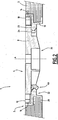
- the flange 22 serves as a support for the buffer 4 when it is placed on the frame 2 in the closed position, as shown in FIG. Figure 2 .
- the flange 22 comprises a radial and upwardly facing bearing face 23 and a guide face 24, inclined axially upwards and radially inwards.
- the bearing face 23 is provided to serve as a support for the buffer 4.
- the guide face 24 has a frustoconical shape converging downwards.
- the buffer 4 comprises on the lower surface of the web 8 a reinforcing rib 26.
- the rib 26 comprises an annular central rib 28 and radial ribs 30 extending radially in a star towards the peripheral edge 32 of the web 8 from the central rib 28.
- the central rib 28 is of polygonal shape and is more precisely heptagonal.
- Each of the radial ribs 30 extends from one of the vertices of the central rib 28.
- the rib 26 therefore comprises seven radial ribs 30.
- the buffer 4 comprises a latch 34 disposed at the free end of an arm 36 extending circumferentially in cantilever from the free radial end of a radial rib 30.
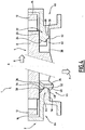
- the arm 36 is radially flexible so that the latch 34 is movable radially inwards relative to the buffer 4, against the return force exerted by the arm 36, as illustrated by the arrow C on the Figure 3 .
- the rib 26 further comprises a rib 30 dividing at a distance from the edge 32 into two branches 38 each terminating in a retaining hook 40 projecting radially outwardly from the free radial end of the leg 38. hooks 40 are rigid.
- the hooks 40 and the latch 34 are arranged in opposite peripheral zones of the buffer 4. In the example shown, these zones are diametrically opposed.
- the rib 26 On both sides of the hooks 40, the rib 26 comprises two ribs 30 each extended at its free end by a guide rib 42 extending circumferentially away from the rib 30 terminating in the hooks 40.
- the frame 2 comprises a stop 44 formed on the flange 22 and intended to cooperate with the latch 34.
- the stop 44 and the latch 34 together form a latch 45 for locking the buffer 4 in the closed position on the frame 2.
- the latch 34 comprises a lower sliding ramp 46 and an upper locking ramp 48.
- the lower ramp 46 is inclined radially outwards and axially downwards.
- the upper ramp 48 is inclined radially towards the outside and axially upwards.
- Stopper 44 includes an upper sliding surface 50 and a lower locking surface 52.
- the upper surface 50 is constituted by the bottom of a notch 54 formed in the collar 22.
- the lower surface 52 is formed on a protuberance 56 projecting downwardly from the collar 22 on a limited angular scent of it.
- the upper surface 50 is inclined radially inwards and axially upwards.
- the lower surface 52 is inclined radially inwardly and axially downwardly.
- Each hook 40 projects radially outwardly from the free end of the leg 38 of the rib 30.
- Each hook 40 comprises at its free end a bearing surface 58 inclined radially outwards and axially upwards.
- the flange 22 comprises facing each hook 40 a protuberance 60 projecting downwards and provided with a bearing surface 62 homologous to the bearing surface 58 of the hook 40.
- the bearing surface 62 of the collar 22 is inclined radially inwards and axially downwards.
- the buffer 4 is placed on the flange 22, the hooks 40 are engaged under the flange 22, and the latch 34 is engaged under the stop 44.
- the buffer 4 is retained on the frame 2 by a resilient interlocking device formed by the latch 45, disposed in a first region 64, and by a rigid attachment device formed by the hooks 40 engaging under the flange 22, disposed in a second region 66 opposite the first region 64.
- the latch 34 is resiliently biased by the arm 36 against the stop 44.
- the latch 34 is supported by its upper ramp 48 against the lower surface 52 of the stop 44, and pushes radially against the stop 44.
- the latch 45 in the locked position biases the buffer 4 axially downwardly against the flange 22 (arrow P).
- the buffer 4 is axially biased downwards, bearing against the flange 22.
- the buffer 4 is biased radially and axially in abutment against the frame 2 with a prestress, under the effect of the latch 34 in abutment against the stop 44, thereby preventing the sound of slamming the buffer on the frame when passing vehicles on the buffer.
- the operator uses the operating handle 10 which he grasps by hand or with the aid of an appropriate tool such as a pickaxe for example, and translate the stamp 4 on the frame to reach a tilting position of the buffer allowing the engagement of the hooks 40 under the flange 22 of the frame.
- the buffer 4 is then slightly raised in the first region 64, the latch 34 bearing by its lower ramp 46 against the upper surface 50 of the abutment 44 of the frame.
- the operator exerts on it, in a location substantially opposite the locking device, a force directed downwards, the inclinations of the lower ramp 46 of the latch 34 and the surface upper 50 of the stop 44 then allowing the displacement of the latch 34 radially inwardly with an elastic deformation of the arm 36, and the lowering of the buffer 4 in the closed position.
- the buffer 4 bears on the flange 22 and the latch 34 is engaged under the stop 44, the upper ramp 48 of the latch 34 being biased in elastic support against the lower surface 52 of the stop 44.
- the inclinations of the upper ramp 48 and the lower surface 52 are chosen so that the buffer 4 can be lifted by exerting a significant effort to allow the latch 34 to cross the stop 44 in the unlocking direction.
- a specific tool such as for example the failure of a pickaxe is inserted between the operating handle 12 and the wall of the housing 16 receiving the handle 12, and, bearing with the tool on the edge of the frame and by acting with the tool on the handle 12, the operator then exerts on the tool a lever effect so as to lift the buffer 4 in the first region 64 against the latch 45, thus causing the unlocking of the buffer. It is then sufficient for the operator, by grasping the handle 12 by hand or with the aid of a specific tool, to act on the buffer 4 to first clear the hooks 40 of the collar 22, then in a second time to deposit the buffer 4.
- the manipulation of the buffer 4 is simple.
- the buffer 4 can be released from the frame 2 easily, releasing the latch 45 and then slightly lifting the pad 4 and sliding on the floor.
- the two handles 10 and 12 are asymmetrical with respect to the axis A of the frame 2. They thus form keying means to ensure that the buffer 4 is oriented relative to the frame 2 so as to engage properly, on the one hand, the latch 34 and the abutment 44, and on the other hand, the hooks 40 and the bearing surfaces 62 of the flange 22.
- the guide ribs 42 cooperate by their circumferential outer surfaces 68 with the guiding face 24 of the collar 22 to guide the pad 4 by report to the framework 2.
- the pad 4 is supported by the area of the peripheral edge 32 of its web 8 adjacent the hooks 40 and can easily pivot about a radial direction passing through this area because it is rounded.
- the guide ribs 42 disposed on either side of the hooks 40 prevent this pivoting movement by bearing against the guide face 24, while allowing the tilting of the buffer 4 downwards in the closed position.
- the guide ribs 42 thus facilitate the placement of the buffer 4 on the frame 2, and prevent jamming during the closing operation of the buffer.
- the hooks 40 and the flange 22 form additional fastening members of a simple removable attachment device of the buffer 4 on the frame 2.
- the hooks 40 require little material and are easily obtained during the manufacture of the buffer 4.
- the buffer 4 and the frame 2 can be obtained easily and at low cost.
- the resilient locking device (latch 45) and the rigid attachment device (hooks 40 and flange 22) are arranged in diametrically opposite regions of the manhole.
- the hooking members of the hooking device must be arranged in the peripheral zone of the pad biased radially against the frame because of the radial resultant of the resilient locking device on the pad.
- the attachment members are therefore preferably located in the peripheral zone delimited by the diameter of the web 8 perpendicular to the radius passing through the latch 34 and opposite to the latch 34.
Landscapes
- Engineering & Computer Science (AREA)
- Environmental & Geological Engineering (AREA)
- Life Sciences & Earth Sciences (AREA)
- General Life Sciences & Earth Sciences (AREA)
- Mining & Mineral Resources (AREA)
- Paleontology (AREA)
- Civil Engineering (AREA)
- General Engineering & Computer Science (AREA)
- Structural Engineering (AREA)
- Underground Structures, Protecting, Testing And Restoring Foundations (AREA)
Applications Claiming Priority (2)
| Application Number | Priority Date | Filing Date | Title |
|---|---|---|---|
| FR0854939A FR2933994B1 (fr) | 2008-07-21 | 2008-07-21 | Dispositif de voirie muni d'un loquet de verrouillage |
| PCT/FR2009/051465 WO2010010294A1 (fr) | 2008-07-21 | 2009-07-21 | Dispositif de voirie muni d'un loquet de verrouillage |
Publications (2)
| Publication Number | Publication Date |
|---|---|
| EP2318596A1 EP2318596A1 (fr) | 2011-05-11 |
| EP2318596B1 true EP2318596B1 (fr) | 2016-05-11 |
Family
ID=40342599
Family Applications (1)
| Application Number | Title | Priority Date | Filing Date |
|---|---|---|---|
| EP09740353.9A Active EP2318596B1 (fr) | 2008-07-21 | 2009-07-21 | Dispositif de voirie muni d'un loquet de verrouillage |
Country Status (6)
| Country | Link |
|---|---|
| EP (1) | EP2318596B1 (pl) |
| ES (1) | ES2584279T3 (pl) |
| FR (1) | FR2933994B1 (pl) |
| PL (1) | PL2318596T3 (pl) |
| PT (1) | PT2318596T (pl) |
| WO (1) | WO2010010294A1 (pl) |
Families Citing this family (2)
| Publication number | Priority date | Publication date | Assignee | Title |
|---|---|---|---|---|
| DE102012110941A1 (de) * | 2012-11-14 | 2014-05-15 | ACO Severin Ahlmann GmbH & Co Kommanditgesellschaft | Verschluss zum Verriegeln einer Abdeckung |
| BE1020826A3 (nl) * | 2013-01-14 | 2014-05-06 | L & S Top Solutions | Gronddeksel. |
Family Cites Families (7)
| Publication number | Priority date | Publication date | Assignee | Title |
|---|---|---|---|---|
| JPS61211425A (ja) * | 1985-03-14 | 1986-09-19 | Doi Seisakusho:Kk | 地中構造物用蓋開閉装置 |
| CH678639A5 (pl) * | 1989-07-11 | 1991-10-15 | Von Roll Ag | |
| FR2681356B1 (fr) * | 1991-09-16 | 1997-04-04 | Pont A Mousson | Regard de chaussee a tampon verrouille. |
| FR2711688B1 (fr) * | 1993-10-26 | 1995-12-29 | Pont A Mousson | Regard de chaussée à verrouillage par rotation du tampon. |
| DE20010316U1 (de) * | 2000-06-08 | 2001-10-18 | Broermann, Rita, 59609 Anröchte | Rinnenelement |
| DE202005010323U1 (de) * | 2005-07-01 | 2005-09-15 | Heinrich Meier Eisengieserei G | Schachtabdeckung mit dämpfender Einlage |
| FR2897880B1 (fr) * | 2006-02-28 | 2009-11-06 | Saint Gobain Pam Sa | Dispositif de fermeture. |
-
2008
- 2008-07-21 FR FR0854939A patent/FR2933994B1/fr not_active Expired - Fee Related
-
2009
- 2009-07-21 PL PL09740353.9T patent/PL2318596T3/pl unknown
- 2009-07-21 EP EP09740353.9A patent/EP2318596B1/fr active Active
- 2009-07-21 WO PCT/FR2009/051465 patent/WO2010010294A1/fr not_active Ceased
- 2009-07-21 PT PT97403539T patent/PT2318596T/pt unknown
- 2009-07-21 ES ES09740353.9T patent/ES2584279T3/es active Active
Also Published As
| Publication number | Publication date |
|---|---|
| PL2318596T3 (pl) | 2016-11-30 |
| FR2933994B1 (fr) | 2012-11-16 |
| PT2318596T (pt) | 2016-08-18 |
| EP2318596A1 (fr) | 2011-05-11 |
| ES2584279T3 (es) | 2016-09-26 |
| WO2010010294A1 (fr) | 2010-01-28 |
| FR2933994A1 (fr) | 2010-01-22 |
Similar Documents
| Publication | Publication Date | Title |
|---|---|---|
| EP1826321B1 (fr) | Dispositif de fermeture | |
| EP0391825B1 (fr) | Regard de chaussée verrouillable en ouverture | |
| EP1818458B1 (fr) | Dispositif permettant d'obturer un cadre, comprenant un panneau monté articulé amovible sur le cadre | |
| EP0420777B1 (fr) | Regard de chaussée à charnière verrouillé | |
| CA1163487A (fr) | Moyens de blocage pour dispositif de verrouillage de tampon de regard de chaussee | |
| EP2543800B1 (fr) | Dispositif de verrouillage et de déverrouillage d'au moins un élément de recouvrement sur un cadre de support de cet élément | |
| WO2010010294A1 (fr) | Dispositif de voirie muni d'un loquet de verrouillage | |
| EP2478158B1 (fr) | Dispositif de voirie comportant une attache de fixation et procédé correspondant | |
| KR20130142672A (ko) | 맨홀 잠금장치 | |
| EP1175533B1 (fr) | Dispositif de voirie | |
| EP0796949B1 (fr) | Dispositif de voirie à charnière comprenant un couvercle du type grille ou tampon et un cadre support | |
| EP1091046B1 (fr) | Dispositif de fermeture de regard de visite ou d'inspection | |
| EP2025818B1 (fr) | Ensemble de recouvrement | |
| FR2899253A1 (fr) | Dispositif de securite pour l'acces a une chambre technique situee sous une chaussee ou analogue | |
| FR2919012A1 (fr) | Dispositif d'articulation d'un element de couronnement, tel qu'un couvercle, a un cadre notamment de regard de chaussee | |
| JP4527297B2 (ja) | 分割型マンホール用蓋カバー | |
| JP4763098B1 (ja) | 地下構造物用鉄蓋におけるテーパー嵌合解除装置 | |
| JPH0739961Y2 (ja) | 跳上げ回動式マンホール蓋装置 | |
| EP2510158B1 (fr) | Ensemble a cadre et tampon de fermeture du cadre notamment pour regard de chaussee | |
| BE1020845A5 (fr) | Regard de chaussee a cadre et tampon ameliores. | |
| FR2667889A1 (fr) | Tampon de regard de chaussee, regard comportant ce tampon et anneau de verrouillage pour un tel tampon. | |
| JP2513047Y2 (ja) | 地下施設蓋の開閉構造 | |
| JP2006161423A (ja) | マンホール蓋開け器 | |
| JP3741409B2 (ja) | 鉄蓋開閉装置 | |
| FR3148612A1 (fr) | Dispositif d’obturation d’un regard |
Legal Events
| Date | Code | Title | Description |
|---|---|---|---|
| PUAI | Public reference made under article 153(3) epc to a published international application that has entered the european phase |
Free format text: ORIGINAL CODE: 0009012 |
|
| 17P | Request for examination filed |
Effective date: 20110121 |
|
| AK | Designated contracting states |
Kind code of ref document: A1 Designated state(s): AT BE BG CH CY CZ DE DK EE ES FI FR GB GR HR HU IE IS IT LI LT LU LV MC MK MT NL NO PL PT RO SE SI SK SM TR |
|
| AX | Request for extension of the european patent |
Extension state: AL BA RS |
|
| DAX | Request for extension of the european patent (deleted) | ||
| 17Q | First examination report despatched |
Effective date: 20111004 |
|
| RAP1 | Party data changed (applicant data changed or rights of an application transferred) |
Owner name: SAINT-GOBAIN PAM |
|
| GRAP | Despatch of communication of intention to grant a patent |
Free format text: ORIGINAL CODE: EPIDOSNIGR1 |
|
| INTG | Intention to grant announced |
Effective date: 20151124 |
|
| GRAS | Grant fee paid |
Free format text: ORIGINAL CODE: EPIDOSNIGR3 |
|
| GRAA | (expected) grant |
Free format text: ORIGINAL CODE: 0009210 |
|
| AK | Designated contracting states |
Kind code of ref document: B1 Designated state(s): AT BE BG CH CY CZ DE DK EE ES FI FR GB GR HR HU IE IS IT LI LT LU LV MC MK MT NL NO PL PT RO SE SI SK SM TR |
|
| REG | Reference to a national code |
Ref country code: GB Ref legal event code: FG4D Free format text: NOT ENGLISH |
|
| REG | Reference to a national code |
Ref country code: CH Ref legal event code: EP |
|
| REG | Reference to a national code |
Ref country code: AT Ref legal event code: REF Ref document number: 798794 Country of ref document: AT Kind code of ref document: T Effective date: 20160515 |
|
| REG | Reference to a national code |
Ref country code: IE Ref legal event code: FG4D Free format text: LANGUAGE OF EP DOCUMENT: FRENCH |
|
| REG | Reference to a national code |
Ref country code: DE Ref legal event code: R096 Ref document number: 602009038604 Country of ref document: DE |
|
| REG | Reference to a national code |
Ref country code: FR Ref legal event code: PLFP Year of fee payment: 8 |
|
| REG | Reference to a national code |
Ref country code: CH Ref legal event code: NV Representative=s name: ARNOLD AND SIEDSMA AG, CH |
|
| REG | Reference to a national code |
Ref country code: PT Ref legal event code: SC4A Ref document number: 2318596 Country of ref document: PT Date of ref document: 20160818 Kind code of ref document: T Free format text: AVAILABILITY OF NATIONAL TRANSLATION Effective date: 20160809 |
|
| REG | Reference to a national code |
Ref country code: LT Ref legal event code: MG4D |
|
| REG | Reference to a national code |
Ref country code: NL Ref legal event code: MP Effective date: 20160511 |
|
| REG | Reference to a national code |
Ref country code: NO Ref legal event code: T2 Effective date: 20160511 Ref country code: ES Ref legal event code: FG2A Ref document number: 2584279 Country of ref document: ES Kind code of ref document: T3 Effective date: 20160926 |
|
| REG | Reference to a national code |
Ref country code: EE Ref legal event code: FG4A Ref document number: E012376 Country of ref document: EE Effective date: 20160809 |
|
| PG25 | Lapsed in a contracting state [announced via postgrant information from national office to epo] |
Ref country code: LT Free format text: LAPSE BECAUSE OF FAILURE TO SUBMIT A TRANSLATION OF THE DESCRIPTION OR TO PAY THE FEE WITHIN THE PRESCRIBED TIME-LIMIT Effective date: 20160511 Ref country code: NL Free format text: LAPSE BECAUSE OF FAILURE TO SUBMIT A TRANSLATION OF THE DESCRIPTION OR TO PAY THE FEE WITHIN THE PRESCRIBED TIME-LIMIT Effective date: 20160511 |
|
| PG25 | Lapsed in a contracting state [announced via postgrant information from national office to epo] |
Ref country code: SE Free format text: LAPSE BECAUSE OF FAILURE TO SUBMIT A TRANSLATION OF THE DESCRIPTION OR TO PAY THE FEE WITHIN THE PRESCRIBED TIME-LIMIT Effective date: 20160511 Ref country code: HR Free format text: LAPSE BECAUSE OF FAILURE TO SUBMIT A TRANSLATION OF THE DESCRIPTION OR TO PAY THE FEE WITHIN THE PRESCRIBED TIME-LIMIT Effective date: 20160511 Ref country code: GR Free format text: LAPSE BECAUSE OF FAILURE TO SUBMIT A TRANSLATION OF THE DESCRIPTION OR TO PAY THE FEE WITHIN THE PRESCRIBED TIME-LIMIT Effective date: 20160812 Ref country code: LV Free format text: LAPSE BECAUSE OF FAILURE TO SUBMIT A TRANSLATION OF THE DESCRIPTION OR TO PAY THE FEE WITHIN THE PRESCRIBED TIME-LIMIT Effective date: 20160511 |
|
| PG25 | Lapsed in a contracting state [announced via postgrant information from national office to epo] |
Ref country code: RO Free format text: LAPSE BECAUSE OF FAILURE TO SUBMIT A TRANSLATION OF THE DESCRIPTION OR TO PAY THE FEE WITHIN THE PRESCRIBED TIME-LIMIT Effective date: 20160511 Ref country code: SK Free format text: LAPSE BECAUSE OF FAILURE TO SUBMIT A TRANSLATION OF THE DESCRIPTION OR TO PAY THE FEE WITHIN THE PRESCRIBED TIME-LIMIT Effective date: 20160511 Ref country code: DK Free format text: LAPSE BECAUSE OF FAILURE TO SUBMIT A TRANSLATION OF THE DESCRIPTION OR TO PAY THE FEE WITHIN THE PRESCRIBED TIME-LIMIT Effective date: 20160511 |
|
| REG | Reference to a national code |
Ref country code: DE Ref legal event code: R097 Ref document number: 602009038604 Country of ref document: DE |
|
| PG25 | Lapsed in a contracting state [announced via postgrant information from national office to epo] |
Ref country code: SM Free format text: LAPSE BECAUSE OF FAILURE TO SUBMIT A TRANSLATION OF THE DESCRIPTION OR TO PAY THE FEE WITHIN THE PRESCRIBED TIME-LIMIT Effective date: 20160511 |
|
| PLBE | No opposition filed within time limit |
Free format text: ORIGINAL CODE: 0009261 |
|
| STAA | Information on the status of an ep patent application or granted ep patent |
Free format text: STATUS: NO OPPOSITION FILED WITHIN TIME LIMIT |
|
| PG25 | Lapsed in a contracting state [announced via postgrant information from national office to epo] |
Ref country code: MC Free format text: LAPSE BECAUSE OF FAILURE TO SUBMIT A TRANSLATION OF THE DESCRIPTION OR TO PAY THE FEE WITHIN THE PRESCRIBED TIME-LIMIT Effective date: 20160511 |
|
| 26N | No opposition filed |
Effective date: 20170214 |
|
| GBPC | Gb: european patent ceased through non-payment of renewal fee |
Effective date: 20160811 |
|
| REG | Reference to a national code |
Ref country code: IE Ref legal event code: MM4A |
|
| PG25 | Lapsed in a contracting state [announced via postgrant information from national office to epo] |
Ref country code: SI Free format text: LAPSE BECAUSE OF FAILURE TO SUBMIT A TRANSLATION OF THE DESCRIPTION OR TO PAY THE FEE WITHIN THE PRESCRIBED TIME-LIMIT Effective date: 20160511 |
|
| REG | Reference to a national code |
Ref country code: FR Ref legal event code: PLFP Year of fee payment: 9 |
|
| PG25 | Lapsed in a contracting state [announced via postgrant information from national office to epo] |
Ref country code: GB Free format text: LAPSE BECAUSE OF NON-PAYMENT OF DUE FEES Effective date: 20160811 Ref country code: IE Free format text: LAPSE BECAUSE OF NON-PAYMENT OF DUE FEES Effective date: 20160721 |
|
| PG25 | Lapsed in a contracting state [announced via postgrant information from national office to epo] |
Ref country code: LU Free format text: LAPSE BECAUSE OF NON-PAYMENT OF DUE FEES Effective date: 20160721 |
|
| PG25 | Lapsed in a contracting state [announced via postgrant information from national office to epo] |
Ref country code: HU Free format text: LAPSE BECAUSE OF FAILURE TO SUBMIT A TRANSLATION OF THE DESCRIPTION OR TO PAY THE FEE WITHIN THE PRESCRIBED TIME-LIMIT; INVALID AB INITIO Effective date: 20090721 Ref country code: CY Free format text: LAPSE BECAUSE OF FAILURE TO SUBMIT A TRANSLATION OF THE DESCRIPTION OR TO PAY THE FEE WITHIN THE PRESCRIBED TIME-LIMIT Effective date: 20160511 |
|
| REG | Reference to a national code |
Ref country code: FR Ref legal event code: PLFP Year of fee payment: 10 |
|
| PG25 | Lapsed in a contracting state [announced via postgrant information from national office to epo] |
Ref country code: MT Free format text: LAPSE BECAUSE OF FAILURE TO SUBMIT A TRANSLATION OF THE DESCRIPTION OR TO PAY THE FEE WITHIN THE PRESCRIBED TIME-LIMIT Effective date: 20160511 Ref country code: MK Free format text: LAPSE BECAUSE OF FAILURE TO SUBMIT A TRANSLATION OF THE DESCRIPTION OR TO PAY THE FEE WITHIN THE PRESCRIBED TIME-LIMIT Effective date: 20160511 Ref country code: IS Free format text: LAPSE BECAUSE OF FAILURE TO SUBMIT A TRANSLATION OF THE DESCRIPTION OR TO PAY THE FEE WITHIN THE PRESCRIBED TIME-LIMIT Effective date: 20160511 |
|
| PG25 | Lapsed in a contracting state [announced via postgrant information from national office to epo] |
Ref country code: BG Free format text: LAPSE BECAUSE OF FAILURE TO SUBMIT A TRANSLATION OF THE DESCRIPTION OR TO PAY THE FEE WITHIN THE PRESCRIBED TIME-LIMIT Effective date: 20160511 |
|
| PGFP | Annual fee paid to national office [announced via postgrant information from national office to epo] |
Ref country code: EE Payment date: 20180626 Year of fee payment: 10 |
|
| PGFP | Annual fee paid to national office [announced via postgrant information from national office to epo] |
Ref country code: BE Payment date: 20180614 Year of fee payment: 10 |
|
| PGFP | Annual fee paid to national office [announced via postgrant information from national office to epo] |
Ref country code: DE Payment date: 20180710 Year of fee payment: 10 Ref country code: NO Payment date: 20180710 Year of fee payment: 10 Ref country code: IT Payment date: 20180713 Year of fee payment: 10 |
|
| PGFP | Annual fee paid to national office [announced via postgrant information from national office to epo] |
Ref country code: ES Payment date: 20180903 Year of fee payment: 12 Ref country code: FI Payment date: 20180710 Year of fee payment: 10 |
|
| REG | Reference to a national code |
Ref country code: AT Ref legal event code: UEP Ref document number: 798794 Country of ref document: AT Kind code of ref document: T Effective date: 20160511 |
|
| REG | Reference to a national code |
Ref country code: DE Ref legal event code: R119 Ref document number: 602009038604 Country of ref document: DE |
|
| REG | Reference to a national code |
Ref country code: EE Ref legal event code: MM4A Ref document number: E012376 Country of ref document: EE Effective date: 20190731 |
|
| REG | Reference to a national code |
Ref country code: NO Ref legal event code: MMEP |
|
| REG | Reference to a national code |
Ref country code: FI Ref legal event code: MAE |
|
| REG | Reference to a national code |
Ref country code: CH Ref legal event code: PL |
|
| REG | Reference to a national code |
Ref country code: BE Ref legal event code: MM Effective date: 20190731 |
|
| PG25 | Lapsed in a contracting state [announced via postgrant information from national office to epo] |
Ref country code: NO Free format text: LAPSE BECAUSE OF NON-PAYMENT OF DUE FEES Effective date: 20190731 Ref country code: FI Free format text: LAPSE BECAUSE OF NON-PAYMENT OF DUE FEES Effective date: 20190721 Ref country code: EE Free format text: LAPSE BECAUSE OF NON-PAYMENT OF DUE FEES Effective date: 20190731 Ref country code: DE Free format text: LAPSE BECAUSE OF NON-PAYMENT OF DUE FEES Effective date: 20200201 |
|
| PG25 | Lapsed in a contracting state [announced via postgrant information from national office to epo] |
Ref country code: BE Free format text: LAPSE BECAUSE OF NON-PAYMENT OF DUE FEES Effective date: 20190731 Ref country code: LI Free format text: LAPSE BECAUSE OF NON-PAYMENT OF DUE FEES Effective date: 20190731 Ref country code: CH Free format text: LAPSE BECAUSE OF NON-PAYMENT OF DUE FEES Effective date: 20190731 |
|
| PG25 | Lapsed in a contracting state [announced via postgrant information from national office to epo] |
Ref country code: IT Free format text: LAPSE BECAUSE OF NON-PAYMENT OF DUE FEES Effective date: 20190721 |
|
| REG | Reference to a national code |
Ref country code: ES Ref legal event code: FD2A Effective date: 20201201 |
|
| PG25 | Lapsed in a contracting state [announced via postgrant information from national office to epo] |
Ref country code: ES Free format text: LAPSE BECAUSE OF NON-PAYMENT OF DUE FEES Effective date: 20190722 |
|
| PGFP | Annual fee paid to national office [announced via postgrant information from national office to epo] |
Ref country code: CZ Payment date: 20210629 Year of fee payment: 13 |
|
| PGFP | Annual fee paid to national office [announced via postgrant information from national office to epo] |
Ref country code: PL Payment date: 20210621 Year of fee payment: 13 |
|
| PGFP | Annual fee paid to national office [announced via postgrant information from national office to epo] |
Ref country code: AT Payment date: 20210625 Year of fee payment: 13 |
|
| PGFP | Annual fee paid to national office [announced via postgrant information from national office to epo] |
Ref country code: PT Payment date: 20210721 Year of fee payment: 13 |
|
| REG | Reference to a national code |
Ref country code: AT Ref legal event code: MM01 Ref document number: 798794 Country of ref document: AT Kind code of ref document: T Effective date: 20220721 |
|
| PG25 | Lapsed in a contracting state [announced via postgrant information from national office to epo] |
Ref country code: PT Free format text: LAPSE BECAUSE OF NON-PAYMENT OF DUE FEES Effective date: 20230123 Ref country code: CZ Free format text: LAPSE BECAUSE OF NON-PAYMENT OF DUE FEES Effective date: 20220721 Ref country code: AT Free format text: LAPSE BECAUSE OF NON-PAYMENT OF DUE FEES Effective date: 20220721 |
|
| PG25 | Lapsed in a contracting state [announced via postgrant information from national office to epo] |
Ref country code: PL Free format text: LAPSE BECAUSE OF NON-PAYMENT OF DUE FEES Effective date: 20220721 |
|
| PGFP | Annual fee paid to national office [announced via postgrant information from national office to epo] |
Ref country code: FR Payment date: 20240611 Year of fee payment: 16 |
|
| PGFP | Annual fee paid to national office [announced via postgrant information from national office to epo] |
Ref country code: TR Payment date: 20240705 Year of fee payment: 16 |
|
| PG25 | Lapsed in a contracting state [announced via postgrant information from national office to epo] |
Ref country code: FR Free format text: LAPSE BECAUSE OF NON-PAYMENT OF DUE FEES Effective date: 20250731 |