EP2318162B2 - Giessspiegelmessung in einer kokille durch ein faseroptisches messverfahren - Google Patents
Giessspiegelmessung in einer kokille durch ein faseroptisches messverfahren Download PDFInfo
- Publication number
- EP2318162B2 EP2318162B2 EP09777551.4A EP09777551A EP2318162B2 EP 2318162 B2 EP2318162 B2 EP 2318162B2 EP 09777551 A EP09777551 A EP 09777551A EP 2318162 B2 EP2318162 B2 EP 2318162B2
- Authority
- EP
- European Patent Office
- Prior art keywords
- mould
- probe
- casting
- optical waveguide
- copper plate
- Prior art date
- Legal status (The legal status is an assumption and is not a legal conclusion. Google has not performed a legal analysis and makes no representation as to the accuracy of the status listed.)
- Active
Links
Images
Classifications
-
- B—PERFORMING OPERATIONS; TRANSPORTING
- B22—CASTING; POWDER METALLURGY
- B22D—CASTING OF METALS; CASTING OF OTHER SUBSTANCES BY THE SAME PROCESSES OR DEVICES
- B22D2/00—Arrangement of indicating or measuring devices, e.g. for temperature or viscosity of the fused mass
-
- B—PERFORMING OPERATIONS; TRANSPORTING
- B22—CASTING; POWDER METALLURGY
- B22D—CASTING OF METALS; CASTING OF OTHER SUBSTANCES BY THE SAME PROCESSES OR DEVICES
- B22D2/00—Arrangement of indicating or measuring devices, e.g. for temperature or viscosity of the fused mass
- B22D2/003—Arrangement of indicating or measuring devices, e.g. for temperature or viscosity of the fused mass for the level of the molten metal
-
- B—PERFORMING OPERATIONS; TRANSPORTING
- B22—CASTING; POWDER METALLURGY
- B22D—CASTING OF METALS; CASTING OF OTHER SUBSTANCES BY THE SAME PROCESSES OR DEVICES
- B22D11/00—Continuous casting of metals, i.e. casting in indefinite lengths
- B22D11/16—Controlling or regulating processes or operations
- B22D11/18—Controlling or regulating processes or operations for pouring
- B22D11/181—Controlling or regulating processes or operations for pouring responsive to molten metal level or slag level
- B22D11/182—Controlling or regulating processes or operations for pouring responsive to molten metal level or slag level by measuring temperature
-
- B—PERFORMING OPERATIONS; TRANSPORTING
- B22—CASTING; POWDER METALLURGY
- B22D—CASTING OF METALS; CASTING OF OTHER SUBSTANCES BY THE SAME PROCESSES OR DEVICES
- B22D11/00—Continuous casting of metals, i.e. casting in indefinite lengths
- B22D11/16—Controlling or regulating processes or operations
- B22D11/20—Controlling or regulating processes or operations for removing cast stock
- B22D11/201—Controlling or regulating processes or operations for removing cast stock responsive to molten metal level or slag level
- B22D11/202—Controlling or regulating processes or operations for removing cast stock responsive to molten metal level or slag level by measuring temperature
-
- G—PHYSICS
- G01—MEASURING; TESTING
- G01F—MEASURING VOLUME, VOLUME FLOW, MASS FLOW OR LIQUID LEVEL; METERING BY VOLUME
- G01F23/00—Indicating or measuring liquid level or level of fluent solid material, e.g. indicating in terms of volume or indicating by means of an alarm
- G01F23/22—Indicating or measuring liquid level or level of fluent solid material, e.g. indicating in terms of volume or indicating by means of an alarm by measuring physical variables, other than linear dimensions, pressure or weight, dependent on the level to be measured, e.g. by difference of heat transfer of steam or water
- G01F23/24—Indicating or measuring liquid level or level of fluent solid material, e.g. indicating in terms of volume or indicating by means of an alarm by measuring physical variables, other than linear dimensions, pressure or weight, dependent on the level to be measured, e.g. by difference of heat transfer of steam or water by measuring variations of resistance of resistors due to contact with conductor fluid
- G01F23/246—Indicating or measuring liquid level or level of fluent solid material, e.g. indicating in terms of volume or indicating by means of an alarm by measuring physical variables, other than linear dimensions, pressure or weight, dependent on the level to be measured, e.g. by difference of heat transfer of steam or water by measuring variations of resistance of resistors due to contact with conductor fluid thermal devices
- G01F23/247—Indicating or measuring liquid level or level of fluent solid material, e.g. indicating in terms of volume or indicating by means of an alarm by measuring physical variables, other than linear dimensions, pressure or weight, dependent on the level to be measured, e.g. by difference of heat transfer of steam or water by measuring variations of resistance of resistors due to contact with conductor fluid thermal devices for discrete levels
- G01F23/248—Constructional details; Mounting of probes
-
- G—PHYSICS
- G01—MEASURING; TESTING
- G01F—MEASURING VOLUME, VOLUME FLOW, MASS FLOW OR LIQUID LEVEL; METERING BY VOLUME
- G01F23/00—Indicating or measuring liquid level or level of fluent solid material, e.g. indicating in terms of volume or indicating by means of an alarm
- G01F23/22—Indicating or measuring liquid level or level of fluent solid material, e.g. indicating in terms of volume or indicating by means of an alarm by measuring physical variables, other than linear dimensions, pressure or weight, dependent on the level to be measured, e.g. by difference of heat transfer of steam or water
- G01F23/28—Indicating or measuring liquid level or level of fluent solid material, e.g. indicating in terms of volume or indicating by means of an alarm by measuring physical variables, other than linear dimensions, pressure or weight, dependent on the level to be measured, e.g. by difference of heat transfer of steam or water by measuring the variations of parameters of electromagnetic or acoustic waves applied directly to the liquid or fluent solid material
- G01F23/284—Electromagnetic waves
- G01F23/292—Light, e.g. infrared or ultraviolet
Definitions
- the invention provides a system and a method for measuring the level of the glass in a mold by means of one or more measuring fibers and / or by means of fiber-optic temperature detection probes arranged in the mold copper plate at the level of the casting mirror.
- the temperatures determined by the probes for fiber-optic temperature sensing can be used to determine the exact height of the pouring mirror.
- a known and common method for determining the height of the casting mirror uses radioactive particles, which are introduced into the mold, wherein the emitted radiation is measured in the different heights of the mold, whereby the height of the casting mirror is closed. To improve the measurement, it is possible to introduce a higher density of such particles in the mold.
- thermocouples Furthermore, methods are known in which the casting level of the mold is determined by a temperature detection by means of thermocouples.
- thermocouples can not be arranged at very close intervals.
- a single thermocouple is required for each individual measuring point, so that a great deal of material is required and, above all, a great amount of cabling.
- the thermocouples are also in relation to the magnetic fields of a electromagnetic brake or prone to electromagnetic stirring coils. When regularly changing the mold, a cumbersome reconnection of the cables is also necessary, with confusion occur or connections can be forgotten.
- EP 1 769 864 describes a method for determining a bath level of a continuous casting mold, in which a camera is to be used, which is directed to the back of the copper plate of a mold and detects the color changes of Kokillenkupferplatte in the infrared range.
- a disadvantage of such an arrangement is that such a camera system requires a lot of space and also a monitoring of the casting level is generally made much more difficult by cooling water components behind the mold copper plate. If the method according to optical waveguides is used to direct the infrared radiation directly from points of the mold copper plate to the camera, one needs for each measuring point an optical waveguide, which must be led to the camera and correctly connected.
- the publication DE 26 55 640 discloses a device for determining the melt level in a continuous casting mold, wherein a detector element made of a heat-sensitive magnetic material is used. By the temperature change in the mold wall can then be finally closed on the G manadorold.
- the generous arrangement of this system makes a highly spatially resolved G manapter linear impossible.
- this method is susceptible to interference with respect to external magnetic fields, as already mentioned above. Even with several of these devices, it is not possible to obtain sufficient information about the shape of a G manaptharide.
- the JP 09 085406 discloses a method for determining the G slimadorproof way a continuous casting mold, in which for measuring the luminance on the broad sides and the narrow sides of the mold each have a plurality of slots arranged in optical waveguides are introduced. A subsequent regulation evaluates this distribution of the luminance, controls the casting speed and thus determines the height of the pouring mirror.
- the JP 04 351254 and the JP 06 294685 describe a device for measuring the G mantage basically in a continuous casting mold, in which over the entire height of the mold at least one optical waveguide is disposed on the hot side of the mold and is connected to control the G mantage basically with a Temperaturausticiansystem.
- the DE 28 54 515 uses the thermal radiation of the melt to determine the level of the casting mirror. Via infrared level sensors, the information about the temperature distribution is taken and forwarded to the signal processing as analog or digital electrical signals.
- the JP H08-276257 discloses a system for determining the temperature distribution in a mold comprising optical fibers set in heat resistant stainless steel tubes embedded in a plurality of rows in a groove of the copper plate.
- the invention enables a reliable and highly spatially resolved detection of the casting mirror in a mold. No radiation guidelines have to be taken into account, such as in the context of radioactive detection methods.
- the system also has a higher spatial resolution than would be possible with thermocouples. In addition, eliminates the cabling of such systems. There is no susceptibility to surrounding magnetic fields.
- the system is easy to integrate into an existing mold copper plate and is also reusable.
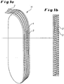
- FIG. 1a an embodiment of a probe 11 according to the invention is shown. Visible is a substantially cuboidal body of the probe 11, which is rounded arcuately at the top and at the bottom.
- the probe 11 four grooves 4 are provided in each of which an optical waveguide (optical fiber) or a fiber optic sensor 2 is arranged.
- measuring points 3 are shown, on which the temperature can be determined.
- the probe 11 may for example be installed in a groove in the side facing away from the melt of a mold copper plate, so that the optical waveguides 2 are oriented in the direction of the melt.
- the installation of the probe 11 takes place so that the optical waveguides 2 are in direct contact with the copper plate and are arranged between water cooling of the copper plate and the melt, in the direction of the melt.
- the illustrated probe 11 may also have other geometries as long as it is suitable to be installed in a groove of a mold copper plate.
- This probe, or groove probe 11 can also be integrated into existing systems in which it is mounted (also in addition to existing systems for temperature monitoring) in a groove in a copper plate.
- FIG. 1b shows an enlarged plan view of the area FIG. 1a in which the measuring points 3 of the optical waveguide 2 are located.
- the total vertical dimension of this area is 120 mm.
- the four adjacent optical waveguides 2 are arranged.
- the entire width of the area shown is about 5 mm, making the probe 11 is very compact.
- the distance between the individual parallel light guides 2 and thus the width spacing of the measuring points 3 is about 1 mm.
- the vertical distance of the measuring points 3 of an optical waveguide 2 is 4 mm in the exemplary embodiment.
- 1b shown advantageous displacement of the optical waveguide 2 are, however, in the vertical direction of the probe 11 measuring points 3 at intervals of 1 mm, since the four parallel optical waveguides 2 are arranged offset by 1 mm in length. This results in a length of 120 mm 120 measuring points 3.
- the distances of the optical waveguide 2, the size of the probe 11, the number of grooves 4 and optical fibers 2 and the distance of the measuring points 3, depending on the application can also be chosen differently, so that any densities of measuring points 3 can be realized. All mentioned dimensions are only for a better understanding of the embodiment.
- the diameter of the grooves 4 may generally be preferably between 0.5 mm and 10 mm or, depending on the application, also several centimeters in size.
- optical waveguide 2 are connected to a corresponding temperature evaluation system, wherein laser light is conducted into the optical waveguide 2 and with the aid of a suitable evaluation method, the temperature along the respective optical waveguide can be determined.
- the evaluation method for the fiber optic measuring method is the known fiber Bragg grating method (FBG method).
- FBG method fiber Bragg grating method
- optical waveguides 2 are used, the measuring points with a periodic variation of the refractive index, or grating with such variations, get impressed.
- Such measuring points 3 are in the FIGS. 1a and 1b located. This periodic variation of the refractive index leads to the fact that the optical waveguide 2 represents a dielectric mirror as a function of the periodicity for specific wavelengths at the measuring points 3.
- the Bragg wavelength is changed and exactly this is reflected.
- Light that does not satisfy the Bragg condition is not significantly affected by the Bragg grating.
- the different signals of the different measuring points 3 can then be distinguished from one another on the basis of transit time differences.
- the detailed structure of such fiber Bragg gratings, as well as the corresponding evaluation units are well known.
- the accuracy of the spatial resolution is given by the distance of the impressed measuring points.
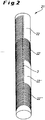
- FIG. 2 shows a further embodiment of a probe for temperature measurement according to the invention.
- the probe 21 shown has substantially the shape of an elongated cylinder or rod on which optical waveguides 2 are spirally wound. It is also possible to provide these optical fibers 2 in the same shape in grooves on the surface of the cylinder. In particular, in the FIG. 2 four optical fibers 2 wound on the cylinder. Each of these four optical waveguides is arranged in a region (22, 22 ', 22 ", 22"') which is only monitored by this one optical waveguide 2. The spiral arrangement of the optical waveguide allows a greater density of measuring points 3 perpendicular to the casting mirror. The connections of the optical waveguides 2 are not visible in the drawing.
- Such a probe 21 can then be arranged in a hole in a mold copper plate, which is perpendicular to the casting mirror.
- the bore can be selected to be slightly larger than the diameter of the probe 21, including the optical waveguides 2 FIG. 2
- Probe 21 shown provided with optical fibers 2 measuring range of 120 mm, which is divided into four areas (22, 22 ', 22 ", 22"') of 30 mm.
- the probe 21 shown is just wrapped so that the measuring points 3 are located on its side facing the melt. These measuring points 3 lie on a line and have a distance of 1 mm.
- the probe 21 can be installed for temperature monitoring at any height of the mold, but in particular at the level of the casting mirror, whereby a determination of the exact G fauxLiteledgesburg is enabled. The evaluation of the information collected by the probe 21 is carried out according to one of the methods of description of the FIGS. 1 a and 1 b.
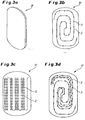
- FIG. 3a shows a further embodiment of a probe according to the invention.
- This probe 31 has substantially the shape of a plate, or is planar.
- Such a probe 31 can either be installed on the side facing away from the melt of the copper plate or in a slot in the copper plate on the probe are doing, as in the Figures 3b, 3c and 3d by way of example, optical waveguides 2 are arranged in corresponding grooves which are in contact with the mold copper plate in the direction of the melt.
- the arrangement of the optical waveguide 2 and the grooves can be spirally, as in FIG. 3b shown, done. In addition, several measuring points 3 of the light guide 2 are visible.
- Figure 3c shows a similar arrangement as FIG. 3b , but with a meandering arrangement of the optical waveguide 2, or the grooves.
- the probe 31 with the optical waveguides 2 is preferably arranged so that as many optical waveguides 2 are arranged perpendicular to the casting mirror, whereby an accurate height measurement is made possible.
- the sheet-like arrangement of the optical waveguide 2 on the plate-shaped probe 31 achieves a dissolution of the casting mirror height in the width direction, as a result of which it is better possible to obtain information about the shape of the casting mirror wave.
- 3d figure shows a further possibility of the arrangement of optical waveguides 2 on a plate-shaped probe 31, wherein two or more optical waveguides 2 are arranged spirally on the plate or in grooves.
- an optical fiber 2 is looped, so that its beginning and its end are in the same place.
- FIGS. 3a, 3b, 3c, 3d can also be provided a plurality of optical waveguide 2 a groove.
- these can be arranged offset lengthwise in order to further increase the number and density of the measuring points.
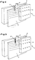
- FIG. 4 schematically shows the installation situation of a probe 11 after FIG. 1 ,
- the copper plates of the broad sides of the mold 8, the melt 7 and the pouring tube 6 are visible in the figure.
- the pouring tube 6 opens below the pouring mirror into the melt 7.
- a wave, or a standing wave forms at the level of the casting mirror.
- a probe 11 is after FIG. 1 installed.
- This probe 11 is installed in a groove in the mold copper plate and is preferably arranged so that it can measure the temperature of the copper plate 8 in the direction of the melt 7, without being influenced too much by a water cooling behind it. Therefore, the drawing is to be regarded as schematic.
- the visible areas 5 in the broad sides of the mold are holes of expansion screws or locations where, for example, thermocouples for temperature measurement can be arranged. However, these can not be used to determine the casting level.
- FIG. 5 schematically shows a mounting situation of a probe 21 after FIG. 2
- the arrangement of the mold itself corresponds FIG. 4
- the probe 21 used is arranged in a bore in a mold copper plate 8 on the broad side of the mold.
- the probe 21 covers an area above and below the casting mirror, as well as the probe 11 in FIG. 4 , Thus, only the copper of the copper plate 8 is located between the probe 21 and the casting mirror or the melt 7, so that an accurate temperature detection is possible.
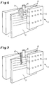
- FIG. 6 shows the arrangement of a probe 31 after FIG. 3 in a mold copper plate 8 a broadside of the mold.
- the probe 31 is installed in a slot perpendicular to the mold level of the respective mold copper plate 8, the fiber optic sensors 2 being mounted on the side of the probe 31 facing the melt.
- the plate with the sensors 2 could generally also be installed on the side facing away from the melt 7 of the mold copper plate 8 in a corresponding recess.
- the probe 31 covers a measuring range above and below the melt 7.
- a probe 31 thus arranged can also supply information perpendicular to the casting direction or in the width direction of the casting mirror. Thus, statements can be made about the shape and the change of an occurring G manaptwelle. This is also through the probes of FIGS. 1 . 2 and 7 possible, but then several of these probes are arranged perpendicular to the casting direction on G fauxLitewait.
- FIG. 7 shows a further inventive probe 41 in a broad side of a mold copper plate 8.
- the probe 41 consists of an optical waveguide 2, which is arranged in a bore perpendicular to the casting mirror in the region of the casting mirror.
- Such holes may have a diameter which is only slightly larger than the diameter of an optical waveguide, or an optical fiber or an optical waveguide including a possible sheath, z. B. stainless steel.
- the measuring range to be covered in all probes of the embodiments depending on the specific nature of the mold preferably extends between 100 mm and 200 mm, but can also be selected larger or smaller.
- All probes shown in the embodiments are reusable. This means that they can be removed in a simple manner with a change of mold copper plate, which is due periodically, and can be reintegrated including the optical waveguide in a new mold, which makes the probes according to the invention particularly cost-effective.
- the probes are preferably made of a thermally conductive material, for. B. stainless steel or copper.
- the optical fibers 2 have a stainless steel jacket for the purpose of improved protection against external influences.
- a plurality of such optical fibers 2 can generally be arranged within a stainless steel sheath or a stainless steel sheath, so that even in the case of seldom occurring defects of one fiber another fiber, which has already been laid in the sheath, can continue to be used.
- a plurality of fibers are arranged within a sheath for measurement, whereby the measurement further gains in accuracy, since the distance of the measuring points can be chosen as narrow as desired by moving the fibers.
- the optical fibers 2 may preferably have a diameter between 0.1 mm and 0.2 mm or other conventional diameter.
- the diameter of a shell, z. As stainless steel, is usually less than 5 mm.
- the optical fibers can also be connected via lens couplings, so-called “extended-beam connectors", with the evaluation device. Such couplings allow reliable signal transmission, are very robust and easy to handle.
Landscapes
- Physics & Mathematics (AREA)
- Thermal Sciences (AREA)
- Fluid Mechanics (AREA)
- General Physics & Mathematics (AREA)
- Engineering & Computer Science (AREA)
- Mechanical Engineering (AREA)
- Electromagnetism (AREA)
- Measuring Temperature Or Quantity Of Heat (AREA)
- Investigating Or Analysing Materials By Optical Means (AREA)
- Measurement Of Levels Of Liquids Or Fluent Solid Materials (AREA)
- Continuous Casting (AREA)
- Investigating Or Analyzing Materials Using Thermal Means (AREA)
Applications Claiming Priority (3)
| Application Number | Priority Date | Filing Date | Title |
|---|---|---|---|
| DE102008035608 | 2008-07-31 | ||
| DE102008060032A DE102008060032A1 (de) | 2008-07-31 | 2008-12-02 | Gießspiegelmessung in einer Kokille durch ein faseroptisches Messverfahren |
| PCT/EP2009/005529 WO2010012468A1 (de) | 2008-07-31 | 2009-07-30 | Giessspiegelmessung in einer kokille durch ein faseroptisches messverfahren |
Publications (3)
| Publication Number | Publication Date |
|---|---|
| EP2318162A1 EP2318162A1 (de) | 2011-05-11 |
| EP2318162B1 EP2318162B1 (de) | 2013-05-29 |
| EP2318162B2 true EP2318162B2 (de) | 2017-10-04 |
Family
ID=41461785
Family Applications (1)
| Application Number | Title | Priority Date | Filing Date |
|---|---|---|---|
| EP09777551.4A Active EP2318162B2 (de) | 2008-07-31 | 2009-07-30 | Giessspiegelmessung in einer kokille durch ein faseroptisches messverfahren |
Country Status (13)
| Country | Link |
|---|---|
| US (1) | US20110167905A1 (enExample) |
| EP (1) | EP2318162B2 (enExample) |
| JP (1) | JP5001461B2 (enExample) |
| KR (1) | KR20110023910A (enExample) |
| CN (1) | CN102112253B (enExample) |
| CA (1) | CA2732424A1 (enExample) |
| DE (1) | DE102008060032A1 (enExample) |
| MX (1) | MX2011001008A (enExample) |
| RU (1) | RU2466823C2 (enExample) |
| TW (1) | TW201006588A (enExample) |
| UA (1) | UA98880C2 (enExample) |
| WO (1) | WO2010012468A1 (enExample) |
| ZA (1) | ZA201100190B (enExample) |
Families Citing this family (26)
| Publication number | Priority date | Publication date | Assignee | Title |
|---|---|---|---|---|
| DE102010008480A1 (de) * | 2009-09-30 | 2011-03-31 | Sms Siemag Ag | Kokille zur Verarbeitung von flüssigem metallischem Material |
| DE102010034729A1 (de) * | 2010-02-09 | 2011-08-11 | SMS Siemag AG, 40237 | Metallurgisches Gefäß und Verfahren zur Herstellung einer Wandung des Gefäßes |
| DE102010035910A1 (de) * | 2010-06-09 | 2011-12-15 | Sms Siemag Ag | Einrichtung zur Temperaturmessung in einem Konverter |
| EP2422900A1 (en) | 2010-08-26 | 2012-02-29 | SMS Concast AG | Arrangement for measuring physical parameters in continuous casting moulds |
| US8509942B2 (en) * | 2011-03-31 | 2013-08-13 | Furukawa Electronic Co., Ltd. | Method for producing metal ingot, method for controlling liquid surface, and ultrafine copper alloy wire |
| DE102011085932A1 (de) | 2011-06-07 | 2012-12-13 | Sms Siemag Ag | Verfahren zum Regeln der Höhe des Gießspiegels in einer Kokille einer Stranggießanlage |
| DE102011088127A1 (de) * | 2011-06-07 | 2012-12-13 | Sms Siemag Ag | Strangführungssegment einer Strangführung einer Stranggießanlage und Verfahren zum Betreiben eines Strangführungssegments |
| US20160109277A1 (en) * | 2014-10-17 | 2016-04-21 | Elwin G. Hunt | Optically-based method and system for measuring liquids in tanks |
| JP6515329B2 (ja) * | 2015-04-08 | 2019-05-22 | 日本製鉄株式会社 | 連続鋳造用鋳型 |
| WO2017032392A1 (en) | 2015-08-21 | 2017-03-02 | Abb Schweiz Ag | A casting mold and a method for measuring temperature of a casting mold |
| AT517889B1 (de) * | 2015-10-28 | 2017-09-15 | Primetals Technologies Austria GmbH | Erfassung einer Gießspiegelhöhe in einer Kokille |
| CN107850495B (zh) * | 2016-04-19 | 2020-06-30 | 东京毅力科创株式会社 | 温度测量用基板以及温度测量系统 |
| EP3424614A1 (de) * | 2017-07-03 | 2019-01-09 | Primetals Technologies Austria GmbH | Einbau eines faseroptischen temperatursensors in eine kokille und kokille mit mehreren faseroptischen temperatursensoren |
| KR101892732B1 (ko) * | 2017-10-17 | 2018-08-28 | 한국원자력연구원 | 다접점 온도센서를 이용한 광대역 용융금속 액위 측정 장치 및 열 시스템 |
| TWI645922B (zh) * | 2018-01-30 | 2019-01-01 | 中國鋼鐵股份有限公司 | Method for reducing surface defects of cast embryo |
| IT201800006751A1 (it) * | 2018-06-28 | 2019-12-28 | Apparato e metodo di controllo della colata continua | |
| GB2576773A (en) | 2018-08-31 | 2020-03-04 | Advanced Fibreoptic Eng Ltd | Fluid level sensing device and method |
| CN109374089B (zh) * | 2018-12-04 | 2020-06-09 | 华中科技大学 | 液位和液体温度同时测量的光纤传感系统及其测量方法 |
| BE1026975B1 (fr) * | 2019-06-21 | 2020-08-12 | Ebds Eng Sprl | Lingotière de coulée continue de métaux, système de mesure de la température et système et procédé de détection de percée dans une installation de coulée continue de métaux |
| CN112935213B (zh) * | 2019-12-11 | 2022-10-28 | 中冶京诚工程技术有限公司 | 结晶器内钢水液面高度测量方法及相关装置 |
| CN111103029B (zh) * | 2019-12-26 | 2021-04-30 | 河南理工大学 | 一种用于煤仓煤位光纤光栅智能监测装置及监测方法 |
| CN114309520B (zh) * | 2020-09-30 | 2024-02-13 | 宝山钢铁股份有限公司 | 一种钢水液面稳定性监控的反馈方法 |
| CN113959527B (zh) * | 2021-10-21 | 2023-11-24 | 南昌大学 | 一种基于塑料光纤宏弯方法制备的液位传感器 |
| WO2023081151A1 (en) * | 2021-11-02 | 2023-05-11 | The Curators Of The University Of Missouri | Optical fiber interferometry sensor for high temperature mold gapmeasurement |
| EP4558294A1 (de) * | 2022-07-18 | 2025-05-28 | Primetals Technologies Austria GmbH | VIRTUELLER FÜLLSTANDSSENSOR FÜR EINE KOKILLE EINER STRANGGIEßANLAGE |
| KR102882047B1 (ko) | 2022-07-27 | 2025-11-05 | 세메스 주식회사 | 액적 분석 유닛 및 이를 포함하는 기판 처리 장치 |
Family Cites Families (26)
| Publication number | Priority date | Publication date | Assignee | Title |
|---|---|---|---|---|
| JPS5927270B2 (ja) | 1976-03-31 | 1984-07-04 | 三菱重工業株式会社 | 連続鋳造鋳型内の湯面検出装置 |
| JPS5496713U (enExample) * | 1977-12-20 | 1979-07-09 | ||
| JPS57154364A (en) * | 1981-03-20 | 1982-09-24 | Kobe Steel Ltd | Controlling method for surface temperature of ingot in continuous casting |
| FR2538545A1 (fr) * | 1982-12-27 | 1984-06-29 | Air Liquide | Dispositif de mesure du niveau d'un liquide dans un reservoir |
| JPS6027819A (ja) * | 1983-07-26 | 1985-02-12 | Yamatake Honeywell Co Ltd | レベル計 |
| JP2779031B2 (ja) * | 1990-01-12 | 1998-07-23 | 株式会社フジクラ | 光ファイバ温度センサ用面状ファイバ複合体 |
| JPH04351254A (ja) * | 1991-05-24 | 1992-12-07 | Sumitomo Metal Ind Ltd | 連続鋳造におけるモールドレベル測定装置 |
| RU2015827C1 (ru) * | 1991-07-11 | 1994-07-15 | Геннадий Александрович Ляхов | Способ контроля технологического процесса непрерывной разливки металла и устройство для его осуществления |
| JPH06277814A (ja) * | 1993-03-26 | 1994-10-04 | Sumitomo Heavy Ind Ltd | 連続鋳造機におけるブレークアウト検出装置 |
| JPH06294685A (ja) * | 1993-04-08 | 1994-10-21 | Sumitomo Metal Ind Ltd | 溶湯レベル検出装置 |
| RU2095902C1 (ru) * | 1995-07-28 | 1997-11-10 | Научный центр волоконной оптики при Институте общей физики РАН | Рамановский волоконный лазер (варианты) и брэгговская волоконнооптическая решетка |
| US5838700A (en) * | 1995-07-28 | 1998-11-17 | Nauchny Tsentr Volokonnoi Optiki Pri Institute Obschei Fiziki Rossiiskoi Akademii Nauk | Raman fibre laser, bragg fibre-optical grating and method for changing the refraction index in germanium silicate glass |
| JPH0985406A (ja) * | 1995-09-27 | 1997-03-31 | Sumitomo Metal Ind Ltd | 連続鋳造方法 |
| JPH09243470A (ja) * | 1996-03-13 | 1997-09-19 | Nkk Corp | 溶湯容器の溶湯レベル測定方法及び装置 |
| JPH1183601A (ja) * | 1997-09-05 | 1999-03-26 | Furukawa Electric Co Ltd:The | 液位計とそれを用いた地中浸潤面レベル計測装置 |
| GB9813095D0 (en) * | 1998-06-18 | 1998-08-19 | Secr Defence | Temperature sensing apparatus |
| JP2000111387A (ja) * | 1998-10-02 | 2000-04-18 | Toshiba Corp | 液位測定方法および装置 |
| JP2003302277A (ja) * | 2002-04-10 | 2003-10-24 | Sumitomo Electric Ind Ltd | 比重補正機能付き液位センサ |
| WO2004015349A2 (en) * | 2002-08-06 | 2004-02-19 | Lios Technology Gmbh | Furnace, method and monitoring system for monitoring its condition |
| EP1769864A1 (de) | 2005-09-29 | 2007-04-04 | Concast Ag | Verfahren und Vorrichtung zur Bestimmung der Höhe des Badspiegels in einer Stranggiesskokille |
| JP2007101508A (ja) * | 2005-10-07 | 2007-04-19 | Sumitomo Electric Ind Ltd | 温度測定方法及び温度測定装置 |
| JP4768405B2 (ja) * | 2005-11-09 | 2011-09-07 | 東日本旅客鉄道株式会社 | 光ファイバセンサー及び歪・温度観測システム |
| DE102006048086A1 (de) * | 2006-10-10 | 2008-04-17 | Sms Demag Ag | Vorrichtung für Resonanzoszillation und Verfahren zu deren Herstellung |
| CN101578506A (zh) * | 2007-01-10 | 2009-11-11 | 住友电气工业株式会社 | 对象物的温度分布测定方法及传感器单元 |
| JP4568301B2 (ja) * | 2007-04-12 | 2010-10-27 | 三島光産株式会社 | 連続鋳造用鋳型 |
| DE102008060507A1 (de) * | 2008-07-10 | 2010-01-14 | Sms Siemag Aktiengesellschaft | Temperaturmessung in einer Kokille durch ein faseroptisches Messverfahren |
-
2008
- 2008-12-02 DE DE102008060032A patent/DE102008060032A1/de not_active Withdrawn
-
2009
- 2009-07-30 JP JP2011520380A patent/JP5001461B2/ja not_active Expired - Fee Related
- 2009-07-30 UA UAA201102279A patent/UA98880C2/ru unknown
- 2009-07-30 CN CN200980131146.7A patent/CN102112253B/zh not_active Expired - Fee Related
- 2009-07-30 RU RU2011107233/02A patent/RU2466823C2/ru active
- 2009-07-30 US US13/056,887 patent/US20110167905A1/en not_active Abandoned
- 2009-07-30 EP EP09777551.4A patent/EP2318162B2/de active Active
- 2009-07-30 MX MX2011001008A patent/MX2011001008A/es not_active Application Discontinuation
- 2009-07-30 CA CA2732424A patent/CA2732424A1/en not_active Abandoned
- 2009-07-30 WO PCT/EP2009/005529 patent/WO2010012468A1/de not_active Ceased
- 2009-07-30 KR KR1020117002225A patent/KR20110023910A/ko not_active Ceased
- 2009-07-31 TW TW098125807A patent/TW201006588A/zh unknown
-
2011
- 2011-01-06 ZA ZA2011/00190A patent/ZA201100190B/en unknown
Also Published As
| Publication number | Publication date |
|---|---|
| ZA201100190B (en) | 2011-09-28 |
| EP2318162A1 (de) | 2011-05-11 |
| DE102008060032A1 (de) | 2010-02-04 |
| RU2466823C2 (ru) | 2012-11-20 |
| CN102112253A (zh) | 2011-06-29 |
| MX2011001008A (es) | 2011-03-25 |
| TW201006588A (en) | 2010-02-16 |
| KR20110023910A (ko) | 2011-03-08 |
| CN102112253B (zh) | 2014-08-27 |
| UA98880C2 (ru) | 2012-06-25 |
| RU2011107233A (ru) | 2012-09-10 |
| EP2318162B1 (de) | 2013-05-29 |
| WO2010012468A1 (de) | 2010-02-04 |
| CA2732424A1 (en) | 2010-02-04 |
| JP5001461B2 (ja) | 2012-08-15 |
| US20110167905A1 (en) | 2011-07-14 |
| JP2011529400A (ja) | 2011-12-08 |
Similar Documents
| Publication | Publication Date | Title |
|---|---|---|
| EP2318162B2 (de) | Giessspiegelmessung in einer kokille durch ein faseroptisches messverfahren | |
| EP2310155B1 (de) | Temperaturmessung in einer kokille durch ein faseroptisches messverfahren | |
| JP2011529400A5 (enExample) | ||
| EP3060364B1 (de) | Stranggiesskokille mit einem temperatursensor und herstellungsverfahren für die stranggiesskokille mit dem temperatursensor | |
| EP2312250B1 (de) | Metallurgisches Gefäß | |
| DE9318404U1 (de) | Einrichtung zum Bestimmen von Temperaturen an und in ausgedehnten Objekten | |
| EP2255164B1 (de) | Schiff mit einer vorrichtung zur tanküberwachung | |
| EP2483013B1 (de) | Kokille zur verarbeitung von flüssigem metallischem material | |
| WO2011023377A2 (de) | Überwachung von walzenlagern | |
| EP2539660B1 (de) | Giesspfanne oder zwischenbehälter zur aufnahme eines flüssigen metalls mit integriertem messelement zur erfassung der temperatur und/oder mechanischen belastung | |
| EP3074153B1 (de) | Verfahren zum erfassen des schmelze- und/oder schlackenniveaus in einem ofengefäss | |
| WO2019180161A1 (de) | Temperatursensor | |
| DE102009060548B4 (de) | Kokille für eine Stranggießanlage und Verwendung einer solchen Kokille | |
| EP1769864A1 (de) | Verfahren und Vorrichtung zur Bestimmung der Höhe des Badspiegels in einer Stranggiesskokille | |
| DE102010025562A1 (de) | Injektorkühlblock zur Halterung mindestens eines Injektors | |
| EP3654003A1 (de) | Mehrpunkt-temperaturmesssystem | |
| DE102009039101B4 (de) | Vorrichtung und Verfahren zur Messung von Kräften auf Walzen- oder Rollenoberflächen und/oder zur Messung von Temperaturen an Walzen- oder Rollenoberflächen | |
| EP3546906B1 (de) | Temperatursensoranordnung, temperatursensorbauteil für eine metallurgische anlage und verfahren zum herstellen eines solchen |
Legal Events
| Date | Code | Title | Description |
|---|---|---|---|
| PUAI | Public reference made under article 153(3) epc to a published international application that has entered the european phase |
Free format text: ORIGINAL CODE: 0009012 |
|
| 17P | Request for examination filed |
Effective date: 20110228 |
|
| AK | Designated contracting states |
Kind code of ref document: A1 Designated state(s): AT BE BG CH CY CZ DE DK EE ES FI FR GB GR HR HU IE IS IT LI LT LU LV MC MK MT NL NO PL PT RO SE SI SK SM TR |
|
| AX | Request for extension of the european patent |
Extension state: AL BA RS |
|
| DAX | Request for extension of the european patent (deleted) | ||
| 17Q | First examination report despatched |
Effective date: 20111124 |
|
| REG | Reference to a national code |
Ref country code: DE Ref legal event code: R079 Ref document number: 502009007238 Country of ref document: DE Free format text: PREVIOUS MAIN CLASS: B22D0002000000 Ipc: G01F0023240000 |
|
| GRAP | Despatch of communication of intention to grant a patent |
Free format text: ORIGINAL CODE: EPIDOSNIGR1 |
|
| RIC1 | Information provided on ipc code assigned before grant |
Ipc: B22D 11/18 20060101ALI20130108BHEP Ipc: G01F 23/292 20060101ALI20130108BHEP Ipc: G01F 23/24 20060101AFI20130108BHEP Ipc: B22D 2/00 20060101ALI20130108BHEP Ipc: B22D 11/20 20060101ALI20130108BHEP |
|
| GRAS | Grant fee paid |
Free format text: ORIGINAL CODE: EPIDOSNIGR3 |
|
| GRAA | (expected) grant |
Free format text: ORIGINAL CODE: 0009210 |
|
| AK | Designated contracting states |
Kind code of ref document: B1 Designated state(s): AT BE BG CH CY CZ DE DK EE ES FI FR GB GR HR HU IE IS IT LI LT LU LV MC MK MT NL NO PL PT RO SE SI SK SM TR |
|
| REG | Reference to a national code |
Ref country code: GB Ref legal event code: FG4D Free format text: NOT ENGLISH |
|
| REG | Reference to a national code |
Ref country code: CH Ref legal event code: EP |
|
| REG | Reference to a national code |
Ref country code: AT Ref legal event code: REF Ref document number: 614699 Country of ref document: AT Kind code of ref document: T Effective date: 20130615 |
|
| REG | Reference to a national code |
Ref country code: IE Ref legal event code: FG4D Free format text: LANGUAGE OF EP DOCUMENT: GERMAN |
|
| REG | Reference to a national code |
Ref country code: DE Ref legal event code: R096 Ref document number: 502009007238 Country of ref document: DE Effective date: 20130725 |
|
| REG | Reference to a national code |
Ref country code: LT Ref legal event code: MG4D |
|
| PG25 | Lapsed in a contracting state [announced via postgrant information from national office to epo] |
Ref country code: GR Free format text: LAPSE BECAUSE OF FAILURE TO SUBMIT A TRANSLATION OF THE DESCRIPTION OR TO PAY THE FEE WITHIN THE PRESCRIBED TIME-LIMIT Effective date: 20130830 Ref country code: NO Free format text: LAPSE BECAUSE OF FAILURE TO SUBMIT A TRANSLATION OF THE DESCRIPTION OR TO PAY THE FEE WITHIN THE PRESCRIBED TIME-LIMIT Effective date: 20130829 Ref country code: FI Free format text: LAPSE BECAUSE OF FAILURE TO SUBMIT A TRANSLATION OF THE DESCRIPTION OR TO PAY THE FEE WITHIN THE PRESCRIBED TIME-LIMIT Effective date: 20130529 Ref country code: PT Free format text: LAPSE BECAUSE OF FAILURE TO SUBMIT A TRANSLATION OF THE DESCRIPTION OR TO PAY THE FEE WITHIN THE PRESCRIBED TIME-LIMIT Effective date: 20130930 Ref country code: ES Free format text: LAPSE BECAUSE OF FAILURE TO SUBMIT A TRANSLATION OF THE DESCRIPTION OR TO PAY THE FEE WITHIN THE PRESCRIBED TIME-LIMIT Effective date: 20130909 Ref country code: SE Free format text: LAPSE BECAUSE OF FAILURE TO SUBMIT A TRANSLATION OF THE DESCRIPTION OR TO PAY THE FEE WITHIN THE PRESCRIBED TIME-LIMIT Effective date: 20130529 Ref country code: LT Free format text: LAPSE BECAUSE OF FAILURE TO SUBMIT A TRANSLATION OF THE DESCRIPTION OR TO PAY THE FEE WITHIN THE PRESCRIBED TIME-LIMIT Effective date: 20130529 Ref country code: IS Free format text: LAPSE BECAUSE OF FAILURE TO SUBMIT A TRANSLATION OF THE DESCRIPTION OR TO PAY THE FEE WITHIN THE PRESCRIBED TIME-LIMIT Effective date: 20130929 Ref country code: SI Free format text: LAPSE BECAUSE OF FAILURE TO SUBMIT A TRANSLATION OF THE DESCRIPTION OR TO PAY THE FEE WITHIN THE PRESCRIBED TIME-LIMIT Effective date: 20130529 |
|
| REG | Reference to a national code |
Ref country code: NL Ref legal event code: VDEP Effective date: 20130529 |
|
| PG25 | Lapsed in a contracting state [announced via postgrant information from national office to epo] |
Ref country code: HR Free format text: LAPSE BECAUSE OF FAILURE TO SUBMIT A TRANSLATION OF THE DESCRIPTION OR TO PAY THE FEE WITHIN THE PRESCRIBED TIME-LIMIT Effective date: 20130529 Ref country code: PL Free format text: LAPSE BECAUSE OF FAILURE TO SUBMIT A TRANSLATION OF THE DESCRIPTION OR TO PAY THE FEE WITHIN THE PRESCRIBED TIME-LIMIT Effective date: 20130529 Ref country code: BG Free format text: LAPSE BECAUSE OF FAILURE TO SUBMIT A TRANSLATION OF THE DESCRIPTION OR TO PAY THE FEE WITHIN THE PRESCRIBED TIME-LIMIT Effective date: 20130829 |
|
| PG25 | Lapsed in a contracting state [announced via postgrant information from national office to epo] |
Ref country code: LV Free format text: LAPSE BECAUSE OF FAILURE TO SUBMIT A TRANSLATION OF THE DESCRIPTION OR TO PAY THE FEE WITHIN THE PRESCRIBED TIME-LIMIT Effective date: 20130529 |
|
| BERE | Be: lapsed |
Owner name: SMS SIEMAG AG Effective date: 20130731 |
|
| PG25 | Lapsed in a contracting state [announced via postgrant information from national office to epo] |
Ref country code: CZ Free format text: LAPSE BECAUSE OF FAILURE TO SUBMIT A TRANSLATION OF THE DESCRIPTION OR TO PAY THE FEE WITHIN THE PRESCRIBED TIME-LIMIT Effective date: 20130529 Ref country code: EE Free format text: LAPSE BECAUSE OF FAILURE TO SUBMIT A TRANSLATION OF THE DESCRIPTION OR TO PAY THE FEE WITHIN THE PRESCRIBED TIME-LIMIT Effective date: 20130529 Ref country code: DK Free format text: LAPSE BECAUSE OF FAILURE TO SUBMIT A TRANSLATION OF THE DESCRIPTION OR TO PAY THE FEE WITHIN THE PRESCRIBED TIME-LIMIT Effective date: 20130529 Ref country code: SK Free format text: LAPSE BECAUSE OF FAILURE TO SUBMIT A TRANSLATION OF THE DESCRIPTION OR TO PAY THE FEE WITHIN THE PRESCRIBED TIME-LIMIT Effective date: 20130529 |
|
| PG25 | Lapsed in a contracting state [announced via postgrant information from national office to epo] |
Ref country code: RO Free format text: LAPSE BECAUSE OF FAILURE TO SUBMIT A TRANSLATION OF THE DESCRIPTION OR TO PAY THE FEE WITHIN THE PRESCRIBED TIME-LIMIT Effective date: 20130529 Ref country code: MC Free format text: LAPSE BECAUSE OF FAILURE TO SUBMIT A TRANSLATION OF THE DESCRIPTION OR TO PAY THE FEE WITHIN THE PRESCRIBED TIME-LIMIT Effective date: 20130529 Ref country code: NL Free format text: LAPSE BECAUSE OF FAILURE TO SUBMIT A TRANSLATION OF THE DESCRIPTION OR TO PAY THE FEE WITHIN THE PRESCRIBED TIME-LIMIT Effective date: 20130529 |
|
| REG | Reference to a national code |
Ref country code: CH Ref legal event code: PL |
|
| PLBI | Opposition filed |
Free format text: ORIGINAL CODE: 0009260 |
|
| PLAX | Notice of opposition and request to file observation + time limit sent |
Free format text: ORIGINAL CODE: EPIDOSNOBS2 |
|
| 26 | Opposition filed |
Opponent name: SAVEWAY GMBH & CO. KG Effective date: 20140228 Opponent name: SIEMENS VAI METALS TECHNOLOGIES GMBH Effective date: 20140228 |
|
| REG | Reference to a national code |
Ref country code: IE Ref legal event code: MM4A |
|
| REG | Reference to a national code |
Ref country code: FR Ref legal event code: ST Effective date: 20140331 |
|
| PG25 | Lapsed in a contracting state [announced via postgrant information from national office to epo] |
Ref country code: LI Free format text: LAPSE BECAUSE OF NON-PAYMENT OF DUE FEES Effective date: 20130731 Ref country code: CH Free format text: LAPSE BECAUSE OF NON-PAYMENT OF DUE FEES Effective date: 20130731 Ref country code: BE Free format text: LAPSE BECAUSE OF NON-PAYMENT OF DUE FEES Effective date: 20130731 |
|
| REG | Reference to a national code |
Ref country code: DE Ref legal event code: R026 Ref document number: 502009007238 Country of ref document: DE Effective date: 20140228 |
|
| PLBB | Reply of patent proprietor to notice(s) of opposition received |
Free format text: ORIGINAL CODE: EPIDOSNOBS3 |
|
| PG25 | Lapsed in a contracting state [announced via postgrant information from national office to epo] |
Ref country code: FR Free format text: LAPSE BECAUSE OF NON-PAYMENT OF DUE FEES Effective date: 20130731 |
|
| PG25 | Lapsed in a contracting state [announced via postgrant information from national office to epo] |
Ref country code: IE Free format text: LAPSE BECAUSE OF NON-PAYMENT OF DUE FEES Effective date: 20130730 |
|
| PG25 | Lapsed in a contracting state [announced via postgrant information from national office to epo] |
Ref country code: SM Free format text: LAPSE BECAUSE OF FAILURE TO SUBMIT A TRANSLATION OF THE DESCRIPTION OR TO PAY THE FEE WITHIN THE PRESCRIBED TIME-LIMIT Effective date: 20130529 |
|
| PG25 | Lapsed in a contracting state [announced via postgrant information from national office to epo] |
Ref country code: TR Free format text: LAPSE BECAUSE OF FAILURE TO SUBMIT A TRANSLATION OF THE DESCRIPTION OR TO PAY THE FEE WITHIN THE PRESCRIBED TIME-LIMIT Effective date: 20130529 Ref country code: CY Free format text: LAPSE BECAUSE OF FAILURE TO SUBMIT A TRANSLATION OF THE DESCRIPTION OR TO PAY THE FEE WITHIN THE PRESCRIBED TIME-LIMIT Effective date: 20130529 Ref country code: MT Free format text: LAPSE BECAUSE OF FAILURE TO SUBMIT A TRANSLATION OF THE DESCRIPTION OR TO PAY THE FEE WITHIN THE PRESCRIBED TIME-LIMIT Effective date: 20130529 |
|
| RAP2 | Party data changed (patent owner data changed or rights of a patent transferred) |
Owner name: SMS GROUP GMBH |
|
| PG25 | Lapsed in a contracting state [announced via postgrant information from national office to epo] |
Ref country code: LU Free format text: LAPSE BECAUSE OF NON-PAYMENT OF DUE FEES Effective date: 20130730 Ref country code: MK Free format text: LAPSE BECAUSE OF FAILURE TO SUBMIT A TRANSLATION OF THE DESCRIPTION OR TO PAY THE FEE WITHIN THE PRESCRIBED TIME-LIMIT Effective date: 20130529 Ref country code: HU Free format text: LAPSE BECAUSE OF FAILURE TO SUBMIT A TRANSLATION OF THE DESCRIPTION OR TO PAY THE FEE WITHIN THE PRESCRIBED TIME-LIMIT; INVALID AB INITIO Effective date: 20090730 |
|
| REG | Reference to a national code |
Ref country code: DE Ref legal event code: R082 Ref document number: 502009007238 Country of ref document: DE Representative=s name: HEMMERICH & KOLLEGEN, DE Ref country code: DE Ref legal event code: R081 Ref document number: 502009007238 Country of ref document: DE Owner name: SMS GROUP GMBH, DE Free format text: FORMER OWNER: SMS SIEMAG AG, 40237 DUESSELDORF, DE |
|
| PLAB | Opposition data, opponent's data or that of the opponent's representative modified |
Free format text: ORIGINAL CODE: 0009299OPPO |
|
| R26 | Opposition filed (corrected) |
Opponent name: PRIMETALS TECHNOLOGIES AUSTRIA GMBH Effective date: 20140228 |
|
| PLAY | Examination report in opposition despatched + time limit |
Free format text: ORIGINAL CODE: EPIDOSNORE2 |
|
| PLAH | Information related to despatch of examination report in opposition + time limit modified |
Free format text: ORIGINAL CODE: EPIDOSCORE2 |
|
| PLBC | Reply to examination report in opposition received |
Free format text: ORIGINAL CODE: EPIDOSNORE3 |
|
| PUAH | Patent maintained in amended form |
Free format text: ORIGINAL CODE: 0009272 |
|
| STAA | Information on the status of an ep patent application or granted ep patent |
Free format text: STATUS: PATENT MAINTAINED AS AMENDED |
|
| 27A | Patent maintained in amended form |
Effective date: 20171004 |
|
| AK | Designated contracting states |
Kind code of ref document: B2 Designated state(s): AT BE BG CH CY CZ DE DK EE ES FI FR GB GR HR HU IE IS IT LI LT LU LV MC MK MT NL NO PL PT RO SE SI SK SM TR |
|
| REG | Reference to a national code |
Ref country code: DE Ref legal event code: R102 Ref document number: 502009007238 Country of ref document: DE |
|
| PG25 | Lapsed in a contracting state [announced via postgrant information from national office to epo] |
Ref country code: LV Free format text: LAPSE BECAUSE OF FAILURE TO SUBMIT A TRANSLATION OF THE DESCRIPTION OR TO PAY THE FEE WITHIN THE PRESCRIBED TIME-LIMIT Effective date: 20130529 |
|
| PGFP | Annual fee paid to national office [announced via postgrant information from national office to epo] |
Ref country code: GB Payment date: 20200727 Year of fee payment: 12 |
|
| GBPC | Gb: european patent ceased through non-payment of renewal fee |
Effective date: 20210730 |
|
| PG25 | Lapsed in a contracting state [announced via postgrant information from national office to epo] |
Ref country code: GB Free format text: LAPSE BECAUSE OF NON-PAYMENT OF DUE FEES Effective date: 20210730 |
|
| P01 | Opt-out of the competence of the unified patent court (upc) registered |
Effective date: 20230707 |
|
| PGFP | Annual fee paid to national office [announced via postgrant information from national office to epo] |
Ref country code: DE Payment date: 20250722 Year of fee payment: 17 |
|
| PGFP | Annual fee paid to national office [announced via postgrant information from national office to epo] |
Ref country code: IT Payment date: 20250724 Year of fee payment: 17 |
|
| PGFP | Annual fee paid to national office [announced via postgrant information from national office to epo] |
Ref country code: AT Payment date: 20250722 Year of fee payment: 17 |