EP2317909B1 - Système médical avec lecteur de codes-barres compact pour consommables - Google Patents
Système médical avec lecteur de codes-barres compact pour consommables Download PDFInfo
- Publication number
- EP2317909B1 EP2317909B1 EP09781580.7A EP09781580A EP2317909B1 EP 2317909 B1 EP2317909 B1 EP 2317909B1 EP 09781580 A EP09781580 A EP 09781580A EP 2317909 B1 EP2317909 B1 EP 2317909B1
- Authority
- EP
- European Patent Office
- Prior art keywords
- light
- medical
- code
- optical
- optical code
- Prior art date
- Legal status (The legal status is an assumption and is not a legal conclusion. Google has not performed a legal analysis and makes no representation as to the accuracy of the status listed.)
- Active
Links
- 230000003287 optical effect Effects 0.000 claims description 184
- 239000013307 optical fiber Substances 0.000 claims description 136
- 238000005286 illumination Methods 0.000 claims description 110
- 238000012360 testing method Methods 0.000 claims description 97
- NOESYZHRGYRDHS-UHFFFAOYSA-N insulin Chemical compound N1C(=O)C(NC(=O)C(CCC(N)=O)NC(=O)C(CCC(O)=O)NC(=O)C(C(C)C)NC(=O)C(NC(=O)CN)C(C)CC)CSSCC(C(NC(CO)C(=O)NC(CC(C)C)C(=O)NC(CC=2C=CC(O)=CC=2)C(=O)NC(CCC(N)=O)C(=O)NC(CC(C)C)C(=O)NC(CCC(O)=O)C(=O)NC(CC(N)=O)C(=O)NC(CC=2C=CC(O)=CC=2)C(=O)NC(CSSCC(NC(=O)C(C(C)C)NC(=O)C(CC(C)C)NC(=O)C(CC=2C=CC(O)=CC=2)NC(=O)C(CC(C)C)NC(=O)C(C)NC(=O)C(CCC(O)=O)NC(=O)C(C(C)C)NC(=O)C(CC(C)C)NC(=O)C(CC=2NC=NC=2)NC(=O)C(CO)NC(=O)CNC2=O)C(=O)NCC(=O)NC(CCC(O)=O)C(=O)NC(CCCNC(N)=N)C(=O)NCC(=O)NC(CC=3C=CC=CC=3)C(=O)NC(CC=3C=CC=CC=3)C(=O)NC(CC=3C=CC(O)=CC=3)C(=O)NC(C(C)O)C(=O)N3C(CCC3)C(=O)NC(CCCCN)C(=O)NC(C)C(O)=O)C(=O)NC(CC(N)=O)C(O)=O)=O)NC(=O)C(C(C)CC)NC(=O)C(CO)NC(=O)C(C(C)O)NC(=O)C1CSSCC2NC(=O)C(CC(C)C)NC(=O)C(NC(=O)C(CCC(N)=O)NC(=O)C(CC(N)=O)NC(=O)C(NC(=O)C(N)CC=1C=CC=CC=1)C(C)C)CC1=CN=CN1 NOESYZHRGYRDHS-UHFFFAOYSA-N 0.000 claims description 48
- 230000005284 excitation Effects 0.000 claims description 44
- 239000012876 carrier material Substances 0.000 claims description 32
- 102000004877 Insulin Human genes 0.000 claims description 24
- 108090001061 Insulin Proteins 0.000 claims description 24
- 229940125396 insulin Drugs 0.000 claims description 24
- 239000003814 drug Substances 0.000 claims description 22
- 239000012491 analyte Substances 0.000 claims description 19
- 238000000034 method Methods 0.000 claims description 17
- 230000003595 spectral effect Effects 0.000 claims description 14
- GWEVSGVZZGPLCZ-UHFFFAOYSA-N Titan oxide Chemical compound O=[Ti]=O GWEVSGVZZGPLCZ-UHFFFAOYSA-N 0.000 claims description 8
- 210000001124 body fluid Anatomy 0.000 claims description 7
- 239000010839 body fluid Substances 0.000 claims description 7
- 230000035945 sensitivity Effects 0.000 claims description 7
- 238000004458 analytical method Methods 0.000 claims description 6
- 230000008569 process Effects 0.000 claims description 6
- 238000000149 argon plasma sintering Methods 0.000 claims description 5
- 229920000728 polyester Polymers 0.000 claims description 5
- 239000002207 metabolite Substances 0.000 claims description 4
- 229920003023 plastic Polymers 0.000 claims description 4
- OAICVXFJPJFONN-UHFFFAOYSA-N Phosphorus Chemical compound [P] OAICVXFJPJFONN-UHFFFAOYSA-N 0.000 claims description 2
- 230000006870 function Effects 0.000 description 31
- 238000001514 detection method Methods 0.000 description 23
- WQZGKKKJIJFFOK-GASJEMHNSA-N Glucose Natural products OC[C@H]1OC(O)[C@H](O)[C@@H](O)[C@@H]1O WQZGKKKJIJFFOK-GASJEMHNSA-N 0.000 description 21
- 239000008103 glucose Substances 0.000 description 21
- 238000005259 measurement Methods 0.000 description 19
- 239000008280 blood Substances 0.000 description 18
- 210000004369 blood Anatomy 0.000 description 18
- 239000000463 material Substances 0.000 description 15
- 238000003384 imaging method Methods 0.000 description 14
- 229940079593 drug Drugs 0.000 description 13
- 238000011156 evaluation Methods 0.000 description 13
- 238000013461 design Methods 0.000 description 11
- 125000006850 spacer group Chemical group 0.000 description 11
- 238000001802 infusion Methods 0.000 description 9
- 230000008878 coupling Effects 0.000 description 8
- 238000010168 coupling process Methods 0.000 description 8
- 238000005859 coupling reaction Methods 0.000 description 8
- 238000004020 luminiscence type Methods 0.000 description 8
- 239000011159 matrix material Substances 0.000 description 8
- 230000003993 interaction Effects 0.000 description 7
- 230000037452 priming Effects 0.000 description 7
- 230000001225 therapeutic effect Effects 0.000 description 7
- 238000005253 cladding Methods 0.000 description 6
- 239000000975 dye Substances 0.000 description 6
- 239000000835 fiber Substances 0.000 description 6
- 238000004806 packaging method and process Methods 0.000 description 6
- 239000004065 semiconductor Substances 0.000 description 6
- 230000008901 benefit Effects 0.000 description 5
- 230000008859 change Effects 0.000 description 5
- 238000006243 chemical reaction Methods 0.000 description 5
- 238000003780 insertion Methods 0.000 description 5
- 230000037431 insertion Effects 0.000 description 5
- 238000010521 absorption reaction Methods 0.000 description 4
- 239000011094 fiberboard Substances 0.000 description 4
- 238000004519 manufacturing process Methods 0.000 description 4
- 230000001603 reducing effect Effects 0.000 description 4
- 230000004044 response Effects 0.000 description 4
- 238000011161 development Methods 0.000 description 3
- 230000018109 developmental process Effects 0.000 description 3
- 238000005516 engineering process Methods 0.000 description 3
- 238000002594 fluoroscopy Methods 0.000 description 3
- 238000011010 flushing procedure Methods 0.000 description 3
- 230000006872 improvement Effects 0.000 description 3
- 238000009434 installation Methods 0.000 description 3
- 239000007788 liquid Substances 0.000 description 3
- 230000036961 partial effect Effects 0.000 description 3
- 238000012545 processing Methods 0.000 description 3
- 230000002829 reductive effect Effects 0.000 description 3
- 239000004408 titanium dioxide Substances 0.000 description 3
- 238000002679 ablation Methods 0.000 description 2
- 238000003491 array Methods 0.000 description 2
- 239000000969 carrier Substances 0.000 description 2
- HVYWMOMLDIMFJA-DPAQBDIFSA-N cholesterol Chemical compound C1C=C2C[C@@H](O)CC[C@]2(C)[C@@H]2[C@@H]1[C@@H]1CC[C@H]([C@H](C)CCCC(C)C)[C@@]1(C)CC2 HVYWMOMLDIMFJA-DPAQBDIFSA-N 0.000 description 2
- 239000011248 coating agent Substances 0.000 description 2
- 238000000576 coating method Methods 0.000 description 2
- 210000003722 extracellular fluid Anatomy 0.000 description 2
- 239000011521 glass Substances 0.000 description 2
- 238000012856 packing Methods 0.000 description 2
- 239000000049 pigment Substances 0.000 description 2
- 238000007639 printing Methods 0.000 description 2
- 230000009467 reduction Effects 0.000 description 2
- 230000003252 repetitive effect Effects 0.000 description 2
- 238000000926 separation method Methods 0.000 description 2
- 229910052710 silicon Inorganic materials 0.000 description 2
- 239000010703 silicon Substances 0.000 description 2
- 230000003068 static effect Effects 0.000 description 2
- 238000003860 storage Methods 0.000 description 2
- 239000000758 substrate Substances 0.000 description 2
- 230000001629 suppression Effects 0.000 description 2
- NMGSDTSOSIPXTN-UHFFFAOYSA-N C1CC=C=CC1 Chemical compound C1CC=C=CC1 NMGSDTSOSIPXTN-UHFFFAOYSA-N 0.000 description 1
- XDTMQSROBMDMFD-UHFFFAOYSA-N C1CCCCC1 Chemical compound C1CCCCC1 XDTMQSROBMDMFD-UHFFFAOYSA-N 0.000 description 1
- 241001631457 Cannula Species 0.000 description 1
- 238000000018 DNA microarray Methods 0.000 description 1
- 229910052693 Europium Inorganic materials 0.000 description 1
- 238000001467 acupuncture Methods 0.000 description 1
- WQZGKKKJIJFFOK-VFUOTHLCSA-N beta-D-glucose Chemical compound OC[C@H]1O[C@@H](O)[C@H](O)[C@@H](O)[C@@H]1O WQZGKKKJIJFFOK-VFUOTHLCSA-N 0.000 description 1
- 235000012000 cholesterol Nutrition 0.000 description 1
- 238000005345 coagulation Methods 0.000 description 1
- 230000015271 coagulation Effects 0.000 description 1
- 238000011109 contamination Methods 0.000 description 1
- 239000002537 cosmetic Substances 0.000 description 1
- 230000003247 decreasing effect Effects 0.000 description 1
- 230000001419 dependent effect Effects 0.000 description 1
- 238000009826 distribution Methods 0.000 description 1
- 230000000694 effects Effects 0.000 description 1
- 239000013013 elastic material Substances 0.000 description 1
- 238000000840 electrochemical analysis Methods 0.000 description 1
- 230000005670 electromagnetic radiation Effects 0.000 description 1
- OGPBJKLSAFTDLK-UHFFFAOYSA-N europium atom Chemical compound [Eu] OGPBJKLSAFTDLK-UHFFFAOYSA-N 0.000 description 1
- 239000012530 fluid Substances 0.000 description 1
- 230000036541 health Effects 0.000 description 1
- 238000002513 implantation Methods 0.000 description 1
- 238000002347 injection Methods 0.000 description 1
- 239000007924 injection Substances 0.000 description 1
- 230000000670 limiting effect Effects 0.000 description 1
- 238000000504 luminescence detection Methods 0.000 description 1
- 238000000691 measurement method Methods 0.000 description 1
- 238000002483 medication Methods 0.000 description 1
- 238000012634 optical imaging Methods 0.000 description 1
- 239000000123 paper Substances 0.000 description 1
- 239000002245 particle Substances 0.000 description 1
- 238000000206 photolithography Methods 0.000 description 1
- 239000004033 plastic Substances 0.000 description 1
- 229910052761 rare earth metal Inorganic materials 0.000 description 1
- 150000002910 rare earth metals Chemical class 0.000 description 1
- 230000002441 reversible effect Effects 0.000 description 1
- 210000003296 saliva Anatomy 0.000 description 1
- 238000006748 scratching Methods 0.000 description 1
- 230000002393 scratching effect Effects 0.000 description 1
- 239000007787 solid Substances 0.000 description 1
- 239000000243 solution Substances 0.000 description 1
- 238000001228 spectrum Methods 0.000 description 1
- 230000004936 stimulating effect Effects 0.000 description 1
- 230000002123 temporal effect Effects 0.000 description 1
- 210000001519 tissue Anatomy 0.000 description 1
- 239000012780 transparent material Substances 0.000 description 1
- 230000001960 triggered effect Effects 0.000 description 1
- 210000002700 urine Anatomy 0.000 description 1
- 230000000007 visual effect Effects 0.000 description 1
Images


Classifications
-
- A—HUMAN NECESSITIES
- A61—MEDICAL OR VETERINARY SCIENCE; HYGIENE
- A61B—DIAGNOSIS; SURGERY; IDENTIFICATION
- A61B5/00—Measuring for diagnostic purposes; Identification of persons
- A61B5/145—Measuring characteristics of blood in vivo, e.g. gas concentration, pH value; Measuring characteristics of body fluids or tissues, e.g. interstitial fluid, cerebral tissue
- A61B5/14546—Measuring characteristics of blood in vivo, e.g. gas concentration, pH value; Measuring characteristics of body fluids or tissues, e.g. interstitial fluid, cerebral tissue for measuring analytes not otherwise provided for, e.g. ions, cytochromes
-
- A—HUMAN NECESSITIES
- A61—MEDICAL OR VETERINARY SCIENCE; HYGIENE
- A61B—DIAGNOSIS; SURGERY; IDENTIFICATION
- A61B5/00—Measuring for diagnostic purposes; Identification of persons
-
- A—HUMAN NECESSITIES
- A61—MEDICAL OR VETERINARY SCIENCE; HYGIENE
- A61B—DIAGNOSIS; SURGERY; IDENTIFICATION
- A61B5/00—Measuring for diagnostic purposes; Identification of persons
- A61B5/14—Devices for taking samples of blood ; Measuring characteristics of blood in vivo, e.g. gas concentration within the blood, pH-value of blood
-
- A—HUMAN NECESSITIES
- A61—MEDICAL OR VETERINARY SCIENCE; HYGIENE
- A61B—DIAGNOSIS; SURGERY; IDENTIFICATION
- A61B5/00—Measuring for diagnostic purposes; Identification of persons
- A61B5/145—Measuring characteristics of blood in vivo, e.g. gas concentration, pH value; Measuring characteristics of body fluids or tissues, e.g. interstitial fluid, cerebral tissue
- A61B5/14532—Measuring characteristics of blood in vivo, e.g. gas concentration, pH value; Measuring characteristics of body fluids or tissues, e.g. interstitial fluid, cerebral tissue for measuring glucose, e.g. by tissue impedance measurement
-
- A—HUMAN NECESSITIES
- A61—MEDICAL OR VETERINARY SCIENCE; HYGIENE
- A61B—DIAGNOSIS; SURGERY; IDENTIFICATION
- A61B5/00—Measuring for diagnostic purposes; Identification of persons
- A61B5/145—Measuring characteristics of blood in vivo, e.g. gas concentration, pH value; Measuring characteristics of body fluids or tissues, e.g. interstitial fluid, cerebral tissue
- A61B5/1455—Measuring characteristics of blood in vivo, e.g. gas concentration, pH value; Measuring characteristics of body fluids or tissues, e.g. interstitial fluid, cerebral tissue using optical sensors, e.g. spectral photometrical oximeters
-
- A—HUMAN NECESSITIES
- A61—MEDICAL OR VETERINARY SCIENCE; HYGIENE
- A61B—DIAGNOSIS; SURGERY; IDENTIFICATION
- A61B5/00—Measuring for diagnostic purposes; Identification of persons
- A61B5/15—Devices for taking samples of blood
- A61B5/157—Devices characterised by integrated means for measuring characteristics of blood
-
- A—HUMAN NECESSITIES
- A61—MEDICAL OR VETERINARY SCIENCE; HYGIENE
- A61B—DIAGNOSIS; SURGERY; IDENTIFICATION
- A61B90/00—Instruments, implements or accessories specially adapted for surgery or diagnosis and not covered by any of the groups A61B1/00 - A61B50/00, e.g. for luxation treatment or for protecting wound edges
- A61B90/90—Identification means for patients or instruments, e.g. tags
- A61B90/94—Identification means for patients or instruments, e.g. tags coded with symbols, e.g. text
- A61B90/96—Identification means for patients or instruments, e.g. tags coded with symbols, e.g. text using barcodes
-
- A—HUMAN NECESSITIES
- A61—MEDICAL OR VETERINARY SCIENCE; HYGIENE
- A61B—DIAGNOSIS; SURGERY; IDENTIFICATION
- A61B90/00—Instruments, implements or accessories specially adapted for surgery or diagnosis and not covered by any of the groups A61B1/00 - A61B50/00, e.g. for luxation treatment or for protecting wound edges
- A61B90/90—Identification means for patients or instruments, e.g. tags
- A61B90/98—Identification means for patients or instruments, e.g. tags using electromagnetic means, e.g. transponders
-
- G—PHYSICS
- G01—MEASURING; TESTING
- G01N—INVESTIGATING OR ANALYSING MATERIALS BY DETERMINING THEIR CHEMICAL OR PHYSICAL PROPERTIES
- G01N33/00—Investigating or analysing materials by specific methods not covered by groups G01N1/00 - G01N31/00
- G01N33/48—Biological material, e.g. blood, urine; Haemocytometers
-
- A—HUMAN NECESSITIES
- A61—MEDICAL OR VETERINARY SCIENCE; HYGIENE
- A61B—DIAGNOSIS; SURGERY; IDENTIFICATION
- A61B2562/00—Details of sensors; Constructional details of sensor housings or probes; Accessories for sensors
- A61B2562/02—Details of sensors specially adapted for in-vivo measurements
- A61B2562/0295—Strip shaped analyte sensors for apparatus classified in A61B5/145 or A61B5/157
-
- A—HUMAN NECESSITIES
- A61—MEDICAL OR VETERINARY SCIENCE; HYGIENE
- A61B—DIAGNOSIS; SURGERY; IDENTIFICATION
- A61B2562/00—Details of sensors; Constructional details of sensor housings or probes; Accessories for sensors
- A61B2562/08—Sensors provided with means for identification, e.g. barcodes or memory chips
Definitions
- the invention relates to a medical system comprising at least one medical device for performing a medical function.
- the medical device is configured to interact with at least one medical consumable.
- Such medical systems are used, for example, in medical analysis, medical diagnostics or medical therapeutics.
- medical consumables plays an essential role.
- medical devices which, for example, have a diagnostic, analytical or therapeutic function and depend on one or more medical consumables to perform this function.
- medical analyzers which are used for the quantitative and / or qualitative detection of at least one analyte in a sample, for example for the detection of one or more metabolites in a body fluid.
- glucose measuring devices may be mentioned which are used to measure a glucose content, for example in blood, interstitial fluid, saliva or urine.
- test elements usually use one or more test elements, by means of which the quantitative and / or qualitative detection of the analyte takes place.
- these test elements may comprise one or more test fields which, upon contact with the analyte, have a specific chemically or physically detectable Perform a reaction or experience a specific, measurable change.
- the analysis devices can be set up to determine the analyte concentration optically, electrochemically or in another way with the test elements.
- the test elements may, for example, be test tubes, test strips, test tapes, test wheels with test fields arranged on a top and / or a circumference, foldable test papers with a plurality of test fields or in another form.
- the test elements may be present individually or for example in a plurality of magazine form, wherein in the latter case, a magazine with the test elements can be regarded as a consumable item.
- lancet systems in which, for example, a lancing device acts as a medical device.
- This lancing device is usually set up to perforate a skin area of a patient by means of one or more consumables in the form of lancets, for example to generate a sample of blood or interstitial fluid.
- Such medical systems are medication systems with metering devices.
- Such dosing devices usually work even with several types of medical consumables.
- cartridges or other storage containers of a medicament can be used, which is metered by means of the metering device.
- the drug itself and / or the drug with the corresponding vessel can be considered as a consumable.
- An example of such metering devices are medication pumps, such as insulin pumps.
- these dosing devices generally require further types of medical consumables, particularly catheters, for example.
- US 2004/0082918 A1 is a drug dosing system known. This includes a station with a barcode. A syringe with a needle can be received, the syringe also having a barcode. A slidably mounted scanner module is provided to read the bar codes. Among other things, the use of an optical fiber bundle for reading the barcodes will be described.
- test elements may differ from batch to batch, so that a batch-specific information may be required for the correct evaluation of the quantitative and / or qualitative detection of the at least one analyte in the sample.
- This can be, for example, information about how the optical luminescence or absorption properties, ie, for example, the luminescence or color of a test field of a Test element with which analyte concentration changes.
- electrochemical evaluation information can be included. In this case, for example, current characteristics and / or electrical potentials are measured.
- a lancing device may require information as to whether a correct type of consumable has been inserted into the lancing device, such as a lancet of a correct manufacturer or type , In general, such information may also be used, for example, for anti-counterfeiting of this type of consumables or other types of consumables, to distinguish articles of a correct or authorized manufacturer of "counterfeit" consumables. The latter can, in addition to avoiding economic damage, greatly reduce the risk of health damage from counterfeit medical devices.
- medical systems with metering devices such as insulin pumps, may require information about the nature and / or content of a cartridge of a drug. For example, if catheters or cannulas are used to dose the drug, then a fill volume of the catheter may be required to ensure proper initial priming or priming of the catheter.
- each batch of new test elements is accompanied by an information carrier, for example a so-called ROM key.
- the patient is required to insert this ROM key into the analyzer before using the new lot, so that correct information can be used to evaluate the measurement.
- this technique is generally associated with the risk that, especially in older patients or children, when using a new batch on the test strip replacement of the ROM key omitted. This may have consequences in terms of erroneous medication based on the erroneous measurement results, since possibly incorrect measurement results may be output in this case.
- optical codes there are therefore known medical systems in which two- or three-dimensional optical codes are applied to medical consumables, which can be read with a corresponding optical code reader of the medical device.
- Such systems are used for example in US 6,588,670 B2 described.
- US 4,476,149 or in US 6,168,957 Test strips are described which are equipped with corresponding barcodes as optical codes.
- Such optical codes can be referred to by way of example below.
- CIS contact imaging sensors
- US 2008/0088731 A1 a thin image sensor in which an image of the object is generated on an image sensor by means of a microlens array.
- US 2006/0202104 A1 describes a fingerprint sensor in which also takes place with a microlens array projection on a CCD / CMOS structure.
- a particular problem in this case is in particular the lighting, which is required for many code readers. Illumination through the medical consumable, such as in US 2006/0213994 A1 is not feasible in many cases due to the nature of many consumables, such as non-transparent test strips. Reflective illumination of the optical codes is also ruled out for many medical systems, since the available installation space does not allow the known systems and illumination techniques to sufficiently illuminate the area of the optical code.
- the medical system is intended to enable a reliable, space-saving and cost-effective exchange of information between at least one medical consumable and a medical device of the type described above.
- the medical system comprises at least one medical device for carrying out at least one medical function.
- this medical function may be any function required in the field of medicine or medical technology, in particular a diagnostic and / or analytical function and / or a therapeutic function.
- a diagnostic function can be understood to be a function which aims at the determination of at least one medical condition of a patient.
- An analytical function can be understood to be an almost arbitrary measurement function which aims at the measurement of one or more parameters, for example a sample.
- a qualitative and / or quantitative detection of at least one analyte in a liquid, solid or gaseous sample can be mentioned here.
- a therapeutic function can be understood as a function which is directed to a specific influencing of a body condition of a patient.
- the medical device may also perform several such medical functions, for example, combinations of diagnostic and therapeutic functions.
- the medical device can be designed to carry out this at least one medical function correspondingly by one or more mechanical devices and / or one or more electronic devices and / or one or more, possibly program-technically furnished, data processing devices.
- the medical device is set up to interact with at least one consumable to perform the at least one medical function.
- Collaboration means a functional interaction which does not necessarily require a physical connection between the medical device and the consumable.
- a physical connection may nevertheless be given, for example in the form of a mechanical and / or electrical connection.
- the medical device may comprise a holding device and / or a receptacle and / or a positioning device which receive or support the at least one medical consumable article.
- the medical consumable should be set up to enable or at least support the medical function of the medical device.
- the consumable may be arranged to cooperate with the medical device to ensure, for example, the analytical and / or diagnostic and / or therapeutic function.
- the term "consumables" is an article to understand, which can be preferably produced on an industrial scale. This consumable should be replaceable at will, whereas the medical device is usually suitable for multiple use. For example, the consumable may be intended for one-time use or for a limited number of uses only.
- the medical device further comprises at least one code reader for reading at least one piece of information of an optical code on the medical consumable.
- An optical code is to be understood as an information carrier which can be read by means of light in the visible and / or infrared and / or ultraviolet spectral range of the electromagnetic spectrum, in particular a two-dimensional and / or three-dimensional barcode.
- numerous other types of optical codes can also be realized, for example barcodes, grayscale codes or similar types of optical codes or combinations of the aforementioned and / or other types of codes.
- the optical code can, for example, be applied to a surface of the medical consumable, wherein a surface also analogously means that the optical code is covered by an at least partially optically transparent coating and thus is still optically or completely readable. In any case, the optical code should be readable from the outside by means of electromagnetic radiation of a suitable wavelength.
- the code reader of the medical device comprises at least one optical multi-channel evaluation unit, which is referred to below as an image sensor.
- the image sensor comprises a plurality of sensors. These sensors, which can be arranged, for example, one or two-dimensionally, for example in a one- or two-dimensional sensor array, should be suitable for receiving optical signals.
- the code reader further comprises at least one light-optical fiber plate.
- a light-optical fiber plate is to be understood as meaning an element which comprises a plurality of optical fibers, which are preferably all oriented parallel or substantially parallel. However, “substantially parallel” can also be understood as orientations which deviate from a parallelism, for example by not more than 20 °.
- an optical fiber is understood to mean a transparent element for light in the visible and / or infrared and / or ultraviolet spectral range, which acts as a light guide, in particular due to total internal reflection.
- the light-optical fiber plate may comprise such optical fibers, for example, as a bundle, wherein the optical fibers are, for example, fused, potted or glued together.
- these optical fibers are arranged in the light-optical fiber plate such that they are arranged in at least one dimension as the densest packing, so that the space is exploited by the light-optical fibers to a maximum degree.
- fibers with a round cross-section in a hexagonal arrangement be arranged.
- the light-optical fiber plate is designed as a flat plate, ie as a disk-shaped element of a predetermined thickness, which has a lateral extent, which is preferably greater than the thickness of this fiberboard.
- it may be a plate with a polygonal, round or other cross-section.
- the light-optical fiber plate is arranged to convey light from a first plane of the light-optical fiber plate to a second plane of the light-optical fiber plate without significantly changing the image.
- Each end of a light optical fiber acts at least approximately as a point light source, which substantially reproduces the light conditions at its opposite end.
- the code reader is constructed such that the light-optical fiber plate is arranged such that an image of the optical code is passed to the image sensor.
- the light-optical fiber plate is thus arranged between the image sensor and the optical code, so that the optical code is offset by the light-optical fiber plate as it were from the optical code adjacent the plane of the light-optical fiber plate on the opposite plane of this light-optical fiber plate, to be picked up by the image sensor to become.
- the image sensor and the light-optical fiber plate can form a unit, which can also be designed very compact.
- the image sensor and the light-optical fiber board can be connected to one another by a mechanical and / or positive and / or non-positive connection to the unit.
- the image sensor and the light-optical fiber plate, in particular the unit formed from these elements, may together have a thickness of less than 5 mm.
- the sensors of the image sensor can form a linear arrangement, that is to say a one-dimensional arrangement, or else a two-dimensional arrangement, for example a matrix arrangement.
- the image sensor may comprise one or more of the following sensors: a CCD sensor, in particular a CCD array; a CMOS sensor, in particular a CMOS array, a photodiode sensor, in particular a photodiode array; an organic photodetector, in particular an organic photodiode, in particular an array of such organic photodetectors.
- a CCD sensor in particular a CCD array
- CMOS sensor in particular a CMOS array
- a photodiode sensor in particular a photodiode array
- an organic photodetector in particular an organic photodiode, in particular an array of such organic photodetectors.
- the light-optical fiber plate is applied directly to the image sensor.
- the distance between the image sensor and the light-optical fiber plate is smaller than a distance between adjacent sensors of the image sensor. Since the light-optical fiber plate on its side facing the image sensor, the light conditions on its side facing away from the image sensor substantially identical, this arrangement is synonymous with an arrangement in which the image sensor rests substantially directly on the code. However, unlike the latter arrangement, as will be explained in more detail below, the light-optical fiberboard provides the opportunity to effect light coupling through the light-optical fiberboard so that the code can be efficiently illuminated.
- the light-optical fiber plate can basically be made of any transparent material.
- plastic materials and / or glasses can be used.
- These can also be configured in a core-cladding structure (core-cladding structure), wherein, for example, the sheaths of the individual optical fibers are fused or bonded together and form a common matrix of the light-optical fiber board, in which the actual fiber cores are embedded.
- core-cladding structure core-cladding structure
- the optical fibers and / or their cores, which are embedded in the optical fiber plate have a diameter of less than 100 ⁇ m, preferably 80 ⁇ m or less.
- the code reader also has at least one illumination device, ie a device which is designed to illuminate the optical code of the consumable.
- This illumination is unilateral, from the same side on which the image sensor is provided.
- the entire code reader can be designed to be very compact, with the medical consumable only having to be guided on one side to the code reader.
- This illumination from the detector side that is to say from the side of the image sensor, thus offers advantages with regard to the installation space.
- the illumination device accordingly comprises at least one light source, which can be arranged in different ways. Also, a plurality of light sources of different arrangement and / or different spectral properties may be provided.
- the light source as known from the prior art, can be used as a transmitted-light source and can be set up to illuminate the medical consumable in the region of the optical code.
- the consumable in this area should be at least partially transparent to the wavelength used or at least partially capable of transporting the light of the light source to the optical code.
- Various embodiments of such medical consumables or of carrier materials which meet these requirements are described below.
- a light source for one-sided illumination is possible and preferred in the context of the present invention.
- light of a wavelength in the visible and / or infrared and / or ultraviolet spectral range can be used for illumination.
- the spectral range is in the range between 300 nm and 3000 nm.
- suitable light sources can be used, in particular one or more light-emitting diodes based on inorganic and / or organic semiconductors, in particular also as light-emitting diode arrays.
- Other types of light sources can also be used, for example lasers, in particular semiconductor lasers.
- the illumination device can be designed as a monochromatic illumination device, but can also be set up to illuminate the medical consumable with light of different wavelengths.
- different wavelengths are to be understood spectral properties in which the spectral profile of the light at least does not coincide completely, for example in that the peak wavelengths are different from one another.
- the illumination device can be set up to illuminate the medical consumable, there in particular the optical code, simultaneously or else sequentially, ie at different points in time, with light of different wavelengths.
- a simultaneous illumination with light of different wavelengths is in principle possible, for example, accompanied by a corresponding spectral separation by the image sensor and / or another wavelength-selective element, for example one or more filters and / or one or more dichroic mirrors.
- the code reader may also be configured to perform a query-response scheme.
- the code reader can be set up to record the image of the optical code with a time delay for illumination by the illumination device.
- a circuit may be provided in which a signal recording by the image sensor only begins when the illumination is switched off by the light source.
- a pulsed scheme may be used, with an excitation pulse of, for example, less than 100 ⁇ sec. A start of measurement can then be offset by a time offset, for example of 200 .mu.sec, after the end of the excitation pulse.
- Such a query-response pulse scheme can be used in particular in the case of luminescent codes, for example codes which comprise one or more modules with fluorescent and / or phosphorescent media, for example from the group of rare-earth complexes such as europium.
- illumination by the illumination device is one-sided, i. the illumination takes place from the same side of the medical consumable as the observation by the light-optical fiber plate and the image sensor.
- the illumination can take place through the light-optical fiber plate.
- this can be realized by the light-optical fiber plate from the side, so for example at 90 ° to the orientation of the optical fibers in the light-optical fiber plate or at an angle which preferably deviates by not more than 20-30 ° from a right angle, is illuminated by at least one light source of the illumination device.
- the illumination can also take place essentially parallel to the optical fibers of the light-optical fiber plate. This can be done, for example, by illuminating the side of the image sensor through the light-optical fiber plate. Alternatively or additionally, however, can also be illuminated through the image sensor, so that the excitation light first penetrates the image sensor and then the light-optical fiber plate. This can be done, for example, when the image sensor is at least partially transparent to the excitation light used of the light source of the illumination device. For this purpose, for example, corresponding apertures may be provided in the image sensor through which the excitation light can pass, in order then to pass through the light-optical fiber plate to the medical consumable and the code.
- the material of the image sensor itself may also be at least partially transparent to the excitation light.
- the image sensor may be a semiconductor material (eg silicon) having a band gap, wherein the light source is arranged to emit light having a lower energy than the band gap.
- the image sensor is set up in such a way that it substantially or only insubstantially absorbs the excitation light of the light source, for example not more than 20%. In the case of silicon, this can be done, for example, by using light with a wavelength of more than 1000 nm.
- the optical code can comprise corresponding light converters which generate shorter-wave photons from the longer-wavelength photons of the excitation light of the light source, for example in the context of multiphoton processes.
- the illumination device can also be set up in order to illuminate the optical code from the side, ie preferably substantially perpendicular to a viewing direction of the light-optical fiber plate. This can be done, for example, by a carrier material of the medical consumable article in the region of the optical code, for example, again by a carrier material conducting the excitation light of the light source of the illumination device or transparent to this excitation light.
- the medical consumable at least in the region of the optical code, from the rear side, that is to say from the side facing away from the light-optical fiber plate and the image sensor.
- an at least partially transparent or light-conducting carrier material is preferred in this area of the medical consumable article.
- This type of illumination which can be used in addition to the other types of illumination, can be used predominantly for absorptive detection of the optical code, but also, for example, for luminescence detection.
- the image sensor can furthermore have at least two regions with different spectral sensitivity.
- the image sensor may comprise different sensors which have different spectral sensitivity.
- a plurality of wavelengths of light which are reflected by the optical code or emitted or emanating in any other way, can be used for detection.
- these different sensitivities may be achieved by intrinsically different sensitivities of the sensors, or one or more Filters are used to generate these different spectral sensitivities.
- the code reader can have at least one optical filter, in particular an edge filter and / or an interference filter.
- the optical code of the medical consumable article can in particular be composed of a plurality of optically readable modules as the smallest information unit.
- This smallest information unit can correspond, for example, to a "bit".
- the code is constructed two-dimensionally so that a module in two dimensions represents the smallest unit to be resolved by the code reader.
- the modules can be designed, for example, round or rectangular, in particular square, wherein the smallest edge length of a square corresponds to the dimension of a module. For example, modules with a width of 300 ⁇ m can be used.
- the light-optical fiber plate is designed in such a way and positioned relative to the optical code that this provides a sufficient resolution for reading the optical code. This is ensured by the medical device and / or the code reader and the medical consumables being positioned relative to one another such that a distance between the light-optical fiber plate and the optical code is smaller than a distance between the centers of adjacent modules of the code.
- the mean free path length, which photons have to cover from the modules of the code to the light-optical fiber plate should be smaller than the distance between the centers of adjacent modules, ie the dimensions of the optical code to be resolved.
- the medical system may include a positioning device.
- This positioning device can be set up to position the consumable and the medical device relative to each other, for example, to allow optimal reading of the optical code.
- the positioning device may be configured to position the medical device and the consumable relative to each other such that, in a reading position, the above-described condition regarding the distance between the light-optical fiber plate and the optical code and the distance between the centers of adjacent modules of the code is given.
- the positioning device may also be arranged to always ensure a constant distance between the consumable and the light-optical fiber plate, including, for example, an optional tolerance range for mispositioning.
- the positioning device may be arranged to always ensure a certain minimum distance between the light-optical fiber plate and the consumable. This can be advantageous in particular in the case of test elements, such as test strips, for example, which can be inserted in particular into the medical device. If the insertion takes place with too small a distance between the test element and the light-optical fiber board, this can for example result in damage (for example wear and / or scratching) of the light-optical fiber board and / or contamination thereof, for example due to adhesion to the test element Blood, lead. By a suitable embodiment of the positioning device, this can be prevented.
- the positioning device may comprise at least one spacer, which always ensures a minimum distance between the medical consumable, for example the test element, and the code reader, for example the light-optical fiber plate of the code reader.
- This spacer may comprise, for example, at least one rail (in particular a spacer rail), at least one attachment, at least one guide, at least one spacer plate and / or at least one spacer ring or combinations of said elements and / or further elements.
- the positioning device may comprise at least one pressure element which acts on the medical consumable with a force acting in the direction of the code reader.
- the pressure element may be configured to press the consumable against the spacer described above.
- a reverse application of force is possible, so a force applied, in which the Pressure element causes the code reader is pressed completely or partially against the medical consumables.
- the light-optical fiber plate and / or a unit comprising the light-optical fiber plate and the image sensor can be pressed against the consumable by the pressure element.
- the pressure element may comprise, for example, one or more spring elements, one or more elements of elastic materials or similar elements, which are usually used for a force application.
- the positioning device may for example be part of the medical device.
- the positioning device may be adapted to the type of medical device and / or the type of medical consumable and may include various types of mechanical devices.
- the positioning device may comprise holding devices for holding the medical consumable and / or in the medical device in such a way that the medical consumable is positioned in the reading position while maintaining the condition described above.
- the positioning device may accordingly comprise at least one rail for introducing the medical consumable, for example a test element.
- the positioning may also be a lateral positioning, that is, for example, a positioning in a plane perpendicular to the connection between the image sensor and consumables.
- the positioning device may also include a bearing surface on which or on which the medical consumable article can be placed or applied, so that the consumable is positioned in the reading position.
- the code reader may be arranged such that the optical code is completely imaged in an active sensor surface of the image sensor. This can take place, in particular if the light-optical fiber plate has no enlarging or reducing effect, for example, in that the active sensor surface of the image sensor is at least as large as the surface of the optical code. Alternatively or additionally, however, the light-optical fiber plate can also have an enlarging or reducing effect, so that the image of the optical code which generates the optical fiber plate on the side facing the image sensor is larger or smaller than the actual optical code.
- the image sensor with its active area may be smaller than the optical code, or it may be a magnifying or decreasing effect done by the light-optical fiber plate, which causes this.
- the image sensor takes only a portion of the optical code.
- the optical code may comprise repetitive, at least partially redundant information.
- the optical code may comprise repeating bit patterns or patterns of modules, wherein these repeating bit patterns or patterns of modules may be arranged such that at least one of these bit patterns or module patterns is completely imaged onto the active sensor surface of the image sensor.
- the code and / or the optically readable modules of the code may in particular be applied to the medical consumable by one or more of the following methods: a printing process on a surface of the medical consumable; a laser-induced dye conversion process; a mechanical deformation of a surface of the medical consumable or the medical consumable itself.
- a printing process on a surface of the medical consumable a laser-induced dye conversion process
- a mechanical deformation of a surface of the medical consumable or the medical consumable itself are generally applicable, such as mechanical ablation, ablation also by laser processing, implantation, photolithography or similar methods.
- the medical consumable may comprise in the region of the optical code a carrier material which has transparent and / or light-scattering properties. This means that the carrier material should be at least partially transparent or light-scattering, in particular for light of at least one light source of the illumination device.
- the optical code itself for example the modules of the optical code, can also be completely or partially arranged to interact differently with light of different wavelengths.
- materials for the optical code or the modules which, for example, have different excitation wavelengths, different absorption properties, different scattering properties or otherwise different optical properties for excitation light of the illumination device.
- the optical code can interact with light in various ways.
- the optical code may have at least partially luminescent properties, that is, for example, phosphorescent and / or fluorescent properties.
- the optical code in particular the modules of the optical code, preferably corresponding dyes, pigments, phosphors or the like.
- the optical code in particular the modules of the optical code, comprise at least one light converter which is set up to convert an excitation light, for example an excitation light of the illumination device and / or ambient light, into a light having a wavelength different from the excitation light.
- the light converter may comprise, for example, an up-converter or a down-converter, that is, a converter which can convert light into higher-energy light or lower-energy light.
- this light converter may again be in the form of a dye, a pigment, a phosphor or in a similar form.
- an excitation of the light converter by means of a corresponding excitation light, which can be detected by the code reader and / or the image sensor to read the information of the code.
- the medical consumable article in this area can comprise a carrier material which has diffusely photoconductive and / or transparent properties, in particular for excitation light, for example excitation light of the illumination device.
- the carrier material may comprise a polyester, for example Melinex.
- the carrier material, in particular the polyester can furthermore also be doped, for example with titanium dioxide.
- a substantially white overall impression of the carrier material may arise, wherein the carrier material nevertheless has diffuse light-scattering properties. In this way, for example, a uniform illumination of the code can be ensured.
- the medical consumable in the area of the optical code can also comprise a carrier with a carrier material, wherein the carrier can furthermore comprise at least one light converter in this area.
- This light converter which in turn may be an up-converter and / or a down-converter as described above, may in particular be designed to convert excitation light into light of different wavelengths.
- the light converter can be distributed uniformly in the carrier material so that light with the wavelength different from the excitation light illuminates the optical code substantially uniformly.
- substantially uniformly is meant an isotropic illumination in which the illumination of the code differs from a uniform illumination by less than 20%.
- the medical device may comprise an analyzer for detecting at least one analyte in a sample, for example a liquid sample, in particular a body fluid.
- a sample for example a liquid sample, in particular a body fluid.
- metabolites in the body fluid are suitable as the analyte, for example glucose, cholesterol and / or similar metabolites.
- a coagulation detection is possible.
- the analysis device can then be set up to cooperate with a medical consumable in the form of at least one test element, in particular a test strip and / or a test strip.
- a single test strip can be understood as a medical consumable, or, as stated above, also a plurality of test strips and / or test tapes, which can be accommodated for example in a corresponding magazine or a housing.
- the magazine and / or the housing can be provided with the optical code accordingly.
- the medical system may also comprise a metering device for metering at least one medicament, in particular a medication pump, for example an insulin pump.
- the consumable may comprise, for example, a catheter or a cannula (both terms are used synonymously in the following description) with which the dosing device cooperates.
- the medical system can accordingly be designed, for example, as a so-called "infusion set". Since catheters are usually delivered filled with air, flushing with a medical fluid, such as an insulin infusion, must be performed on and / or in the body prior to application to at least substantially displace the air from the catheter.
- the filling volume specific to the respective catheter can be manually entered into the metering device, for example the metering pump, so that a corresponding metering is carried out for flushing through the catheter.
- This flushing process is referred to as "priming".
- the manual input of the priming parameters is risky, as shown above, since this manual input can be erroneous or not at all. Therefore, preference is given to automatic priming ("auto-priming"), as disclosed, for example, in WO 2007/128144.
- auto-priming automatic priming
- the code reader can therefore be set up and used to provide at least information about a filling volume of the catheter from the optical code, which for example is on the catheter or a packaging The catheter may be applied to read. This greatly simplifies auto-priming.
- the information which is read out of the optical code by the code reader may comprise a large number of possible information.
- the information may include lot-specific information about the medical consumable.
- Batch-specific information is to be understood as information that can generally change from medical consumables to medical consumables.
- this information may include information about a batch, information about lot-specific features of the medical consumable, information about a manufacturer, a number (for example, a serial number), a production parameter, information about the way the functionality of the medical device on the special batch of medical supplies or the like.
- a batch number of the medical consumable may be included.
- At least one mathematical parameter and / or parameter set may be included, which is required for a correct interaction between the medical device and the medical consumable article of the medical device.
- a date and / or an expiration date may be included.
- an instruction may be included to a user of the medical system, for example, information about which type of medical consumable is being used and / or how to handle that medical consumable. This instruction can also be output to the user via a display device of the medical device, for example a visual and / or acoustic display device.
- a manufacturer information may be included, so that for example by means of the medical system also an anti-counterfeiting device can be operated. In this way, it can be prevented, for example, that fake medical consumables, ie medical consumables, which originate from unauthorized manufacturers, are used, which can lead to fatal consequences.
- the medical system may again be set up to inform a user of the medical system about the manufacturer and / or the fact that a forgery exists and / or to take other suitable measures, for example a blockage on or several functionalities and / or documentation of the use of the counterfeit consumable.
- the information also alternatively or additionally, also include calibration information, where calibration information is generally to be understood as meaning information such as, for example, measurement results which the medical device achieves by means of the medical consumable article (for example a test element). Again, batch-specific differences can be considered again.
- the medical device can in particular be configured as a handheld device, ie as a device which can be held by a user by hand without the aid of transport devices.
- the hand-held device can also comprise at least one electrical energy store, in particular a battery and / or an accumulator.
- the medical consumable may be designed in many different ways. Several different types of medical consumables can also interact with the medical system, whereby different code readers can be used for the optical codes of the different consumables, or one and the same code reader can be used for the different types of medical consumables.
- the medical system comprises at least one medical consumable having at least one optical code readable by the code reader, wherein the medical consumable may comprise, for example, one or more of the following consumables: a test element for detecting at least one analyte in a sample, in particular a test strip or a test tape; a magazine for holding at least one test element for detecting at least one analyte in a sample, in particular a test strip or a test strip; a lancet for creating an opening in a skin surface of a patient; a magazine for receiving at least one lancet for creating an opening in a skin surface of a patient; a medication package, in particular an insulin cartridge; a catheter and / or a cannula.
- the medical consumable may comprise, for example, one or more of the following consumables: a test element for detecting at least one analyte in a sample, in particular a test strip or a test tape; a magazine for holding at least one test element for detecting at least one
- the medical consumable may comprise a test element, in particular a test strip and / or a test strip and / or a test wheel and / or a foldable test element for detecting at least one analyte in a sample.
- the test element can, as stated above, for example by means of an optical and / or an electrochemical Tests lead to a quantitative and / or qualitative detection of the analyte.
- magazines may also be provided for accommodating at least one such test element, wherein the magazines may also be coded as consumables.
- the medical consumable may, for example, also comprise a lancet for generating an opening in a skin surface of a patient or a magazine for accommodating at least one such lancet.
- the medical consumable article may comprise a medicament packaging, in particular a packaging for liquid medicaments.
- this medication package may include an insulin cartridge.
- the medical consumable may include, for example, a catheter.
- the medical system according to one or more of the advantageous embodiments described above has a plurality of advantages over known such medical systems. Already mentioned in particular the compactness and the design of the system with a low weight, which is particularly noticeable in handheld devices noticeable. For example, a size of 1 cubic centimeter or less can be achieved for the code reader.
- the solution according to the invention is also suitable for a large information depth.
- the suitability is optimal, for example, for information from 20 to 100 bits.
- the area of the optical code can be, for example, 10 to 100 mm 2 .
- code readers of small design can be realized or used.
- the requirements on the technique with which the optical code is applied for example to the printing technique and / or the other application methods mentioned above, are thereby reduced, which also makes possible, for example, a more cost-effective production.
- the illumination of the optical code can be done in a very short way and yet ensure sufficient homogeneity of the lighting. In this way, a secure reading of the code can be ensured, which contributes to overall operational and handling safety of the medical system.
- the medical device may comprise one or more controllers, for example one or more data processing devices, which may be a conversion of an image of the image acquired by the image sensor convert complete or partial optical codes into the corresponding information, so that this information of the optical code can be read out.
- the controller can be integrated in the code reader, or can also be completely or partially combined with other controls of the medical device, for example, with a central controller already present in many medical devices, such as glucose meters.
- lighting and evaluation functions can also be integrated into a single module, for example a single module of the code reader.
- This single module can then be brought very close to the medical consumables, in particular the optical code of the same, so that not only the code reader itself but also the code reader including the optical code on the medical consumable occupies a comparatively small space, for example, a space of about 1 cubic centimeter.
- the code reader is preferably completely free of imaging systems, i. without lens, in particular microlens systems, or without curved mirrors or the like.
- imaging systems can be dispensed with entirely by the use of the light-optical fiber plate, since the image sensor can preferably be placed virtually directly on the optical code by means of the light-optical fiber plate. This also contributes significantly to a reduction in the installation space.
- the possibility of the time-resolved measurement described above allows a measurement even in unfavorable lighting conditions.
- the ratio of useful signal and Störsignalverêtt be improved because, for example, the problem of a scattered light background is reduced. This improves the signal quality and the reliability of the read-out information.
- the medical system is largely indifferent to the nature of the encoded information.
- this information may include, for example, batch-specific information.
- the coded information can be binary coded, in particular two-dimensional, for example. Due to the high spatial resolution, a high storage density of the information in the optical code can be ensured.
- the evaluation of the optical code by means of the code reader can, as shown above, also rely on complex measurement schemes.
- time-resolved measurement schemes can be used.
- wavelength-selective Measuring schemes can be used, for example, using multiple excitation wavelengths, using multiple excitation wavelengths, using multiple coming from the optical code or the modules answer wavelengths or combinations of these methods.
- the code can also be achieved by a mechanical design, for example by a flat, deformed, hollow or similar mechanical configuration of a surface of the medical consumable in the region of the optical code.
- the medical system in particular the code reader of this medical system, has a high flexibility with regard to the illumination of the optical code.
- a lighting device can be used for this lighting.
- other existing light sources can be used, for example ambient light.
- the illumination may be wholly or partially passed through the medical consumable, diffused within the consumable, diffused through the light optical fiber panel, from the light optical fiber panel side, through the light optical fiber panel, through the image sensor, or through a combination of the aforementioned types of illumination or other types of lighting.
- illumination can also take place through the image sensor.
- this embodiment of illumination through the image sensor can also be transferred to other medical systems or other medical devices in which a combination of an image sensor with a lighting device is provided.
- These medical systems or medical devices need not necessarily comprise a code reader or a light-optical fiber plate.
- test elements are evaluated by means of the image sensor.
- this test element may comprise at least one test field with at least one test chemistry which is suitable for a qualitative and / or quantitative detection of at least one analyte in a sample, for example a body fluid.
- test elements are well known, for example, as test strips from the prior art. These can also be evaluated with one or more image sensors.
- the at least one test field may include a color or other optical detectable property Change the presence of at least one analyte.
- illumination of the object viewed by the image sensor is generally required.
- the object viewed by the image sensor be it a barcode, a test field or another type of object
- excitation light the light to which the subject is applied will be referred to herein as excitation light.
- a medical device for carrying out at least one medical function is proposed.
- this medical function or the design of the medical device can be made by way of example to the above description.
- it may be used in a medical system according to one or more of the embodiments described above.
- other applications are possible in principle.
- the medical device comprises at least one image sensor with a plurality of sensors. Furthermore, the medical device comprises at least one illumination device, which in turn has at least one light source. The light source is set up to illuminate at least one article, in particular a medical consumable, through the image sensor.
- the at least one article may be configured in different ways.
- this may be a medical consumable, in particular a medical consumable having at least one barcode.
- the object may also be at least one test element having at least one test field which is set up to detect at least one analyte in a sample, in particular for detecting at least one analyte in a body fluid.
- Various configurations are possible.
- the illumination of the object through the image sensor can be realized in different ways, again referring to the above description of the medical system and in particular to the description of the image sensor and / or the illumination device.
- the image sensor itself may be at least partially transparent to an excitation light of the light source.
- the image sensor may include a plurality have openings through which excitation light of the light source can pass.
- the image sensor may comprise a material which is at least partially transparent to excitation light of the light source.
- the image sensor may comprise a semiconductor material having a bandgap, wherein the light source is arranged to emit light having a lower energy than the bandgap.
- the illumination of the object through the image sensor offers the possibility of ensuring adequate and preferably homogeneous illumination of the object or at least a relevant region of the object, for example a test field.
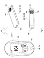
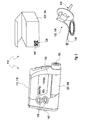
- FIGS. 1 and 2 For example, two different embodiments of medical systems 110 according to the present invention are shown. These medical systems 110 each include a medical device 112, which is the actual function carrier of a main function of the medical system 110. It is exemplary in the embodiment in FIG. 1 the medical device 112 configured as a blood glucose meter 114, whereas the medical device 112 in the embodiment according to FIG. 2 is designed as insulin pump 116. In particular, the medical device 112 may be configured to facilitate interaction with a user.
- input means 118 enable a user to operate mechanical and / or electrical functions of medical device 112.
- output means 120 may be provided, for example one or more displays which, for example, measured values, set parameters or others Allow information to a user.
- the medical device 112 can thus represent the actual "interface" of the medical system 110 to the user.
- the medical system 110 includes one or more medical consumables 122 FIG. 1
- the blood glucose meter 114 interacts with test elements 124, which are shown by way of example in FIG FIG. 1 are shown in two embodiments. While the upper embodiment, designated by the reference numeral 126, shows a rigid test element having a flat, oblong shape, the lower embodiment in FIG FIG. 1 a test strip 128.
- the in FIG. 1 shown glucose meter 114 is typically designed for the use of test strips 128, but other types of test elements, such as the test element 126 can be used.
- Both test elements 124 have an application site 130, on which a sample of a body fluid can be applied to the test element 124. This can be done with test element 124 entered into the blood glucose meter 114 or, in various systems, outside the blood glucose meter.
- the blood glucose meter 114 has an input port 132, which simultaneously serves as a positioning device 134, in order to enable interaction of the blood glucose meter 114 with the test element 124 when the test element 124 is correctly inserted into the input port 132.
- the evaluation of the applied to the application site 130 sample can be done for example by optical or electrochemical means.
- electrode contacts 136 are provided for this purpose, which are contacted by the blood glucose meter 114 when the test strip 128 is inserted into the blood glucose meter 114.
- optical code 138 is indicated only symbolically in the illustrated embodiments and may be configured, for example, as a two-dimensional barcode.
- the code may be a 35-bit code composed of 5 x 7 smallest units. These smallest units are also referred to as modules 140.
- modules 140 In these smallest units, which may be, for example, "white” or "black” in the illustrated embodiment, contain the actual information in, for example, binary form.
- Alternative embodiments are possible, for example by a use of intermediate levels between black and white, that is, grayscale or corresponding color gradations.
- black, white, gray and color apply mutatis mutandis in the entire wavelength range of 300-3000 nm.
- the medical device 112 in the form of the blood glucose meter 114 comprises a code reader 142, which in FIG. 1 is merely indicated.
- This code reader 142 may, for example, be arranged in the vicinity of the input opening 132 within a housing of the blood glucose meter 114, so that in a fixed position with the test element 124 (static measurement) inserted into the positioning device 134 or (dynamically) during the insertion of the test element the optical code 138 can be read by the code reader 142.
- this code reader 142 may be a code reader for 5 ⁇ 7 pixels. Embodiments of the code reader are described in more detail below:
- the test element 124 is to be regarded directly as a medical consumable 122 on which the optical code 138 is applied.
- the optical code 138 may also be arranged, for example, on a medical consumable 122 in the form of a packaging of the test elements 124.
- the code reader 142 may be wholly or partially configured as a code reader mounted on an outside of a housing of the blood glucose meter 114, which is arranged, for example, to read the optical code 138 on that package.
- an insulin cartridge 144 as a medical consumable 122.
- an optical code 138 (in FIG. 2 not shown) are applied to this insulin cartridge 144.
- a primary cartridge for an insulin supply can also be used, with insulin being transferred from this primary cartridge into the insulin cartridge 144.
- the primary cartridge from which insulin is transferred to the insulin cartridge 144 itself, or a package thereof may be coded with an optical code 138 and thus act as a medical consumable 122.
- a medical consumable 122 is shown in the form of an infusion set 146.
- This infusion set 146 includes a cannula 148, which is connectable to an adapter 150 of the insulin pump 116, and the actual cannula 152 for insertion into a body tissue.
- the filling volume of the entire infusion set 146, or portions thereof, is an essential parameter needed for "priming" insulin pump 116.
- an optical code 138 may be provided on the infusion set 146 itself or on a package 154 thereof, which may also be regarded as a medical consumable 122.
- This optical code can in turn be read by the insulin pump 116 by means of a code reader 142 so that the insulin pump 116 can use this information about the filling volume for a priming procedure. Other types of information can be transferred in this way.
- the code reader 142 is in FIG. 2 symbolically arranged at one end of a housing of the insulin pump 116 and can be placed on the packaging 154 and / or the infusion set 146, for example, to read the information onto the optical code 138.
- the code reader 142 comprises an image sensor 156 having a plurality of individual sensors, which in FIG. 3 are not shown resolved.
- these individual sensors can be arranged one-dimensionally or two-dimensionally.
- the image sensor can be configured, for example, as an array of photodiodes, as a CCD chip, as a CMOS chip, as an organic photodetector (OPD) or in a similar manner.
- the image sensor 156 may in particular be arranged on a sensor board 158.
- the code reader 142 comprises a light source 160, for example one or more light-emitting diodes.
- This light source 160 serves to illuminate the optical code 138 on the medical consumable 122 with an illumination light 162.
- this illumination light can also function as an excitation light, whereby, irrespective of the type of interaction, both terms are used interchangeably in the context of the present invention.
- the thus-illuminated optical code 138 is transmitted through an imaging system 164, which is shown in FIG. 3 symbolically represented in the form of a single lens is imaged onto an active sensor surface 166 of the image sensor 156.
- This imaging is done via imaging optical elements, such as lenses or lens systems.
- code readers 142 according to FIG. 3 is a considerable distance (in FIG. 3 denoted by D) between the code reader 142 and the electronic board 158 and the medical consumable 122 required. This is due to the fact that the illumination light 162 laterally on the surface of the optical code 138, which must be uniformly illuminated, and wherein the illumination light 162 may not be hindered by the imaging system 164. Furthermore, the minimum distance, which is usually several millimeters, mit felicit by the imaging system 164, since this must comply with the optical imaging laws. In addition, the requirement of the imaging system 164 significantly increases the cost of the code reader 142. Overall, therefore, a code reader 142 according to FIG. 3 is based on cost considerations and space considerations for portable medical devices 142, for example according to FIGS FIGS. 1 or 2 , with some disadvantages.
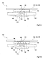
- FIG. 4 a first embodiment of a code reader 142 according to the invention is shown.
- This code reader again uses a medical consumable 122, which is assumed to be a test strip 128 in the following and without limitation of possible further embodiments.
- the test strip 128 in this embodiment comprises a carrier material 168, on which the optical code 138 is applied.
- the optical code 138 is seated on a light-optical fiber board 170 or is positioned immediately in front of this fiber board 170.
- This light-optical fiber plate 170 is arranged directly above the image sensor 156 or is seated on this image sensor 156, but optionally one or more intermediate layers may also be provided.
- the image sensor 156 is in turn arranged, for example, on a sensor board 158 and can be configured, for example, as in FIG FIG. 3 described.
- the carrier material 168 of the test strip 128 is produced wholly or partly from a material that is at least partially transparent to the illumination light 162.
- the light source 160 which is a component of a lighting device 172 with an optional lighting board 174, is arranged in this exemplary embodiment on the rear side of the test strip 128, that is to say on the side of the test strip 128 facing away from the optical code 138.
- the illumination light 162 penetrates the substrate 168 and interacts with the optical code 138. This can be done in various ways. For example, the illuminating light 162 may be absorbed by the material of the optical code 138 to form a shadow image.
- the material of the optical code 138 may also be designed to be luminescent, for example fluorescent, and to excite the optical code for emission of luminescent light.
- the illumination light 162 may also be connected to the carrier material 168, such as a luminescent converter or dye received in this substrate 168, which generates a secondary illumination light 162 which in turn illuminates the optical code 138 from behind. The latter can for example be used to even out the illumination light 162.
- an image of the optical code which is perceptible, is formed on the surface of the optical code 138.
- This image of the optical code 138 is passed through the light-optical fiber board 170 to the active sensor surface 166 of the image sensor 156.
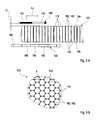
- FIGS. 5A and 5B is a cross-sectional view from the side or in a partial plan view of a light-optical fiber plate 170 exemplified, with reference to which the structure and the operating principle of such an element to be explained.
- the light-optical fiber plate 170 includes a plurality of optical fibers 176, which are preferably as shown in FIG. 5B to recognize, are arranged in close packing next to each other. These optical fibers 176 are glued or fused together.
- the fiber cores 178 may preferably still be completely separated from each other and embedded only in a common matrix 180.
- this matrix 180 may be composed of a cladding (cladding) of the original single optical fibers 176 in the spaces between the fiber cores 178.
- the optical fibers 176 are preferably oriented at least substantially parallel to each other, the orientation may for example be perpendicular to two surfaces 184, 186 of the light-optical fiber plate. These two surfaces include a code-side surface 184 and a sensor-side surface 186.
- the optical fiber panel 170 is based on transporting light from the code-side surface 184 to the sensor-side surface 186 or, conversely, total internal reflection in the optical fibers 176 means, however, that an object located immediately in front of the code-side surface 184, for example the image of the optical code 138, is virtually transported by the light-optical fiber plate 170 to the sensor-side surface 186. This can be explained by the fact that a spot emitter, which is arranged directly in front of this code-side surface 184, is converted by the optical fibers 176 into a virtual spot emitter, which is located on the sensor-side surface 186.
- the image of the optical code 138 can at least theoretically be composed of such point radiators, this means that if this image is arranged on the code-side surface 184 or immediately in front of this code-side surface 184, it is virtually converted into an image on the sensor-side surface 186 becomes.
- FIG. 5A is further illustrated how a preferred spacing between optical code 138 and light optical fiber panel 170 is configured.
- each optical code 138 as shown by FIG. 1 explained as the smallest optical units modules 140.
- the in FIG. 5A The distance between the light-optical fiber plate 170 or its code-side surface 184 and the optical code 138, which is denoted by a 1 , is preferably smaller than one in FIG FIG. 5A a distance between the centers of adjacent modules 140 denoted by a 2 .
- FIG. 5A Also shown symbolically is a preferred relationship between the image sensor 156 and the configuration of the light-optical fiber board 170.
- the image sensor 156 as described above, is composed of a plurality of sensors 188 which, as shown in FIG. 5A indicated, for example, linear or arranged in a two-dimensional matrix.
- the light-optical fiber plate 170 is preferably configured such that at least three such optical fibers 176 are provided per such sensor 188 and per dimension. In a two-dimensional arrangement, therefore, a minimum number of nine optical fibers 176 is preferred. Further increase in the number of optical fibers 176 may lead to an improvement in readout quality.
- the optical fibers 176 preferably have a diameter d (see FIG. 5B ) of less than 100 ⁇ m.
- the embodiment of the code reader 142 according to FIG. 4 requires an arrangement of the illumination device 172 on a rear side of the medical consumable 122.
- This can be implemented, for example, in a test strip 128 inserted into a blood glucose meter 114, since this test strip 128 can be inserted between the illumination device 172 and the sensor board 158.
- this arrangement is disadvantageous because it is usually required that the illumination device 172 and the sensor board 158 form a unit, for example a single electronic module. This is in accordance with the arrangement FIG. 4 difficult to realize.
- FIGS. 6 to 9 Accordingly, embodiments of the code reader 142 are shown, which realize such a configuration and in which the lighting of the optical code 138 is performed by the illumination device 172 substantially from the same side of the medical consumable 122 as the detection by the image sensor 156.
- FIG. 6 an embodiment is shown in which again a light-optical fiber plate 170 rests directly or with only a small distance on the image sensor 156.
- Side of the image sensor 156 are provided at the edge of the light-optical fiber plate 170 and / or in recesses same light sources 160, for example, in turn, light-emitting diodes.
- These light sources 160 irradiate illumination light 162 laterally into the light-optical fiber plate 170, ie at least approximately perpendicular to the longitudinal extent of the optical fibers 176 in the light-optical fiber plate 170 and thus to the viewing direction of the image sensor 156.
- this illumination light 162 can be provided by the cladding 182 and / or the Matrix 180 of the light-optical fiber plate 170 penetrate, so that in total the light-optical fiber plate 170 and thus also the immediately above arranged optical code 138 are illuminated.
- the illumination light 162 can also penetrate into a carrier material 168 of the medical consumable 122, which, for example, can again be designed to be transparent or at least partially light-scattering properties. Accordingly, a detection of the light reflected from the optical code 138 and / or a fluoroscopy of the optical code 138, that is, a detection of the transmitted light, take place.
- the optical code 138 or its modules 140 may also have optical properties such as luminescence properties, conversion properties or the like.
- a luminescent ink may be printed, laser conversion of a dye may be performed, or the like.
- a carrier material 168 with diffusely the illumination light 162 conductive properties for example, a polyester can be used, which may also be provided with a doping, such as a titanium dioxide doping, so that the carrier material 168 still gives a basically white impression.
- one or more additional elements may be provided.
- one or more filters may be provided, for example interference filters and / or edge filters.
- a filter may be provided between the image sensor 156 and the light-optical fiber plate 170 to separate the illumination light 162 from the actual detection light emanating from the optical code 138.
- the latter is particularly advantageous in the case in which optical code 138 or its modules 140 or the ink or color used for these modules 140 are excited by the illumination light 162 to an emission of detection light, which differs spectrally from the illumination light 162. In this way, the contrast and the signal-to-noise ratio of the signal picked up by the image sensor 156 can be significantly improved.
- FIG. 7 is one too FIG. 6 basically similar embodiment of the code reader 142 shown.
- the light sources 160 are arranged laterally adjacent to the light-optical fiber plate 170.
- substantially no coupling of illumination light 162 into the light-optical fiber plate 170 from the side which can be realized for example by a geometric orientation and / or directionality of these light sources 160 and / or by appropriate shielding, for example, opaque color design of the side edges the light-optical fiber plate 170, for example, by blackening.
- the illumination light 162 is scattered in the carrier material 168 of the medical consumable 122, for which purpose this carrier material can in turn be designed accordingly.
- This scattering can take place with an unchanged wavelength, or scattering centers can be provided which have wavelength-converting properties.
- titanium dioxide particles may be provided in the carrier material 168, which may comprise, for example, a transparent plastic, for example a polyester, e.g. Melinex, may include. Due to the scattering properties of these scattering centers, an inhomogeneous intensity distribution arises in the matrix material of the carrier material 168.
- the optical code 138 is thus illuminated from the rear, which produces a required contrast between, for example, black and white modules 140 of this optical code 138.
- an excitation of the optical code 138 by the illumination light 162 can again take place, for example once again an excitation to a luminescence.
- this spectrally altered detection light can also be recorded, for example by a spectral separation in the image sensor 156.
- FIG. 8 is a further embodiment of a code reader 142 is shown, which in turn from the structure in the embodiment according to FIG. 7 is similar, so much to the description of the FIG. 7 can be referenced.
- a code reader 142 is shown, which in turn from the structure in the embodiment according to FIG. 7 is similar, so much to the description of the FIG. 7 can be referenced.
- no coupling of illumination light 162 takes place laterally in the light-optical Fiber board 170, but preferably only a light coupling into a carrier material 168 of the medical consumable 122nd
- illumination light 162 is used, which is spectrally changed in its properties by the optical code 138 or its modules 140 or an ink or color used for these modules.
- short-wavelength light can be used which represents an excitation light.
- a luminescence can be excited in the color or ink of the optical code 138.
- This luminescence light which is shorter wavelength than the excitation light 162, for example due to a Stokes shift, can be separated from the excitation light 162 by suitable spectrally selective elements. Exemplary is for this purpose in the structure according to FIG.
- a filter 190 is provided, which is indeed at least largely transparent to detection light, which, however, at least largely suppresses the excitation light 162.
- This filter 190 may be provided, for example, directly between the light-optical fiber plate 170 and the image sensor 156. Alternatively or additionally, however, other arrangements are possible. In order to avoid that the image quality on the image sensor 156 is degraded by the thickness of the filter 190, thicknesses of only a few 100 ⁇ m or less are preferred for the filter 190.
- a filter coating may be provided directly on the image sensor 156 or its active sensor surface 166. Alternatively or additionally, the image sensor 156 or its sensors 188 may itself also be equipped with spectrally selective properties, for example with a spectral sensitivity only in the region of the detection light to be detected.
- optical code 138 An advantage of using fluorescent ink for the optical code 138 is also that the optical code can be made at least largely invisible to a user. Thus, the optical code 138 can also be used for securing against counterfeiting, since this is not immediately recognizable to a user or possible imitators of the medical consumables 122.
- Figure 9A is another embodiment of a code reader 142 shown schematically, which pursues a third, alternatively or additionally realizable lighting concept. While in FIG. 4 a backside fluoroscopy is done and while in the FIGS. 6 to 8 a lateral illumination is done in the embodiment according to Figure 9A illumination with illumination light 162 passes directly through the light-optical fiber plate 170, wherein the illumination takes place substantially parallel to the longitudinal extent of the optical fibers 176.
- the image sensor 156 is at least substantially transparent to the illumination light 162. For example, this can be done by the image sensor 156 or its sensors 188 having a semiconductor material which has a band gap.
- the illumination light 162 may be chosen such that it has a longer wavelength than the wavelength corresponding to this band gap, so that only a negligible absorption of the illumination light 162 in the image sensor 156 takes place.
- Light-converting materials can then be provided in the carrier material 168 and / or in the material of the optical code 138, which convert this long-wavelength illumination light 162 into correspondingly shorter-wave detection light, which in turn can then be perceived by the image sensor 156.
- the image sensor 156 may also include specifically designed for a light passage areas. This is in FIG. 9B exemplified, which largely the Figure 9A corresponds so that for the description of the structure can be largely referenced to the above description of Figure 9A.
- the transmissive areas in the image sensor 156 can be configured in various ways. For example, these areas can be realized through corresponding openings in the image sensor 156, through which the illumination light 162 can penetrate. Alternatively or additionally, as in the embodiment according to FIG. 9B also uncoated areas may be provided in the image sensor 156, through which the passage of light can take place.
- the latter can be realized, for example, with an array of sensors 188, which are arranged at a distance from one another on a transparent carrier, for example a glass plate. Through the spaces between the individual sensors 188 then excitation light 162 can pass through at least substantially unhindered.
- the illumination light 162 may then in turn interact with the optical code 138 in various ways. For example, here again a reflection, an absorption, a luminescence excitation or the like may be mentioned.
- the ratio between the fraction of an active sensor surface 166 formed by the sensors 188 and the total active sensor surface 166 is generally referred to as a fill factor.
- this fill factor is less than 100% for most image sensors 156. In the context of the present invention, this can not only be tolerated, but can even be deliberately exploited.
- at least part of an electronic system can already be arranged in the intermediate spaces between the sensors 188. For example, this may be part of the electronics required for the evaluation of the signals of the sensors 188, for example a transistor electronics, amplifiers, diodes or combinations of said and / or other elements.
- This electronics can also be configured at least partially transparent. In this case, therefore, at least some of the electronics can already be arranged on and / or directly below the active sensor surface 166, for example in the same layer plane in which the sensors 188 are arranged. As a result, for example, the entire size of the image sensor 156 can again be reduced, and lower-cost image sensors 156, for example semiconductor image sensors, can be used. For example, image sensors 156 having fill factors of about 25% may be used. The disadvantages of low filling factors, which are in particular in a lower luminous efficacy, are not noticeable in image sensors 156 to the same degree as, for example, in camera systems. In this respect, even comparatively small fill factors can be tolerated. In general, for example, as described above, CMOS structures can be used as image sensors 156.
- the sensor board 158 may be provided with an opening 192 into which one or more light sources 160 of the illumination device 172 protrude.
- the at least one light source 160 or such a light source are arranged behind the image sensor 156 are also possible.
- the complete image of the optical code 138 is imaged onto the active sensor surface 166.
- the active sensor surface 166 may be provided with a suitable size.
- Such an enlarging or equally reducing configuration of the light-optical fiber plate 170 is basically also conceivable for other applications than the applications described in the context of the present invention.
- the area of the optical code 138 can be adapted, for example, to the size of the light-optical fiber plate 170, so that it is optimally utilized, for example, and the size and cost thus remain small or small.
- the optical code 138 has repetitive, identical code units 194. These code units 194 are each designed with the same pattern of modules 140, which can be detected. In this way, even if the image sensor 156 detects only a section of the optical code 138, preferably a section comprising at least one complete code unit 194, it is possible to read out the information contained in this optical code 138.
- the evaluation of the information contained in the optical code 138 may already be carried out completely or partially in the code reader 142.
- the image sensor 156 can be equipped with its own intelligence, which already enables a partial or complete evaluation of the optical code 138.
- filters, image recognition algorithms or the like may already be implemented in the image sensor 156.
- a further evaluation is possible in principle.
- the code reader 142 may also include additional electronic components, which further fully or partially realize the evaluation of the optical code 138 for obtaining the at least one information contained therein. These additional components may for example also be arranged on the sensor board 158 or may also be arranged separately.
- a further evaluation can also be undertaken by a control unit of the medical device 112, for example a central control unit of a blood glucose meter 114 or an insulin pump 116.
- a control unit of the medical device 112 for example a central control unit of a blood glucose meter 114 or an insulin pump 116.
- a control unit of the medical device 112 for example a central control unit of
- the illumination of the optical code 138 by means of the illumination device 172 has always been considered static. However, this is not necessarily the case, but it can, alternatively or additionally, also be a time-resolved lighting and / or measurement.
- An embodiment of such a dynamic or time-resolved measurement scheme is in FIG. 11 shown symbolically. Numerous other measuring schemes are possible.
- an intensity 1 of the illumination light 162 is plotted against the time t. From this it can be seen that at a time t 0 an illumination pulse 196 with an intensity I 0 is emitted.
- This illumination pulse 196 may, as in FIG. 11 indicated by dashed lines, for example, stimulate a dye of the optical code 138 to an afterglow 198, which lasts longer than the actual time duration .DELTA.t of the illumination pulse 196.
- this afterglow 198 may include a luminescence or more specifically a phosphorescence here.
- a query of the detection light in the form of the afterglow 198 by the image sensor 156 can take place. This can be done for example by a corresponding "gate" in an electronic control of the image sensor, which is triggered by the illumination pulse 196. Also, this image capture can be what's in FIG. 11 is not shown, again over a certain period of time, so that a sufficient amount of detection light from the image sensor 156 can be recorded. In this way, through the in FIG. 11 shown temporal measurement scheme by an excitation-response measurement method, the illumination light 162 are separated from the detection light in the form of afterglow 198, which can achieve a strong improvement of the signal-to-noise ratio and a background suppression.
- the measurement procedure can also be carried out repeatedly, which is also in FIG. 11 is indicated.
- the illumination pulse 196 may be repeated, for example periodically.
- the measurement scheme can for example be carried out periodically, so that a frequency-selective evaluation by means of a lock-in process can be realized.
- FIG. 12 is one to the FIGS. 4 . 6 to 8 and 9A and 9B alternate embodiment of a code reader 142, which shows an example of a possible positioning device 134 in a schematic representation.
- the code reader 142 can, for example, largely as in the previous embodiments be configured described code reader 142, so that for possible embodiments, for example, to the above description can be referenced.
- a lighting device 172 is in FIG. 12 not shown. The lighting can also be done, for example, again as in the previously described embodiments.
- the positioning device 134 comprises in the in FIG. 12 illustrated embodiment optionally a drawer 200, in which the medical consumable 122 can be inserted.
- these medical consumables 122 may in turn be a test element 124, for example a test strip 128.
- the positioning device 134 can be adapted to the geometric shape of these consumables 122.
- the drawer 200 may be replaced with corresponding other types of brackets or similar devices.
- the positioning device 134 further comprises in the in FIG. 12 illustrated embodiment, a spacer 202.
- This spacer 202 includes, for example, a spacer rail 204 which is adapted to ensure a predetermined minimum distance between the medical consumable 122 and the light-optical fiber plate 170. In this way it can be ensured that the light-optical fiber plate 170 is not damaged, worn or soiled by the medical consumable 122, in particular during the insertion and / or ejection thereof.
- the minimum distance for example, at least largely in the FIG. 5A Correspond to a distance designated a 1 .
- the positioning device 134 in the in FIG. 12 illustrated embodiment optionally a pressure element 206, which is here indicated for example as a spring element 208.
- This pressure element 206 applies a force to the medical consumable 122 in the direction of the light-optical fiber plate 170.
- the medical consumable 122 is pressed against the spacer rail 204, so as to ensure that the distance between the medical consumable 122 and the light-optical fiber plate 170 does not exceed a desired maximum distance.
- the positioning device 134 may be configured to hold the medical consumable 122 at the above-described distance a 1 .
- other embodiments of the positioning device are in principle possible.
Claims (14)
- Système médical (110), comprenant au moins un appareil médical (112) pour accomplir au moins une fonction médicale, notamment un appareil médical (112) configuré en tant qu'appareil manuel, l'appareil médical (112) étant conçu pour, en vue d'accomplir la fonction médicale, coopérer avec au moins un article de consommation médical (122), l'appareil médical (112) présentant au moins un lecteur de code (142) pour lire au moins une information d'un code optique (138) sur l'article de consommation médical (122), le lecteur de code (142) comprenant au moins un capteur d'image (156) doté d'une pluralité de capteurs (188), le lecteur de code (142) comprenant en outre au moins une plaque de fibres optiques (170), la plaque de fibres optiques (170) étant disposée pour guider une image du code optique (138) jusqu'au capteur d'image (156), comprenant en outre au moins un article de consommation médical (122), l'article de consommation médical (122) présentant au moins un code optique (138) pouvant être lu par le lecteur de code (142), le code optique (138) présentant une pluralité de modules (140) lisibles optiquement en tant que plus petites unités d'information, le lecteur de code (142) présentant au moins un dispositif d'éclairage (172), caractérisé en ce que la plaque de fibres optiques (170) est réalisée sous la forme d'une plage plane, la plaque de fibres optiques (170) étant conçue pour transporter de la lumière d'un premier plan de la plaque de fibres optiques (170) vers un deuxième plan de la plaque de fibres optiques (170) sans provoquer ici une modification notable d'une image, le code optique (138) étant un code optique (138) bidimensionnel, l'appareil médical (112) et l'article de consommation médical (122) étant positionnés l'un par rapport à l'autre dans une position de lecture dans laquelle le lecteur de code (142) peut lire l'information du code optique (138) bidimensionnel de l'article de consommation médical (122) de telle sorte qu'un écart entre la plaque de fibres optiques (170) et le code optique (138) est inférieur à un écart entre les points centraux des modules (140) voisins du code (138), le dispositif d'éclairage (172) étant conçu pour éclairer le code optique (138) de l'article de consommation (122) d'un côté depuis le même côté sur lequel est également prévu le capteur d'image (156), le dispositif d'éclairage (172) étant configuré d'au moins l'une des manières suivantes :- le dispositif d'éclairage (172) est conçu pour éclairer le code optique (138) à travers la plaque de fibres optiques (170) ;- le dispositif d'éclairage (172) est conçu pour éclairer le code optique (138) par le côté, de préférence pour l'essentiel perpendiculairement à un sens d'observation de la plaque de fibres optiques (170), notamment à travers un matériau porteur (168) de l'article de consommation médical (122) ;- le dispositif d'éclairage (172) comprend au moins une source de lumière (160), la source de lumière (160) étant conçue pour éclairer l'article de consommation médical (122) dans la zone du code optique (138) à travers le capteur d'image (156).
- Système médical (110) selon la revendication précédente, avec lequel la plaque de fibres optiques (170) présente une pluralité de fibres optiques (176) ayant un diamètre inférieur à 100 micromètres.
- Système médical (110) selon l'une des revendications précédentes, avec lequel le lecteur de code (142) présente au moins un dispositif d'éclairage (172), le dispositif d'éclairage (172) incluant au moins une source de lumière (160) qui est conçue pour éclairer par transparence l'article de consommation médical (122) dans la zone du code optique (138).
- Système médical (110) selon l'une des revendications précédentes, avec lequel le lecteur de code (142) présente au moins un dispositif d'éclairage (172), le dispositif d'éclairage (172) étant conçu pour éclairer l'article de consommation médical (122) avec de la lumière à différentes longueurs d'onde, notamment séquentiellement.
- Système médical (110) selon l'une des revendications précédentes, avec lequel le lecteur de code (142) présente au moins un dispositif d'éclairage (172), le lecteur de code (142) étant conçu pour capturer l'image du code optique (138) avec un retard dans le temps par rapport à un éclairage par le dispositif d'éclairage (172).
- Système médical (110) selon l'une des revendications précédentes, avec lequel l'appareil médical (112) comprend au moins l'un des appareils suivants :- un appareil d'analyse (114) pour déceler au moins un analyte dans un échantillon, notamment un appareil d'analyse (114) pour déceler au moins un métabolite dans un fluide corporel, l'appareil d'analyse (114) étant conçu pour coopérer avec un article de consommation médical (122) sous la forme d'au moins un élément de test (124) pour déceler l'analyte, notamment une plaquette de test (128) ou une bande de test ;- un dispositif de dosage pour doser au moins un médicament, notamment une pompe à insuline (116), le dispositif de dosage étant conçu pour coopérer avec un article de consommation (122) sous la forme d'un cathéter et/ou d'une canule (148, 152), l'information comprenant de préférence une information sur un volume de remplissage du cathéter et/ou de la canule (148, 152).
- Système médical (110) selon l'une des revendications précédentes, avec lequel le capteur d'image (156) présente au moins deux zones ayant des sensibilités spectrales différentes.
- Système médical (110) selon l'une des revendications précédentes, comprenant en outre un dispositif de positionnement (134) qui est conçu pour positionner l'appareil médical (112) et l'article de consommation (122) l'un par rapport à l'autre.
- Système médical (110) selon l'une des revendications précédentes, comprenant au moins un article de consommation médical (122), l'article de consommation médical (122) présentant au moins un code optique (138) lisible par le lecteur de code (142), le code optique (138) présentant une pluralité de modules (140) lisibles optiquement en tant que plus petites unités d'information, la plaque de fibres optiques (170) étant dimensionnée de telle sorte qu'au moins trois fibres optiques (176) sont prévues par module (140) par dimension du code optique (138).
- Système médical (110) selon l'une des revendications précédentes, comprenant au moins un article de consommation médical (122), l'article de consommation médical (122) présentant au moins un code optique (138) lisible par le lecteur de code (142), l'article de consommation médical (122) comprenant dans la zone du code optique (138) un matériau porteur (168), le matériau porteur (168) présentant des propriétés transparentes ou de diffusion de la lumière, le matériau porteur (168) comprenant de préférence une matière plastique transparente, notamment un polyester, notamment du Melinex.
- Système médical (110) selon l'une des revendications précédentes, comprenant au moins un article de consommation médical (122), l'article de consommation médical (122) présentant au moins un code optique (138) lisible par le lecteur de code (142), le code optique (138) étant conçu pour interagir différemment avec de la lumière à différentes longueurs d'onde.
- Système médical (110) selon l'une des revendications précédentes, comprenant au moins un article de consommation médical (122), l'article de consommation médical (122) présentant au moins un code optique (138) lisible par le lecteur de code (142), le code optique (138) présentant au moins partiellement des propriétés luminescentes, le code optique (138) présentant de préférence une pluralité de modules (140) lisibles optiquement en tant que plus petites unités d'information, le code optique (138), notamment les modules (140) du code optique (138), incluant de préférence au moins un convertisseur de lumière, notamment un phosphore, le convertisseur de lumière étant conçu pour convertir une lumière d'excitation en une lumière ayant une longueur d'onde différente de celle de la lumière d'excitation, notamment en une lumière ayant une longueur d'onde plus longue que celle de la lumière d'excitation.
- Système médical (110) selon la revendication précédente, avec lequel la matière plastique transparente est dopée avec du TiO2 de telle sorte qu'il se produit une impression globale essentiellement blanche du matériau porteur (168), le matériau porteur (168) présentant des propriétés de conduction diffuse de la lumière.
- Système médical (110) selon l'une des revendications précédentes, comprenant au moins un article de consommation médical (122), l'article de consommation médical (122) présentant au moins un code optique (138) lisible par le lecteur de code (142), l'article de consommation médical (122) comprenant dans la zone du code optique (138) un support avec un matériau porteur (168), le support comprenant en outre au moins un convertisseur de lumière, le convertisseur de lumière étant conçu pour convertir une lumière d'excitation en une lumière ayant une longueur d'onde différente de celle de la lumière d'excitation.
Priority Applications (1)
| Application Number | Priority Date | Filing Date | Title |
|---|---|---|---|
| EP09781580.7A EP2317909B1 (fr) | 2008-08-06 | 2009-08-06 | Système médical avec lecteur de codes-barres compact pour consommables |
Applications Claiming Priority (3)
| Application Number | Priority Date | Filing Date | Title |
|---|---|---|---|
| EP08161928 | 2008-08-06 | ||
| PCT/EP2009/060237 WO2010015689A1 (fr) | 2008-08-06 | 2009-08-06 | Système médical avec lecteur de codes-barres compact pour consommables |
| EP09781580.7A EP2317909B1 (fr) | 2008-08-06 | 2009-08-06 | Système médical avec lecteur de codes-barres compact pour consommables |
Publications (2)
| Publication Number | Publication Date |
|---|---|
| EP2317909A1 EP2317909A1 (fr) | 2011-05-11 |
| EP2317909B1 true EP2317909B1 (fr) | 2014-09-17 |
Family
ID=41147487
Family Applications (1)
| Application Number | Title | Priority Date | Filing Date |
|---|---|---|---|
| EP09781580.7A Active EP2317909B1 (fr) | 2008-08-06 | 2009-08-06 | Système médical avec lecteur de codes-barres compact pour consommables |
Country Status (7)
| Country | Link |
|---|---|
| US (1) | US9282922B2 (fr) |
| EP (1) | EP2317909B1 (fr) |
| JP (1) | JP2011530129A (fr) |
| KR (1) | KR101243413B1 (fr) |
| CN (1) | CN102112048B (fr) |
| CA (1) | CA2730000A1 (fr) |
| WO (1) | WO2010015689A1 (fr) |
Families Citing this family (11)
| Publication number | Priority date | Publication date | Assignee | Title |
|---|---|---|---|---|
| CA2730000A1 (fr) * | 2008-08-06 | 2010-02-11 | F. Hoffmann La-Roche Ag | Systeme medical avec lecteur de codes-barres compact pour consommables |
| EP2988801B1 (fr) * | 2013-04-22 | 2019-02-20 | Sanofi-Aventis Deutschland GmbH | Dispositif de capteur destiné à être fixé à un dispositif d'administration de médicament |
| US20150099307A1 (en) * | 2013-10-07 | 2015-04-09 | Texas Instruments Incorporaated | Glucose test strip authentication using ink |
| DE102014103633B4 (de) * | 2014-03-17 | 2017-07-27 | ConnectMeSmart GmbH | Vorrichtung zur Interaktion mit einem mobilen Endgerät |
| JP2015212685A (ja) * | 2014-04-15 | 2015-11-26 | アークレイ株式会社 | センサおよび測定装置 |
| US10628736B2 (en) | 2015-09-24 | 2020-04-21 | Huron Technologies International Inc. | Systems and methods for barcode annotations for digital images |
| JP6910355B2 (ja) | 2015-12-10 | 2021-07-28 | サノフィ−アベンティス・ドイチュラント・ゲゼルシャフト・ミット・ベシュレンクテル・ハフツング | 取り外し可能に取り付け可能なセンサデバイスを備える薬物送達デバイス |
| US11042772B2 (en) | 2018-03-29 | 2021-06-22 | Huron Technologies International Inc. | Methods of generating an encoded representation of an image and systems of operating thereof |
| CA3118014A1 (fr) | 2018-11-05 | 2020-05-14 | Hamid Reza Tizhoosh | Systemes et procedes de gestion d'images medicales |
| EP4252190A1 (fr) | 2020-11-24 | 2023-10-04 | Huron Technologies International Inc. | Systèmes et procédés de génération de représentations codées pour de multiples grossissements de données d'image |
| CN114047168A (zh) * | 2021-11-16 | 2022-02-15 | 江苏硕世生物科技股份有限公司 | 基于光学的试剂卡识别检测系统及方法 |
Family Cites Families (53)
| Publication number | Priority date | Publication date | Assignee | Title |
|---|---|---|---|---|
| US4141624A (en) * | 1977-11-21 | 1979-02-27 | American Optical Corporation | Dynamic image enhancement for fiberscopes |
| FR2502779A1 (fr) * | 1981-03-26 | 1982-10-01 | Lre Relais & Elektronik Gmbh | Appareil de mesure permettant l'analyse opto-electronique de bandes de papier reactif |
| DE3133826A1 (de) * | 1981-08-27 | 1983-03-10 | Boehringer Mannheim Gmbh, 6800 Mannheim | Analyseteststreifen und verfahren zu seiner herstellung |
| DE3137174A1 (de) * | 1981-09-18 | 1983-04-07 | Boehringer Mannheim Gmbh, 6800 Mannheim | Vorrichtung zur optischen erkennung einer codierung auf einem diagnoseteststreifen |
| JPS6297894A (ja) * | 1985-10-24 | 1987-05-07 | 杉本 治江 | 識別コ−ド付き名刺及びそれを光学的に読取る方法並びに装置 |
| JPH0537718A (ja) * | 1991-07-29 | 1993-02-12 | T T T Kk | 長尺密着イメージセンサ |
| JPH08212286A (ja) * | 1995-02-08 | 1996-08-20 | Olympus Optical Co Ltd | 情報再生システム |
| US5742718A (en) * | 1996-08-13 | 1998-04-21 | Eclipse Surgical Technologies, Inc. | Proprietary fiber connector and electronic security system |
| JPH1086563A (ja) * | 1996-09-11 | 1998-04-07 | Dainippon Printing Co Ltd | 認識用マーク、マーク記録体、及びマーク認識方法 |
| US5714123A (en) * | 1996-09-30 | 1998-02-03 | Lifescan, Inc. | Protective shield for a blood glucose strip |
| US6168957B1 (en) | 1997-06-25 | 2001-01-02 | Lifescan, Inc. | Diagnostic test strip having on-strip calibration |
| US6394952B1 (en) * | 1998-02-03 | 2002-05-28 | Adeza Biomedical Corporation | Point of care diagnostic systems |
| US6372895B1 (en) * | 2000-07-07 | 2002-04-16 | 3M Innovative Properties Company | Fluorogenic compounds |
| US6685678B2 (en) * | 2000-03-22 | 2004-02-03 | Docusys, Inc. | Drug delivery and monitoring system |
| JP2003016198A (ja) * | 2001-06-29 | 2003-01-17 | Aisin Engineering Kk | 医療管理システム |
| JP2003085537A (ja) | 2001-09-07 | 2003-03-20 | Matsushita Electric Ind Co Ltd | 光学式指紋・画像認識装置および方法 |
| US6588670B2 (en) * | 2001-10-30 | 2003-07-08 | Symbol Technologies, Inc. | Medical diagnostic monitoring |
| JP3858263B2 (ja) * | 2001-11-09 | 2006-12-13 | 日本電気株式会社 | 指紋画像入力装置及びそれを用いた電子機器 |
| US7241629B2 (en) * | 2001-12-20 | 2007-07-10 | Corning Incorporated | Detectable labels, methods of manufacture and use |
| US7742088B2 (en) | 2002-11-19 | 2010-06-22 | Fujifilm Corporation | Image sensor and digital camera |
| JP4264248B2 (ja) * | 2002-11-19 | 2009-05-13 | 富士フイルム株式会社 | カラー固体撮像装置 |
| US20050154277A1 (en) * | 2002-12-31 | 2005-07-14 | Jing Tang | Apparatus and methods of using built-in micro-spectroscopy micro-biosensors and specimen collection system for a wireless capsule in a biological body in vivo |
| KR20060079227A (ko) | 2003-09-18 | 2006-07-05 | 코닌클리케 필립스 일렉트로닉스 엔.브이. | 정보매체와, 그 정보매체에 저장된 데이터 판독 시스템 |
| JP2005115495A (ja) * | 2003-10-03 | 2005-04-28 | Win International Co Ltd | カテ室管理システム及びカテ室管理方法 |
| US20080200788A1 (en) * | 2006-10-04 | 2008-08-21 | Dexcorn, Inc. | Analyte sensor |
| CN2700954Y (zh) * | 2003-12-26 | 2005-05-18 | 深圳矽感科技有限公司 | 插卡式条码识读设备 |
| US20060081257A1 (en) * | 2004-08-31 | 2006-04-20 | Ross Krogh | Single use drug delivery components |
| US7419098B2 (en) * | 2004-11-02 | 2008-09-02 | The Code Corporation | Graphical code reading apparatus for reading codes on reflective surfaces |
| US20080088731A1 (en) | 2005-01-20 | 2008-04-17 | Yasuhiro Tanaka | Lens Array and Image Sensor Including Lens Array |
| JP4604160B2 (ja) * | 2005-03-03 | 2010-12-22 | 独立行政法人 国立印刷局 | 認証媒体の作製方法及びその認証方法 |
| US20090065583A1 (en) * | 2005-03-11 | 2009-03-12 | Mcgrew Stephen P | Retro-emissive markings |
| US20060202104A1 (en) | 2005-03-14 | 2006-09-14 | Microalign Technologies, Inc. | Contact-type monolithic image sensor |
| US20060213994A1 (en) | 2005-03-22 | 2006-09-28 | Faiz Tariq N | Barcode reading apparatus and method therefor |
| US20090116753A1 (en) * | 2005-09-12 | 2009-05-07 | Ultradots, Inc. | Authenticating and identifying objects using nanoparticles |
| US20070167694A1 (en) * | 2005-12-21 | 2007-07-19 | Everest Biomedical Instruments Co. | Integrated Portable Anesthesia and Sedation Monitoring Apparatus |
| GB2438669A (en) * | 2006-03-07 | 2007-12-05 | Inverness Medical Switzerland | Sensing apparatus having a pair of coils and an oscillating member |
| WO2007128144A1 (fr) | 2006-05-10 | 2007-11-15 | F. Hoffmann-La Roche Ag | Ensemble de perfusion doté d'un dispositif d'enregistrement de données |
| JP2007323373A (ja) * | 2006-06-01 | 2007-12-13 | Junko Adachi | 医療消耗品管理システム |
| US8126728B2 (en) * | 2006-10-24 | 2012-02-28 | Medapps, Inc. | Systems and methods for processing and transmittal of medical data through an intermediary device |
| DE102006057374A1 (de) * | 2006-12-04 | 2008-06-05 | Francotyp-Postalia Gmbh | Verfahren zur Einstellung der Relativgeschwindigkeit zwischen einem Druckkopf und einem Aufzeichnungsträger in einer Thermotransferdruckvorrichtung |
| WO2008089184A2 (fr) * | 2007-01-15 | 2008-07-24 | Deka Products Limited Partnership | Dispositif et procédé de gestion des aliments |
| US20090157064A1 (en) * | 2007-05-11 | 2009-06-18 | Hodel Michael R | RFID System and Method Therefor |
| EP2040073A1 (fr) * | 2007-09-20 | 2009-03-25 | Iline Microsystems, S.L. | Dispositif microfluidique et procédé pour la détermination du temps de coagulation d'un fluide |
| KR20090046179A (ko) * | 2007-11-05 | 2009-05-11 | 주식회사 동부하이텍 | 투명 박막 트랜지스터, 이미지 센서 및 투명 박막트랜지스터의 제조 방법 |
| US8509879B2 (en) * | 2007-11-06 | 2013-08-13 | The Regents Of The University Of California | Apparatus and method for widefield functional imaging (WiFI) using integrated structured illumination and laser speckle imaging |
| US20090204009A1 (en) * | 2008-02-07 | 2009-08-13 | Los Alamos National Security | Medical device system and related methods for diagnosing abnormal medical conditions based on in-vivo optical properties of tissue |
| US8576354B2 (en) * | 2008-06-26 | 2013-11-05 | American Panel Corporation | Channelized plate |
| KR101260136B1 (ko) * | 2008-08-04 | 2013-05-02 | 에프. 호프만-라 로슈 아게 | 의료 아이템을 인코딩하는 인코딩 방법 |
| CA2730000A1 (fr) * | 2008-08-06 | 2010-02-11 | F. Hoffmann La-Roche Ag | Systeme medical avec lecteur de codes-barres compact pour consommables |
| JP2013505491A (ja) * | 2009-09-17 | 2013-02-14 | エフ.ホフマン−ラ ロシュ アーゲー | 医療消耗品のための高密度バーコード |
| GB2483077A (en) * | 2010-08-25 | 2012-02-29 | Concateno Uk Ltd | Sample testing assay apparatus and method |
| AU2011308615B2 (en) * | 2010-10-01 | 2015-02-05 | Hologic, Inc. | Immunoassay test strip for use in a diagnostic system |
| US9241663B2 (en) * | 2012-09-05 | 2016-01-26 | Jana Care Inc. | Portable medical diagnostic systems and methods using a mobile device |
-
2009
- 2009-08-06 CA CA2730000A patent/CA2730000A1/fr not_active Abandoned
- 2009-08-06 JP JP2011521590A patent/JP2011530129A/ja not_active Ceased
- 2009-08-06 EP EP09781580.7A patent/EP2317909B1/fr active Active
- 2009-08-06 WO PCT/EP2009/060237 patent/WO2010015689A1/fr active Application Filing
- 2009-08-06 KR KR1020117002617A patent/KR101243413B1/ko not_active IP Right Cessation
- 2009-08-06 CN CN2009801304092A patent/CN102112048B/zh not_active Expired - Fee Related
-
2011
- 2011-02-04 US US13/021,382 patent/US9282922B2/en not_active Expired - Fee Related
Also Published As
| Publication number | Publication date |
|---|---|
| JP2011530129A (ja) | 2011-12-15 |
| US20120043377A1 (en) | 2012-02-23 |
| KR20110026512A (ko) | 2011-03-15 |
| CA2730000A1 (fr) | 2010-02-11 |
| US9282922B2 (en) | 2016-03-15 |
| CN102112048A (zh) | 2011-06-29 |
| CN102112048B (zh) | 2013-12-11 |
| WO2010015689A1 (fr) | 2010-02-11 |
| KR101243413B1 (ko) | 2013-03-13 |
| EP2317909A1 (fr) | 2011-05-11 |
Similar Documents
| Publication | Publication Date | Title |
|---|---|---|
| EP2317909B1 (fr) | Système médical avec lecteur de codes-barres compact pour consommables | |
| WO2011033013A1 (fr) | Codes à barres à haute densité pour consommables médicaux | |
| EP2221608B1 (fr) | Procédé de test destiné à examiner un liquide corporel | |
| DE102007003341B4 (de) | Okularsensor und Messsystem zum Nachweis eines Analyten in einer Augenflüssigkeit | |
| EP2317911B1 (fr) | Mesure transcutanée d'une fonction organique | |
| DE602004011471T2 (de) | Optoelektronische Vorrichtung zum schnellen diagnostischen Assay | |
| EP2040079B1 (fr) | Procédé de marquage destiné au marquage de déchet d'éléments test | |
| AT504919B1 (de) | Durchlichtmessvorrichtung | |
| WO2006106084A1 (fr) | Systeme de diagnostic optique mobile | |
| DE102006029987A1 (de) | Optoelektronisches Halbeinwegschnelldiagnosetestsystem | |
| EP2794909B1 (fr) | Procédé de détermination d'une concentration d'analyte | |
| EP2310980A1 (fr) | Procédé de codage d articles médicaux | |
| EP2652479B1 (fr) | Système de mesure pour l'évaluation optique quantitative d'une réaction chimique | |
| DE102018218122B4 (de) | Vorrichtung und Verfahren zur Analyse biologischer, chemischer und biochemischer Substanzen | |
| EP2406638B1 (fr) | Procédé et appareil de fabrication d'un moyen de consommation analytique | |
| EP2825868B1 (fr) | Système de test et procédé de contrôle de l'orientation d'une bandelette de test |
Legal Events
| Date | Code | Title | Description |
|---|---|---|---|
| PUAI | Public reference made under article 153(3) epc to a published international application that has entered the european phase |
Free format text: ORIGINAL CODE: 0009012 |
|
| 17P | Request for examination filed |
Effective date: 20110222 |
|
| AK | Designated contracting states |
Kind code of ref document: A1 Designated state(s): AT BE BG CH CY CZ DE DK EE ES FI FR GB GR HR HU IE IS IT LI LT LU LV MC MK MT NL NO PL PT RO SE SI SK SM TR |
|
| AX | Request for extension of the european patent |
Extension state: AL BA RS |
|
| RIN1 | Information on inventor provided before grant (corrected) |
Inventor name: HAAR, HANS-PETER Inventor name: KOCHERSCHEIDT, GERRIT |
|
| DAX | Request for extension of the european patent (deleted) | ||
| GRAP | Despatch of communication of intention to grant a patent |
Free format text: ORIGINAL CODE: EPIDOSNIGR1 |
|
| INTG | Intention to grant announced |
Effective date: 20140219 |
|
| GRAS | Grant fee paid |
Free format text: ORIGINAL CODE: EPIDOSNIGR3 |
|
| GRAA | (expected) grant |
Free format text: ORIGINAL CODE: 0009210 |
|
| AK | Designated contracting states |
Kind code of ref document: B1 Designated state(s): AT BE BG CH CY CZ DE DK EE ES FI FR GB GR HR HU IE IS IT LI LT LU LV MC MK MT NL NO PL PT RO SE SI SK SM TR |
|
| REG | Reference to a national code |
Ref country code: GB Ref legal event code: FG4D Free format text: NOT ENGLISH |
|
| REG | Reference to a national code |
Ref country code: CH Ref legal event code: EP |
|
| REG | Reference to a national code |
Ref country code: IE Ref legal event code: FG4D Free format text: LANGUAGE OF EP DOCUMENT: GERMAN |
|
| REG | Reference to a national code |
Ref country code: AT Ref legal event code: REF Ref document number: 687296 Country of ref document: AT Kind code of ref document: T Effective date: 20141015 |
|
| REG | Reference to a national code |
Ref country code: DE Ref legal event code: R096 Ref document number: 502009009988 Country of ref document: DE Effective date: 20141030 |
|
| PG25 | Lapsed in a contracting state [announced via postgrant information from national office to epo] |
Ref country code: GR Free format text: LAPSE BECAUSE OF FAILURE TO SUBMIT A TRANSLATION OF THE DESCRIPTION OR TO PAY THE FEE WITHIN THE PRESCRIBED TIME-LIMIT Effective date: 20141218 Ref country code: FI Free format text: LAPSE BECAUSE OF FAILURE TO SUBMIT A TRANSLATION OF THE DESCRIPTION OR TO PAY THE FEE WITHIN THE PRESCRIBED TIME-LIMIT Effective date: 20140917 Ref country code: SE Free format text: LAPSE BECAUSE OF FAILURE TO SUBMIT A TRANSLATION OF THE DESCRIPTION OR TO PAY THE FEE WITHIN THE PRESCRIBED TIME-LIMIT Effective date: 20140917 Ref country code: LT Free format text: LAPSE BECAUSE OF FAILURE TO SUBMIT A TRANSLATION OF THE DESCRIPTION OR TO PAY THE FEE WITHIN THE PRESCRIBED TIME-LIMIT Effective date: 20140917 Ref country code: NO Free format text: LAPSE BECAUSE OF FAILURE TO SUBMIT A TRANSLATION OF THE DESCRIPTION OR TO PAY THE FEE WITHIN THE PRESCRIBED TIME-LIMIT Effective date: 20141217 |
|
| REG | Reference to a national code |
Ref country code: NL Ref legal event code: VDEP Effective date: 20140917 |
|
| REG | Reference to a national code |
Ref country code: LT Ref legal event code: MG4D |
|
| PG25 | Lapsed in a contracting state [announced via postgrant information from national office to epo] |
Ref country code: HR Free format text: LAPSE BECAUSE OF FAILURE TO SUBMIT A TRANSLATION OF THE DESCRIPTION OR TO PAY THE FEE WITHIN THE PRESCRIBED TIME-LIMIT Effective date: 20140917 Ref country code: CY Free format text: LAPSE BECAUSE OF FAILURE TO SUBMIT A TRANSLATION OF THE DESCRIPTION OR TO PAY THE FEE WITHIN THE PRESCRIBED TIME-LIMIT Effective date: 20140917 Ref country code: LV Free format text: LAPSE BECAUSE OF FAILURE TO SUBMIT A TRANSLATION OF THE DESCRIPTION OR TO PAY THE FEE WITHIN THE PRESCRIBED TIME-LIMIT Effective date: 20140917 |
|
| PG25 | Lapsed in a contracting state [announced via postgrant information from national office to epo] |
Ref country code: NL Free format text: LAPSE BECAUSE OF FAILURE TO SUBMIT A TRANSLATION OF THE DESCRIPTION OR TO PAY THE FEE WITHIN THE PRESCRIBED TIME-LIMIT Effective date: 20140917 |
|
| PG25 | Lapsed in a contracting state [announced via postgrant information from national office to epo] |
Ref country code: SK Free format text: LAPSE BECAUSE OF FAILURE TO SUBMIT A TRANSLATION OF THE DESCRIPTION OR TO PAY THE FEE WITHIN THE PRESCRIBED TIME-LIMIT Effective date: 20140917 Ref country code: RO Free format text: LAPSE BECAUSE OF FAILURE TO SUBMIT A TRANSLATION OF THE DESCRIPTION OR TO PAY THE FEE WITHIN THE PRESCRIBED TIME-LIMIT Effective date: 20140917 Ref country code: CZ Free format text: LAPSE BECAUSE OF FAILURE TO SUBMIT A TRANSLATION OF THE DESCRIPTION OR TO PAY THE FEE WITHIN THE PRESCRIBED TIME-LIMIT Effective date: 20140917 Ref country code: ES Free format text: LAPSE BECAUSE OF FAILURE TO SUBMIT A TRANSLATION OF THE DESCRIPTION OR TO PAY THE FEE WITHIN THE PRESCRIBED TIME-LIMIT Effective date: 20140917 Ref country code: IS Free format text: LAPSE BECAUSE OF FAILURE TO SUBMIT A TRANSLATION OF THE DESCRIPTION OR TO PAY THE FEE WITHIN THE PRESCRIBED TIME-LIMIT Effective date: 20150117 Ref country code: EE Free format text: LAPSE BECAUSE OF FAILURE TO SUBMIT A TRANSLATION OF THE DESCRIPTION OR TO PAY THE FEE WITHIN THE PRESCRIBED TIME-LIMIT Effective date: 20140917 Ref country code: PT Free format text: LAPSE BECAUSE OF FAILURE TO SUBMIT A TRANSLATION OF THE DESCRIPTION OR TO PAY THE FEE WITHIN THE PRESCRIBED TIME-LIMIT Effective date: 20150119 |
|
| PG25 | Lapsed in a contracting state [announced via postgrant information from national office to epo] |
Ref country code: PL Free format text: LAPSE BECAUSE OF FAILURE TO SUBMIT A TRANSLATION OF THE DESCRIPTION OR TO PAY THE FEE WITHIN THE PRESCRIBED TIME-LIMIT Effective date: 20140917 |
|
| REG | Reference to a national code |
Ref country code: DE Ref legal event code: R097 Ref document number: 502009009988 Country of ref document: DE |
|
| PLBE | No opposition filed within time limit |
Free format text: ORIGINAL CODE: 0009261 |
|
| STAA | Information on the status of an ep patent application or granted ep patent |
Free format text: STATUS: NO OPPOSITION FILED WITHIN TIME LIMIT |
|
| PG25 | Lapsed in a contracting state [announced via postgrant information from national office to epo] |
Ref country code: DK Free format text: LAPSE BECAUSE OF FAILURE TO SUBMIT A TRANSLATION OF THE DESCRIPTION OR TO PAY THE FEE WITHIN THE PRESCRIBED TIME-LIMIT Effective date: 20140917 |
|
| 26N | No opposition filed |
Effective date: 20150618 |
|
| PG25 | Lapsed in a contracting state [announced via postgrant information from national office to epo] |
Ref country code: SI Free format text: LAPSE BECAUSE OF FAILURE TO SUBMIT A TRANSLATION OF THE DESCRIPTION OR TO PAY THE FEE WITHIN THE PRESCRIBED TIME-LIMIT Effective date: 20140917 |
|
| PG25 | Lapsed in a contracting state [announced via postgrant information from national office to epo] |
Ref country code: LU Free format text: LAPSE BECAUSE OF FAILURE TO SUBMIT A TRANSLATION OF THE DESCRIPTION OR TO PAY THE FEE WITHIN THE PRESCRIBED TIME-LIMIT Effective date: 20150806 Ref country code: MC Free format text: LAPSE BECAUSE OF FAILURE TO SUBMIT A TRANSLATION OF THE DESCRIPTION OR TO PAY THE FEE WITHIN THE PRESCRIBED TIME-LIMIT Effective date: 20140917 |
|
| REG | Reference to a national code |
Ref country code: CH Ref legal event code: PL |
|
| REG | Reference to a national code |
Ref country code: DE Ref legal event code: R081 Ref document number: 502009009988 Country of ref document: DE Owner name: ROCHE DIABETES CARE GMBH, DE Free format text: FORMER OWNER: ROCHE DIAGNOSTICS GMBH, 68305 MANNHEIM, DE |
|
| PG25 | Lapsed in a contracting state [announced via postgrant information from national office to epo] |
Ref country code: CH Free format text: LAPSE BECAUSE OF NON-PAYMENT OF DUE FEES Effective date: 20150831 Ref country code: LI Free format text: LAPSE BECAUSE OF NON-PAYMENT OF DUE FEES Effective date: 20150831 |
|
| REG | Reference to a national code |
Ref country code: IE Ref legal event code: MM4A |
|
| REG | Reference to a national code |
Ref country code: FR Ref legal event code: PLFP Year of fee payment: 8 |
|
| PG25 | Lapsed in a contracting state [announced via postgrant information from national office to epo] |
Ref country code: IE Free format text: LAPSE BECAUSE OF NON-PAYMENT OF DUE FEES Effective date: 20150806 |
|
| REG | Reference to a national code |
Ref country code: AT Ref legal event code: MM01 Ref document number: 687296 Country of ref document: AT Kind code of ref document: T Effective date: 20150806 |
|
| PG25 | Lapsed in a contracting state [announced via postgrant information from national office to epo] |
Ref country code: AT Free format text: LAPSE BECAUSE OF NON-PAYMENT OF DUE FEES Effective date: 20150806 |
|
| PG25 | Lapsed in a contracting state [announced via postgrant information from national office to epo] |
Ref country code: MT Free format text: LAPSE BECAUSE OF FAILURE TO SUBMIT A TRANSLATION OF THE DESCRIPTION OR TO PAY THE FEE WITHIN THE PRESCRIBED TIME-LIMIT Effective date: 20140917 |
|
| PG25 | Lapsed in a contracting state [announced via postgrant information from national office to epo] |
Ref country code: SM Free format text: LAPSE BECAUSE OF FAILURE TO SUBMIT A TRANSLATION OF THE DESCRIPTION OR TO PAY THE FEE WITHIN THE PRESCRIBED TIME-LIMIT Effective date: 20140917 Ref country code: HU Free format text: LAPSE BECAUSE OF FAILURE TO SUBMIT A TRANSLATION OF THE DESCRIPTION OR TO PAY THE FEE WITHIN THE PRESCRIBED TIME-LIMIT; INVALID AB INITIO Effective date: 20090806 Ref country code: BG Free format text: LAPSE BECAUSE OF FAILURE TO SUBMIT A TRANSLATION OF THE DESCRIPTION OR TO PAY THE FEE WITHIN THE PRESCRIBED TIME-LIMIT Effective date: 20140917 |
|
| REG | Reference to a national code |
Ref country code: FR Ref legal event code: PLFP Year of fee payment: 9 |
|
| PG25 | Lapsed in a contracting state [announced via postgrant information from national office to epo] |
Ref country code: BE Free format text: LAPSE BECAUSE OF NON-PAYMENT OF DUE FEES Effective date: 20150831 |
|
| PG25 | Lapsed in a contracting state [announced via postgrant information from national office to epo] |
Ref country code: TR Free format text: LAPSE BECAUSE OF FAILURE TO SUBMIT A TRANSLATION OF THE DESCRIPTION OR TO PAY THE FEE WITHIN THE PRESCRIBED TIME-LIMIT Effective date: 20140917 |
|
| PG25 | Lapsed in a contracting state [announced via postgrant information from national office to epo] |
Ref country code: MK Free format text: LAPSE BECAUSE OF FAILURE TO SUBMIT A TRANSLATION OF THE DESCRIPTION OR TO PAY THE FEE WITHIN THE PRESCRIBED TIME-LIMIT Effective date: 20140917 |
|
| REG | Reference to a national code |
Ref country code: FR Ref legal event code: PLFP Year of fee payment: 10 |
|
| PGFP | Annual fee paid to national office [announced via postgrant information from national office to epo] |
Ref country code: IT Payment date: 20220810 Year of fee payment: 14 Ref country code: GB Payment date: 20220726 Year of fee payment: 14 Ref country code: DE Payment date: 20220615 Year of fee payment: 14 |
|
| PGFP | Annual fee paid to national office [announced via postgrant information from national office to epo] |
Ref country code: FR Payment date: 20220713 Year of fee payment: 14 |
|
| REG | Reference to a national code |
Ref country code: DE Ref legal event code: R119 Ref document number: 502009009988 Country of ref document: DE |
|
| GBPC | Gb: european patent ceased through non-payment of renewal fee |
Effective date: 20230806 |