EP2317201B1 - Raccord de réduction - Google Patents
Raccord de réduction Download PDFInfo
- Publication number
- EP2317201B1 EP2317201B1 EP20100012550 EP10012550A EP2317201B1 EP 2317201 B1 EP2317201 B1 EP 2317201B1 EP 20100012550 EP20100012550 EP 20100012550 EP 10012550 A EP10012550 A EP 10012550A EP 2317201 B1 EP2317201 B1 EP 2317201B1
- Authority
- EP
- European Patent Office
- Prior art keywords
- pipe section
- reducer
- projection
- reducing piece
- tube
- Prior art date
- Legal status (The legal status is an assumption and is not a legal conclusion. Google has not performed a legal analysis and makes no representation as to the accuracy of the status listed.)
- Active
Links
- 239000003638 chemical reducing agent Substances 0.000 title description 47
- 238000003780 insertion Methods 0.000 claims description 18
- 230000037431 insertion Effects 0.000 claims description 18
- 230000007423 decrease Effects 0.000 claims description 3
- 238000002347 injection Methods 0.000 claims description 3
- 239000007924 injection Substances 0.000 claims description 3
- 238000007789 sealing Methods 0.000 claims description 2
- 239000012530 fluid Substances 0.000 description 9
- 239000002351 wastewater Substances 0.000 description 3
- 238000009434 installation Methods 0.000 description 2
- 239000000463 material Substances 0.000 description 2
- 230000004888 barrier function Effects 0.000 description 1
- 230000000903 blocking effect Effects 0.000 description 1
- 238000011161 development Methods 0.000 description 1
- 230000018109 developmental process Effects 0.000 description 1
- 230000000694 effects Effects 0.000 description 1
- 230000001050 lubricating effect Effects 0.000 description 1
- 239000010865 sewage Substances 0.000 description 1
- 230000007704 transition Effects 0.000 description 1
Images


Classifications
-
- F—MECHANICAL ENGINEERING; LIGHTING; HEATING; WEAPONS; BLASTING
- F16—ENGINEERING ELEMENTS AND UNITS; GENERAL MEASURES FOR PRODUCING AND MAINTAINING EFFECTIVE FUNCTIONING OF MACHINES OR INSTALLATIONS; THERMAL INSULATION IN GENERAL
- F16L—PIPES; JOINTS OR FITTINGS FOR PIPES; SUPPORTS FOR PIPES, CABLES OR PROTECTIVE TUBING; MEANS FOR THERMAL INSULATION IN GENERAL
- F16L25/00—Constructive types of pipe joints not provided for in groups F16L13/00 - F16L23/00 ; Details of pipe joints not otherwise provided for, e.g. electrically conducting or insulating means
- F16L25/14—Joints for pipes of different diameters or cross-section
-
- F—MECHANICAL ENGINEERING; LIGHTING; HEATING; WEAPONS; BLASTING
- F16—ENGINEERING ELEMENTS AND UNITS; GENERAL MEASURES FOR PRODUCING AND MAINTAINING EFFECTIVE FUNCTIONING OF MACHINES OR INSTALLATIONS; THERMAL INSULATION IN GENERAL
- F16L—PIPES; JOINTS OR FITTINGS FOR PIPES; SUPPORTS FOR PIPES, CABLES OR PROTECTIVE TUBING; MEANS FOR THERMAL INSULATION IN GENERAL
- F16L21/00—Joints with sleeve or socket
- F16L21/02—Joints with sleeve or socket with elastic sealing rings between pipe and sleeve or between pipe and socket, e.g. with rolling or other prefabricated profiled rings
- F16L21/022—Joints with sleeve or socket with elastic sealing rings between pipe and sleeve or between pipe and socket, e.g. with rolling or other prefabricated profiled rings used with sleeves or nipples for pipes of the same diameter, or with reduction pieces
Definitions
- the invention relates to a reducer according to the preamble of claim 1.
- a reducer is for example made US Pat. No. 3,913,928 known.
- EP 1 668 285 B1 Another reducer, which also corresponds to the preamble of claim 1, with the exception of the slip-resistant contour and this bearing projection, is made EP 1 668 285 B1 known. Further reducers and seals, which are provided on the inside, and partly on the outside with slip-resistant contours, are also made NL 8801130 A . WO 2008/040394 A1 and DE 84 09 721 U1 known.
- a reducer forms a fluid-tight transition between a first relatively large diameter pipe and a second smaller diameter pipe. Such reducers are used particularly in building wastewater systems.
- Building waste water pipes are usually operated without pressure. Nevertheless, it can come in such a line to a - especially temporary - pressure build-up. Typically, this occurs when the downpipe or a building-side connection line is completely or partially blocked. In this case, pressures up to about 2 bar may regularly occur in the sewer.
- the invention has for its object to solve this problem.
- a reducer which comprises an outer pipe section, an inner pipe section arranged therein and a connecting web.
- the outer tube section is intended for flush insertion into a first tube with a comparatively large diameter and designed.
- the inner tube section is designed and intended to receive a second tube with a comparatively small diameter in a flush manner.
- the connecting web integrally connects the outer pipe section to the inner pipe section and thereby bridges the intermediate space formed between the pipe sections in a fluid-tight manner.
- this invention according to the invention on the outer circumference of the outer tube section formed at least one provided with a slip-resistant contour projection, the intended adhesion between the outer tube section of the reducer and the first pipe improved.
- molded expresses here that the or each projection and the anti-slip contour applied to this is an integral part of the outer tube section and in particular also of the same material as this formed.
- the stop of the reducer in a conventional sewage pipe can be substantially improved.
- it contributes to this effect that, under the action of a fluid pressure, the outer tube section of the reducer is slightly widened, whereby the or each contoured projection "digs" into the material of the surrounding first tube.
- the reducer sits all the more firmly in the first tube, the greater the fluid pressure acting on it.
- the or each projection is formed by an elongated and in particular narrow web which extends at least substantially in the axial direction of the reducer, and on the outside of which the slip-resistant contour is raised or introduced.
- the term "substantially in the axial direction" is to be understood as a coarse-grained indication.
- the longitudinal extension of the or each projection may therefore also deviate to some extent from the exact axial direction within the scope of the invention.
- the slip-resistant contour-bearing outside of the or each web is preferably curved slightly convex along the longitudinal extent of the web.
- the or each bridge is thus formed to a slight extent spherical.
- the slip-resistant contour is formed like a sawtooth. So it includes at least one sawtooth per projection. Preferably, however, several, in particular a plurality of saw teeth are provided on the or each projection, which are lined up at least substantially in the axial direction.
- the steep surface of each saw tooth is preferably aligned at least substantially radially relative to the axis of the outer tube section, while the inclined surface of each sawtooth preferably occupies approximately a 60 ° angle to the radial direction.
- the or each sawtooth is expediently arranged such that its inclined surface faces a front end of the outer pipe section, while its steep surface faces a rear end of the outer pipe section.
- front and back are based on this the insertion, in which the reducer is inserted as intended in the first tube.
- Front here is that end of the outer tube section, which protrudes when inserted into the first tube, “rear” or “backward” that end of the outer tube section, which lags when inserted into the first tube.
- the saw teeth designed in this way act in the manner of barbs by no significant resistance to the insertion of the reducer into the first tube, but lock against the expulsion of the reducer from the first tube.
- This blocking effect is in turn reinforced by a fluid pressure acting from the inside on the outer tube section.
- the "tooth height" to be measured - in the radial direction of the reducer - of a series of saw teeth decreases toward the rear end of the outer pipe section. This takes into account in particular the fact that the outer pipe section is regularly stiffened in the rear area.
- a radially outwardly projecting collar is preferably arranged at the rear end of the outer pipe section, which limits the insertion depth of the outer pipe section.
- annular seal for sealing between the outer pipe section and the inner wall of the first pipe plugged thereon or at least one annular groove for receiving such a seal are provided on the outer pipe section.
- the or each provided with the slip-resistant contour projection in the insertion direction behind the seal or the associated annular groove is arranged, and thus in a region which is not washed around in the intended installation situation by the fluid flowing through the pipe joint. This avoids any lubricating effect of the fluid, for example in the case of greasy waste water, on the connection between the or each projection and the inner wall of the first tube.
- the reducer is preferably a one-piece plastic injection molded part.
- the provided with the slip-resistant contour projections are molded in this case to the outer pipe section.
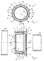
- reducer 1 is a one-piece plastic injection molded part, which is essentially formed by an outer pipe section 2, an inner pipe section 3 and a connecting web 4 connecting these pipe sections 2 and 3.
- the reducer is used in particular for connecting sewer pipes in the building interior.
- the outer pipe section 2 has a substantially cylindrical wall 5 Fig. 3 ), protrude from the twelve projections to the outside. These projections are in the form of narrow, parallel to an axis 6 (FIG. Fig. 3 ) of the outer tube section 2 extending webs and are hereinafter referred to as axial webs 7a to 7l.
- annular groove 9 is inserted into the outer tube section 2, which serves to receive a (not shown) annular seal.
- a radially outwardly projecting collar 11 is molded onto the outer tube section 2, which serves as a stop for the first tube R1 and thus limits the insertion depth of the outer tube section 2 in the first tube R1.
- the inner pipe section 3 is likewise essentially formed by an approximately cylindrical wall 12. At its end 8 facing the end 13 (FIG. Fig. 4 ), the inner pipe section 3 is provided with a radially inwardly projecting collar 14, which serves as a stop for a second pipe R2 (FIG. Fig. 4 ) with a comparatively small diameter. At an axially opposite end 15, an annular groove 16 is inserted into the inner pipe section 3, which in turn serves to receive an annular seal (not shown).
- the connecting web 4 has substantially the shape of a radially aligned to the axis 6 disc, the outside integrally into the pipe section 2, and on the inside merges into the pipe section 3, and thus a fluid-tight, in particular waterproof barrier in the between the pipe sections 2 and 3 formed gap 17 ( Fig. 3 ).
- the intended installation of the reducer 1 is off Fig. 4 seen.
- the reducer 1 with the outer pipe section 2 is in a press fit in the tube R1, wherein the axial webs 7a to 7l radially act on the inner wall of the tube R1.
- the tube R2 is in turn in a press fit in the inner tube section 3, wherein the wall 12, the outside of the Tube R2 radially acted upon.
- the reducer 1 is fitted prior to assembly with seals that einine in the corresponding annular grooves 9 and 16. In the assembled state, an outwardly fluid-tight connection between the tube R1 and the tube R2 is created via the reducer 1.
- the axial webs 7a to 7l are arranged in the insertion direction 18 of the annular groove 9 and the gasket optionally inserted therein, so that the axial webs 7a to 7l in the assembled state of the reducer 1 are not intended to be surrounded by the fluid flowing in the pipes R1 and R2.
- this slip-resistant contour 20 is formed in each case by a multiplicity of axially aligned saw teeth 21, the oblique surface 22 of which faces forward in the insertion direction 18, while the steep surface 23 of each saw tooth 21 points to the rear in the insertion direction 18.
- the saw teeth 21 are thus aligned so that they oppose the insertion of the reducer 1 in the tube R1 no significant resistance, but lock against the pushing out of the reducer 1 from the tube R1.
- the saw teeth 21 are dimensioned such that their steep surface 23 is aligned approximately radially, while the inclined surface 22 is employed relative to the radial at an angle ⁇ of about 60 °.
- the outside of at least the contoured axial webs 7a, 7c, 7e, 7g, 7i and 7k is slightly convex, so that the envelope of the teeth 24 connecting the tips of the teeth 24th ( Fig. 5 ) is slightly curved at least in a front portion. From the Fig. 2 and 6 is further seen that the tooth height of the saw teeth 21 decreases towards the end 10 down to zero. The saw teeth 21 thus run continuously in the vicinity of the collar 11.
- the pipe sections 2 and 3 are arranged coaxially with each other. In alternative embodiments of the reducer according to the invention, deviating from this, it is provided to position the inner pipe section 3 eccentrically to the outer pipe section 2.
- each axial web 7a to 7l is contoured on the outside.
- only the axial webs 7c, 7e, 7i and 7k are provided with the slip-resistant contour 20, while the remaining axial webs 7a, 7b, 7d, 7f, 7g, 7h, 7j and 7l are smooth on the outside.
- the inner wall of the inner pipe section 3 may be wholly or partially provided with a slip-resistant contour to complicate slipping out of the second tube R2 from this pipe section.
Landscapes
- Engineering & Computer Science (AREA)
- General Engineering & Computer Science (AREA)
- Mechanical Engineering (AREA)
- Joints With Sleeves (AREA)
- Rigid Pipes And Flexible Pipes (AREA)
Claims (8)
- Raccord réducteur (1) comprenant- un tronçon tubulaire extérieur (2) à enfiler dans un premier tube (R1),- un tronçon tubulaire intérieur (3) agencé dans le tronçon tubulaire extérieur (2) et destiné à recevoir un second tube (R2) avec un diamètre plus petit par comparaison au premier tube (R1), et- une barrette de liaison (4), qui relie d'une seule pièce le tronçon tubulaire extérieur (2) avec le tronçon tubulaire intérieur (3) et comble ici de façon étanche aux fluides l'intervalle (17) formé entre les tronçons tubulaires (2, 3),dans lequel au moins une saillie (7a-71) qui présente un contour (20) freinant le glissement est conformée à la périphérie extérieure du tronçon tubulaire extérieur (2),
caractérisé en ce que
la ou chaque saillie est formée par une barrette allongée (7a-71) s'étendant au moins sensiblement en direction axiale, dont la face extérieure est dotée du contour (20) freinant le glissement. - Raccord réducteur (1) selon la revendication 1,
caractérisé en ce que la face extérieure de la barrette ou de chaque barrette (7a-71) est légèrement bombée de manière convexe le long de l'extension longitudinale de la barrette (7a-71). - Raccord réducteur (1) selon la revendication 1 ou 2,
caractérisé en ce que le contour (20) freinant le glissement est réalisé à la manière de dents de scie. - Raccord réducteur (1) selon la revendication 3,
caractérisé en ce que le contour (20) freinant le glissement comprend plusieurs dents de scie (21) en rangée les unes contre les autres sensiblement en direction axiale. - Raccord réducteur (1) selon la revendication 4,
caractérisé en ce que la hauteur des dents de scie (21) en rangée les unes contre les autres diminue en direction d'une extrémité (10), postérieure dans la direction d'enfilage (18) du tronçon tubulaire extérieur (2), de ce tronçon tubulaire (2). - Raccord réducteur (1) selon l'une des revendications 1 à 5,
caractérisé en ce que, à une extrémité (10), postérieure dans la direction d'enfilage (18) du tronçon tubulaire extérieur (2), de ce tronçon tubulaire (2) est agencée une collerette (11) dépassant radialement vers l'extérieur, qui limite la profondeur d'enfilage du tronçon tubulaire extérieur (2). - Raccord réducteur (1) selon l'une des revendications 1 à 6,
caractérisé en ce qu'il est prévu sur le tronçon tubulaire extérieur (2) un joint annulaire pour étancher entre le tronçon tubulaire extérieur (2) et la paroi intérieure du premier tube (R1) enfilé sur celui-ci, ou au moins une gorge annulaire (9) destinée à recevoir un tel joint, dans lequel la ou chaque saillie (7a-71) dotée du contour (20) freinant le glissement est/sont agencée(s) en direction d'enfilage (18) derrière le joint ou la gorge annulaire (9). - Raccord réducteur (1) selon l'une des revendications 1 à 7,
caractérisé en ce qu'il est réalisé sous la forme d'une pièce en matière plastique injectée d'un seul tenant.
Applications Claiming Priority (1)
| Application Number | Priority Date | Filing Date | Title |
|---|---|---|---|
| DE200920014575 DE202009014575U1 (de) | 2009-10-28 | 2009-10-28 | Reduzierstück |
Publications (2)
| Publication Number | Publication Date |
|---|---|
| EP2317201A1 EP2317201A1 (fr) | 2011-05-04 |
| EP2317201B1 true EP2317201B1 (fr) | 2012-07-18 |
Family
ID=43528360
Family Applications (1)
| Application Number | Title | Priority Date | Filing Date |
|---|---|---|---|
| EP20100012550 Active EP2317201B1 (fr) | 2009-10-28 | 2010-09-30 | Raccord de réduction |
Country Status (2)
| Country | Link |
|---|---|
| EP (1) | EP2317201B1 (fr) |
| DE (1) | DE202009014575U1 (fr) |
Families Citing this family (1)
| Publication number | Priority date | Publication date | Assignee | Title |
|---|---|---|---|---|
| FR3052225B1 (fr) * | 2016-06-06 | 2018-11-16 | Frederic Garate | Piece de raccord, pour le raccordement d'une conduite de descente de gouttiere a une conduite d'evacuation et procede de raccordement correspondant |
Family Cites Families (5)
| Publication number | Priority date | Publication date | Assignee | Title |
|---|---|---|---|---|
| US3913928A (en) * | 1973-05-09 | 1975-10-21 | Seiichi Yamaguchi | Resilient joint |
| DE8409721U1 (de) * | 1984-03-29 | 1984-06-20 | Braukmann, Bernhard W., 6950 Mosbach | Als steckverbindung ausgebildete kupplung |
| NL8801130A (nl) * | 1988-04-29 | 1989-11-16 | Wavin Bv | Afdichtingsmanchet voor toepassing bij buisverbinding, mof voorzien van afdichtingsmanchet en buizenstelsel dat een dergelijke mof omvat. |
| DE20315084U1 (de) | 2003-09-30 | 2003-12-18 | Zimmermann, Josef | Kunststoffformteil zum Reduzieren von Rohrdurchmessern mit diagonal verlaufendem Verbindungssteg |
| US20100007132A1 (en) * | 2006-10-06 | 2010-01-14 | Halcor Metal Works S.A. | Insert for connecting standardized fittings with multilayer pipes |
-
2009
- 2009-10-28 DE DE200920014575 patent/DE202009014575U1/de not_active Expired - Lifetime
-
2010
- 2010-09-30 EP EP20100012550 patent/EP2317201B1/fr active Active
Also Published As
| Publication number | Publication date |
|---|---|
| EP2317201A1 (fr) | 2011-05-04 |
| DE202009014575U1 (de) | 2011-03-10 |
Similar Documents
| Publication | Publication Date | Title |
|---|---|---|
| EP1593898B1 (fr) | Elément d'étanchéité | |
| DE102007008066B4 (de) | Fitting | |
| EP2108874B1 (fr) | Pièce de raccordement | |
| EP3428498B1 (fr) | Tube, en particulier tube en plastique pour conduites d'évacuation d'eaux usées | |
| DE20310390U1 (de) | Anschlussdichtung mit Ratschenzähnen | |
| EP2724065B1 (fr) | Raccord de tuyau flexible et système de tuyau flexible correspondant | |
| DE202006020632U1 (de) | Anschlussstück | |
| EP3198179B1 (fr) | Système de liaison pour un tube ondulé | |
| EP3036469A1 (fr) | Élément d'insertion, procédé de raccordement entre un élément d'insertion, un élément tubulaire et un élément douille, et élément d'insertion permettant l'insertion d'une extrémité de tube | |
| EP0327080A1 (fr) | Raccord pour tuyau | |
| EP2317201B1 (fr) | Raccord de réduction | |
| EP2366934B1 (fr) | Pièce de raccordement pour tuyaux métalliques | |
| DE102010016972A1 (de) | Anschlussverbindung für ein Rohr | |
| DE202011004259U1 (de) | Schlauchkupplung | |
| EP1591712B1 (fr) | Tuyau de connection et sa application | |
| EP3985296B1 (fr) | Système de raccordement | |
| DE60205587T2 (de) | Dichtung für den Zusammenbau von rohrförmigen Elementen von Fluidkreisläufen | |
| DE19905809A1 (de) | Anschlußverbindung und Anschlußelement für ringgewellte Schlauchleitungen | |
| DE4303827C2 (de) | Bohr-Dichtungsring | |
| EP2213500A1 (fr) | Conduite de carburant et procédé de fabrication d'une conduite de carburant | |
| DE1949746C3 (de) | Dichtung von Rohrverbindungsstellen | |
| DE202012006001U1 (de) | Rohrverbindungsstück zum stirnseitigen Verbinden zweier Rohre | |
| EP2369212B1 (fr) | Dispositif de raccordement | |
| EP2667074B1 (fr) | Système de connexion de tuyaux avec clip de serrage | |
| DE3509231A1 (de) | Schlauch- bzw. rohranschluss |
Legal Events
| Date | Code | Title | Description |
|---|---|---|---|
| PUAI | Public reference made under article 153(3) epc to a published international application that has entered the european phase |
Free format text: ORIGINAL CODE: 0009012 |
|
| AK | Designated contracting states |
Kind code of ref document: A1 Designated state(s): AL AT BE BG CH CY CZ DE DK EE ES FI FR GB GR HR HU IE IS IT LI LT LU LV MC MK MT NL NO PL PT RO SE SI SK SM TR |
|
| AX | Request for extension of the european patent |
Extension state: BA ME RS |
|
| 17P | Request for examination filed |
Effective date: 20111104 |
|
| GRAP | Despatch of communication of intention to grant a patent |
Free format text: ORIGINAL CODE: EPIDOSNIGR1 |
|
| GRAC | Information related to communication of intention to grant a patent modified |
Free format text: ORIGINAL CODE: EPIDOSCIGR1 |
|
| GRAS | Grant fee paid |
Free format text: ORIGINAL CODE: EPIDOSNIGR3 |
|
| GRAA | (expected) grant |
Free format text: ORIGINAL CODE: 0009210 |
|
| AK | Designated contracting states |
Kind code of ref document: B1 Designated state(s): AL AT BE BG CH CY CZ DE DK EE ES FI FR GB GR HR HU IE IS IT LI LT LU LV MC MK MT NL NO PL PT RO SE SI SK SM TR |
|
| REG | Reference to a national code |
Ref country code: GB Ref legal event code: FG4D Free format text: NOT ENGLISH |
|
| REG | Reference to a national code |
Ref country code: CH Ref legal event code: NV Representative=s name: E. BLUM & CO. AG PATENT- UND MARKENANWAELTE VSP Ref country code: CH Ref legal event code: EP |
|
| REG | Reference to a national code |
Ref country code: AT Ref legal event code: REF Ref document number: 567121 Country of ref document: AT Kind code of ref document: T Effective date: 20120815 Ref country code: IE Ref legal event code: FG4D Free format text: LANGUAGE OF EP DOCUMENT: GERMAN |
|
| REG | Reference to a national code |
Ref country code: DE Ref legal event code: R096 Ref document number: 502010001031 Country of ref document: DE Effective date: 20120913 |
|
| REG | Reference to a national code |
Ref country code: NL Ref legal event code: VDEP Effective date: 20120718 |
|
| REG | Reference to a national code |
Ref country code: LT Ref legal event code: MG4D Effective date: 20120718 |
|
| PG25 | Lapsed in a contracting state [announced via postgrant information from national office to epo] |
Ref country code: CY Free format text: LAPSE BECAUSE OF FAILURE TO SUBMIT A TRANSLATION OF THE DESCRIPTION OR TO PAY THE FEE WITHIN THE PRESCRIBED TIME-LIMIT Effective date: 20120718 Ref country code: LT Free format text: LAPSE BECAUSE OF FAILURE TO SUBMIT A TRANSLATION OF THE DESCRIPTION OR TO PAY THE FEE WITHIN THE PRESCRIBED TIME-LIMIT Effective date: 20120718 Ref country code: IS Free format text: LAPSE BECAUSE OF FAILURE TO SUBMIT A TRANSLATION OF THE DESCRIPTION OR TO PAY THE FEE WITHIN THE PRESCRIBED TIME-LIMIT Effective date: 20121118 Ref country code: HR Free format text: LAPSE BECAUSE OF FAILURE TO SUBMIT A TRANSLATION OF THE DESCRIPTION OR TO PAY THE FEE WITHIN THE PRESCRIBED TIME-LIMIT Effective date: 20120718 Ref country code: NO Free format text: LAPSE BECAUSE OF FAILURE TO SUBMIT A TRANSLATION OF THE DESCRIPTION OR TO PAY THE FEE WITHIN THE PRESCRIBED TIME-LIMIT Effective date: 20121018 Ref country code: FI Free format text: LAPSE BECAUSE OF FAILURE TO SUBMIT A TRANSLATION OF THE DESCRIPTION OR TO PAY THE FEE WITHIN THE PRESCRIBED TIME-LIMIT Effective date: 20120718 |
|
| PG25 | Lapsed in a contracting state [announced via postgrant information from national office to epo] |
Ref country code: PT Free format text: LAPSE BECAUSE OF FAILURE TO SUBMIT A TRANSLATION OF THE DESCRIPTION OR TO PAY THE FEE WITHIN THE PRESCRIBED TIME-LIMIT Effective date: 20121119 Ref country code: SE Free format text: LAPSE BECAUSE OF FAILURE TO SUBMIT A TRANSLATION OF THE DESCRIPTION OR TO PAY THE FEE WITHIN THE PRESCRIBED TIME-LIMIT Effective date: 20120718 Ref country code: GR Free format text: LAPSE BECAUSE OF FAILURE TO SUBMIT A TRANSLATION OF THE DESCRIPTION OR TO PAY THE FEE WITHIN THE PRESCRIBED TIME-LIMIT Effective date: 20121019 Ref country code: LV Free format text: LAPSE BECAUSE OF FAILURE TO SUBMIT A TRANSLATION OF THE DESCRIPTION OR TO PAY THE FEE WITHIN THE PRESCRIBED TIME-LIMIT Effective date: 20120718 Ref country code: SI Free format text: LAPSE BECAUSE OF FAILURE TO SUBMIT A TRANSLATION OF THE DESCRIPTION OR TO PAY THE FEE WITHIN THE PRESCRIBED TIME-LIMIT Effective date: 20120718 Ref country code: PL Free format text: LAPSE BECAUSE OF FAILURE TO SUBMIT A TRANSLATION OF THE DESCRIPTION OR TO PAY THE FEE WITHIN THE PRESCRIBED TIME-LIMIT Effective date: 20120718 |
|
| PG25 | Lapsed in a contracting state [announced via postgrant information from national office to epo] |
Ref country code: NL Free format text: LAPSE BECAUSE OF FAILURE TO SUBMIT A TRANSLATION OF THE DESCRIPTION OR TO PAY THE FEE WITHIN THE PRESCRIBED TIME-LIMIT Effective date: 20120718 |
|
| BERE | Be: lapsed |
Owner name: HAAS, THOMAS Effective date: 20120930 |
|
| PG25 | Lapsed in a contracting state [announced via postgrant information from national office to epo] |
Ref country code: EE Free format text: LAPSE BECAUSE OF FAILURE TO SUBMIT A TRANSLATION OF THE DESCRIPTION OR TO PAY THE FEE WITHIN THE PRESCRIBED TIME-LIMIT Effective date: 20120718 Ref country code: MC Free format text: LAPSE BECAUSE OF NON-PAYMENT OF DUE FEES Effective date: 20120930 Ref country code: DK Free format text: LAPSE BECAUSE OF FAILURE TO SUBMIT A TRANSLATION OF THE DESCRIPTION OR TO PAY THE FEE WITHIN THE PRESCRIBED TIME-LIMIT Effective date: 20120718 Ref country code: ES Free format text: LAPSE BECAUSE OF FAILURE TO SUBMIT A TRANSLATION OF THE DESCRIPTION OR TO PAY THE FEE WITHIN THE PRESCRIBED TIME-LIMIT Effective date: 20121029 Ref country code: RO Free format text: LAPSE BECAUSE OF FAILURE TO SUBMIT A TRANSLATION OF THE DESCRIPTION OR TO PAY THE FEE WITHIN THE PRESCRIBED TIME-LIMIT Effective date: 20120718 |
|
| PLBE | No opposition filed within time limit |
Free format text: ORIGINAL CODE: 0009261 |
|
| STAA | Information on the status of an ep patent application or granted ep patent |
Free format text: STATUS: NO OPPOSITION FILED WITHIN TIME LIMIT |
|
| PG25 | Lapsed in a contracting state [announced via postgrant information from national office to epo] |
Ref country code: IT Free format text: LAPSE BECAUSE OF FAILURE TO SUBMIT A TRANSLATION OF THE DESCRIPTION OR TO PAY THE FEE WITHIN THE PRESCRIBED TIME-LIMIT Effective date: 20120718 Ref country code: SK Free format text: LAPSE BECAUSE OF FAILURE TO SUBMIT A TRANSLATION OF THE DESCRIPTION OR TO PAY THE FEE WITHIN THE PRESCRIBED TIME-LIMIT Effective date: 20120718 |
|
| 26N | No opposition filed |
Effective date: 20130419 |
|
| REG | Reference to a national code |
Ref country code: IE Ref legal event code: MM4A |
|
| REG | Reference to a national code |
Ref country code: HU Ref legal event code: AG4A Ref document number: E015948 Country of ref document: HU |
|
| PG25 | Lapsed in a contracting state [announced via postgrant information from national office to epo] |
Ref country code: BE Free format text: LAPSE BECAUSE OF NON-PAYMENT OF DUE FEES Effective date: 20120930 Ref country code: BG Free format text: LAPSE BECAUSE OF FAILURE TO SUBMIT A TRANSLATION OF THE DESCRIPTION OR TO PAY THE FEE WITHIN THE PRESCRIBED TIME-LIMIT Effective date: 20121018 Ref country code: IE Free format text: LAPSE BECAUSE OF NON-PAYMENT OF DUE FEES Effective date: 20120930 |
|
| REG | Reference to a national code |
Ref country code: DE Ref legal event code: R097 Ref document number: 502010001031 Country of ref document: DE Effective date: 20130419 |
|
| PGFP | Annual fee paid to national office [announced via postgrant information from national office to epo] |
Ref country code: HU Payment date: 20130924 Year of fee payment: 4 |
|
| PG25 | Lapsed in a contracting state [announced via postgrant information from national office to epo] |
Ref country code: MT Free format text: LAPSE BECAUSE OF FAILURE TO SUBMIT A TRANSLATION OF THE DESCRIPTION OR TO PAY THE FEE WITHIN THE PRESCRIBED TIME-LIMIT Effective date: 20120718 Ref country code: AL Free format text: LAPSE BECAUSE OF FAILURE TO SUBMIT A TRANSLATION OF THE DESCRIPTION OR TO PAY THE FEE WITHIN THE PRESCRIBED TIME-LIMIT Effective date: 20120718 |
|
| PGFP | Annual fee paid to national office [announced via postgrant information from national office to epo] |
Ref country code: FR Payment date: 20130918 Year of fee payment: 4 |
|
| PG25 | Lapsed in a contracting state [announced via postgrant information from national office to epo] |
Ref country code: TR Free format text: LAPSE BECAUSE OF FAILURE TO SUBMIT A TRANSLATION OF THE DESCRIPTION OR TO PAY THE FEE WITHIN THE PRESCRIBED TIME-LIMIT Effective date: 20120718 |
|
| PG25 | Lapsed in a contracting state [announced via postgrant information from national office to epo] |
Ref country code: LU Free format text: LAPSE BECAUSE OF NON-PAYMENT OF DUE FEES Effective date: 20120930 Ref country code: SM Free format text: LAPSE BECAUSE OF FAILURE TO SUBMIT A TRANSLATION OF THE DESCRIPTION OR TO PAY THE FEE WITHIN THE PRESCRIBED TIME-LIMIT Effective date: 20120718 |
|
| GBPC | Gb: european patent ceased through non-payment of renewal fee |
Effective date: 20140930 |
|
| REG | Reference to a national code |
Ref country code: FR Ref legal event code: ST Effective date: 20150529 |
|
| PG25 | Lapsed in a contracting state [announced via postgrant information from national office to epo] |
Ref country code: GB Free format text: LAPSE BECAUSE OF NON-PAYMENT OF DUE FEES Effective date: 20140930 Ref country code: MK Free format text: LAPSE BECAUSE OF FAILURE TO SUBMIT A TRANSLATION OF THE DESCRIPTION OR TO PAY THE FEE WITHIN THE PRESCRIBED TIME-LIMIT Effective date: 20120718 |
|
| PG25 | Lapsed in a contracting state [announced via postgrant information from national office to epo] |
Ref country code: HU Free format text: LAPSE BECAUSE OF NON-PAYMENT OF DUE FEES Effective date: 20141001 Ref country code: FR Free format text: LAPSE BECAUSE OF NON-PAYMENT OF DUE FEES Effective date: 20140930 |
|
| PGFP | Annual fee paid to national office [announced via postgrant information from national office to epo] |
Ref country code: CH Payment date: 20150922 Year of fee payment: 6 |
|
| REG | Reference to a national code |
Ref country code: CH Ref legal event code: PL |
|
| PG25 | Lapsed in a contracting state [announced via postgrant information from national office to epo] |
Ref country code: LI Free format text: LAPSE BECAUSE OF NON-PAYMENT OF DUE FEES Effective date: 20160930 Ref country code: CH Free format text: LAPSE BECAUSE OF NON-PAYMENT OF DUE FEES Effective date: 20160930 |
|
| REG | Reference to a national code |
Ref country code: DE Ref legal event code: R082 Ref document number: 502010001031 Country of ref document: DE Representative=s name: FDST PATENTANWAELTE FREIER DOERR STAMMLER TSCH, DE Ref country code: DE Ref legal event code: R081 Ref document number: 502010001031 Country of ref document: DE Owner name: HAAS, ANGELA, DE Free format text: FORMER OWNER: HAAS, THOMAS, 91074 HERZOGENAURACH, DE |
|
| REG | Reference to a national code |
Ref country code: AT Ref legal event code: PC Ref document number: 567121 Country of ref document: AT Kind code of ref document: T Owner name: ANGELA HAAS, DE Effective date: 20200928 |
|
| PGFP | Annual fee paid to national office [announced via postgrant information from national office to epo] |
Ref country code: CZ Payment date: 20230921 Year of fee payment: 14 Ref country code: AT Payment date: 20230915 Year of fee payment: 14 |
|
| PGFP | Annual fee paid to national office [announced via postgrant information from national office to epo] |
Ref country code: DE Payment date: 20231027 Year of fee payment: 14 |