EP2317008B1 - Verfahren und Vorrichtung zum Öffnen eines Nips - Google Patents
Verfahren und Vorrichtung zum Öffnen eines Nips Download PDFInfo
- Publication number
- EP2317008B1 EP2317008B1 EP20100176729 EP10176729A EP2317008B1 EP 2317008 B1 EP2317008 B1 EP 2317008B1 EP 20100176729 EP20100176729 EP 20100176729 EP 10176729 A EP10176729 A EP 10176729A EP 2317008 B1 EP2317008 B1 EP 2317008B1
- Authority
- EP
- European Patent Office
- Prior art keywords
- roll
- belt
- severing
- guide
- nip
- Prior art date
- Legal status (The legal status is an assumption and is not a legal conclusion. Google has not performed a legal analysis and makes no representation as to the accuracy of the status listed.)
- Not-in-force
Links
Images


Classifications
-
- D—TEXTILES; PAPER
- D21—PAPER-MAKING; PRODUCTION OF CELLULOSE
- D21G—CALENDERS; ACCESSORIES FOR PAPER-MAKING MACHINES
- D21G1/00—Calenders; Smoothing apparatus
- D21G1/002—Opening or closing mechanisms; Regulating the pressure
-
- D—TEXTILES; PAPER
- D21—PAPER-MAKING; PRODUCTION OF CELLULOSE
- D21F—PAPER-MAKING MACHINES; METHODS OF PRODUCING PAPER THEREON
- D21F3/00—Press section of machines for making continuous webs of paper
- D21F3/02—Wet presses
-
- D—TEXTILES; PAPER
- D21—PAPER-MAKING; PRODUCTION OF CELLULOSE
- D21F—PAPER-MAKING MACHINES; METHODS OF PRODUCING PAPER THEREON
- D21F7/00—Other details of machines for making continuous webs of paper
- D21F7/04—Paper-break control devices
-
- D—TEXTILES; PAPER
- D21—PAPER-MAKING; PRODUCTION OF CELLULOSE
- D21G—CALENDERS; ACCESSORIES FOR PAPER-MAKING MACHINES
- D21G5/00—Safety devices
- D21G5/005—Safety devices for calenders
Definitions
- the invention relates to a method for opening a nip treated a fibrous web, which is formed by a circulating over at least two guide rollers belt with a counter roll by the belt over a wrap angle greater than 5 ° conforms to the peripheral surface of the backing roll, wherein the fibrous web by means is monitored by a sensor in front of the nip for tearing or folding and in the event of cracks or creases, the sensor via a control device, a signal to a separation device passes, which moves at least one guide roller during the separation process motor within 0.9 seconds.
- the invention further relates to a device for opening a nip serving for the treatment of a fibrous web, which is formed by a band circulating over at least two guide rollers with a counter-roller by the band conforming to the peripheral surface of the counter-roller over a wrap angle greater than 5 ° the at least one guide roller is displaceably mounted via a separating device, wherein a control is provided which activates the separating device on the basis of a detected via a sensor error of the current fibrous web.
- Nips are the contact surfaces between two circumferential treatment surfaces, between which a fibrous web can be treated.
- calender nipples are used to explain the invention, between which a paper or board web is calendered.
- one of the contact surfaces is provided with a relatively soft surface, and the other treatment surface is formed by a hard, very smooth and often also heatable treatment surface.
- Nips can have very different lengths in the web running direction. This depends, for example, on the type of calender and the pressure under which the treatment surfaces are pressed on one another.
- one of the treatment surfaces is provided with a softer plastic layer, care must be taken that there is never a second heated treatment surface with it direct contact comes, but always a paper web is present in between, which transported away the heat dissipated. In the case of a web break, for example, care must be taken to ensure that the treatment areas separate quickly from each other.
- the first known publication, the EP 1176252 81 refers to a roll calender, which generally has relatively short nip lengths.
- a lower roller which forms a nip with at least one further roller, can be lowered rapidly via a hydraulic cylinder in the event of a fault.
- the lowering operation is skilfully decelerated in order to avoid an abrupt placement of the roller and an associated vibration.
- Such a hydraulic cylinder is activated when, for example, a photocell detects a crack in a fibrous web.
- Modern calenders with very long nips are the band calenders. These are the paper or board web by means of a circulating belt over a larger angle of wrap to a heated Counter roll pressed. In this case, the band is held under belt tension, so that results from the resultant of the curvature and a system pressure to the web. If the band is made of plastic, there is also the danger of overheating of the band in case of web break. On the other hand, if the band is made of metal, that is usually made of a thin sheet steel, its danger of being damaged in the event of folds in the web is very great. The web is retracted in such a calender with rotating counter roll and with applied and circulating belt, which further increases the risk of belt damage.
- the object is achieved in the method by the separation device, the at least one guide roll while maintaining a Bandzugschreib offset such that the tape is spaced after the separation process of the backing roll, wherein the tape is tensioned during or immediately after the separation process via a clamping element.
- the term "motor” is to be understood here as the involvement of all possible drives which can move a roller by electrical, hydraulic or pneumatic means, with rotary motion or stroke. Possibly. are also several such drives necessary.
- the period of 0.9 seconds is an acceptable size at today's web speeds of about 1000 to 2000 m / min, where on the one hand the known in the art sensor for detecting cracks or wrinkles in the web still arranged in a suitable area in front of the calender on the other hand, enough time remains for the control and the motorized separator to separate the calender nip before the Defile in the web reaches him.
- the band wraps around the counter roll at least 5 ° on the outer circumference, so that a resultant force from the belt tension can produce a sufficiently large contact pressure.
- the clamping element holds the strip tension at least almost constant during the separation process.
- the band tension loss caused by the separation from the counter roll and the reduction of the loop around the counter roll is compensated in this case by the clamping element.
- the counter roll By the opening process of the nip according to the invention, it is possible and cheap, the counter roll to a surface temperature of more than 130 ° C, especially when using tapes with a Plastic part, to heat. This produces a higher web quality after calendering.
- the separation device moves a guide roller on a circular path away from the counter roll.
- the guide roller may be mounted in a pivotable lever, so that significantly less friction losses occur during the separation process as in a linear guide Leitvvalzenlagers.
- the object underlying the invention is achieved in that a clamping element is provided which can be acted on during a separating operation with a force for tensioning the strip.
- the clamping element comprises a roller.
- the roller which acts against the belt to build up the tension, rotates at the same peripheral speed as the belt speed. As a result, a contact friction and thus wear is avoided.
- the counter-roller is fixedly mounted.
- the counter roll which is often heatable, is the largest and heaviest roll in a belt calender. Moving them to separate the nip is obvious but energetically obsolete. If the Roll axis of the mating roll remains fixed, their supply can be hard-piped with a Helz medium, so that hardly any sealing problems occur as in hose connections.
- the separation device comprises a servomotor.
- a motor With such a motor, the movement of the guide roller can be controlled specifically.
- Under a motor are electrical, hydraulic and pneumatic actuators to understand. If, for example, a simple hydraulic cylinder is selected as the engine, braked motion controls of the piston can be realized, as described in US Pat EP 1176252 B1 are disclosed.
- the at least one guide roller mounted in a lever is pivotable about an axis of rotation.
- the axis of rotation is the axis of a second guide roller. It saves the storage of a separate axis of rotation and uses an existing axis, namely a belt guide, as a rotation axis. This saves space and material.
- a controller which controls the disconnecting device on the basis of an error detected by a sensor active fibrous web activated. It is therefore ensured that the separation of the nip takes place automatically.
- the belt calender 1 in FIG. 1 consists essentially of a three circulating rollers 11, 12, 13 circumferential band 4, which has a Umschtingungswinkel> 5 ° contact with a counter-roller 5.
- the belt is driven, for example, in unillustrated form over one of the three guide rollers 11 12, 13 until it has reached the Umangsgeschwingkeit counter roller 5 and the fibrous web 2. In practice, such a band can be up to 10 m wide.
- the fibrous web 2 passes through the nip 3 between the belt 4 and counter-roller 5.
- the nip 3 is thus a contact zone between the belt 4 and counter-roller 5, which may be between 100 and 1000 mm in the web running direction, depending on the type of fiber web.
- the counter-roller 5 is heated in an unillustrated form to above 130 ° C surface temperature and stored permanently.
- suitable heat transfer fluids that are passed through the interior of the roll, or external heaters that operate inductively, capacitively or by Helßluftanblasung.
- a created by an additional roller 18 Saknip 19 has been created on the counter-roller 5, which is not directly related to the invention, but the calender gives a greater calendering potential.
- All band guide rollers 11, 12, 13 are mounted on a common frame 20, which in turn is housed in a housing 17.
- the diameter of these guide rolls is in the range of 400 to 1000 mm.
- the band 4 undergoes a Bandzugspsnnung.
- Both guide roller 11 and guide roller 12 have a distance to the counter roll 5, which is greater than the sum of strip and web thickness.
- To the frame 20 engages a servomotor 9, which can rotate the guide rollers 11 and 13 about an axis of rotation 16 which corresponds to the axis of the guide roller 12 at the same time.
- the lever 15 so is responsible for the fact that the guide roller 11 can move away on a circular arc of the counter-roller 5. As a result, the belt 4 also lifts off the counter-roller 5.
- This movement is initiated by a sensor 6 when it detects a fault in the web 2. Such errors are, for example, cracks or wrinkles.
- the signal (dashed line) is forwarded to a controller 7, which in turn causes the servomotor 9 to move.
- the guide roller 11 is pivoted away from the counter-roller 5, that the tape 4 no later than 0.9 seconds after detection of the defect in the web 2 has no contact with the counter-roller 5.
- a special advantage is provided by a tensioning element 10. This serves to adjust the lost arc of the band 4 about the counter-roller 5 so that the band retains a band tensile stress.
- the tensioning element consists essentially of a pressure transducer 21 and a roller 14 which presses against the inner surface of the belt.
- the roller 14 is identical to the guide roller 11.
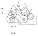
- FIG. 2 alternatively shows a separate roller 14, over a Pressure transducer 21 and a lever system 22 can be pressed against the belt to build a tensile band tension during or shortly after the separation process.
- the pressure transducer 21 is a hydraulic cylinder in both examples.
- the hydraulic cylinder is controlled position-controlled and / or druckgeregeit.
- a cushioning not shown, is provided.
- spindles are suitable for the tension. Linear drives, pneumatic cylinders, tension over weight load or the like.
- FIG. 3 To further illustrate the invention is in FIG. 3 the calender 1 is shown once with the nip 3 open. Clearly it can be seen that the band 4 no longer touches the counter-roller, but is still stretched by means of the clamping element 10.
- the band 4 is preferably made of plastic, for example PU, PEEK, PFD, Teflon, rubber and mixtures with fibers of glass, aramid or metal fabric.
- the band can also be made of plastic with a thin metal underlayer. Other materials for the band are metal or metal with a plastic underlayer.
- the band is additionally heated.
- the guide rollers can be heated or the belt are heated inductively.
- the tape has a surface roughness of ⁇ 1.0 microns, better less than 0.5 microns.
- the tape has a thickness of 0.5 to 10 mm, preferably 0.8 to 5 mm,
- the band 4 does not have to provide a calendering effect, but can also be used only for effective heating of the web 2 on the heated counter-roller 5 before the web passes the additional nip 19 for elgentliche Glanz- and Glättssteig für für a calender 1
- a calender 1 which has a preheating section for the web 2 under the band 4 or possibly also a Nachfiltier behind the nip with a similar band structure, the band 4 is pressed at a pressure of 0.1 to 1 MPa against the backing roll 5 to the temperature the counter roller 5 to penetrate deep into the paper or the cardboard and so to improve the smoothing result.
- a strip treatment zone is created immediately before or after a supplementary nip 19.
- the advantage of this method of smoothing or of this arrangement lies in the fact that a water- and intestinal-opaque band is used, so that the moisture can not escape from the web 2 in the band treatment zone. The moisture is indeed driven to the cold side of the tape, but remains there stored. Only after the strip treatment zone moisture can escape from the paper web into the environment.
- the illustrated calender 1 can also be combined in a variety of ways with a Mehrwalzenkander or another calender.
Landscapes
- Paper (AREA)
- Rolls And Other Rotary Bodies (AREA)
- Treatment Of Fiber Materials (AREA)
Description
- Die Erfindung betrifft ein Verfahren zum Öffnen eines eine Faserstoffbahn behandelnden Nips, der durch ein über wenigstens zwei Leitwalzen umlaufendes Band mit einer Gegenwalze gebildet wird, indem sich das Band über einen Umschlingungswinkel größer als 5° an die Umfangsfläche der Gegenwalze anschmiegt, wobei die Faserstoffbahn mittels eines Sensors vor dem Nip auf Reißen oder Faltungen überwacht wird und im Falle des Auftretens von Rissen oder Faltungen der Sensor über eine Steuerungsvorrichtung ein Signal an eine Trennvorrichtung weitergibt, die wenigstens eine Leitwalze während des Trennvorgangs motorisch innerhalb von 0,9 Sekunden versetzt.
- Die Erfindung betrifft weiterhin eine Vorrichtung zum Öffnen eines der Behandlung einer Faserstoffbahn dienenden Nips, der durch ein über wenigstens zwei Leitwalzen umlaufendes Band mit einer Gegenwalze gebildet ist, indem sich das Band über einen Umschlingungswinkel größer als 5° an die Umfangsfläche der Gegenwalze anschmiegt, bei der wenigstens eine Leitwalze über eine Trennvorrichtung versetzbar gelagert ist, wobei eine Steuerung vorgesehen ist, die die Trennvorrichtung aufgrund eines über einen Sensor erfassten Fehlers der laufenden Faserstoffbahn aktiviert.
- Ein derartiges Verfahren und eine derartige Vorrichtung sind aus
DE 10 2007 045 902 A1 bekannt. Hier sind verschiedene Möglichkeiten angegeben, um das Band eines Kalanders zu schützen, wenn eine Beschädigung der im Nip behandelten Materialbahn erfasst wird. Neben der Möglichkeit, ein Schutzmaterial auf das Band aufzubringen, wird angegeben, die Spannung des Kalanderbandes zu entlasten, indem eine Leitwalze verfahren wird. Weiterhin kann eine Nipöffnungsvorrichtung vorgesehen sein. Das Band des Bandkalanders ist als Metallband mit einer Dicke von 1 mm ausgebildet. - Nips sind die Kontaktflächen zwischen zwei umlaufenden Behandlungsflächen, zwischen denen eine Faserstoffbahn behandelt werden kann. Im Folgenden werden zur Erläuterung der Erfindung Kalandernips herangezogen, zwischen denen eine Papier- oder Kartonbahn satiniert wird. In der Regel ist eine der Kontaktflächen mit einer relativ weichen Oberfläche ausgestattet, und die andere Behandlungsfläche wird durch eine harte, sehr glatte und oft auch beheizbare Behandlungsfläche gebildet. Nips können in Bahnlaufrichtung sehr unterschiedliche Längen haben. Das hängt beispielsweise von der Art des Kalanders ab und unter welchem Druck die Behandlungsflächen aufeinandergepresst werden. Ist eine der Behandlungsflächen mit einer weicheren Kunststoffschicht versehen, so muss darauf geachtet werden, dass niemals eine zweite beheizte Behandlungsfläche mit ihr in unmittelbaren Kontakt kommt, sondern immer eine Papierbahn dazwischen vorhanden ist, die isolierend die abgegebene Wärme wegtransportiert. Im Falle eines Bahnrisses muss also beispielsweise dafür gesorgt werden, dass sich die Behandlungsflächen schnell voneinander trennen.
- Aber auch bei einer eventuellen Faltenbildung der Bahn ist ein sogenannter Schnellrennvorgang angesagt, weil ansonsten die elastische Oberfläche markiert werden könnte. Derartige Markierungen in der Oberfläche würden sich immer wieder in die Papier- oder Kartonbahn eindrücken und sie so unverkäuflich machen.
- Im Folgenden soll auf den Stand der Technik eingegangen werden. Die erste bekannte Verörfentlichung, die
EP 1176252 81 - Ein solcher Hydraulikzylinder wird dann aktiviert, wenn beispielsweise eine Lichtschranke einen Riss in einer Faserstoffbahn feststellt.
- Für einen Kalander mit einem längeren Nip, einem in der Fachwelt bekannten Schuhkalander, ist ein weiterer Schnelltrennvorgang in der
WO 02/040771 A1 - Moderne Kalander mit sehr langen Nips sind die Bandkalander. Bei diesen wird die Papier- oder Kartonbahn mittels eines umlaufenden Bandes über einen größeren Umschlingungswinkel an eine beheizte Gegenwalze gedrückt. Dabei wird das Band unter Bandzugspannung gehalten, so dass sich aus der Resultierenden der Krümmung auch ein Anlagedruck an die Bahn ergibt. Ist das Band aus Kunststoff ist auch hier die Gefahr einer Überhitzung des Bandes bei Bahnriss gegeben. Ist das Band dagegen aus Metall, also in der Regel aus einem dünnen Stahlblech, so ist dessen Gefahr, bei Falten in der Bahn beschädigt zu werden, sehr groß. Die Bahn wird in einem solchen Kalander mit rotierender Gegenwalze und mit angelegtem und umlaufendem Band eingezogen, was die Gefahr der Bandbeschädigung weiter erhöht.
- Es ist die Aufgabe der Erfindung, eine bandschonende Möglichkeit zum Schnelltrennen eines Nips in einem Bandkalander zu schaffen.
- Die Aufgabe wird bei dem Verfahren gelöst, indem die Trennvorrichtung die wenigstens eine Leitwalze unter Beibehaltung einer Bandzugspannung derart versetzt, dass das Band nach dem Trennvorgang von der Gegenwalze beabstandet ist, wobei das Band während oder unmittelbar nach dem Trennvorgang über ein Spannelement gespannt wird.
- Unter dem Begriff "motorisch" ist hier die Mitwirkung aller möglichen Antriebe zu verstehen, die auf elektrischem, hydraulischem oder pneumatischem Weg, mit Drehbewegung oder Hub, eine Walze bewegen können. Ggf. sind auch mehrere solcher Antriebe notwendig. Der Zeitraum 0,9 Sekunden ist bei den heutigen Bahngeschwindigkeiten von ca. 1000 bis 2000 m/min eine akzeptable Größe, wo einerseits der in der Fachwelt bekannte Sensor zur Detektion von Rissen oder Falten in der Bahn noch in einem geeigneten Bereich vor dem Kalander angeordnet sein kann, andererseits der Steuerung und der motorischen Trennvorrichtung genug Zeit bleibt, den Kalandernip zu trennen, bevor die Fehlstelle in der Bahn ihn erreicht. Das Band umschlingt die Gegenwalze wenigstens um 5° auf dem Außenumfang, damit eine resultierende Kraft aus der Bandspannung einen ausreichend großen Anpressdruck erzeugen kann.
- Würden Band und Gegenwalze beispielsweise - so wie es nahe liegen würde - durch Abheben der Gegenwalze getrennt, so würde das Band nicht mehr der notwendigen Bandzugspannung unterliegen und flattern. Die sich daraus ergebenden Gefahren wären sehr groß. Risse ein solches Band, das durchaus aus einem dünnen Blech bestehen kann, wären Personal und Maschine stark gefährdet. Mit der Erfindung wurde ein Weg gefunden, der diese Gefahren ausschließt. Man verfährt wenigstens eine der Bandleitwalzen und belässt einen Bandzug auf dem Band. Dabei hat es sich als ungefährlich herausgestellt, wenn während des Trennvorgangs kurzzeitig die Bandspannung auf Null absinkt, sie aber unmittelbar nach dem Trennvorgang, bei noch drehenden Leitwalzen, wieder aufgebaut wird. Das Band wird während oder unmittelbar nach dem Trennvorgang über ein Spannelement gespannt. Ein solches Spannelement einzusetzen, ist ein einfacher Weg, die Bandspannung zu erhalten.
- Bevorzugt hält das Spannelement die Bandzugspannung beim Trennvorgang zumindest nahezu konstant. Der durch das Trennen von der Gegenwalze und durch die Verminderung der Umschlingung um die Gegenwalze hervorgerufene Bandzugspannungsverlust wird in diesem Fall durch das Spannelement kompensiert.
- Durch den erfindungsgemäßen Öffnungsvorgang des Nips wird es möglich und günstig, die Gegenwalze auf eine Oberflächentemperatur von mehr als 130°C, insbesondere auch beim Einsatz von Bändern mit einem Kunststoffanteil, zu beheizen. Das erzeugt eine höhere Bahnqualität nach der Satinage.
- Bevorzugt bewegt die Trennvorrichtung eine Leitwalze auf einem kreisbogenförmigen Weg von der Gegenwalze weg. Das heißt, die Leitwalze kann in einem schwenkbaren Hebel gelagert sein, so dass deutlich weniger Reibungsverluste beim Trennvorgang auftreten als bei einer Linearführung des Leitvvalzenlagers.
- Bezüglich der Vorrichtung zum Öffnen eines der Behandlung einer Faserstoffbahn dienenden Nips wird die der Erfindung zu Grunde liegende Aufgabe dadurch gelöst, dass ein Spannelement vorgesehen ist, das während eines Trennvorgangs mit einer Kraft zum Spannen des Bandes beaufschlagbar ist.
- Es ist von Vorteil, wenn das Spannelement eine Walze umfasst. Die Walze, die gegen das Band wirkt, um die Zugspannung aufzubauen, rotiert mit der gleichen Umfangsgeschwindigkeit, wie die Bandgeschwindigkeit ist. Dadurch wird eine Kontaktreibung und somit Verschleiß vermieden.
- Zur Vereinfachung der Vorrichtung kann sogar auf eine zusätzliche Spannwalze verzichtet werden, wenn eine Leitwalze dafür vorgesehen ist. Diese muss dann zwar beweglich gelagert und mit einem Kraftgeber beaufschlagbar sein, jedoch wird erheblich an Bauraum eingespart.
- Mit Vorteil ist dafür gesorgt, dass die Gegenwalze fix gelagert ist. In der Regel ist die Gegenwalze, die oft beheizbar ist, die größte und schwerste Walze in einem Bandkalander. Sie zu bewegen, um den Nip zu trennen, ist zwar nahe liegend aber energetisch besonders aufwändig. Wenn die Walzenachse der Gegenwalze fix bleibt, kann ihre Versorgung mit einem Helzmedium auch fest verrohrt sein, so dass kaum Dichtungsprobleme wie bei Schlauchverbindungen auftreten.
- Es ist von Vorteil, wenn alle Leitwalzen auch unter Betriebsbedingungen einen Abstand zur Gegenwalze aufweisen, der größer ist als die Summe aus Band- und Bahndicke. Auf diese Weise wird von den Leitwalzen kein Kontaktdruck auf die Gegenwalze ausgeübt. Wenn dann nur eine der Leitwalzen zum Trennen von der Gegenwalze wegbewegt wird, ist das Band schnell nicht mehr in Kontakt mit der Gegenwalze.
- Bevorzugt umfasst die Trennvorrichtung einen Stellmotor. Mit einem solchen Motor lässt sich die Bewegung der Leitwalze gezielt steuern. Unter einem Motor sind elektrische, hydraulische und pneumatische Stellorgane zu verstehen. Wählt man als Motor beispielsweise einen einfachen Hydrauhkzylinder, so lassen sich abgebremste Bewegungssteuerungen des Kolbens realisieren, wie sie in der
EP 1176252 B1 offenbart sind. - Mit Vorteil ist dafür gesorgt, dass die wenigstens eine Leitwalze in einem Hebel gelagert um eine Drehachse schwenkbar ist. Die Vorteile wurden bereits in Bezug auf die Verfahrensansprüche erläutert. Besonders bevorzugt ist jedoch, wenn die Drehachse die Achse einer zweiten Leitwalze ist. Man spart sich also die Lagerung einer separaten Drehachse und nutzt eine vorhandene Achse, nämlich die einer Bandleitwalze, als Drehachse. Dadurch wird Raum und Material eingespart.
- Es ist eine Steuerung vorgesehen, die die Trennvorrichtung aufgrund eines über einen Sensor erfassten Fehlers der laufenden Faserstoffbahn aktiviert. Es ist demnach sicher gestellt, dass das Trennen des Nips automatisch erfolgt.
- Die Erfindung wird im Folgenden anhand von Ausführungsbeispielen unter Bezugnahme auf die Zeichnungen näher erläutert, In diesen zeigen
-
Figur 1 eine schematische, teilweise geschnittene Darstellung eines Kalanders mit einer Vorrichtung zum Öffnen des Nips im Betriebszustand, -
Figur 2 eine alternative Ausführung der Vorrichtung zum Öffnen im Betriebszustand und -
Figur 3 die Vorrichtung ausFig. 2 im geöffneten Zustand. - Der Bandkalander 1 in
Figur 1 besteht im Wesentlichen aus einem um drei Leitwalzen 11, 12, 13 umlaufenden Band 4, das über einen Umschtingungswinkel > 5° Kontakt zu einer Gegenwalze 5 hat. Das Band wird beispielsweise in nicht dargestellter Form über eine der drei Leitwalzen 11 12, 13 angetrieben, bis es die Umangsgeschwingkeit Gegenwalze 5 bzw. der Faserstoffbahn 2 erreicht hat. In der Praxis kann ein solches Band bis zu 10 m breit sein. Die Faserstoffbahn 2 durchläuft den Nip 3 zwischen Band 4 und Gegenwalze 5. Der Nip 3 ist also eine Kontaktzone zwischen Band 4 und Gegenwalze 5, die in Bahnlaufrichtung je nach Faserbahnart zwischen 100 und 1000 mm betragen kann. - Die Gegenwalze 5 ist in nicht dargestellter Form auf über 130°C Oberflächentemperatur beheizt und fix gelagert. Zur Beheizung eignen sich Wärmeträgerfluide, die durch das Walzeninnere geleitet werden, oder aber externe Heizungen, die induktiv, kapazitiv oder mittels Helßluftanblasung arbeiten. In dem dargestellten Ausführungsbeispiel ist ein durch eine Zusatzwalze 18 geschaffene Zusatznip 19 an der Gegenwalze 5 geschaffen worden, der nicht in unmittelbarem Zusammenhang mit der Erfindung steht, dem Kalander aber ein größeres Satinagepotenzial verleiht.
- Alle Bandleitwalzen 11, 12, 13 sind an einem gemeinsamen Gestell 20 gelagert, das wiederum in einem Gehäuse 17 untergebracht ist. Der Durchmesser dieser Leitwalzen liegt in dem Bereich von 400 bis 1000 mm. Durch das "Eintauchen" der Gegenwalze 5 in das Band 4 zwischen Leitwalze 11 und Leitwalze 12 erfährt das Band 4 eine Bandzugspsnnung. Dabei haben sowohl Leitwalze 11 als auch Leitwalze 12 einen Abstand zur Gegenwalze 5, der größer ist als die Summe aus Band- und Bahndicke. An das Gestell 20 greift ein Stellmotor 9 an, der die Leitwalzen 11 und 13 um eine Drehachse 16, die gleichzeitig der Achse der Leitwalze 12 entspricht drehen kann. Ein Teil des Gestells 20, der Hebel 15, ist also verantwortlich dafür, dass sich die Leitwalze 11 auf einem Kreisbogen von der Gegenwalze 5 wegbewegen kann. Dadurch hebtauch das Band 4 von der Gegenwalze 5 ab.
- Initiert wird diese Bewegung durch einen Sensor 6, wenn der einen Fehler in der Bahn 2 festgestellt hat. Solche Fehler sind beispielsweise Risse oder Falten. Das Signal (gestrichelte Linie) wird an eine Steuerung 7 weitergeleitet, die wiederum den Stellmotor 9 zu einer Bewegung veranlasst. Über diese Bewegung wird die Leitwalze 11 so von der Gegenwalze 5 weggeschwenkt, dass das Band 4 spätestens nach 0,9 Sekunden nach Erkennung der Fehlstelle in der Bahn 2 keinen Kontakt mehr zur Gegenwalze 5 hat.
- Einen besonderen Vorteil bietet ein Spannelement 10. Dieses dient dazu, den verloren gegangenen Bogen des Bandes 4 um die Gegenwalze 5 so auzugleichen, dass das Band eine Bandzugspannung behält. Das Spannelement besteht im Wesentlichen aus einem Druckgeber 21 und einer Walze 14, die gegen die Innenfläche des Bandes drückt. Im Ausführungsbeispiel nach
Figur 1 ist die Walze 14 mit der Leitwalze 11 identisch.Figur 2 zeigt alternativ eine separate Walze 14, die über einen Druckgeber 21 und ein Hebelsystem 22 gegen das Band gepresst werden kann, um eine Bandzugspannung beim oder kurz nach dem Trennvorgang aufzubauen. Der Druckgeber 21 ist in beiden Beispielen ein Hydraulikzylinder. Der Hydraulikzylinder wird positionsgeregelt und/oder druckgeregeit angesteuert. Im Hydraulikzylinder ist eine nicht dargestellte Endlagendämpfung vorgesehen. Geeignet für die Verspannung sind neben Hydraulikzyhndern aber auch Spindeln. Linearantriebe, Pneumatikzylinder, Spannung über Gewichtsbelastung oder dergleichen. - Zur weiteren Veranschaulichung der Erfindung ist in
Figur 3 der Kalander 1 einmal mit geöffnetem Nip 3 dargestellt. Deutlich erkennt man, dass das Band 4 die Gegenwalze nicht mehr berührt, aber dennoch mittels des Spannelementes 10 gespannt ist. - Das Band 4 besteht bevorzugt aus Kunststoff, beispielsweise PU, PEEK, PFD, Teflon, Gummi sowie Mischungen mit Fasern aus Glas, Aramid oder Metallgewebe. Das Band kann auch aus Kunststoff mit einer dünnen Unterschicht aus Metall gefertigt sein. Weitere Werkstoffe für das Band sind Metall oder Metall mit einer Unterschicht aus Kunststoff. Im letzten Fall ist das Band zusätzlich beheizbar. Dazu kann beispielsweise in nicht dargestellter Weise die Leitwalzen beheizt sein oder das Band induktiv erwärmt werden. Bevorzugt hat das Band eine Oberflächenrauheit von <1,0 µm, besser kleiner 0,5 µm. Das Band hat eine Dicke von 0,5 bis 10 mm, bevorzugt 0,8 bis 5 mm,
- Von den dargestellten Ausführungsformen kann in vielfacher Hinsicht abgewichen werden, ohne den Grundgedanken der Erfindung zu verlassen. Insbesondere muss das Band 4 keinen Satinageeffekt bieten, sondern kann auch lediglich zur effektiven Aufwärmung der Bahn 2 an der beheizten Gegenwalze 5 dienen, bevor die Bahn den Zusatznip 19 zur elgentlichen Glanz- und Glättssteigerung passiert. In einem Kalander 1, der über eine Vorheizstrecke für die Bahn 2 unter dem Band 4 oder ggf. auch eine Nachheizstrecke hinter dem Nip mit einem ähnlichen Bandaufbau verfügt, wird das Band 4 mit einem Druck von 0,1 bis 1 MPa gegen die Gegenwalze 5 gedrückt, um die Temperatur der Gegenwalze 5 tief in das Papier bzw. den Karton penetrieren zu lassen und so das Glättergebnis zu verbessern. Hierdurch wird unmittelbar vor bzw. nach einem Zusatznip 19 eine Bandbehandlungszone geschaffen. Der Vorteil dieses Glättverfahrens bzw. dieser Anordnung liegt in der Tatsache begründet, dass ein wasser- und darmpfundurchlässiges Band eingesetzt wird, so dass die Feuchtigkeit nicht aus der Bahn 2 in der Bandbehandlungszone entweichen kann. Die Feuchtigkeit wird zwar zur kalten Seite des Bandes hin getrieben, bleibt aber dort gespeichert. Erst nach der Bandbehandlungszone kann die Feuchtigkeit aus der Papierbahn in die Umgebung austreten.
- Der dargestellte Kalander 1 kann zudem auf vielfältige Weise mit einem Mehrwalzenkander oder einem anderen Kalander kombiniert werden.
-
- 1
- Kalander
- 2
- Faserstoffbahn (kurz: Bahn)
- 3
- Nip
- 4
- Band
- 5
- Gegenwalze
- 6
- Sensor
- 7
- Steuerungsvorrichtung
- 8
- Trennvorrichtung
- 9
- Stellmotor
- 10
- Spannelement
- 11
- Leitwalze
- 12
- Leitwalze
- 13
- Leitwalze
- 14
- Walze
- 15
- Hebel
- 16
- Drehachse
- 17
- Gehäuse
- 18
- Zusatzwalze
- 19
- Zusatznip
- 20
- Gestell
- 21
- Druckgeber
- 22
- Hebelsystem
Claims (12)
- Verfahren zum Öffnen eines eine Faserstoffbahn (2) behandelnden Nips (3), der durch ein über wenigstens zwei Leitwalzen (11, 12, 13) umlaufendes Band (4) mit einer Gegenwalze (5) gebildet wird, indem sich das Band (4) über einen Umschlingungswinkel größer als 5° an die Umfangsfläche der Gegenwalze (5) anschmiegt, wobei die Faserstoffbahn (2) mittels eines Sensors (6) vor dem Nip auf Reißen oder Faltungen überwacht wird und im Falle des Auftretens von Rissen oder Faltungen der Sensor (6) über eine Steuerungsvorrichtung (7) ein Signal an eine Trennvorrichtung (8) weitergibt, die wenigstens eine Leitwalze (11) während des Trennvorgangs motorisch innerhalb von 0,9 Sekunden versetzt, dadurch gekennzeichnet, dass die Trennvorrichtung (8) die wenigstens eine Leitwalze (11) unter Beibehaltung einer Bandzugspannung derart versetzt, dass das Band (4) nach dem Trennvorgang von der Gegenwalze (5) beabstandet ist, wobei das Band (4) während oder unmittelbar nach dem Trennvorgang über ein Spannelement (10) gespannt wird.
- Verfahren gemäß Anspruch 1, dadurch gekennzeichnet, dass das Spannelement (10) die Bandzugspannung beim Trennvorgang zumindest nahezu konstant hält.
- Verfahren gemäß Anspruch 1 oder 2, dadurch gekennzeichnet, dass die Gegenwalze (5) auf eine Oberflächentemperatur von mehr als 130°C beheizt wird.
- Verfahren gemäß einem der Ansprüche 1 bis 3, dadurch gekennzeichnet, dass die Trennvorrichtung (8) eine Leitwalze (11) auf einem kreisbogenförmigen Weg von der Gegenwalze (5) wegbewegt.
- Vorrichtung zum Öffnen eines der Behandlung einer Faserstoffbahn (2) dienenden Nips (3), der durch ein über wenigstens zwei Leitwalzen (11, 12, 13) umlaufendes Band (4) mit einer Gegenwalze (5) gebildet ist, indem sich das Band (4) über einen Umschlingungswinkel größer als 5° an die Umfangsfläche der Gegenwalze (5) anschmiegt, bei der wenigstens eine Leitwalze (11, 13) über eine Trennvorrichtung (8) versetzbar gelagert ist, wobei eine Steuerung (7) vorgesehen ist, die die Trennvorrichtung (8) aufgrund eines über einen Sensor (6) erfassten Fehlers der laufenden Faserstoffbahn (2) aktiviert, dadurch gekennzeichnet, dass ein Spannelement (10) vorgesehen ist, das während eines Trennvorgangs mit einer Kraft zum Spannen des Bandes (4) beaufschlagbar ist.
- Vorrichtung gemäß Anspruch 5, dadurch gekennzeichnet, dass das Spannelement (10) eine Walze (14) umfasst.
- Vorrichtung nach Anspruch 6, dadurch gekennzeichnet, dass die Walze (14) eine der Leitwalzen (11) ist.
- Vorrichtung nach einem der Ansprüche 5 bis 7, dadurch gekennzeichnet, dass die Gegenwalze (5) fix gelagert ist.
- Vorrichtung nach einem der Ansprüche 5 bis 8, dadurch gekennzeichnet, dass alle Leitwalzen (11, 12, 13) auch unter Betriebsbedingungen einen Abstand zur Gegenwalze (5) aufweisen, der größer ist als die Summe aus Band- und Bahndicke.
- Vorrichtung nach einem der Ansprüche 5 bis 9, dadurch gekennzeichnet, dass die Trennvorrichtung (8) einen Stellmotor (9) umfasst.
- Vorrichtung nach einem der Ansprüche 5 bis 10, dadurch gekennzeichnet, dass die wenigstens eine Leitwalze (11) in einem Hebel (15) gelagert um eine Drehachse (16) schwenkbar ist.
- Vorrichtung nach Anspruch 11, dadurch gekennzeichnet, dass die Drehachse (16) die Achse einer zweiten Leitwalze (12) ist.
Applications Claiming Priority (1)
| Application Number | Priority Date | Filing Date | Title |
|---|---|---|---|
| DE200910046053 DE102009046053A1 (de) | 2009-10-27 | 2009-10-27 | Verfahren und Vorrichtung zum Öffnen eines Nips |
Publications (2)
| Publication Number | Publication Date |
|---|---|
| EP2317008A1 EP2317008A1 (de) | 2011-05-04 |
| EP2317008B1 true EP2317008B1 (de) | 2013-09-11 |
Family
ID=42990179
Family Applications (1)
| Application Number | Title | Priority Date | Filing Date |
|---|---|---|---|
| EP20100176729 Not-in-force EP2317008B1 (de) | 2009-10-27 | 2010-09-15 | Verfahren und Vorrichtung zum Öffnen eines Nips |
Country Status (4)
| Country | Link |
|---|---|
| EP (1) | EP2317008B1 (de) |
| JP (1) | JP2011094286A (de) |
| CN (1) | CN102051838A (de) |
| DE (1) | DE102009046053A1 (de) |
Families Citing this family (8)
| Publication number | Priority date | Publication date | Assignee | Title |
|---|---|---|---|---|
| DE102010028738A1 (de) | 2010-05-07 | 2011-11-10 | Voith Patent Gmbh | Bahnbehandlungsvorrichtung mit Anlageband |
| DE102011052229A1 (de) * | 2011-07-28 | 2013-01-31 | Andritz Küsters Gmbh | Kalander |
| EP2584093A1 (de) | 2011-10-20 | 2013-04-24 | Metso Paper Inc. | Anordnung in Verbindung mit einer Faserbahn-Herstellungslinie |
| DE102011085101A1 (de) | 2011-10-24 | 2013-04-25 | Voith Patent Gmbh | Bahnbehandlungsvorrichtung |
| DE102011085093A1 (de) | 2011-10-24 | 2013-04-25 | Voith Patent Gmbh | Bahnbehandlungsvorrichtung |
| DE202012008035U1 (de) | 2012-08-20 | 2012-09-12 | Voith Patent Gmbh | Vorrichtung zur Behandlung einer Faserstoffbahn |
| DE102015217367B4 (de) | 2015-09-11 | 2017-05-18 | Voith Patent Gmbh | Verfahren zur Behandlung einer Bahn |
| DE102019100884A1 (de) | 2019-01-15 | 2020-07-16 | Voith Patent Gmbh | Vorrichtung und Verfahren zur Behandlung einer Faserstoffbahn |
Family Cites Families (3)
| Publication number | Priority date | Publication date | Assignee | Title |
|---|---|---|---|---|
| DE20012878U1 (de) | 2000-07-26 | 2000-10-05 | Voith Sulzer Papiertechnik Patent GmbH, 89522 Heidenheim | Kalander |
| US6505549B2 (en) | 2000-11-20 | 2003-01-14 | Metso Paper Karlstad Ab | Method of and an apparatus for protecting the jacket upon a web break in a hot shoe press roll nip |
| DE102007045902A1 (de) | 2007-09-26 | 2009-04-09 | Voith Patent Gmbh | Bandkalandervorrichtung und Verfahren zum Betrieb einer Bandkalandervorrichtung |
-
2009
- 2009-10-27 DE DE200910046053 patent/DE102009046053A1/de not_active Withdrawn
-
2010
- 2010-09-15 EP EP20100176729 patent/EP2317008B1/de not_active Not-in-force
- 2010-10-27 CN CN2010105257057A patent/CN102051838A/zh active Pending
- 2010-10-27 JP JP2010241318A patent/JP2011094286A/ja active Pending
Also Published As
| Publication number | Publication date |
|---|---|
| JP2011094286A (ja) | 2011-05-12 |
| CN102051838A (zh) | 2011-05-11 |
| DE102009046053A1 (de) | 2011-05-05 |
| EP2317008A1 (de) | 2011-05-04 |
Similar Documents
| Publication | Publication Date | Title |
|---|---|---|
| EP2317008B1 (de) | Verfahren und Vorrichtung zum Öffnen eines Nips | |
| DE29902451U1 (de) | Vorrichtung zum Kalandrieren von Papier | |
| EP1693509B1 (de) | Presswalzenüberwachung | |
| EP1793038A2 (de) | Dichtungsanordnung | |
| CN104690871A (zh) | 新型压延调距装置 | |
| EP2586912A1 (de) | Bahnbehandlungsvorrichtung | |
| EP3366451B1 (de) | Folienmaschine und verfahren zur herstellung von stretchfolien | |
| EP2027333B1 (de) | Anordnung zur bandregelung | |
| WO2013034330A1 (de) | Vorrichtung zur übergabe und stabilisierung einer faserstoffbahn | |
| DE202016000260U1 (de) | Pressenvorrichtung | |
| DE102010061749A1 (de) | Verfahren und Vorrichtung zum Öffnen eines Nips | |
| WO2016113040A1 (de) | Band für eine glättvorrichtung, glättvorrichtung und verfahren zur glättung | |
| EP2913435B1 (de) | Kalander | |
| EP1484442B1 (de) | Verfahren zum Behandeln einer Bahn, insbesondere einer Papierbahn | |
| DE202015009116U1 (de) | Unterdrucksteuerung | |
| DE102015217367B4 (de) | Verfahren zur Behandlung einer Bahn | |
| DE102004017812A1 (de) | Druckhaube | |
| EP4077804B1 (de) | Vorrichtung und verfahren zum überführen einer faserstoffbahn | |
| DE102007045902A1 (de) | Bandkalandervorrichtung und Verfahren zum Betrieb einer Bandkalandervorrichtung | |
| EP1512788B1 (de) | Maschine zur Herstellung und /oder Behandlung einer Materialbahn | |
| DE9204175U1 (de) | Bahnabnahme-Vorrichtung | |
| EP2314763B1 (de) | Vorrichtung zur Behandlung einer Faserstoffbahn | |
| EP2586911A1 (de) | Bahnbehandlungsvorrichtung | |
| DE10393788T5 (de) | Kartonerzeugnis und Verfahren zum Herstellen desselben | |
| DE10393786T5 (de) | LWC-Papier und Verfahren zum Herstellen desselben |
Legal Events
| Date | Code | Title | Description |
|---|---|---|---|
| PUAI | Public reference made under article 153(3) epc to a published international application that has entered the european phase |
Free format text: ORIGINAL CODE: 0009012 |
|
| AK | Designated contracting states |
Kind code of ref document: A1 Designated state(s): AL AT BE BG CH CY CZ DE DK EE ES FI FR GB GR HR HU IE IS IT LI LT LU LV MC MK MT NL NO PL PT RO SE SI SK SM TR |
|
| AX | Request for extension of the european patent |
Extension state: BA ME RS |
|
| 17P | Request for examination filed |
Effective date: 20111104 |
|
| GRAP | Despatch of communication of intention to grant a patent |
Free format text: ORIGINAL CODE: EPIDOSNIGR1 |
|
| INTG | Intention to grant announced |
Effective date: 20130425 |
|
| GRAS | Grant fee paid |
Free format text: ORIGINAL CODE: EPIDOSNIGR3 |
|
| GRAA | (expected) grant |
Free format text: ORIGINAL CODE: 0009210 |
|
| AK | Designated contracting states |
Kind code of ref document: B1 Designated state(s): AL AT BE BG CH CY CZ DE DK EE ES FI FR GB GR HR HU IE IS IT LI LT LU LV MC MK MT NL NO PL PT RO SE SI SK SM TR |
|
| REG | Reference to a national code |
Ref country code: GB Ref legal event code: FG4D Free format text: NOT ENGLISH |
|
| REG | Reference to a national code |
Ref country code: CH Ref legal event code: EP |
|
| REG | Reference to a national code |
Ref country code: AT Ref legal event code: REF Ref document number: 631719 Country of ref document: AT Kind code of ref document: T Effective date: 20130915 |
|
| REG | Reference to a national code |
Ref country code: IE Ref legal event code: FG4D Free format text: LANGUAGE OF EP DOCUMENT: GERMAN |
|
| PGFP | Annual fee paid to national office [announced via postgrant information from national office to epo] |
Ref country code: DE Payment date: 20130927 Year of fee payment: 4 |
|
| REG | Reference to a national code |
Ref country code: DE Ref legal event code: R096 Ref document number: 502010004687 Country of ref document: DE Effective date: 20131107 |
|
| PG25 | Lapsed in a contracting state [announced via postgrant information from national office to epo] |
Ref country code: SE Free format text: LAPSE BECAUSE OF FAILURE TO SUBMIT A TRANSLATION OF THE DESCRIPTION OR TO PAY THE FEE WITHIN THE PRESCRIBED TIME-LIMIT Effective date: 20130911 Ref country code: NO Free format text: LAPSE BECAUSE OF FAILURE TO SUBMIT A TRANSLATION OF THE DESCRIPTION OR TO PAY THE FEE WITHIN THE PRESCRIBED TIME-LIMIT Effective date: 20131211 Ref country code: LT Free format text: LAPSE BECAUSE OF FAILURE TO SUBMIT A TRANSLATION OF THE DESCRIPTION OR TO PAY THE FEE WITHIN THE PRESCRIBED TIME-LIMIT Effective date: 20130911 Ref country code: CY Free format text: LAPSE BECAUSE OF FAILURE TO SUBMIT A TRANSLATION OF THE DESCRIPTION OR TO PAY THE FEE WITHIN THE PRESCRIBED TIME-LIMIT Effective date: 20130717 Ref country code: HR Free format text: LAPSE BECAUSE OF FAILURE TO SUBMIT A TRANSLATION OF THE DESCRIPTION OR TO PAY THE FEE WITHIN THE PRESCRIBED TIME-LIMIT Effective date: 20130911 |
|
| REG | Reference to a national code |
Ref country code: NL Ref legal event code: VDEP Effective date: 20130911 |
|
| REG | Reference to a national code |
Ref country code: LT Ref legal event code: MG4D |
|
| PG25 | Lapsed in a contracting state [announced via postgrant information from national office to epo] |
Ref country code: GR Free format text: LAPSE BECAUSE OF FAILURE TO SUBMIT A TRANSLATION OF THE DESCRIPTION OR TO PAY THE FEE WITHIN THE PRESCRIBED TIME-LIMIT Effective date: 20131212 Ref country code: SI Free format text: LAPSE BECAUSE OF FAILURE TO SUBMIT A TRANSLATION OF THE DESCRIPTION OR TO PAY THE FEE WITHIN THE PRESCRIBED TIME-LIMIT Effective date: 20130911 Ref country code: LV Free format text: LAPSE BECAUSE OF FAILURE TO SUBMIT A TRANSLATION OF THE DESCRIPTION OR TO PAY THE FEE WITHIN THE PRESCRIBED TIME-LIMIT Effective date: 20130911 |
|
| PGFP | Annual fee paid to national office [announced via postgrant information from national office to epo] |
Ref country code: FI Payment date: 20131011 Year of fee payment: 4 |
|
| BERE | Be: lapsed |
Owner name: VOITH PATENT G.M.B.H. Effective date: 20130930 |
|
| PG25 | Lapsed in a contracting state [announced via postgrant information from national office to epo] |
Ref country code: CY Free format text: LAPSE BECAUSE OF FAILURE TO SUBMIT A TRANSLATION OF THE DESCRIPTION OR TO PAY THE FEE WITHIN THE PRESCRIBED TIME-LIMIT Effective date: 20130911 |
|
| PG25 | Lapsed in a contracting state [announced via postgrant information from national office to epo] |
Ref country code: EE Free format text: LAPSE BECAUSE OF FAILURE TO SUBMIT A TRANSLATION OF THE DESCRIPTION OR TO PAY THE FEE WITHIN THE PRESCRIBED TIME-LIMIT Effective date: 20130911 Ref country code: RO Free format text: LAPSE BECAUSE OF FAILURE TO SUBMIT A TRANSLATION OF THE DESCRIPTION OR TO PAY THE FEE WITHIN THE PRESCRIBED TIME-LIMIT Effective date: 20130911 Ref country code: NL Free format text: LAPSE BECAUSE OF FAILURE TO SUBMIT A TRANSLATION OF THE DESCRIPTION OR TO PAY THE FEE WITHIN THE PRESCRIBED TIME-LIMIT Effective date: 20130911 Ref country code: IS Free format text: LAPSE BECAUSE OF FAILURE TO SUBMIT A TRANSLATION OF THE DESCRIPTION OR TO PAY THE FEE WITHIN THE PRESCRIBED TIME-LIMIT Effective date: 20140111 Ref country code: CZ Free format text: LAPSE BECAUSE OF FAILURE TO SUBMIT A TRANSLATION OF THE DESCRIPTION OR TO PAY THE FEE WITHIN THE PRESCRIBED TIME-LIMIT Effective date: 20130911 Ref country code: SK Free format text: LAPSE BECAUSE OF FAILURE TO SUBMIT A TRANSLATION OF THE DESCRIPTION OR TO PAY THE FEE WITHIN THE PRESCRIBED TIME-LIMIT Effective date: 20130911 |
|
| PG25 | Lapsed in a contracting state [announced via postgrant information from national office to epo] |
Ref country code: ES Free format text: LAPSE BECAUSE OF FAILURE TO SUBMIT A TRANSLATION OF THE DESCRIPTION OR TO PAY THE FEE WITHIN THE PRESCRIBED TIME-LIMIT Effective date: 20130911 Ref country code: PL Free format text: LAPSE BECAUSE OF FAILURE TO SUBMIT A TRANSLATION OF THE DESCRIPTION OR TO PAY THE FEE WITHIN THE PRESCRIBED TIME-LIMIT Effective date: 20130911 |
|
| REG | Reference to a national code |
Ref country code: DE Ref legal event code: R097 Ref document number: 502010004687 Country of ref document: DE |
|
| PG25 | Lapsed in a contracting state [announced via postgrant information from national office to epo] |
Ref country code: PT Free format text: LAPSE BECAUSE OF FAILURE TO SUBMIT A TRANSLATION OF THE DESCRIPTION OR TO PAY THE FEE WITHIN THE PRESCRIBED TIME-LIMIT Effective date: 20140113 Ref country code: MC Free format text: LAPSE BECAUSE OF FAILURE TO SUBMIT A TRANSLATION OF THE DESCRIPTION OR TO PAY THE FEE WITHIN THE PRESCRIBED TIME-LIMIT Effective date: 20130911 |
|
| REG | Reference to a national code |
Ref country code: IE Ref legal event code: MM4A |
|
| PLBE | No opposition filed within time limit |
Free format text: ORIGINAL CODE: 0009261 |
|
| STAA | Information on the status of an ep patent application or granted ep patent |
Free format text: STATUS: NO OPPOSITION FILED WITHIN TIME LIMIT |
|
| PG25 | Lapsed in a contracting state [announced via postgrant information from national office to epo] |
Ref country code: BE Free format text: LAPSE BECAUSE OF NON-PAYMENT OF DUE FEES Effective date: 20130930 Ref country code: IE Free format text: LAPSE BECAUSE OF NON-PAYMENT OF DUE FEES Effective date: 20130915 |
|
| REG | Reference to a national code |
Ref country code: FR Ref legal event code: ST Effective date: 20140709 |
|
| 26N | No opposition filed |
Effective date: 20140612 |
|
| PG25 | Lapsed in a contracting state [announced via postgrant information from national office to epo] |
Ref country code: IT Free format text: LAPSE BECAUSE OF FAILURE TO SUBMIT A TRANSLATION OF THE DESCRIPTION OR TO PAY THE FEE WITHIN THE PRESCRIBED TIME-LIMIT Effective date: 20130911 |
|
| REG | Reference to a national code |
Ref country code: DE Ref legal event code: R097 Ref document number: 502010004687 Country of ref document: DE Effective date: 20140612 |
|
| PG25 | Lapsed in a contracting state [announced via postgrant information from national office to epo] |
Ref country code: DK Free format text: LAPSE BECAUSE OF FAILURE TO SUBMIT A TRANSLATION OF THE DESCRIPTION OR TO PAY THE FEE WITHIN THE PRESCRIBED TIME-LIMIT Effective date: 20130911 |
|
| PG25 | Lapsed in a contracting state [announced via postgrant information from national office to epo] |
Ref country code: FR Free format text: LAPSE BECAUSE OF NON-PAYMENT OF DUE FEES Effective date: 20131112 |
|
| REG | Reference to a national code |
Ref country code: DE Ref legal event code: R119 Ref document number: 502010004687 Country of ref document: DE |
|
| PG25 | Lapsed in a contracting state [announced via postgrant information from national office to epo] |
Ref country code: FI Free format text: LAPSE BECAUSE OF NON-PAYMENT OF DUE FEES Effective date: 20140915 |
|
| REG | Reference to a national code |
Ref country code: CH Ref legal event code: PL |
|
| GBPC | Gb: european patent ceased through non-payment of renewal fee |
Effective date: 20140915 |
|
| PG25 | Lapsed in a contracting state [announced via postgrant information from national office to epo] |
Ref country code: SM Free format text: LAPSE BECAUSE OF FAILURE TO SUBMIT A TRANSLATION OF THE DESCRIPTION OR TO PAY THE FEE WITHIN THE PRESCRIBED TIME-LIMIT Effective date: 20130911 |
|
| PG25 | Lapsed in a contracting state [announced via postgrant information from national office to epo] |
Ref country code: MT Free format text: LAPSE BECAUSE OF FAILURE TO SUBMIT A TRANSLATION OF THE DESCRIPTION OR TO PAY THE FEE WITHIN THE PRESCRIBED TIME-LIMIT Effective date: 20130911 Ref country code: TR Free format text: LAPSE BECAUSE OF FAILURE TO SUBMIT A TRANSLATION OF THE DESCRIPTION OR TO PAY THE FEE WITHIN THE PRESCRIBED TIME-LIMIT Effective date: 20130911 |
|
| REG | Reference to a national code |
Ref country code: DE Ref legal event code: R119 Ref document number: 502010004687 Country of ref document: DE Effective date: 20150401 |
|
| PG25 | Lapsed in a contracting state [announced via postgrant information from national office to epo] |
Ref country code: LI Free format text: LAPSE BECAUSE OF NON-PAYMENT OF DUE FEES Effective date: 20140930 Ref country code: HU Free format text: LAPSE BECAUSE OF FAILURE TO SUBMIT A TRANSLATION OF THE DESCRIPTION OR TO PAY THE FEE WITHIN THE PRESCRIBED TIME-LIMIT; INVALID AB INITIO Effective date: 20100915 Ref country code: MK Free format text: LAPSE BECAUSE OF FAILURE TO SUBMIT A TRANSLATION OF THE DESCRIPTION OR TO PAY THE FEE WITHIN THE PRESCRIBED TIME-LIMIT Effective date: 20130911 Ref country code: LU Free format text: LAPSE BECAUSE OF NON-PAYMENT OF DUE FEES Effective date: 20130915 Ref country code: BG Free format text: LAPSE BECAUSE OF FAILURE TO SUBMIT A TRANSLATION OF THE DESCRIPTION OR TO PAY THE FEE WITHIN THE PRESCRIBED TIME-LIMIT Effective date: 20130911 Ref country code: DE Free format text: LAPSE BECAUSE OF NON-PAYMENT OF DUE FEES Effective date: 20150401 Ref country code: CH Free format text: LAPSE BECAUSE OF NON-PAYMENT OF DUE FEES Effective date: 20140930 Ref country code: GB Free format text: LAPSE BECAUSE OF NON-PAYMENT OF DUE FEES Effective date: 20140915 |
|
| REG | Reference to a national code |
Ref country code: AT Ref legal event code: MM01 Ref document number: 631719 Country of ref document: AT Kind code of ref document: T Effective date: 20150915 |
|
| PG25 | Lapsed in a contracting state [announced via postgrant information from national office to epo] |
Ref country code: AT Free format text: LAPSE BECAUSE OF NON-PAYMENT OF DUE FEES Effective date: 20150915 |
|
| PG25 | Lapsed in a contracting state [announced via postgrant information from national office to epo] |
Ref country code: AL Free format text: LAPSE BECAUSE OF FAILURE TO SUBMIT A TRANSLATION OF THE DESCRIPTION OR TO PAY THE FEE WITHIN THE PRESCRIBED TIME-LIMIT Effective date: 20130911 |