EP2316362A1 - Implant d'apophyse interépineuse - Google Patents
Implant d'apophyse interépineuse Download PDFInfo
- Publication number
- EP2316362A1 EP2316362A1 EP10189284A EP10189284A EP2316362A1 EP 2316362 A1 EP2316362 A1 EP 2316362A1 EP 10189284 A EP10189284 A EP 10189284A EP 10189284 A EP10189284 A EP 10189284A EP 2316362 A1 EP2316362 A1 EP 2316362A1
- Authority
- EP
- European Patent Office
- Prior art keywords
- retention member
- distal
- proximal
- main body
- major axis
- Prior art date
- Legal status (The legal status is an assumption and is not a legal conclusion. Google has not performed a legal analysis and makes no representation as to the accuracy of the status listed.)
- Withdrawn
Links
Images


Classifications
-
- A—HUMAN NECESSITIES
- A61—MEDICAL OR VETERINARY SCIENCE; HYGIENE
- A61B—DIAGNOSIS; SURGERY; IDENTIFICATION
- A61B17/00—Surgical instruments, devices or methods, e.g. tourniquets
- A61B17/56—Surgical instruments or methods for treatment of bones or joints; Devices specially adapted therefor
- A61B17/58—Surgical instruments or methods for treatment of bones or joints; Devices specially adapted therefor for osteosynthesis, e.g. bone plates, screws, setting implements or the like
- A61B17/68—Internal fixation devices, including fasteners and spinal fixators, even if a part thereof projects from the skin
- A61B17/70—Spinal positioners or stabilisers ; Bone stabilisers comprising fluid filler in an implant
- A61B17/7062—Devices acting on, attached to, or simulating the effect of, vertebral processes, vertebral facets or ribs ; Tools for such devices
- A61B17/7065—Devices with changeable shape, e.g. collapsible or having retractable arms to aid implantation; Tools therefor
Definitions
- This invention relates generally to the treatment of spinal conditions, and more particularly, to the treatment of spinal stenosis using devices for implantation between adjacent spinous processes.
- Lumbar spinal stenosis is a condition of the spine characterized by a narrowing of the lumbar spinal canal. With spinal stenosis, the spinal canal narrows and pinches the spinal cord and nerves, causing pain in the back and legs. It is estimated that approximately 5 in 10,000 people develop lumbar spinal stenosis each year. For patients who seek the aid of a physician for back pain, approximately 12% - 15% are diagnosed as having lumbar spinal stenosis.
- Common treatments for lumbar spinal stenosis include physical therapy (including changes in posture), medication, and occasionally surgery. Changes in posture and physical therapy may be effective in flexing the spine to decompress and enlarge the space available to the spinal cord and nerves - thus relieving pressure on pinched nerves. Medications such as NSAIDS and other antiinflammatory medications are often used to alleviate pain, although they are not typically effective at addressing spinal compression, which is the cause of the pain.
- Surgical treatments are more aggressive than medication or physical therapy, and in appropriate cases surgery may be the best way to achieve lessening of the symptoms of lumbar spinal stenosis.
- the principal goal of surgery is to decompress the central spinal canal and the neural foramina, creating more space and eliminating pressure on the spinal nerve roots.
- the most common surgery for treatment of lumbar spinal stenosis is direct decompression via a laminectomy and partial facetectomy. In this procedure, the patient is given a general anesthesia as an incision is made in the patient to access the spine.
- the lamina of one or more vertebrae is removed to create more space for the nerves.
- the intervertebral disc may also be removed, and the adjacent vertebrae may be fused to strengthen the unstable segments.
- the success rate of decompressive laminectomy has been reported to be in excess of 65%. A significant reduction of the symptoms of lumbar spinal stenosis is also achieved in many of these cases.
- the vertebrae can be distracted and an interspinous process device implanted between adjacent spinous processes of the vertebrae to maintain the desired separation between the vertebral segments.
- interspinous process devices typically work for their intended purposes, but some could be improved.
- many currently available interspinous process devices are challenging to properly place between adjacent spinous processes because of the space limitations in that area, which is filled with various muscles, ligaments, bone and other tissue.
- Some devices require a posterior to anterior approach. These types of devices are undesirable because they require that both the interspinous ligament and the supraspinous ligament be cut, or otherwise manipulated to allow the physician to gain access to the space between adjacent interspinous processes.
- the interspinous process device of this invention includes (i) a main body portion having a shaft that is adapted to be disposed between adjacent spinous processes and a distal retention member adapted to be disposed along a lateral side of a superior spinous process, and an inferior spinous process, and (ii) a proximal retention member adapted to be disposed along an opposite lateral side of the superior spinous process and the inferior spinous process.
- a damper ring may also be located around the shaft of the main body portion between the proximal and distal retention members for engagement with the superior and inferior spinous processes.
- the proximal retention member has a central portion that defines a central lumen into which a proximal portion of the shaft of the main body portion may be located.
- the proximal portion of the shaft and the central lumen are configured so that the proximal retention member is rotatable with respect to the main body portion.
- the length of the major axis of the distal retention member is greater than the distance between adjacent spinous processes when they are distracted to the desired spacing.
- the length of the minor axis of the distal retention member is about equal to the distance between the adjacent spinous processes when they are distracted to the desired spacing.
- the proximal retention member When the interspinous process device of this invention is in an implantation configuration, the proximal retention member is oriented such that its major axis extends in a direction that is substantially normal to the orientation of the major axis of the distal retention member. When the interspinous process device is in its locked and final configuration, the major axis of the proximal retention member extends in a direction that is substantially aligned with and parallel to the major axis of the distal retention member.
- the proximal portion of the shaft includes a portion of a locking mechanism that cooperates with a complementary portion formed within the central lumen of the proximal retention member.
- This locking mechanism ensures that when the major axes of the proximal retention member and the distal retention member extend in a direction that is aligned and parallel to each other, the proximal retention member is locked with respect to the main body portion.
- the device can remain fixed in place between adjacent spinous processes such that the shaft and damper ring are disposed between the adjacent spinous processes and are substantially perpendicular to, and cross through, the sagittal plane.
- the distal retention member is located along the distal side of the superior and inferior spinous processes and the proximal retention member is located along the proximal side of the superior and inferior spinous processes such that the major axes of the distal and proximal retention members extend in a direction that is generally parallel to the sagittal and coronal planes and generally normal to the axial plane.
- the distal retention member is inserted through the interspinous ligament, which has been dissected to create an opening therethrough. This allows passage of the distal retention member therethrough, and through the space between adjacent spinous processes with a lateral approach.
- the distal retention member is oriented such that the major axis of the distal retention member is generally parallel to the axial plane but oriented at an angle to the sagittal and coronal planes. In this orientation, the minor axis is generally parallel to the sagittal plane and coronal plane and generally normal to the axial plane.
- the distal retention member thus may be passed through the space between adjacent spinous processes with minimal disruption to the surrounding tissue. Importantly, the supraspinous ligament remains undisturbed during the procedure. It may be necessary for a leading edge of the distal retention member to be first passed through the space between the adjacent interspinous processes, in order to properly position the device.
- the orientation of the distal retention member may have to be adjusted in order to be properly placed in position. For example, the distal retention member may have to be rotated around the (i) longitudinal axis of the device, (ii) its major axis, and/or (iii) its minor axis during some part, or all, of the implantation procedure.
- the distal retention member may be rotated with respect to the proximal retention member. This locks the distal retention member with respect to the proximal retention member such that the major axis of the proximal retention member and the major axis of the distal retention member extend in a direction that is generally parallel to each other and the sagittal and coronal planes and is generally normal to the axial plane. As noted above, the major axes of the distal retention member and the proximal retention member define a dimension that is greater than the distance between adjacent spinous processes.
- the dimension of the proximal retention member along its major axis is greater than the dimension of the distal retention member along its major axis.
- the distance between the proximal retention member and the distal retention member should be slightly greater than the distance between the distal side of the adjacent spinous process and the proximal side of the adjacent spinous processes.
- FIG. 1 is an exploded perspective view of the interspinous process device of this invention viewed from the distal end of the device;
- FIG. 2 is a partially exploded perspective view of the interspinous process device of this invention viewed from the proximal end of the device;
- FIG. 3 is a proximal perspective view of the interspinous process device of this invention in the implantation configuration
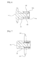
- FIG. 4 is a distal perspective view of the interspinous process device of this invention in the locked configuration
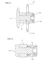
- FIG. 5 is a proximal perspective view of the interspinous process device of this invention in the locked configuration
- FIG. 6 is a cross-sectional view of the interspinous process device of this invention taken along lines 6 -6 of FIG. 3 ;
- FIG. 7 is a cross-sectional view of the interspinous process device of this invention taken along lines 7 - 7 of FIG. 3 ;
- FIG. 8 is a cross-sectional view of the interspinous process device of this invention taken along lines 8 - 8 of FIG. 5 ;
- FIG. 9 is a cross-sectional view of the interspinous process device of this invention taken along lines 9 - 9 of FIG. 5 ;
- FIG. 10 is an end elevation view of the proximal retention member of the interspinous process device of this invention.
- FIG. 11 is a schematic view of a portion of a human spine showing a dissected interspinous ligament in the space between adjacent spinous processes where the interspinous process device of this invention is to be implanted;
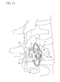
- FIGs. 12 - 15 are schematic illustrations of the interspinous process device of this invention and a portion of a human spine that illustrate the method of implanting the interspinous process device of this invention.
- proximal and distal refer to directions closer to and away from, respectively, an operator (e.g., surgeon, physician, nurse, technician, etc.) who would insert the medical device into the patient, with the tip-end (i.e., distal end) of the device inserted inside a patient's body first.
- an operator e.g., surgeon, physician, nurse, technician, etc.
- the tip-end i.e., distal end of the device inserted inside a patient's body first.
- the device end first inserted inside the patient's body would be the distal end of the device, while the device end last to enter the patient's body would be the proximal end of the device.
- the term "body” when used in connection with the location where the device of this invention is to be placed to treat lumbar spinal stenosis, or to teach or practice implantation methods for the device means a mammalian body.
- a body can be a patient's body, or a cadaver, or a portion of a patient's body or a portion of a cadaver.
- parallel describes a relationship, given normal manufacturing or measurement or similar tolerances, between two geometric constructions (e.g., two lines, two planes, a line and a plane, two curved surfaces, a line and a curved surface or the like) in which the two geometric constructions are substantially non-intersecting as they extend substantially to infinity.
- two geometric constructions e.g., two lines, two planes, a line and a plane, two curved surfaces, a line and a curved surface or the like
- a line is said to be parallel to a curved surface when the line and the curved surface do not intersect as they extend to infinity.
- planar surface i.e., a two-dimensional surface
- every point along the line is spaced apart from the nearest portion of the surface by a substantially equal distance.
- Two geometric constructions are described herein as being “parallel” or “substantially parallel” to each other when they are nominally parallel to each other, such as for example, when they are parallel to each other within a tolerance.
- tolerances can include, for example, manufacturing tolerances, measurement tolerances or the like.
- normal perpendicular
- orthoganal a relationship between two geometric constructions (e.g., two lines, two planes, a line and a plane, two curved surfaces, a line and a curved surface or the like) in which the two geometric constructions intersect at an angle of approximately 90 degrees within at least one plane.
- a line is said to be normal, perpendicular or orthoganal to a curved surface when the line and the curved surface intersect at an angle of approximately 90 degrees within a plane.
- Two geometric constructions are described herein as being “normal”, “perpendicular”, “orthogonal” or “substantially normal”, “substantially perpendicular”, “substantially orthogonal” to each other when they are nominally 90 degrees to each other, such as for example, when they are 90 degrees to each other within a tolerance.
- tolerances can include, for example, manufacturing tolerances, measurement tolerances or the like.
- the interspinous process device 10 of this invention includes (i) a main body portion 100 having a shaft 120 that is adapted to be disposed between adjacent spinous processes and a distal retention member 110 adapted to be disposed along a lateral side of a superior spinous process and an inferior spinous process, and (ii) a proximal retention member 200 adapted to be disposed along an opposite lateral side of the superior spinous process and the inferior spinous process.
- a damper ring 20 may also be located around shaft 120 of main body portion 100 between distal retention member 110 and proximal retention member 200.
- proximal portion of shaft 120 has a larger diameter than the remainder of shaft 120 to define a recessed area between distal retention member 110 and the proximal portion of shaft 120 into which damper ring 20 may fit. See e.g. FIG. 1 .
- Proximal retention member 200 includes a central portion 220 which defines a central lumen 225 into which a proximal portion of shaft 120 of main body portion 100 may be located so that proximal retention member 200 is rotatable with respect to main body portion 100.
- Distal retention member 110 includes a distal upper wing 111 and a distal lower wing 112.
- Distal upper wing 111 is adapted to engage a distal side of a superior spinous process when device 10 is appropriately located in the space between adjacent spinous processes such that the longitudinal axis of damper ring 20 is generally perpendicular to the sagittal plane. See for example FIG. 15 .
- distal lower wing 112 is adapted to engage a distal side of an inferior spinous process.
- distal retention member 110 has a generally elliptical configuration with a major axis A1 and a minor axis A2.
- distal retention member 110 presents a smaller dimension in a first direction than in a direction normal to the first direction.
- the dimension of distal retention member 110 along the major axis A1 is greater than the distance between adjacent spinous processes when they are distracted to the desired spacing.
- the dimension of distal retention member 110 along the minor axis A2 is about equal to the distance between the adjacent spinous processes when they are distracted to the desired spacing.
- the proximal portion of shaft 120 includes a slot 130 that cooperates with a complementary key 230 disposed within central lumen 225 of proximal retention member 200.
- a complementary key 230 disposed within central lumen 225 of proximal retention member 200.
- two slots 130 are located along the proximal portion of shaft 120 about 180 degrees apart. Even more preferably, slots 130 are aligned 180 degrees apart so that they are aligned along a line extending in a direction substantially parallel to the minor axis A2 of distal retention member 110.
- a plurality of lugs is also spaced around the periphery of shaft 120 adjacent to its proximal end. Preferably, these lugs are divided into two sets of lugs, which are spaced about 180 degrees apart such that each set is located between the pair of slots 130.
- upper lugs 151a and 151b are generally aligned with distal upper wing 111, while lower lugs 152a and 152b are generally aligned with distal lower wing 112.
- generally planar surfaces 135 are located along the proximal portion of shaft 120 about 180 degrees apart, with each of planar surfaces 135 located adjacent to one set of lugs between each of slots 130. Stated another way, planar surfaces 135 are substantially aligned along a line extending in a direction substantially parallel to major axis A1.
- Proximal retention member 200 includes a proximal upper wing 210 and a proximal lower wing 215, as well as a central portion 220 and central lumen 225. As shown herein, proximal retention member 200 has a generally elliptical configuration with a major axis A3 and a minor axis A4. Proximal retention member 200 is formed as a circumferential bar. However, proximal retention member 200 may have a solid configuration similar to distal retention member 110. In addition, distal retention member 110 may be formed as a circumferential bar similar to proximal retention member 200.
- proximal retention member 200 Although an elliptical configuration is preferred for the configuration of proximal retention member 200, any other geometrical shape may be used as long as proximal retention member 200 presents a smaller dimension in a first direction than in a direction normal to the first direction.
- the dimension of proximal retention member 200 along the major axis A3 is greater than the distance between adjacent spinous processes when they are distracted to the desired spacing.
- the length of proximal retention member 200 along major axis A3 is preferably greater than the length of distal retention member 110 along major axis A1. This greater dimension provides a visual cue for the surgeon so s/he can quickly determine which end is the proximal portion and which end is the distal portion.
- distal retention member 110 be relatively small to facilitate implantation of the device. Typically, there is less room on the distal side of the spinous processes for the surgeon to manipulate the device.
- a key 230 is formed in central lumen 225 in complementary receiving fashion with respect to slot 130.
- Preferably two such keys 230 are formed in central lumen 225 and are located about 180 degrees apart along the minor axis A4. This allows keys 230 to be aligned with planar surfaces 135 when the major axis A1 of distal retention member 110 extends in a direction that is normal to the major axis A3 of proximal retention member 200.
- annular groove 250 is formed along an internal surface of central lumen 225 along a proximal portion thereof.
- Annular groove 250 is formed to act as a guide for lugs 151a, 151b, 152a, and 152b. As such, lugs 151a, 151b, 152a, and 152b fit within annular groove 250 and can move along groove 250 as proximal retention member 200 rotates with respect to main body portion 100 about the longitudinal axis of main body portion 100.
- lugs 151a, 151b, 152a and 152b have tapered proximal ends to facilitate the movement of lugs 151a, 151b, 152a and 152b into annular groove 250 as main body portion 100 is moved in a direction along the longitudinal axis of shaft 120 into engagement with proximal retention member 200 during assembly of device 10.
- lugs 151a, 151b, 152a and 152b have a distal end that is substantially perpendicular to planar surface 135. This ensures that lugs 151a, 151b, 152a and 152b are difficult to remove from annular groove 250 and minimizes the possibility that main body portion 100 can be removed from proximal retention member 200 once device 10 is assembled.
- lugs 151a and 151b are separated a distance that is at least slightly greater than the width of key 230.
- lugs 152a and 152b are separated a distance that is at least slightly greater than the width of key 230. This allows keys 230 to move past lugs 151a, 151b, 152a and 152b during assembly such that keys 230 are adjacent planar surfaces 135.
- Planar surfaces 135 provide sufficient space between the wall of central lumen 225 to allow keys 230 and the proximal portion of shaft 120 to fit within central lumen 225.
- Key 230 and slot 130 are configured such that key 230 fits snugly within slot 130.
- key 230 fits snugly within slot 130.
- device 10 can be located between adjacent spinous processes with shaft 120 and damper ring 20 located between adjacent spinous process such that they are substantially perpendicular to and cross the sagittal plane, distal upper wing 111 and distal lower wing 112 are located along the distal portion of the superior and inferior spinous processes respectively, and proximal upper retention member 210 and proximal lower retention member 215 are located along the proximal portion of the superior and inferior spinous processes respectively. This prevents device 10 from migrating from that location after implantation.
- locking mechanism (i) allows relative rotation between main body portion 100 and proximal retention member 200, and (ii) locks main body portion 100 and proximal retention member 200 with respect to each other such that the major axis A1 of distal retention member 110 extends in the same direction as the major axis A3 of proximal retention member 200.
- proximal retention member 200 When device 10 is in the implantation configuration as shown for example in FIG. 3 , proximal retention member 200 is oriented such that major axis A3 is substantially normal to the orientation of major axis A1 of distal retention member 110, i.e. major axis A3 extends in a direction substantially normal to the direction of major axis A1.
- major axis A3 of proximal retention member 200 When device 10 is in its locked and final configuration as shown for example in FIG. 5 , major axis A3 of proximal retention member 200 extends in a direction that is substantially aligned with major axis A1 of distal retention member 110, i.e. major axis A3 extends in a direction substantially parallel to the direction of major axis A1.
- the arrangement of keys 230 and slots 130 allows main body portion 100 to be rotated with respect to proximal retention member 200 about 90 degrees in either a clockwise or counterclockwise direction between the initial implantation position and the final locked position.
- the interspinous ligament is typically dissected with a cutting instrument, such as a simple scalpel, an electrosurgical device or the like, not shown, to create an appropriately sized opening in the interspinous ligament to allow passage of a distal portion of device 10 therethrough. See FIG. 11 .
- a cutting instrument such as a simple scalpel, an electrosurgical device or the like, not shown, to create an appropriately sized opening in the interspinous ligament to allow passage of a distal portion of device 10 therethrough. See FIG. 11 .
- a cutting instrument such as a simple scalpel, an electrosurgical device or the like, not shown, to create an appropriately sized opening in the interspinous ligament to allow passage of a distal portion of device 10 therethrough. See FIG. 11 .
- This allows device 10 to be implanted in the space between adjacent spinous processes with a lateral approach. In most circumstances, the space between adjacent spinous processes may first need to be distracted with a distraction tool, not shown, to provide additional space and pain relief for the patient. After
- distal retention member 110 is inserted through the opening formed in the interspinous ligament. See FIG. 12 .
- Distal retention member 110 is oriented such that its major axis A1 is generally parallel to the axial plane, with minor axis A2 being generally parallel to the sagittal plane and the coronal plane. In this orientation, major axis A1 would not be parallel to or normal to the sagittal and coronal planes. See FIG. 12 . In this orientation, the dimension of distal retention member 110 along minor axis A2 does not hinder movement of device 10 through the space between adjacent spinous processes. Distal retention member 110 thus may be passed through the space between adjacent spinous processes with minimal disruption to the surrounding tissue.
- the supraspinous ligament remains undisturbed during the procedure. It may be necessary for a leading edge of distal retention member 110 to be first passed through the space between the adjacent interspinous processes, with major axis A1 not parallel to and not normal to the sagittal and coronal planes, in order to properly position device 10. Once the leading edge of distal retention member 110 passes through the space formed in the interspinous ligament, device 10 may be rotated about an axis normal to the longitudinal axis of implant 10 so the longitudinal axis of implant 10 becomes parallel to the coronal and axial planes and normal to the sagittal plane. Compare FIG. 12 with FIG. 13 .
- distal retention member 110 may have to be adjusted during the procedure in order to be properly placed in position.
- distal retention member 110 may have to be rotated around the (i) longitudinal axis of device 10, (ii) its major axis, and/or (iii) its minor axis during some portion or all of the implantation procedure. These manipulations may be necessary because of individual characteristics of the anatomy of the body into which device 10 is to be located.
- distal retention member 110 may be rotated with respect to proximal retention member 200 about the longitudinal axis of main body portion 100.
- Distal retention member 110 may be rotated either clockwise or counterclockwise. This locks distal retention member 110 with respect to proximal retention member 200 such that major axis A3 of proximal retention member 200 and major axis A1 of distal retention member 110 are oriented such that they extend in the same direction and thus are generally parallel to each other and the sagittal and coronal planes and generally normal to the axial plane.
- major axes A1 and A3 of distal retention member 110 and proximal retention member 200 respectively define a dimension that is greater than the distance between adjacent spinous processes, with the dimension for proximal retention member 200 preferably being greater.
- the distance between proximal retention member 200 and distal retention member 110 should be slightly greater than the distance between the distal side of the adjacent spinous process and the proximal side of the adjacent spinous processes. In this manner, device 10 is held in place by proximal retention member 200 and distal retention member 110.
- Device 10 can be constructed with various biocompatible materials such as, for example, titanium, titanium alloy, surgical steel, biocompatible metal alloys, stainless steel, Nitinol, plastic, polyetheretherketone (PEEK), carbon fiber, ultra-high molecular weight (UHMW) polyethylene, and other biocompatible polymeric materials.
- the material of device 10 can have, for example, a compressive strength similar to or higher than that of bone.
- damper ring 20, which is placed between the two adjacent spinous processes is formed from a material having an elastic modulus higher than the elastic modulus of the bone of the spinous processes.
- damper ring 20 is formed from a material having a higher elastic modulus than the materials used to form main body portion 100 and proximal retention member 200.
- damper ring 20 may have an elastic modulus higher than bone, while main body portion 100 and proximal retention member 100 have a lower elastic modulus than bone.
- damper ring 20 is formed of a compliant material, such as silicone, to dampen the shock when the spinal column is moved into extension.
Landscapes
- Health & Medical Sciences (AREA)
- Orthopedic Medicine & Surgery (AREA)
- Life Sciences & Earth Sciences (AREA)
- Neurology (AREA)
- Surgery (AREA)
- Heart & Thoracic Surgery (AREA)
- Engineering & Computer Science (AREA)
- Biomedical Technology (AREA)
- Nuclear Medicine, Radiotherapy & Molecular Imaging (AREA)
- Medical Informatics (AREA)
- Molecular Biology (AREA)
- Animal Behavior & Ethology (AREA)
- General Health & Medical Sciences (AREA)
- Public Health (AREA)
- Veterinary Medicine (AREA)
- Prostheses (AREA)
- Surgical Instruments (AREA)
Applications Claiming Priority (1)
| Application Number | Priority Date | Filing Date | Title |
|---|---|---|---|
| US12/607,917 US8771317B2 (en) | 2009-10-28 | 2009-10-28 | Interspinous process implant and method of implantation |
Publications (1)
| Publication Number | Publication Date |
|---|---|
| EP2316362A1 true EP2316362A1 (fr) | 2011-05-04 |
Family
ID=43245001
Family Applications (1)
| Application Number | Title | Priority Date | Filing Date |
|---|---|---|---|
| EP10189284A Withdrawn EP2316362A1 (fr) | 2009-10-28 | 2010-10-28 | Implant d'apophyse interépineuse |
Country Status (3)
| Country | Link |
|---|---|
| US (1) | US8771317B2 (fr) |
| EP (1) | EP2316362A1 (fr) |
| JP (1) | JP2011092712A (fr) |
Families Citing this family (11)
| Publication number | Priority date | Publication date | Assignee | Title |
|---|---|---|---|---|
| US7842074B2 (en) | 2007-02-26 | 2010-11-30 | Abdou M Samy | Spinal stabilization systems and methods of use |
| US8945184B2 (en) * | 2009-03-13 | 2015-02-03 | Spinal Simplicity Llc. | Interspinous process implant and fusion cage spacer |
| US8262697B2 (en) * | 2010-01-14 | 2012-09-11 | X-Spine Systems, Inc. | Modular interspinous fixation system and method |
| US20120215262A1 (en) * | 2011-02-16 | 2012-08-23 | Interventional Spine, Inc. | Spinous process spacer and implantation procedure |
| KR101066324B1 (ko) * | 2011-04-06 | 2011-09-20 | 유창화 | 척추 극돌기 간격 유지장치 |
| US20120323276A1 (en) | 2011-06-17 | 2012-12-20 | Bryan Okamoto | Expandable interspinous device |
| US9149306B2 (en) | 2011-06-21 | 2015-10-06 | Seaspine, Inc. | Spinous process device |
| US9364267B2 (en) | 2012-04-17 | 2016-06-14 | Aurora Spine, Inc. | Dynamic and non-dynamic interspinous fusion implant and bone growth stimulation system |
| WO2016137983A1 (fr) | 2015-02-24 | 2016-09-01 | X-Spine Systems, Inc. | Système de fixation interépineux modulaire à élément fileté |
| KR101952597B1 (ko) | 2017-02-13 | 2019-02-27 | (주)시지바이오 | 골대체 임플란트 |
| KR102446311B1 (ko) | 2017-05-02 | 2022-09-23 | 가톨릭대학교 산학협력단 | 골유합부재 및 이를 구비한 극돌기 임플란트 |
Citations (6)
| Publication number | Priority date | Publication date | Assignee | Title |
|---|---|---|---|---|
| WO1999021500A1 (fr) * | 1997-10-27 | 1999-05-06 | Saint Francis Medical Technologies, Llc | Implant de distraction vertebrale |
| US20060264938A1 (en) * | 2005-03-21 | 2006-11-23 | St. Francis Medical Technologies, Inc. | Interspinous process implant having deployable wing and method of implantation |
| US20080114456A1 (en) * | 2006-11-15 | 2008-05-15 | Warsaw Orthopedic, Inc. | Spinal implant system |
| US20080114455A1 (en) * | 2006-11-15 | 2008-05-15 | Warsaw Orthopedic, Inc. | Rotating Interspinous Process Devices and Methods of Use |
| US20080177271A1 (en) * | 2006-04-07 | 2008-07-24 | Chung-Chun Yeh | Interspinous process distraction device |
| US20080208344A1 (en) * | 2007-02-06 | 2008-08-28 | Kilpela Thomas S | Intervertebral Implant Devices and Methods for Insertion Thereof |
Family Cites Families (286)
| Publication number | Priority date | Publication date | Assignee | Title |
|---|---|---|---|---|
| US624969A (en) | 1899-05-16 | Peter peterson | ||
| US1153797A (en) | 1915-04-29 | 1915-09-14 | Jules Emile Kegreisz | Expansion-anchor. |
| US1516347A (en) | 1923-08-30 | 1924-11-18 | Pataky Anton | Coupling pin |
| US2077804A (en) | 1936-05-19 | 1937-04-20 | Morrison Gordon Monroe | Device for treating fractures of the neck of the femur |
| US2299308A (en) | 1941-08-15 | 1942-10-20 | Russell A Creighton | Self-locking spike |
| US2485531A (en) | 1948-01-13 | 1949-10-18 | Dzus William | Surgical toggle bolt |
| US2607370A (en) | 1948-07-13 | 1952-08-19 | Oscar F Anderson | Pipe plug |
| US2685877A (en) | 1952-03-20 | 1954-08-10 | Dobelle Martin | Femoral head prosthesis |
| US2677369A (en) | 1952-03-26 | 1954-05-04 | Fred L Knowles | Apparatus for treatment of the spinal column |
| US3065659A (en) | 1959-09-28 | 1962-11-27 | Superior Concrete Accessories | Expansion bolt |
| US3426364A (en) | 1966-08-25 | 1969-02-11 | Colorado State Univ Research F | Prosthetic appliance for replacing one or more natural vertebrae |
| US3648691A (en) | 1970-02-24 | 1972-03-14 | Univ Colorado State Res Found | Method of applying vertebral appliance |
| DE2112139B2 (de) | 1971-03-13 | 1973-02-01 | Fischer, Artur, 7241 Tumhngen | Huelsenfoermiges verbindungselement fuer die kompressions-osteosynthese bei roehrenknochenfrakturen |
| US4011602A (en) | 1975-10-06 | 1977-03-15 | Battelle Memorial Institute | Porous expandable device for attachment to bone tissue |
| US4704057A (en) | 1976-09-15 | 1987-11-03 | Mechanical Plastics Corp. | Fastening element |
| PL114098B1 (en) | 1978-04-14 | 1981-01-31 | Wyzsza Szkola Inzynierska | Apparatus for correcting spinal curvature |
| US4274324A (en) | 1978-04-18 | 1981-06-23 | Giannuzzi Louis | Hollow wall screw anchor |
| CH628803A5 (en) | 1978-05-12 | 1982-03-31 | Sulzer Ag | Implant insertable between adjacent vertebrae |
| US4237875A (en) | 1979-02-23 | 1980-12-09 | Towmotor Corporation | Dynamic intramedullary compression nailing |
| US4289123A (en) | 1980-03-31 | 1981-09-15 | Dunn Harold K | Orthopedic appliance |
| GB2083754B (en) | 1980-09-15 | 1984-04-26 | Rezaian Seyed Mahmoud | Spinal fixator |
| SU988281A1 (ru) | 1981-06-26 | 1983-01-15 | За витель | Устройство дл фиксации позвоночника |
| US4646998A (en) | 1981-11-20 | 1987-03-03 | Clairson International Corporation | Wall-mounted shelf support clip |
| US4519100A (en) | 1982-09-30 | 1985-05-28 | Orthopedic Equipment Co. Inc. | Distal locking intramedullary nail |
| US4822226A (en) | 1983-08-08 | 1989-04-18 | Kennedy Arvest G | Wing nut retainer and extractor |
| US4554914A (en) | 1983-10-04 | 1985-11-26 | Kapp John P | Prosthetic vertebral body |
| US4553273A (en) | 1983-11-23 | 1985-11-19 | Henry Ford Hospital | Vertebral body prosthesis and spine stabilizing method |
| GB8333442D0 (en) | 1983-12-15 | 1984-01-25 | Showell A W Sugicraft Ltd | Devices for spinal fixation |
| US4611582A (en) | 1983-12-27 | 1986-09-16 | Wisconsin Alumni Research Foundation | Vertebral clamp |
| US4604995A (en) | 1984-03-30 | 1986-08-12 | Stephens David C | Spinal stabilizer |
| US4573454A (en) | 1984-05-17 | 1986-03-04 | Hoffman Gregory A | Spinal fixation apparatus |
| FR2575059B1 (fr) | 1984-12-21 | 1988-11-10 | Daher Youssef | Dispositif d'etaiement utilisable dans une prothese vertebrale |
| US4632101A (en) | 1985-01-31 | 1986-12-30 | Yosef Freedland | Orthopedic fastener |
| US4636217A (en) | 1985-04-23 | 1987-01-13 | Regents Of The University Of Minnesota | Anterior spinal implant |
| US4599086A (en) | 1985-06-07 | 1986-07-08 | Doty James R | Spine stabilization device and method |
| SE458417B (sv) | 1985-08-15 | 1989-04-03 | Sven Olerud | Fixationsinstrument avsett foer anvaendning vid ryggoperationer |
| US4662808A (en) | 1985-10-02 | 1987-05-05 | Lee-Rowan Company | Wall anchor |
| US4931055A (en) | 1986-05-30 | 1990-06-05 | John Bumpus | Distraction rods |
| GB8620937D0 (en) | 1986-08-29 | 1986-10-08 | Shepperd J A N | Spinal implant |
| US4787378A (en) | 1986-09-08 | 1988-11-29 | Sodhi Jitendra S | Self-retaining nail for fracture of neck of femur |
| US4969887A (en) | 1986-09-08 | 1990-11-13 | Sodhi Jitendra S | Self-retaining nail kit for repairing a fractured neck of femur |
| CA1283501C (fr) | 1987-02-12 | 1991-04-30 | Thomas P. Hedman | Disque artificiel pour colonne vertebrale |
| SU1484348A1 (ru) | 1987-03-04 | 1989-06-07 | Белорусский научно-исследовательский институт травматологии и ортопедии | Фиксатор позвоночника |
| FR2623085B1 (fr) | 1987-11-16 | 1992-08-14 | Breard Francis | Implant chirurgical pour limiter le mouvement relatif des vertebres |
| FR2625097B1 (fr) | 1987-12-23 | 1990-05-18 | Cote Sarl | Prothese inter-epineuse composee dans une matiere semi-elastique et comportant un oeillet de transfilage a son extremite et de coussinets inter-epineux |
| US5609635A (en) | 1988-06-28 | 1997-03-11 | Michelson; Gary K. | Lordotic interbody spinal fusion implants |
| US4892545A (en) | 1988-07-14 | 1990-01-09 | Ohio Medical Instrument Company, Inc. | Vertebral lock |
| IT215084Z2 (it) | 1988-08-03 | 1990-07-30 | Torino A | Cambra ad escursione variabile |
| US4834600A (en) | 1988-08-25 | 1989-05-30 | Lemke Stuart H | Fastener assembly |
| GB8825909D0 (en) | 1988-11-04 | 1988-12-07 | Showell A W Sugicraft Ltd | Pedicle engaging means |
| US5201734A (en) | 1988-12-21 | 1993-04-13 | Zimmer, Inc. | Spinal locking sleeve assembly |
| US4886405A (en) | 1989-01-27 | 1989-12-12 | Blomberg Ingvar M | Wall mounting device |
| FR2642645B1 (fr) | 1989-02-03 | 1992-08-14 | Breard Francis | Stabilisateur intervertebral souple ainsi que procede et appareillage pour le controle de sa tension avant mise en place sur le rachis |
| US5098433A (en) | 1989-04-12 | 1992-03-24 | Yosef Freedland | Winged compression bolt orthopedic fastener |
| DE3922044A1 (de) | 1989-07-05 | 1991-02-07 | Richter Turtur Matthias Dr | Instrumentarium zur wirbelbruchbehandlung |
| US4932975A (en) | 1989-10-16 | 1990-06-12 | Vanderbilt University | Vertebral prosthesis |
| US5059193A (en) | 1989-11-20 | 1991-10-22 | Spine-Tech, Inc. | Expandable spinal implant and surgical method |
| US5345927A (en) | 1990-03-02 | 1994-09-13 | Bonutti Peter M | Arthroscopic retractors |
| US5454365A (en) | 1990-11-05 | 1995-10-03 | Bonutti; Peter M. | Mechanically expandable arthroscopic retractors |
| DE4012622C1 (en) | 1990-04-20 | 1991-07-18 | Eska Medical Luebeck Medizintechnik Gmbh & Co, 2400 Luebeck, De | Two-part metal vertebra implant - has parts locked by two toothed racks, pre-stressed by elastic cushion between both implant parts |
| US5047055A (en) | 1990-12-21 | 1991-09-10 | Pfizer Hospital Products Group, Inc. | Hydrogel intervertebral disc nucleus |
| US5171278A (en) | 1991-02-22 | 1992-12-15 | Madhavan Pisharodi | Middle expandable intervertebral disk implants |
| WO1992014423A1 (fr) | 1991-02-22 | 1992-09-03 | Pisharodi Madhavan | Implant de disque intervertebral a expansion mediane et procede |
| US5390683A (en) | 1991-02-22 | 1995-02-21 | Pisharodi; Madhavan | Spinal implantation methods utilizing a middle expandable implant |
| DE4128332A1 (de) | 1991-08-27 | 1993-03-04 | Man Ceramics Gmbh | Wirbelknochenersatz |
| US5290312A (en) | 1991-09-03 | 1994-03-01 | Alphatec | Artificial vertebral body |
| FR2681525A1 (fr) | 1991-09-19 | 1993-03-26 | Medical Op | Dispositif de stabilisation souple ou semi rigide du rachis notamment humain par voie posterieure. |
| CH686610A5 (de) | 1991-10-18 | 1996-05-15 | Pina Vertriebs Ag | Kompressionsimplantat. |
| DE4208116C2 (de) | 1992-03-13 | 1995-08-03 | Link Waldemar Gmbh Co | Bandscheibenendoprothese |
| US5312405A (en) | 1992-07-06 | 1994-05-17 | Zimmer, Inc. | Spinal rod coupler |
| FR2693364B1 (fr) | 1992-07-07 | 1995-06-30 | Erpios Snc | Prothese intervertebrale permettant une stabilisation des contraintes rotatoires et de flexion-extension. |
| FR2695026B1 (fr) | 1992-08-25 | 1994-10-28 | Alexandre Worcel | Dispositif pour le maintien en compression d'un os fracturé. |
| DE9213656U1 (de) | 1992-10-09 | 1992-12-03 | Angiomed AG, 7500 Karlsruhe | Stent-Set |
| US5562735A (en) | 1992-11-09 | 1996-10-08 | Hospital For Joint Diseases | Spinal stabilization system and improved method |
| US5702395A (en) | 1992-11-10 | 1997-12-30 | Sofamor S.N.C. | Spine osteosynthesis instrumentation for an anterior approach |
| DE69330909T2 (de) | 1992-11-12 | 2002-06-20 | Neville Alleyne | Einrichtung zum schutz des herzens |
| US5306275A (en) | 1992-12-31 | 1994-04-26 | Bryan Donald W | Lumbar spine fixation apparatus and method |
| US5527314A (en) | 1993-01-04 | 1996-06-18 | Danek Medical, Inc. | Spinal fixation system |
| US5540703A (en) | 1993-01-06 | 1996-07-30 | Smith & Nephew Richards Inc. | Knotted cable attachment apparatus formed of braided polymeric fibers |
| US5496318A (en) | 1993-01-08 | 1996-03-05 | Advanced Spine Fixation Systems, Inc. | Interspinous segmental spine fixation device |
| FR2700941A1 (fr) | 1993-02-03 | 1994-08-05 | Felman Daniel | Implant de fixation intervertébral interépineux monobloc. |
| US5415661A (en) | 1993-03-24 | 1995-05-16 | University Of Miami | Implantable spinal assist device |
| FR2703239B1 (fr) | 1993-03-30 | 1995-06-02 | Brio Bio Rhone Implant Medical | Agrafe pour prothèse inter-épineuse. |
| EP0621020A1 (fr) | 1993-04-21 | 1994-10-26 | SULZER Medizinaltechnik AG | Prothèse intervertébrale et procédé d'implantation d'une telle prothèse |
| FR2707864B1 (fr) | 1993-07-23 | 1996-07-19 | Jean Taylor | Pince chirurgicale pour la mise en tension d'un ligament d'ostéosynthèse. |
| US5360430A (en) | 1993-07-29 | 1994-11-01 | Lin Chih I | Intervertebral locking device |
| US5458641A (en) | 1993-09-08 | 1995-10-17 | Ramirez Jimenez; Juan J. | Vertebral body prosthesis |
| US5439463A (en) | 1993-11-12 | 1995-08-08 | Lin; Chih-I | Spinal clamping device |
| US5454812A (en) | 1993-11-12 | 1995-10-03 | Lin; Chih-I | Spinal clamping device having multiple distance adjusting strands |
| US5403316A (en) | 1993-12-02 | 1995-04-04 | Danek Medical, Inc. | Triangular construct for spinal fixation |
| FR2715293B1 (fr) | 1994-01-26 | 1996-03-22 | Biomat | Cage intersomatique vertébrale. |
| US5474561A (en) * | 1994-02-01 | 1995-12-12 | Yao; Meei-Huei | All positional and universal guiding device for interlocking intramedullary nail |
| US5653762A (en) | 1994-03-18 | 1997-08-05 | Pisharodi; Madhavan | Method of stabilizing adjacent vertebrae with rotating, lockable, middle-expanded intervertebral disk stabilizer |
| FR2717675B1 (fr) | 1994-03-24 | 1996-05-03 | Jean Taylor | Cale inter-épineuse. |
| FR2719763B1 (fr) | 1994-05-11 | 1996-09-27 | Jean Taylor | Implant vertébral. |
| FR2721501B1 (fr) | 1994-06-24 | 1996-08-23 | Fairant Paulette | Prothèses des facettes articulaires vertébrales. |
| DE4423257C2 (de) | 1994-07-02 | 2001-07-12 | Ulrich Heinrich | Implantat zum Einsetzen zwischen Wirbelkörper der Wirbelsäule als Platzhalter |
| FR2722087A1 (fr) | 1994-07-08 | 1996-01-12 | Cahlik Marc Andre | Implant chirurgical intervetebral pour stabilisation et limitation des mouvements relatifs des vertebres |
| FR2722088B1 (fr) | 1994-07-08 | 1998-01-23 | Cahlik Marc Andre | Implant chirurgical de stabilisation de l'espace intervertebral |
| FR2722980B1 (fr) | 1994-07-26 | 1996-09-27 | Samani Jacques | Implant vertebral inter-epineux |
| DE9413471U1 (de) | 1994-08-20 | 1995-12-21 | Schäfer micomed GmbH, 73614 Schorndorf | Ventrales Zwischenwirbelimplantat |
| DE69522060T2 (de) | 1994-09-08 | 2002-05-29 | Stryker Technologies Corp., Kalamazoo | Bandscheibenkern aus Hydrogel |
| FR2724554B1 (fr) | 1994-09-16 | 1997-01-24 | Voydeville Gilles | Dispositif de fixation d'une prothese ligamentaire |
| ES2216021T3 (es) | 1994-10-17 | 2004-10-16 | Raymedica, Inc. | Nucleo del disco espinal protesico. |
| FR2725892A1 (fr) | 1994-10-21 | 1996-04-26 | Felman Daniel | Crochet vertebral a effet memoire de forme |
| FR2728159B1 (fr) | 1994-12-16 | 1997-06-27 | Tornier Sa | Prothese discale elastique |
| FR2729556B1 (fr) | 1995-01-23 | 1998-10-16 | Sofamor | Dispositif d'osteosynthese rachidienne a crochet median et appuis d'ancrage vertebral |
| US5665122A (en) | 1995-01-31 | 1997-09-09 | Kambin; Parviz | Expandable intervertebral cage and surgical method |
| FR2730156B1 (fr) | 1995-02-03 | 1997-04-30 | Textile Hi Tec | Cale inter epineuse |
| FR2730158B1 (fr) | 1995-02-06 | 1999-11-26 | Jbs Sa | Dispositif de maintien d'un ecartement normal entre les vertebres et destine au remplacement de vertebres manquantes |
| US5658335A (en) | 1995-03-09 | 1997-08-19 | Cohort Medical Products Group, Inc. | Spinal fixator |
| FR2731643A1 (fr) | 1995-03-16 | 1996-09-20 | Jbs Sa | Dispositif de tournevis angulaire pour le vissage et le devissage de vis difficilement accessibles, notamment dans le domaine chirurgical |
| US5630816A (en) | 1995-05-01 | 1997-05-20 | Kambin; Parviz | Double barrel spinal fixation system and method |
| WO1996039090A1 (fr) | 1995-06-06 | 1996-12-12 | Sdgi Holdings, Inc. | Dispositif servant a relier des tiges voisines pour instruments utilises en chirurgie spinale |
| US5690649A (en) | 1995-12-05 | 1997-11-25 | Li Medical Technologies, Inc. | Anchor and anchor installation tool and method |
| US5653763A (en) | 1996-03-29 | 1997-08-05 | Fastenetix, L.L.C. | Intervertebral space shape conforming cage device |
| CA2229382A1 (fr) | 1996-06-18 | 1997-12-24 | Marc D. Grynpas | Dispositif de fixation d'une prothese dans une cavite osseuse et ses procedes d'utilisation |
| US5746762A (en) | 1996-06-24 | 1998-05-05 | Bass; Lawrence S. | Device and method for surgical flap dissection |
| US5702455A (en) | 1996-07-03 | 1997-12-30 | Saggar; Rahul | Expandable prosthesis for spinal fusion |
| US5849004A (en) | 1996-07-17 | 1998-12-15 | Bramlet; Dale G. | Surgical anchor |
| US5716416A (en) | 1996-09-10 | 1998-02-10 | Lin; Chih-I | Artificial intervertebral disk and method for implanting the same |
| US5810815A (en) | 1996-09-20 | 1998-09-22 | Morales; Jose A. | Surgical apparatus for use in the treatment of spinal deformities |
| US6190414B1 (en) | 1996-10-31 | 2001-02-20 | Surgical Dynamics Inc. | Apparatus for fusion of adjacent bone structures |
| US5893850A (en) | 1996-11-12 | 1999-04-13 | Cachia; Victor V. | Bone fixation device |
| DE19652608C1 (de) | 1996-12-18 | 1998-08-27 | Eska Implants Gmbh & Co | Prophylaxe-Implantat gegen Frakturen osteoporotisch befallener Knochensegmente |
| US7306628B2 (en) | 2002-10-29 | 2007-12-11 | St. Francis Medical Technologies | Interspinous process apparatus and method with a selectably expandable spacer |
| US5836948A (en) | 1997-01-02 | 1998-11-17 | Saint Francis Medical Technologies, Llc | Spine distraction implant and method |
| US20050245937A1 (en) | 2004-04-28 | 2005-11-03 | St. Francis Medical Technologies, Inc. | System and method for insertion of an interspinous process implant that is rotatable in order to retain the implant relative to the spinous processes |
| US7101375B2 (en) | 1997-01-02 | 2006-09-05 | St. Francis Medical Technologies, Inc. | Spine distraction implant |
| US7959652B2 (en) | 2005-04-18 | 2011-06-14 | Kyphon Sarl | Interspinous process implant having deployable wings and method of implantation |
| US20020143331A1 (en) | 1998-10-20 | 2002-10-03 | Zucherman James F. | Inter-spinous process implant and method with deformable spacer |
| US6451019B1 (en) | 1998-10-20 | 2002-09-17 | St. Francis Medical Technologies, Inc. | Supplemental spine fixation device and method |
| US6695842B2 (en) | 1997-10-27 | 2004-02-24 | St. Francis Medical Technologies, Inc. | Interspinous process distraction system and method with positionable wing and method |
| US5860977A (en) | 1997-01-02 | 1999-01-19 | Saint Francis Medical Technologies, Llc | Spine distraction implant and method |
| US7201751B2 (en) | 1997-01-02 | 2007-04-10 | St. Francis Medical Technologies, Inc. | Supplemental spine fixation device |
| US5725341A (en) | 1997-01-08 | 1998-03-10 | Hofmeister; Oskar | Self fusing fastener |
| US20070282443A1 (en) | 1997-03-07 | 2007-12-06 | Disc-O-Tech Medical Technologies Ltd. | Expandable element |
| IL128261A0 (en) | 1999-01-27 | 1999-11-30 | Disc O Tech Medical Tech Ltd | Expandable element |
| WO2001054598A1 (fr) | 1998-03-06 | 2001-08-02 | Disc-O-Tech Medical Technologies, Ltd. | Implants osseux expansibles |
| DE69839051T2 (de) | 1997-03-07 | 2009-01-15 | Disc-O-Tech Medical Technologies, Ltd. | Systeme zur perkutanen knochen und wirbelstabilisirung,befestigung und reparatur |
| US6022376A (en) | 1997-06-06 | 2000-02-08 | Raymedica, Inc. | Percutaneous prosthetic spinal disc nucleus and method of manufacture |
| ATE380509T1 (de) | 1997-10-27 | 2007-12-15 | St Francis Medical Tech Inc | Wirbelsäulen distraktionsimplantat |
| US5980523A (en) | 1998-01-08 | 1999-11-09 | Jackson; Roger | Transverse connectors for spinal rods |
| FR2774581B1 (fr) | 1998-02-10 | 2000-08-11 | Dimso Sa | Stabilisateur interepineux a fixer a des apophyses epineuses de deux vertebres |
| FR2775183B1 (fr) | 1998-02-20 | 2000-08-04 | Jean Taylor | Prothese inter-epineuse |
| DE19816782A1 (de) | 1998-04-16 | 1999-10-28 | Ulrich Gmbh & Co Kg | Implantat zum Einsetzen zwischen Wirbelkörper der Wirbelsäule |
| DE19818143A1 (de) | 1998-04-23 | 1999-10-28 | Medinorm Ag | Vorrichtung zur Verbindung von Wirbeln der Wirbelsäule |
| US6126689A (en) | 1998-06-15 | 2000-10-03 | Expanding Concepts, L.L.C. | Collapsible and expandable interbody fusion device |
| US6264658B1 (en) | 1998-07-06 | 2001-07-24 | Solco Surgical Instruments Co., Ltd. | Spine fixing apparatus |
| US6352537B1 (en) | 1998-09-17 | 2002-03-05 | Electro-Biology, Inc. | Method and apparatus for spinal fixation |
| US7029473B2 (en) | 1998-10-20 | 2006-04-18 | St. Francis Medical Technologies, Inc. | Deflectable spacer for use as an interspinous process implant and method |
| US6554833B2 (en) | 1998-10-26 | 2003-04-29 | Expanding Orthopedics, Inc. | Expandable orthopedic device |
| US6261289B1 (en) | 1998-10-26 | 2001-07-17 | Mark Levy | Expandable orthopedic device |
| JP4128748B2 (ja) | 1998-10-30 | 2008-07-30 | ロス グリッグス,イアン | 髄内骨固定装置 |
| BR9805340B1 (pt) | 1998-12-14 | 2009-01-13 | inserto de expansço variÁvel para estabilizaÇço de coluna vertebral. | |
| US7081120B2 (en) | 1999-04-26 | 2006-07-25 | Sdgi Holdings, Inc. | Instrumentation and method for delivering an implant into a vertebral space |
| US6214050B1 (en) | 1999-05-11 | 2001-04-10 | Donald R. Huene | Expandable implant for inter-bone stabilization and adapted to extrude osteogenic material, and a method of stabilizing bones while extruding osteogenic material |
| US6520991B2 (en) | 1999-05-11 | 2003-02-18 | Donald R. Huene | Expandable implant for inter-vertebral stabilization, and a method of stabilizing vertebrae |
| US6419704B1 (en) | 1999-10-08 | 2002-07-16 | Bret Ferree | Artificial intervertebral disc replacement methods and apparatus |
| US6770096B2 (en) | 1999-07-01 | 2004-08-03 | Spinevision S.A. | Interbody spinal stabilization cage and spinal stabilization method |
| CA2425951C (fr) | 1999-08-18 | 2008-09-16 | Intrinsic Therapeutics, Inc. | Dispositifs et procede permettant d'augmenter ou de conserver un noyau gelatineux |
| FR2799640B1 (fr) | 1999-10-15 | 2002-01-25 | Spine Next Sa | Implant intervetebral |
| FR2799948B1 (fr) | 1999-10-22 | 2002-03-29 | Transco Esquisse | Barre de liaison pour l'ancrage d'une prothese inter epineuse |
| ES2241331T3 (es) | 1999-11-11 | 2005-10-16 | Synthes Ag Chur | Clavo intramedular de expansion radial. |
| US6293949B1 (en) | 2000-03-01 | 2001-09-25 | Sdgi Holdings, Inc. | Superelastic spinal stabilization system and method |
| US6336930B1 (en) | 2000-03-07 | 2002-01-08 | Zimmer, Inc. | Polymer filled bone plate |
| FR2806616B1 (fr) | 2000-03-21 | 2003-04-11 | Cousin Biotech | Cale interepineuse et dispositif de fixation sur le sacrum |
| US6402750B1 (en) | 2000-04-04 | 2002-06-11 | Spinlabs, Llc | Devices and methods for the treatment of spinal disorders |
| US6645207B2 (en) | 2000-05-08 | 2003-11-11 | Robert A. Dixon | Method and apparatus for dynamized spinal stabilization |
| US6730123B1 (en) * | 2000-06-22 | 2004-05-04 | Proteus Vision, Llc | Adjustable intraocular lens |
| US6964667B2 (en) | 2000-06-23 | 2005-11-15 | Sdgi Holdings, Inc. | Formed in place fixation system with thermal acceleration |
| FR2811540B1 (fr) | 2000-07-12 | 2003-04-25 | Spine Next Sa | Implant intervertebral amortissant |
| EP1331906A2 (fr) | 2000-10-25 | 2003-08-06 | SDGI Holdings, Inc. | Dispositif de fusion de corps intervertebraux a expansion verticale |
| US6582467B1 (en) | 2000-10-31 | 2003-06-24 | Vertelink Corporation | Expandable fusion cage |
| FR2816197B1 (fr) | 2000-11-07 | 2003-01-10 | Jean Taylor | Prothese inter-epineuse, outil et procede pour sa preparation |
| US6666891B2 (en) | 2000-11-13 | 2003-12-23 | Frank H. Boehm, Jr. | Device and method for lumbar interbody fusion |
| US6579319B2 (en) | 2000-11-29 | 2003-06-17 | Medicinelodge, Inc. | Facet joint replacement |
| US6743257B2 (en) | 2000-12-19 | 2004-06-01 | Cortek, Inc. | Dynamic implanted intervertebral spacer |
| FR2818530B1 (fr) | 2000-12-22 | 2003-10-31 | Spine Next Sa | Implant intervertebral a cale deformable |
| GB0102141D0 (en) | 2001-01-27 | 2001-03-14 | Davies John B C | Improvements in or relating to expandable bone nails |
| US6364883B1 (en) | 2001-02-23 | 2002-04-02 | Albert N. Santilli | Spinous process clamp for spinal fusion and method of operation |
| FR2822051B1 (fr) | 2001-03-13 | 2004-02-27 | Spine Next Sa | Implant intervertebral a fixation auto-bloquante |
| US6582433B2 (en) | 2001-04-09 | 2003-06-24 | St. Francis Medical Technologies, Inc. | Spine fixation device and method |
| EP1427341A1 (fr) | 2001-07-20 | 2004-06-16 | Spinal Concepts Inc. | Systeme et procede de stabilisation des vertebres |
| US6375682B1 (en) | 2001-08-06 | 2002-04-23 | Lewis W. Fleischmann | Collapsible, rotatable and expandable spinal hydraulic prosthetic device |
| FR2828398B1 (fr) | 2001-08-08 | 2003-09-19 | Jean Taylor | Ensemble de stabilisation de vertebres |
| CA2495119C (fr) | 2001-08-20 | 2010-02-02 | Synthes (U.S.A.) | Prothese intervertebrale |
| US20030114853A1 (en) | 2001-10-12 | 2003-06-19 | Ian Burgess | Polyaxial cross connector |
| FR2832917B1 (fr) | 2001-11-30 | 2004-09-24 | Spine Next Sa | Implant intervertebral a cale elastiquement deformable |
| AU2002360783A1 (en) | 2001-12-27 | 2003-07-24 | Osteotech Inc. | Orthopedic/neurosurgical system and method for securing vertebral bone facets |
| FR2835173B1 (fr) | 2002-01-28 | 2004-11-05 | Biomet Merck France | Implant vertebral inter-epineux |
| US6733534B2 (en) | 2002-01-29 | 2004-05-11 | Sdgi Holdings, Inc. | System and method for spine spacing |
| US6923830B2 (en) | 2002-02-02 | 2005-08-02 | Gary K. Michelson | Spinal fusion implant having deployable bone engaging projections |
| JP3708883B2 (ja) | 2002-02-08 | 2005-10-19 | 昭和医科工業株式会社 | 椎体間隔保持具 |
| EP1346708A1 (fr) | 2002-03-20 | 2003-09-24 | A-Spine Holding Group Corp. | Dispositif spinal de fixation avec trois crochets |
| US7048736B2 (en) * | 2002-05-17 | 2006-05-23 | Sdgi Holdings, Inc. | Device for fixation of spinous processes |
| US20030220643A1 (en) | 2002-05-24 | 2003-11-27 | Ferree Bret A. | Devices to prevent spinal extension |
| FR2844179B1 (fr) | 2002-09-10 | 2004-12-03 | Jean Taylor | Ensemble de soutien vertebral posterieur |
| US20060064165A1 (en) | 2004-09-23 | 2006-03-23 | St. Francis Medical Technologies, Inc. | Interspinous process implant including a binder and method of implantation |
| US7833246B2 (en) | 2002-10-29 | 2010-11-16 | Kyphon SÀRL | Interspinous process and sacrum implant and method |
| US7549999B2 (en) | 2003-05-22 | 2009-06-23 | Kyphon Sarl | Interspinous process distraction implant and method of implantation |
| US6723126B1 (en) | 2002-11-01 | 2004-04-20 | Sdgi Holdings, Inc. | Laterally expandable cage |
| US6685742B1 (en) | 2002-11-12 | 2004-02-03 | Roger P. Jackson | Articulated anterior expandable spinal fusion cage system |
| WO2004047689A1 (fr) | 2002-11-21 | 2004-06-10 | Sdgi Holdings, Inc. | Systemes et techniques de stabilisation rachidienne intravertebrale au moyen de dispositifs dilatables |
| EP1575459B1 (fr) | 2002-11-21 | 2008-05-21 | Warsaw Orthopedic, Inc. | Systemes pour la stabilisation intervertebrale au moyen de dispositifs extensibles |
| FR2850009B1 (fr) | 2003-01-20 | 2005-12-23 | Spine Next Sa | Ensemble de traitement de la degenerescence d'un disque intervertebral |
| US7335203B2 (en) | 2003-02-12 | 2008-02-26 | Kyphon Inc. | System and method for immobilizing adjacent spinous processes |
| FR2851154B1 (fr) | 2003-02-19 | 2006-07-07 | Sdgi Holding Inc | Dispositif inter-epineux pour freiner les mouvements de deux vertebres successives, et procede de fabrication d'un coussin lui etant destine |
| US7824444B2 (en) | 2003-03-20 | 2010-11-02 | Spineco, Inc. | Expandable spherical spinal implant |
| ITFI20030084A1 (it) | 2003-03-28 | 2004-09-29 | Cousin Biotech S A S | Protesi vertebrale interlaminare |
| KR100582768B1 (ko) | 2003-07-24 | 2006-05-23 | 최병관 | 척추 가시돌기 삽입용 보철물 |
| CN2638760Y (zh) | 2003-08-04 | 2004-09-08 | 邹德威 | 用于在椎体中形成空腔的扩张器 |
| US7377942B2 (en) | 2003-08-06 | 2008-05-27 | Warsaw Orthopedic, Inc. | Posterior elements motion restoring device |
| FR2861286B1 (fr) | 2003-10-24 | 2007-07-06 | Cousin Biotech | Support inter-lamaire |
| ATE363250T1 (de) | 2003-11-07 | 2007-06-15 | Impliant Ltd | Wirbelsäulenprothesen |
| WO2005048856A1 (fr) | 2003-11-10 | 2005-06-02 | Umc Utrecht Holding B.V. | Implant dilatable pour le traitement d'os fracture and/ou d'os affaisse |
| US7217293B2 (en) | 2003-11-21 | 2007-05-15 | Warsaw Orthopedic, Inc. | Expandable spinal implant |
| US20050209603A1 (en) * | 2003-12-02 | 2005-09-22 | St. Francis Medical Technologies, Inc. | Method for remediation of intervertebral disks |
| US20050165398A1 (en) | 2004-01-26 | 2005-07-28 | Reiley Mark A. | Percutaneous spine distraction implant systems and methods |
| US7641664B2 (en) | 2004-02-12 | 2010-01-05 | Warsaw Orthopedic, Inc. | Surgical instrumentation and method for treatment of a spinal structure |
| US8636802B2 (en) | 2004-03-06 | 2014-01-28 | DePuy Synthes Products, LLC | Dynamized interspinal implant |
| US7458981B2 (en) | 2004-03-09 | 2008-12-02 | The Board Of Trustees Of The Leland Stanford Junior University | Spinal implant and method for restricting spinal flexion |
| US7763073B2 (en) | 2004-03-09 | 2010-07-27 | Depuy Spine, Inc. | Posterior process dynamic spacer |
| US7507241B2 (en) | 2004-04-05 | 2009-03-24 | Expanding Orthopedics Inc. | Expandable bone device |
| FR2870107B1 (fr) | 2004-05-11 | 2007-07-27 | Spine Next Sa | Dispositif autobloquant de fixation d'un implant intervertebral |
| SG142309A1 (en) | 2004-05-17 | 2008-05-28 | Wooridul Spine Health Inst Co | Spine insert |
| US7585316B2 (en) | 2004-05-21 | 2009-09-08 | Warsaw Orthopedic, Inc. | Interspinous spacer |
| FR2871366A1 (fr) | 2004-06-09 | 2005-12-16 | Ceravic Soc Par Actions Simpli | Implant expansible prothetique osseux |
| US7776091B2 (en) | 2004-06-30 | 2010-08-17 | Depuy Spine, Inc. | Adjustable posterior spinal column positioner |
| US20060015181A1 (en) | 2004-07-19 | 2006-01-19 | Biomet Merck France (50% Interest) | Interspinous vertebral implant |
| US7951153B2 (en) | 2004-10-05 | 2011-05-31 | Samy Abdou | Devices and methods for inter-vertebral orthopedic device placement |
| US20060085073A1 (en) | 2004-10-18 | 2006-04-20 | Kamshad Raiszadeh | Medical device systems for the spine |
| US8317864B2 (en) | 2004-10-20 | 2012-11-27 | The Board Of Trustees Of The Leland Stanford Junior University | Systems and methods for posterior dynamic stabilization of the spine |
| US8123807B2 (en) | 2004-10-20 | 2012-02-28 | Vertiflex, Inc. | Systems and methods for posterior dynamic stabilization of the spine |
| US8162985B2 (en) | 2004-10-20 | 2012-04-24 | The Board Of Trustees Of The Leland Stanford Junior University | Systems and methods for posterior dynamic stabilization of the spine |
| US9023084B2 (en) | 2004-10-20 | 2015-05-05 | The Board Of Trustees Of The Leland Stanford Junior University | Systems and methods for stabilizing the motion or adjusting the position of the spine |
| US8167944B2 (en) | 2004-10-20 | 2012-05-01 | The Board Of Trustees Of The Leland Stanford Junior University | Systems and methods for posterior dynamic stabilization of the spine |
| US7763074B2 (en) | 2004-10-20 | 2010-07-27 | The Board Of Trustees Of The Leland Stanford Junior University | Systems and methods for posterior dynamic stabilization of the spine |
| US8012207B2 (en) | 2004-10-20 | 2011-09-06 | Vertiflex, Inc. | Systems and methods for posterior dynamic stabilization of the spine |
| US8409282B2 (en) | 2004-10-20 | 2013-04-02 | Vertiflex, Inc. | Systems and methods for posterior dynamic stabilization of the spine |
| US20060089719A1 (en) | 2004-10-21 | 2006-04-27 | Trieu Hai H | In situ formation of intervertebral disc implants |
| US7918875B2 (en) | 2004-10-25 | 2011-04-05 | Lanx, Inc. | Interspinous distraction devices and associated methods of insertion |
| US9055981B2 (en) * | 2004-10-25 | 2015-06-16 | Lanx, Inc. | Spinal implants and methods |
| US8007517B2 (en) | 2004-10-25 | 2011-08-30 | Lanx, Inc. | Interspinous distraction devices and associated methods of insertion |
| US8241330B2 (en) * | 2007-01-11 | 2012-08-14 | Lanx, Inc. | Spinous process implants and associated methods |
| US20060095136A1 (en) | 2004-11-03 | 2006-05-04 | Mcluen Design, Inc. | Bone fusion device |
| US20060106381A1 (en) | 2004-11-18 | 2006-05-18 | Ferree Bret A | Methods and apparatus for treating spinal stenosis |
| EP1824403A1 (fr) | 2004-12-16 | 2007-08-29 | Horst Döllinger | Implant destine au traitement de la stenose du canal rachidien lombaire |
| DE102005005694A1 (de) | 2005-02-08 | 2006-08-17 | Henning Kloss | Dornfortsatzspreizer |
| US8096994B2 (en) | 2005-02-17 | 2012-01-17 | Kyphon Sarl | Percutaneous spinal implants and methods |
| US8007521B2 (en) | 2005-02-17 | 2011-08-30 | Kyphon Sarl | Percutaneous spinal implants and methods |
| US20060184248A1 (en) | 2005-02-17 | 2006-08-17 | Edidin Avram A | Percutaneous spinal implants and methods |
| US7998174B2 (en) | 2005-02-17 | 2011-08-16 | Kyphon Sarl | Percutaneous spinal implants and methods |
| JP4977038B2 (ja) * | 2005-02-17 | 2012-07-18 | カイフォン・ソシエテ・ア・レスポンサビリテ・リミテ | 経皮的脊椎インプラントおよび方法 |
| US7611316B2 (en) | 2005-02-17 | 2009-11-03 | Illinois Tool Works Inc. | Heavy duty toggle bolt fastener for accommodating long screws and having properly positioned toggle nut component |
| US20060195102A1 (en) | 2005-02-17 | 2006-08-31 | Malandain Hugues F | Apparatus and method for treatment of spinal conditions |
| US8038698B2 (en) | 2005-02-17 | 2011-10-18 | Kphon Sarl | Percutaneous spinal implants and methods |
| US20070276493A1 (en) | 2005-02-17 | 2007-11-29 | Malandain Hugues F | Percutaneous spinal implants and methods |
| US20060241757A1 (en) | 2005-03-31 | 2006-10-26 | Sdgi Holdings, Inc. | Intervertebral prosthetic device for spinal stabilization and method of manufacturing same |
| FR2884136B1 (fr) | 2005-04-08 | 2008-02-22 | Spinevision Sa | Implant chirurgical intervertebral formant rotule |
| JP5345839B2 (ja) | 2005-04-08 | 2013-11-20 | パラダイム・スパイン・リミテッド・ライアビリティ・カンパニー | 棘間椎骨及び腰仙骨の安定化装置と使用方法 |
| US7780709B2 (en) | 2005-04-12 | 2010-08-24 | Warsaw Orthopedic, Inc. | Implants and methods for inter-transverse process dynamic stabilization of a spinal motion segment |
| US7789898B2 (en) | 2005-04-15 | 2010-09-07 | Warsaw Orthopedic, Inc. | Transverse process/laminar spacer |
| WO2006116119A2 (fr) | 2005-04-21 | 2006-11-02 | Spine Wave, Inc. | Systeme de stabilisation dynamique de la colonne vertebrale |
| US20060247623A1 (en) | 2005-04-29 | 2006-11-02 | Sdgi Holdings, Inc. | Local delivery of an active agent from an orthopedic implant |
| US7727233B2 (en) * | 2005-04-29 | 2010-06-01 | Warsaw Orthopedic, Inc. | Spinous process stabilization devices and methods |
| US7837688B2 (en) | 2005-06-13 | 2010-11-23 | Globus Medical | Spinous process spacer |
| US7383639B2 (en) | 2005-07-12 | 2008-06-10 | Medtronic Spine Llc | Measurement instrument for percutaneous surgery |
| US7753938B2 (en) | 2005-08-05 | 2010-07-13 | Synthes Usa, Llc | Apparatus for treating spinal stenosis |
| WO2007034516A1 (fr) | 2005-09-21 | 2007-03-29 | Sintea Biotech S.P.A. | Dispositif, kit et procédé de stabilisation intervertébrale |
| WO2007052975A1 (fr) | 2005-11-03 | 2007-05-10 | Dong-Kyu Chin | Dispositif de fixation d’apophyse épineuse |
| US7998173B2 (en) | 2005-11-22 | 2011-08-16 | Richard Perkins | Adjustable spinous process spacer device and method of treating spinal stenosis |
| US20070198091A1 (en) | 2005-12-06 | 2007-08-23 | Boyer Michael L | Facet joint prosthesis |
| US20070191838A1 (en) | 2006-01-27 | 2007-08-16 | Sdgi Holdings, Inc. | Interspinous devices and methods of use |
| US7837711B2 (en) * | 2006-01-27 | 2010-11-23 | Warsaw Orthopedic, Inc. | Artificial spinous process for the sacrum and methods of use |
| US20070233089A1 (en) | 2006-02-17 | 2007-10-04 | Endius, Inc. | Systems and methods for reducing adjacent level disc disease |
| US20070233068A1 (en) | 2006-02-22 | 2007-10-04 | Sdgi Holdings, Inc. | Intervertebral prosthetic assembly for spinal stabilization and method of implanting same |
| US8062337B2 (en) | 2006-05-04 | 2011-11-22 | Warsaw Orthopedic, Inc. | Expandable device for insertion between anatomical structures and a procedure utilizing same |
| US20070276369A1 (en) | 2006-05-26 | 2007-11-29 | Sdgi Holdings, Inc. | In vivo-customizable implant |
| US20080021457A1 (en) | 2006-07-05 | 2008-01-24 | Warsaw Orthopedic Inc. | Zygapophysial joint repair system |
| US20080183218A1 (en) | 2007-01-31 | 2008-07-31 | Nuvasive, Inc. | System and Methods for Spinous Process Fusion |
| US7799058B2 (en) | 2007-04-19 | 2010-09-21 | Zimmer Gmbh | Interspinous spacer |
| JP5162741B2 (ja) * | 2007-12-05 | 2013-03-13 | 国立大学法人神戸大学 | 棘突起固定具 |
| WO2009083276A1 (fr) | 2008-01-03 | 2009-07-09 | Andrea Fontanella | Espaceur pour procédé interépineux percutané |
| ITPI20080010A1 (it) | 2008-02-07 | 2009-08-08 | Giuseppe Calvosa | Distrattore vertebrale interspinoso per inserimento percutaneo |
| TW200938157A (en) | 2008-03-11 | 2009-09-16 | Fong-Ying Chuang | Interspinous spine fixing device |
-
2009
- 2009-10-28 US US12/607,917 patent/US8771317B2/en active Active
-
2010
- 2010-10-26 JP JP2010239486A patent/JP2011092712A/ja active Pending
- 2010-10-28 EP EP10189284A patent/EP2316362A1/fr not_active Withdrawn
Patent Citations (6)
| Publication number | Priority date | Publication date | Assignee | Title |
|---|---|---|---|---|
| WO1999021500A1 (fr) * | 1997-10-27 | 1999-05-06 | Saint Francis Medical Technologies, Llc | Implant de distraction vertebrale |
| US20060264938A1 (en) * | 2005-03-21 | 2006-11-23 | St. Francis Medical Technologies, Inc. | Interspinous process implant having deployable wing and method of implantation |
| US20080177271A1 (en) * | 2006-04-07 | 2008-07-24 | Chung-Chun Yeh | Interspinous process distraction device |
| US20080114456A1 (en) * | 2006-11-15 | 2008-05-15 | Warsaw Orthopedic, Inc. | Spinal implant system |
| US20080114455A1 (en) * | 2006-11-15 | 2008-05-15 | Warsaw Orthopedic, Inc. | Rotating Interspinous Process Devices and Methods of Use |
| US20080208344A1 (en) * | 2007-02-06 | 2008-08-28 | Kilpela Thomas S | Intervertebral Implant Devices and Methods for Insertion Thereof |
Also Published As
| Publication number | Publication date |
|---|---|
| US20110098745A1 (en) | 2011-04-28 |
| US8771317B2 (en) | 2014-07-08 |
| JP2011092712A (ja) | 2011-05-12 |
Similar Documents
| Publication | Publication Date | Title |
|---|---|---|
| US8771317B2 (en) | Interspinous process implant and method of implantation | |
| US8591548B2 (en) | Spinous process fusion plate assembly | |
| US20120239089A1 (en) | Interspinous process implant and method of implantation | |
| US8114131B2 (en) | Extension limiting devices and methods of use for the spine | |
| US8348976B2 (en) | Spinous-process implants and methods of using the same | |
| US7927354B2 (en) | Percutaneous spinal implants and methods | |
| US8114132B2 (en) | Dynamic interspinous process device | |
| AU2006227004B2 (en) | Interspinous process implant having a thread-shaped wing | |
| US20110172720A1 (en) | Articulating interspinous process clamp | |
| US8070779B2 (en) | Percutaneous interspinous process device and method | |
| US20110077686A1 (en) | Interspinous process implant having a compliant spacer | |
| US20090118833A1 (en) | In-situ curable interspinous process spacer | |
| US20060247634A1 (en) | Spinous Process Spacer Implant and Technique | |
| US20090270919A1 (en) | Interspinous device | |
| US11534310B2 (en) | Interspinous process implant | |
| US20110257684A1 (en) | Ala rods for lumbar-sacral interspinous process device | |
| US20120259367A1 (en) | Lumbar-sacral implant allowing variable angle fixation | |
| US20120016417A1 (en) | Flexing links for intervertebral stabilization | |
| US20100106252A1 (en) | Spinal implants having multiple movable members | |
| US20120245638A1 (en) | Sacral brace | |
| US20110264144A1 (en) | Lumbar-sacral strut |
Legal Events
| Date | Code | Title | Description |
|---|---|---|---|
| PUAI | Public reference made under article 153(3) epc to a published international application that has entered the european phase |
Free format text: ORIGINAL CODE: 0009012 |
|
| AK | Designated contracting states |
Kind code of ref document: A1 Designated state(s): AL AT BE BG CH CY CZ DE DK EE ES FI FR GB GR HR HU IE IS IT LI LT LU LV MC MK MT NL NO PL PT RO RS SE SI SK SM TR |
|
| AX | Request for extension of the european patent |
Extension state: BA ME |
|
| STAA | Information on the status of an ep patent application or granted ep patent |
Free format text: STATUS: THE APPLICATION IS DEEMED TO BE WITHDRAWN |
|
| 18D | Application deemed to be withdrawn |
Effective date: 20111105 |