EP2315364A1 - Transmission de signal par circuits résonants LC - Google Patents
Transmission de signal par circuits résonants LC Download PDFInfo
- Publication number
- EP2315364A1 EP2315364A1 EP20100188100 EP10188100A EP2315364A1 EP 2315364 A1 EP2315364 A1 EP 2315364A1 EP 20100188100 EP20100188100 EP 20100188100 EP 10188100 A EP10188100 A EP 10188100A EP 2315364 A1 EP2315364 A1 EP 2315364A1
- Authority
- EP
- European Patent Office
- Prior art keywords
- electronic circuit
- electronic
- circuit
- capacitor plate
- inductor
- Prior art date
- Legal status (The legal status is an assumption and is not a legal conclusion. Google has not performed a legal analysis and makes no representation as to the accuracy of the status listed.)
- Granted
Links
- 239000003990 capacitor Substances 0.000 claims abstract description 38
- 230000008878 coupling Effects 0.000 claims abstract description 16
- 238000010168 coupling process Methods 0.000 claims abstract description 16
- 238000005859 coupling reaction Methods 0.000 claims abstract description 16
- 238000000034 method Methods 0.000 claims description 11
- 239000002245 particle Substances 0.000 claims description 4
- 239000002184 metal Substances 0.000 description 89
- 229910052751 metal Inorganic materials 0.000 description 89
- 239000000758 substrate Substances 0.000 description 28
- 239000003989 dielectric material Substances 0.000 description 20
- 238000002161 passivation Methods 0.000 description 18
- 230000005540 biological transmission Effects 0.000 description 15
- 230000008054 signal transmission Effects 0.000 description 10
- 238000013461 design Methods 0.000 description 8
- 230000001939 inductive effect Effects 0.000 description 8
- 239000004065 semiconductor Substances 0.000 description 8
- 230000005291 magnetic effect Effects 0.000 description 6
- 230000008901 benefit Effects 0.000 description 5
- 238000004519 manufacturing process Methods 0.000 description 5
- 230000005684 electric field Effects 0.000 description 4
- 230000006870 function Effects 0.000 description 4
- 241000724291 Tobacco streak virus Species 0.000 description 3
- 238000004891 communication Methods 0.000 description 3
- 238000000151 deposition Methods 0.000 description 3
- 230000006698 induction Effects 0.000 description 3
- 239000002923 metal particle Substances 0.000 description 3
- 238000004804 winding Methods 0.000 description 3
- PXHVJJICTQNCMI-UHFFFAOYSA-N Nickel Chemical compound [Ni] PXHVJJICTQNCMI-UHFFFAOYSA-N 0.000 description 2
- 229910045601 alloy Inorganic materials 0.000 description 2
- 239000000956 alloy Substances 0.000 description 2
- 239000000919 ceramic Substances 0.000 description 2
- 230000001419 dependent effect Effects 0.000 description 2
- 230000008021 deposition Effects 0.000 description 2
- 230000000694 effects Effects 0.000 description 2
- 230000005674 electromagnetic induction Effects 0.000 description 2
- 238000005530 etching Methods 0.000 description 2
- 239000013067 intermediate product Substances 0.000 description 2
- 238000012986 modification Methods 0.000 description 2
- 230000004048 modification Effects 0.000 description 2
- 230000003071 parasitic effect Effects 0.000 description 2
- 230000009467 reduction Effects 0.000 description 2
- 230000009471 action Effects 0.000 description 1
- 230000003044 adaptive effect Effects 0.000 description 1
- 230000004075 alteration Effects 0.000 description 1
- 230000009286 beneficial effect Effects 0.000 description 1
- 230000033228 biological regulation Effects 0.000 description 1
- 238000003486 chemical etching Methods 0.000 description 1
- 229910017052 cobalt Inorganic materials 0.000 description 1
- 239000010941 cobalt Substances 0.000 description 1
- GUTLYIVDDKVIGB-UHFFFAOYSA-N cobalt atom Chemical compound [Co] GUTLYIVDDKVIGB-UHFFFAOYSA-N 0.000 description 1
- 230000000295 complement effect Effects 0.000 description 1
- 238000011109 contamination Methods 0.000 description 1
- 238000005260 corrosion Methods 0.000 description 1
- 230000007797 corrosion Effects 0.000 description 1
- 238000011161 development Methods 0.000 description 1
- 230000005294 ferromagnetic effect Effects 0.000 description 1
- 238000001914 filtration Methods 0.000 description 1
- 239000012530 fluid Substances 0.000 description 1
- 238000009499 grossing Methods 0.000 description 1
- 230000006872 improvement Effects 0.000 description 1
- 239000012212 insulator Substances 0.000 description 1
- 239000000463 material Substances 0.000 description 1
- 239000007769 metal material Substances 0.000 description 1
- 230000005012 migration Effects 0.000 description 1
- 238000013508 migration Methods 0.000 description 1
- 229910052759 nickel Inorganic materials 0.000 description 1
- 230000035699 permeability Effects 0.000 description 1
- 230000008569 process Effects 0.000 description 1
- 238000012545 processing Methods 0.000 description 1
- 238000005204 segregation Methods 0.000 description 1
- 238000007493 shaping process Methods 0.000 description 1
- 229910052710 silicon Inorganic materials 0.000 description 1
- 239000010703 silicon Substances 0.000 description 1
- 239000000126 substance Substances 0.000 description 1
- 238000006467 substitution reaction Methods 0.000 description 1
- 238000012360 testing method Methods 0.000 description 1
Images


Classifications
-
- H—ELECTRICITY
- H04—ELECTRIC COMMUNICATION TECHNIQUE
- H04B—TRANSMISSION
- H04B5/00—Near-field transmission systems, e.g. inductive or capacitive transmission systems
- H04B5/20—Near-field transmission systems, e.g. inductive or capacitive transmission systems characterised by the transmission technique; characterised by the transmission medium
- H04B5/22—Capacitive coupling
-
- H—ELECTRICITY
- H01—ELECTRIC ELEMENTS
- H01F—MAGNETS; INDUCTANCES; TRANSFORMERS; SELECTION OF MATERIALS FOR THEIR MAGNETIC PROPERTIES
- H01F38/00—Adaptations of transformers or inductances for specific applications or functions
- H01F38/14—Inductive couplings
-
- H—ELECTRICITY
- H02—GENERATION; CONVERSION OR DISTRIBUTION OF ELECTRIC POWER
- H02J—CIRCUIT ARRANGEMENTS OR SYSTEMS FOR SUPPLYING OR DISTRIBUTING ELECTRIC POWER; SYSTEMS FOR STORING ELECTRIC ENERGY
- H02J50/00—Circuit arrangements or systems for wireless supply or distribution of electric power
- H02J50/05—Circuit arrangements or systems for wireless supply or distribution of electric power using capacitive coupling
-
- H—ELECTRICITY
- H02—GENERATION; CONVERSION OR DISTRIBUTION OF ELECTRIC POWER
- H02J—CIRCUIT ARRANGEMENTS OR SYSTEMS FOR SUPPLYING OR DISTRIBUTING ELECTRIC POWER; SYSTEMS FOR STORING ELECTRIC ENERGY
- H02J50/00—Circuit arrangements or systems for wireless supply or distribution of electric power
- H02J50/70—Circuit arrangements or systems for wireless supply or distribution of electric power involving the reduction of electric, magnetic or electromagnetic leakage fields
-
- H—ELECTRICITY
- H02—GENERATION; CONVERSION OR DISTRIBUTION OF ELECTRIC POWER
- H02J—CIRCUIT ARRANGEMENTS OR SYSTEMS FOR SUPPLYING OR DISTRIBUTING ELECTRIC POWER; SYSTEMS FOR STORING ELECTRIC ENERGY
- H02J50/00—Circuit arrangements or systems for wireless supply or distribution of electric power
- H02J50/80—Circuit arrangements or systems for wireless supply or distribution of electric power involving the exchange of data, concerning supply or distribution of electric power, between transmitting devices and receiving devices
-
- H—ELECTRICITY
- H04—ELECTRIC COMMUNICATION TECHNIQUE
- H04B—TRANSMISSION
- H04B5/00—Near-field transmission systems, e.g. inductive or capacitive transmission systems
- H04B5/20—Near-field transmission systems, e.g. inductive or capacitive transmission systems characterised by the transmission technique; characterised by the transmission medium
- H04B5/24—Inductive coupling
- H04B5/26—Inductive coupling using coils
- H04B5/266—One coil at each side, e.g. with primary and secondary coils
-
- H—ELECTRICITY
- H04—ELECTRIC COMMUNICATION TECHNIQUE
- H04B—TRANSMISSION
- H04B5/00—Near-field transmission systems, e.g. inductive or capacitive transmission systems
- H04B5/70—Near-field transmission systems, e.g. inductive or capacitive transmission systems specially adapted for specific purposes
- H04B5/79—Near-field transmission systems, e.g. inductive or capacitive transmission systems specially adapted for specific purposes for data transfer in combination with power transfer
-
- H—ELECTRICITY
- H01—ELECTRIC ELEMENTS
- H01F—MAGNETS; INDUCTANCES; TRANSFORMERS; SELECTION OF MATERIALS FOR THEIR MAGNETIC PROPERTIES
- H01F38/00—Adaptations of transformers or inductances for specific applications or functions
- H01F38/14—Inductive couplings
- H01F2038/146—Inductive couplings in combination with capacitive coupling
-
- H—ELECTRICITY
- H02—GENERATION; CONVERSION OR DISTRIBUTION OF ELECTRIC POWER
- H02J—CIRCUIT ARRANGEMENTS OR SYSTEMS FOR SUPPLYING OR DISTRIBUTING ELECTRIC POWER; SYSTEMS FOR STORING ELECTRIC ENERGY
- H02J50/00—Circuit arrangements or systems for wireless supply or distribution of electric power
- H02J50/10—Circuit arrangements or systems for wireless supply or distribution of electric power using inductive coupling
-
- H—ELECTRICITY
- H02—GENERATION; CONVERSION OR DISTRIBUTION OF ELECTRIC POWER
- H02J—CIRCUIT ARRANGEMENTS OR SYSTEMS FOR SUPPLYING OR DISTRIBUTING ELECTRIC POWER; SYSTEMS FOR STORING ELECTRIC ENERGY
- H02J50/00—Circuit arrangements or systems for wireless supply or distribution of electric power
- H02J50/40—Circuit arrangements or systems for wireless supply or distribution of electric power using two or more transmitting or receiving devices
- H02J50/402—Circuit arrangements or systems for wireless supply or distribution of electric power using two or more transmitting or receiving devices the two or more transmitting or the two or more receiving devices being integrated in the same unit, e.g. power mats with several coils or antennas with several sub-antennas
Definitions
- the solution according to one or more embodiments of the present invention generally relates to the field of electronics. More specifically, such solution relates to the field of wireless transmission of signals and/or power among electronic circuits.
- An electronic system may be formed by a plurality of electronic circuits, each one being capable of performing a specific function of the system.
- design issues that are encountered in the development of an electronic system, one of particular relevance is given by the coupling among the electronic circuits thereof.
- the coupling among the electronic circuits is performed through electrical connections.
- electrical connections may be implemented by interconnection metal tracks being arranged on an insulating support that is shared among the electronic circuits.
- interconnection tracks are subject to parasitic effects (for example, resistive, inductive and capacitive ones) that limit the maximum frequency of the signals (thereby affecting the speed of communication and execution of the operations) and that may imply unwanted power dissipation.
- a known solution of the above-mentioned drawbacks provides for the coupling among the electronic circuits through electromagnetic waves.
- the electronic circuits In order to transmit and/or receive the desired signals, the electronic circuits have to be provided with antennas.
- the antennas are of capacitive type; such capacitive antennas are devices that mainly use the electric field and, by means of electric induction, translate a voltage variation into an electromagnetic disturbance, and vice-versa, depending on whether they are used for transmission or reception.
- the capacitive antennas are only capable of transmitting and receiving signals, but not power supply.
- the antennas are of inductive type and they are included, for example, in parallel resonant LC circuits (that is, formed by an inductor and a capacitor being connected in parallel).
- Such inductive antennas mainly use the magnetic field and they are devices that, by means of magnetic induction, translate a current variation into an electromagnetic disturbance, and vice-versa, depending on whether they are used for transmission or reception.
- each inductive antenna in an upper area of the electronic circuit (without any increase in the area occupation of the electronic circuit).
- the implementation of the coupling being based on inductive antennas substantially requires that each electronic circuit being part of the electronic system should be provided with at least one resonant LC circuit. This implies an increase in the number of required components and in the production costs.
- the solution according to one or more embodiments of the present invention is based on the idea of distributing the resonant LC circuits on different circuits.
- an aspect of the solution according to an embodiment of the invention proposes an electronic system including a first electronic circuit and a second electronic circuit.
- the electronic system further includes a resonant LC circuit having a resonance frequency for coupling the first electronic circuit and the second electronic circuit; each electronic circuit includes functional means for providing a signal at the resonance frequency to be transmitted to the other electronic circuit through the LC circuit and/or for receiving the signal from the other electronic circuit.
- the LC circuit includes capacitor means having at least one first capacitor plate included in the first electronic circuit and at least one second capacitor plate included in the second electronic circuit.
- the LC circuit further includes first inductor means included in the first electronic circuit and/or second inductor means included in the second electronic circuit. The at least one capacitor plate of each electronic circuit is coupled with the corresponding functional means through the possible corresponding inductor means.
- Another aspect of the solution according to an embodiment of the invention proposes a corresponding transmission method.
- a further aspect of the solution according to an embodiment of the invention proposes an electronic circuit for use in such electronic system.
- a different aspect of the solution according to an embodiment of the invention proposes a complex apparatus including one or more of such electronic systems.
- FIG.1A there is schematically shown an electronic system 100a exploiting wireless signal transmission according to an embodiment of the present invention.
- the electronic system 100a may include a plurality of electronic circuits; for the sake of description simplicity, there are considered, by way of example in no way limitative, a first electronic circuit 105a and a second electronic circuit 105a' of the electronic system 100a.
- Each electronic circuit 105a, 105a' includes a corresponding functional region 108a, 108a'; the functional region 108a, 108a' is formed by circuit elements (not shown in the figure) implementing specific functions of the electronic circuit 105a, 105a' and by a transmission and/or reception block (for example, a transceiver, or alternatively a transponder) 110a, 110a' for managing signal transmissions and/or reception between the electronic circuits 105a and 105a', and vice-versa.
- Such signals may be operative signals, which are used for transmitting a corresponding information content (for example, being properly encoded and modulated onto a carrier wave by any known communication technique).
- such signals may be supply signals, which consist of an alternate carrier wave that can be used for transmitting energy capable of supplying another system - for example, being used in reception for creating a direct voltage through an AC/DC converter performing an operation of rectification, filtering and possible regulation.
- Each transceiver 110a, 110a' is provided with input/output terminals 103a, 103a' for receiving and/or transmitting such signals, and with a reference terminal 104a, 104a' for receiving a reference voltage.
- the reference voltage may be a ground voltage (0 V), which may be provided through wired lines within all the electronic circuits of the electronic system 100a (as represented in the figure through less marked lines being connected to the electrical symbol of the ground).
- a metal plate 120a is formed in an area 130 being outside the functional region 108a of the electronic circuit 105a, while another metal plate 120a' is formed in an area 130' being outside the functional region 108a' of the electronic circuit 105a'.
- Such metal plates 120a and 120a' are arranged in parallel being facing to each other at a suitable distance, so as to form a capacitor 123a having as dielectric medium, for example, the air being interposed between the electronic circuits 105a, 105a' (beyond any insulating protection layers thereof).
- the area 130 of the electronic circuit 105a also includes an inductor 125a; the inductor 125a has a first terminal being coupled to a terminal 103a of the transceiver 110a and a second terminal being coupled with the metal plate 120a.
- the metal plate 120a' of the electronic circuit 105a' instead, is directly coupled with the terminals 103a' of the transceiver 110a'.
- the inductor 125a and the capacitor 123a form a series resonant LC circuit 125a, 123a; such LC circuit 125a, 123a has a resonance frequency (whose value depends on the size of the inductor 125a and of the capacitor 123a) at which ideally it behaves like a short circuit, so that each signal at the resonance frequency can be transmitted through it (from the transceiver 110a of the electronic circuit 105a to the transceiver 110a' of the electronic circuit 105a', and vice-versa), ideally without any loss.
- a resonance frequency whose value depends on the size of the inductor 125a and of the capacitor 123a
- each electronic circuit 105a, 105a' should be provided with a whole resonant LC circuit, with considerable saving in area occupation.
- the corresponding inductor may be present in only one of the electronic circuits 105a, 105a' (such as for the inductor 125a of the electronic circuit 105a in the example at issue).
- the capacitor 123a is always distributed on the two electronic circuits 105a, 105a'; in particular, each electronic circuit 105a, 105a' includes one plate 120a, 120a' only of such capacitor 123a, while the respective dielectric medium is formed outside the electronic circuit 105a, 105a' (for example, through the air being interposed between them). All of this has a beneficial effect on the size of the electronic circuits 105a, 105a', and hence of the whole electronic system 100a.
- FIG.1B there is schematically shown an electronic system 100b exploiting wireless signal transmission according to another embodiment of the invention.
- the electronic system 100b includes two electronic circuits 105b and 105b' comprising the same components described above.
- a further metal plate 120b in the area 130 of the electronic circuit 105b there is formed a further metal plate 120b, and in the area 130' of the electronic circuit 105b' there is formed a further metal plate 120b', which two plates form a further capacitor 123b.
- the area 130 of the electronic circuit 105b includes a further inductor 125b; the inductor 125b has a first terminal being coupled with the reference terminal 104a of the transceiver 110a and a second terminal being coupled with the metal plate 120b.
- the metal plate 120b' instead, is directly connected to the reference terminal 104a' of the transceiver 110a' of the electronic circuit 105b'.
- the inductor 125b and the capacitor 123b form a further series resonant LC circuit 125b, 123b.
- the configuration thus obtained allows implementing a differential transmission of the signals between the electronic circuit 105b (at the terminals 103a and 104a) and the electronic circuit 105b' (at the terminals 103a' and 104a').
- the implementations being depicted in FIG.1A-1B may also benefit of manufacturing improvements for allowing an optimal management of the area occupation of the electronic circuits within the corresponding electronic system; for example, the inductors 125a, 125b may be distributed at least partly on several circuits.
- FIG.2A-2E schematically show the electronic circuits with different implementations of the corresponding metal plates according to corresponding embodiments of the present invention.
- an electronic circuit 205a includes a functional substrate 206 being formed on a semiconductor substrate 215; the functional substrate 206 includes a plurality of active areas (not shown in the figure) being adapted to carry out specific functions of the electronic circuit 205a, and metal layers (not shown in the figure) for electrically connecting such active areas.
- a passivation layer 207 is formed on the functional substrate 206 for preserving it from corrosion, contamination and actions of external substances.
- the passivation layer 207 does not completely cover a last metal layer; the portions of the last metal layer being not covered by the passivation layer 207 form pads 220a (only one shown in the figure as a dark rectangle) for coupling the functional substrate 206 of the electronic circuit 205a with other electronic devices (not shown in the figure).
- the solution according to the described embodiment of the invention provides that the pad 220a is used directly as metal plate. Moreover, on the metal plate 220a there may be formed a layer of dielectric material 222a; in this way, it is possible to increase the value of the capacity of the corresponding capacitor (being obtained by approaching the other metal plate, not shown in the figure, to the layer of dielectric material 222a).
- the described solution is advantageous since it allows minimizing the additional operation being required for achieving the desired result.
- an electronic circuit 205b has a similar structure to that shown in FIG.2A .
- a pad 210 is used for contacting the metal plate, which is formed by a substantially rectangular layer of metallic material 220b being deposited on the pad 210 and on a portion of the passivation layer 207 around the pad 210.
- the described solution is advantageous since it is possible to increase the surface of the metal plate 220b, and thus the capacity of the capacitor, by using a pad 210 having reduced area.
- an electronic circuit 205c has a similar structure to that shown in FIG.2B (omitting the layer of dielectric material for the sake of simplicity), with the difference that a metal plate 220c having a herringbone structure (also called interdigitated) is formed on the pad 210 and on a portion of the passivation layer 207.
- a metal plate 220c having a herringbone structure also called interdigitated
- FIG.2C An example of part of the interdigitated structure of the metal plate 220c is shown in plan view in FIG.2C below.
- the metal plate 220c includes a longitudinal metal strip 225c; transversal metal strips 230c extend perpendicularly to the metal strip 225c (for example, at an equal distance at their sides); one of such transversal metal strips having a greater width (being differentiated through the reference 230c') contacts the pad 210.
- the described solution is advantageous since it allows using the metal plate 220c as a further means for wireless signal transmission; in fact, in particular conditions of charge migration within the metal plate 220c, this behaves as a set of Hertzian dipole antennas.
- an electronic circuit 205d again has a similar structure to that shown in FIG.2B (omitting the layer of dielectric material for the sake of simplicity), with the difference that after having deposited the passivation layer 207, this is processed so as to remove it selectively (for example, through an etching process) in order to form a series of holes 240d (that leave exposed portions of an oxide layer, not shown in the figure, being placed on a surface area of the functional substrate 206).
- a metal plate 220d is formed on the pad 210, on a portion of the passivation layer 207d around the pad 210 (including the holes 240d) and on the portions of the oxide layer being exposed in such holes 240d, so as to obtain a non-planar structure (with depressions in correspondence to the holes 240d, which may also extend partly within the functional substrate 206).
- an electronic circuit 205e again has a similar structure to that shown in FIG.2B , with the difference that the layer of dielectric material being formed on the metal plate 220b (indicated by the reference 222e) is now provided with metal particles 250e (only four shown in the figure), each one including positive charges (black region) and negative charges (white region).
- the layer of dielectric material 222e When a voltage is applied to the metal plate 220b (by the signal to be transmitted), the layer of dielectric material 222e is subject to a corresponding electric field. By electric induction, such electric field rotates the positive and the negative charges of each metal particle 250e along the direction of the electric field; this creates a pseudo-metal plate in addition to the metal plate 220b (which thus may also be omitted, with the layer of dielectric material 222e being in direct contact with the pad 210). Moreover, with high densities of the particles 250e, metal "bridges" (between the metal plates) within the layer of dielectric material 222e may possibly be formed.
- the proposed solution is advantageous since the properties of signal transmission are improved by the metal bridges; in particular, in such way it would also be possible to transmit direct signals, such as a supply voltage of the electronic system. Moreover, the presence of the particles 250e allows compensating a possible misalignment between the metal plate 220b and the other metal plate (not shown in the figure) being placed on the layer of dielectric material 222e.
- FIG.2F schematically shows two electronic circuits (indicated by the references 205f, 205f) in cross-section with an implementation of the metal plates according to another embodiment of the invention.
- the electronic circuit 205f again has a similar structure to that shown in FIG.2B , with the difference that the metal plate and the corresponding layer of dielectric material (indicated by the references 220f and 222f, respectively) have a shape that is complementary to a shape of the other metal plate and the corresponding layer of dielectric material of the electronic circuit 205f (indicated with the references 220f and 222f, respectively).
- the metal plate 220f and the layer of dielectric material 222f of the electronic circuit 205f have a convex trapezoidal shape; such shape may be obtained from the structure being depicted in FIG.2B by smoothing out the metal plate 220b through a known technique of chemical etching or by forming a bump according to any known technique.
- the concave trapezoidal structure is obtained by firstly forming a groove in a functional substrate 206' (which is made on a semiconductor substrate 215' and it is covered by a passivation layer 207'), then forming a metal plate 220f within the same groove, and finally depositing the layer of dielectric material 222f onto the metal plate 220f.
- the concave shape of the metal plate 220f and of the layer of dielectric material 222f is formed within the functional substrate 206'; in this way, it is obtained a reduction of the encumbrance of the electronic circuit 205f at the expense of a reduction in the working volume of its functional substrate 206', wherein the connections between the active and/or passive components can be made.
- the concave trapezoidal shape may be formed outside the functional substrate through deposition of a metal layer and subsequent etching thereof with the final deposition of the layer of dielectric material. In this second case, it is obtained a greater encumbrance of the electronic circuit without affecting the working volume of its functional substrate.
- the proposed solution is advantageous since, by exploiting mechanically self-centering metal plates, it allows avoiding misalignments between such metal plates that might cause undesired changes of the capacity and hence of the resonance frequency of the resonant LC circuit.
- FIG.2A to FIG.2F do not cover all the possible implementations, but they are only exemplary and not limitative embodiments of the present invention. Moreover, it should be understood that such embodiments may be combined to each other, providing further implementations that however fall within the scope of the present invention.
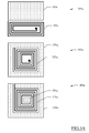
- FIG.3A there are schematically shown different implementations of the metal plate and of the inductor of the resonant LC circuit in top view according to corresponding embodiments of the invention.
- the electronic circuits have a structure being substantially equivalent to that shown in FIG.2B , with the difference that both the metal plate and the inductor (not visible in the figure) are formed on the passivation layer.
- What differentiates the three embodiments represented in FIG.3A is the mutual arrangement of the metal plate and of the inductor (being formed by a winding having a proper number of coils).
- a metal plate 320a 1 and an inductor 325a 1 are put side by side.
- a metal plate 320a 2 is around an inductor 325a 2 (that is, outside its winding).
- a metal plate 320a 3 is both around an inductor 325a 3 and within it; in addition, the metal plate 320a 3 is shaped like a coil of the inductor 325a 3 . In any case, such shaping may be used also for the metal plate 320a 2 of the second embodiment.
- the embodiment of the electronic circuit 305a 1 may be usefully implemented by using standard production processes; therefore, such solution may be used for making electronic devices having reduced costs.
- the embodiments of the electronic devices 305a 2 and 305a 3 may be usefully exploited for avoiding unwanted coupling between neighboring electronic circuits; in fact, the metal plate 320a 2 , 320a 3 around the inductor 325a 2 , 325a 3 causes an effect of segregation of its magnetic field.
- the embodiment of the electronic circuit 305a 3 takes full advantage of the available area, so as to obtain capacitors with higher capacity for the same area occupation, or to reduce the area occupation for the same capacity (thanks to the portion of the metal plate 320a 3 within the inductor 325a 3.
- FIG.3B there is schematically shown the electronic circuit in cross-section (indicated by the reference 305b) with an implementation of the metal plate and of the inductor (indicated with the references 320b and 325b, respectively) according to another embodiment of the present invention.
- the electronic circuit 305b having substantially the same structure as that shown in FIG.2B , has the metal plate 320b being formed on a passivation layer 307; such metal plate 320b is connected to a pad 310 being connected to an inductor 325b, which is formed within the functional substrate 306 being located above the semiconductor substrate 315.
- the inductor 325b affects the size of the electronic circuit 305b, but this may be reduced by increasing the value of the inductance of the inductor 325b by using, for example, magnetic vias 330b within a winding forming the inductor 325b.
- FIG.4A schematically shows an electronic system 400a according to another embodiment of the invention.
- the electronic system 400a includes the above-described electronic circuit 105a (see FIG.1A ) and another electronic circuit 405a having substantially the same structure (whose components are indicated with the same references but replacing the first digit 1 with the digit 4).
- the metal plates 120a and 420a of the electronic circuits 105a and 405a, respectively, are arranged in parallel facing to each other, as well as the respective inductors 125a and 425a.
- the signal transmission between the two electronic circuits 105a and 405a may occur through the resonant channel being created by the virtual short circuit that is created between the two metal plates 120a and 420a and, at the same time, through the magnetic coupling that, by electromagnetic induction, exists between the inductors 125a and 425a.
- FIG.4B schematically shows an electronic system 400b according to a further embodiment of the invention.
- the electronic system 400b includes the above-described electronic circuits 105a and 105a' and a further electronic circuit 405b.
- the electronic circuit 405b includes, as above, a functional region 408b, a transceiver 410b, and terminals 403b, 404b, with the difference that in an area 430 outside the functional region 408b there is formed an inductor 425b (instead of a metal plate) being coupled between the terminals 403b and 404b of the transceiver 410b.
- the electronic circuit 105a may transmit signals simultaneously to the electronic circuit 105a' (by capacitive transmission through the resonant channel between the respective metal plates 120a and 120a') and to the electronic circuit 405b (by inductive transmission because of electromagnetic induction between the respective inductors 125a and 425b), and vice-versa.
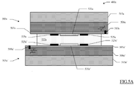
- each electronic circuit 505a, 505a' includes a semiconductor substrate 515a, 515a' on which a functional substrate 506a, 506a' is placed; on the functional substrate 506a, 506a' there is deposited a passivation layer 507a, 507a' in which a pad 510, 510' is formed.
- each electronic circuit 505a, 505a' there are formed a metal plate 520a, 520a' and an inductor 525a, 525a' around it.
- the electronic circuits 505a, 505a' are placed in face-to-face configuration, in which the metal plate 520a and the inductor 525a of the electronic circuit 505a are arranged frontally and parallel to the metal plate 520a' and to the inductor 525a' of the electronic circuit 505a', respectively.
- the area included between the passivation layers 507a and 507a' of the electronic circuits 505a and 505a' is filled with dielectric material 522a for increasing the capacitive coupling.
- the pads 510a of the electronic circuit 510a and the pads 510a' of the electronic circuit 505a' may be connected to external circuits or to each other by using wires (wire bonds in jargon) or contact bumps.
- the electronic circuit 505a and the electronic circuit 505a' in a configuration known as face-to-back (not shown in the figure), which differs from the face-to-face configuration because in one of the two electronic circuits the capacitive plate and the inductor are made under the semiconductor substrate.
- face-to-back not shown in the figure
- TSV Through Silicon Via
- the metal plate may be present above the passivation layer and the inductor may be present under the semiconductor substrate (or vice-versa), and they may be connected to each other through TSVs. Possibly, one of the surfaces of the TSV itself may be used as a capacitor plate.
- FIG.5B there is schematically shown an implementation of the electronic system 400a according to another embodiment of the present invention.
- two electronic circuits 505b, 505b' are implemented in insulated areas of a common functional substrate 506b, being arranged on a semiconductor substrate 515b and being covered by a passivation layer 507b.
- Each electronic circuit 505b, 505b' includes a metal plate 520b, 520b' and an inductor 525b, 525b' that are made within the functional substrate 506b.
- the electronic circuits 505b, 505b' may be separated galvanically to each other but remaining capable of communicating between them.
- the described solution is advantageous since it does not require the assembly of two different electronic circuits and it does not require any further layer of dielectric material; in fact, it is possible to use at least one oxide layer being already present in the functional substrate 506b, which act as insulator between the metal plates 520b, 520b' and the inductors 525b and 525b'.
- the second metal plate is formed by distinct metal plates, each one being coupled with different electronic circuits or different functional blocks of a same electronic circuit.
- each resonant channel will turn out to be active in correspondence to a signal having the specific resonance frequency for the given channel.
- variable inductors and/or capacitors are used for properly modifying the resonance frequencies, for example, for compensating any fluctuations in the resonant frequencies being due to parasitic effects or production imperfections.
- proper circuits some of which may be, for example, gyrators (possibly similar to the Antoniou circuit), may be used for emulating a variable inductance, such as being capable of maximizing the system performance according to at least one electrical parameter being measured by such circuits.
- suitable circuits for example, a programmable frequency oscillator
- a programmable frequency oscillator may be used for varying the frequency according to the resonant circuit and the imperfections thereof, thereby allowing maximizing the transmitted power through proper adaptive algorithms being applied by control circuits that measure at least one parameter of the transmitted and received signal.
- the generic inductor may be replaced by a proper transmission line whose effect and functionality are however equivalent thereto.
- metal plates have shapes being optimized as a function of their area occupation, such as, for example, rhomboidal ones, or if the metal plates are not plane and parallel, but, for example, coaxial cylindrical or concentric spherical ones.
- ferromagnetic properties for example, magnetic permeability greater than 10
- the dielectric layer between the first metal plate and the second metal plate is not present, for example, by exploiting a fluid (for example, the air) being interposed between the two plates as dielectric.
- the conductive particles are not within the layer of dielectric material but in the passivation layer (for example, in case that, in order to reduce the area occupation, there becomes necessary to remove the layer of dielectric material and to use the existing passivation layer as dielectric).
- first capacitive plate and the second capacitive plate have a more complex profile, such as sawtooth-like.
- such a transmission may be implemented in different ways according to corresponding specific requirements.
- the signal can spread over a frequency range around the resonance frequency; in this way, each frequency of the range can be properly used for a corresponding transmission, as a sort of "dedicated communication channel".
- the frequencies of the alternated signals may be equal to each other (and equal to the resonance frequency) or different to each other (but however within a proper frequency range around the resonance frequency for avoiding any excessive loss of intensity of the transmitted signal).
- the proposed structure might be part of the design of an integrated circuit.
- the design may also be created in a programming language; moreover, if the designer does not fabricate chips or masks, the design may be transmitted by physical means to others.
- the resulting integrated circuit may be distributed by its manufacturer in raw wafer form, as a bare die, or in packages.
- the proposed solution may be integrated with other circuits in the same chip, or it may be implemented in intermediate products, such as PCBs (Printed Circuit Boards) or on a generic substrate (for example, of the ceramic type), and coupled with one or more other chips (such as a processor or a memory).
- the integrated circuit is suitable to be used in complex systems (such as computers).
- the metal plate and/or the inductor may also be made outside the integrated circuit ⁇ for example, on a PCB or on a generic substrate (for example, of the ceramic type), together with the possible dielectric layer either including or not metal particles.
- this may be useful for creating interfaces for the test of the described electronic circuits.
- the proposed structure may be part of the design of an integrated system.
- the design may also be created in a programming language; moreover, if the designer does not manufacture the electronic system or the masks, the design may be transmitted by physical means to others.
- the resulting integrated system may be distributed by its manufacturer in raw wafer form, as a bare die, or in packages.
- the proposed structure may be integrated with other circuits and in the same chip, or it may be mounted in intermediate products (such as mother boards) and coupled with one or more other chips (such as a processor).
- the integrated system is suitable to be used in complex systems (such as automotive applications or microcontrollers).
- the solution according to an embodiment of the invention lends itself to be implemented through an equivalent method (by using similar steps, removing some steps being not essential, or adding further optional steps); moreover, the steps may be performed in different order, concurrently or in an interleaved way (at least partly).
Landscapes
- Engineering & Computer Science (AREA)
- Computer Networks & Wireless Communication (AREA)
- Signal Processing (AREA)
- Power Engineering (AREA)
- Physics & Mathematics (AREA)
- Electromagnetism (AREA)
- Semiconductor Integrated Circuits (AREA)
Applications Claiming Priority (1)
| Application Number | Priority Date | Filing Date | Title |
|---|---|---|---|
| ITMI20091825 | 2009-10-21 |
Publications (2)
| Publication Number | Publication Date |
|---|---|
| EP2315364A1 true EP2315364A1 (fr) | 2011-04-27 |
| EP2315364B1 EP2315364B1 (fr) | 2016-12-07 |
Family
ID=42138737
Family Applications (1)
| Application Number | Title | Priority Date | Filing Date |
|---|---|---|---|
| EP10188100.1A Active EP2315364B1 (fr) | 2009-10-21 | 2010-10-19 | Transmission de signal par circuits résonants LC |
Country Status (2)
| Country | Link |
|---|---|
| US (2) | US8902016B2 (fr) |
| EP (1) | EP2315364B1 (fr) |
Families Citing this family (31)
| Publication number | Priority date | Publication date | Assignee | Title |
|---|---|---|---|---|
| US20110006443A1 (en) * | 2008-03-13 | 2011-01-13 | Nec Corporation | Semiconductor device |
| US8791711B2 (en) | 2009-10-21 | 2014-07-29 | Stmicroelectronics S.R.L. | Testing of electronic devices through capacitive interface |
| US8902016B2 (en) * | 2009-10-21 | 2014-12-02 | Stmicroelectronics S.R.L. | Signal transmission through LC resonant circuits |
| US9054745B2 (en) * | 2010-12-22 | 2015-06-09 | Electronics And Telecommunications Research Institute | Apparatus for transmitting/receiving energy using a resonance structure in an energy system |
| US9614590B2 (en) | 2011-05-12 | 2017-04-04 | Keyssa, Inc. | Scalable high-bandwidth connectivity |
| WO2013024417A2 (fr) * | 2011-08-16 | 2013-02-21 | Koninklijke Philips Electronics N.V. | Couche conductrice dotée d'une large surface permettant de répartir l'énergie à l'aide d'un transfert d'énergie capacitive |
| CN103875161B (zh) * | 2011-08-16 | 2017-02-15 | 皇家飞利浦有限公司 | 被利用作为电容性电力输送系统的无线电力转换器 |
| WO2013024404A2 (fr) * | 2011-08-16 | 2013-02-21 | Koninklijke Philips Electronics N.V. | Couche conductrice dotée d'une large surface permettant de répartir l'énergie à l'aide d'un transfert d'énergie capacitive |
| EP2754221B1 (fr) | 2011-09-07 | 2019-01-23 | Solace Power Inc. | Système et procédé de transmission sans fil de puissance de champ électrique |
| JP5844472B2 (ja) | 2011-09-15 | 2016-01-20 | ケッサ・インコーポレーテッド | 誘電媒体による無線通信 |
| KR101995608B1 (ko) | 2011-10-20 | 2019-10-17 | 키사, 아이엔씨. | 저-프로파일 무선 커넥터들 |
| US9559790B2 (en) | 2012-01-30 | 2017-01-31 | Keyssa, Inc. | Link emission control |
| US9344201B2 (en) | 2012-01-30 | 2016-05-17 | Keyssa, Inc. | Shielded EHF connector assemblies |
| US9007141B2 (en) * | 2012-05-23 | 2015-04-14 | Nxp B.V. | Interface for communication between voltage domains |
| SG195415A1 (en) * | 2012-05-28 | 2013-12-30 | Sony Corp | A coupler |
| JP5980329B2 (ja) * | 2012-07-02 | 2016-08-31 | 富士機械製造株式会社 | 静電結合方式非接触給電装置 |
| US20160322867A1 (en) * | 2012-09-07 | 2016-11-03 | Nagesh POLU | Wireless electric/magnetic field power transfer system, transmitter and receiver |
| EP2782262B1 (fr) * | 2013-03-19 | 2015-05-06 | Tyco Electronics Nederland B.V. | Coupleur sans contact pour la transmission de signaux couplés de manière capacitive |
| JP2014220889A (ja) * | 2013-05-07 | 2014-11-20 | 昭和電工株式会社 | ワイヤレス給電方法及びワイヤレス給電システム |
| US9923380B2 (en) * | 2014-03-07 | 2018-03-20 | Intel Corporation | Capacitive element coupling in wireless power |
| JP2017520231A (ja) * | 2014-06-26 | 2017-07-20 | ソレース・パワー・インコーポレイテッド | ワイヤレス電場電力伝送システム、そのための送信器及び受信器、並びにワイヤレスに電力を伝送するための方法 |
| CN111509868B (zh) | 2014-09-05 | 2023-11-24 | 索雷斯能源公司 | 无线电力传递系统及其车辆 |
| US9960671B2 (en) * | 2014-12-31 | 2018-05-01 | Avago Technologies General Ip (Singapore) Pte. Ltd. | Isolator with reduced susceptibility to parasitic coupling |
| US10483254B2 (en) * | 2017-01-17 | 2019-11-19 | Advanced Semiconductor Engineering, Inc. | Electronic module and semiconductor package device |
| US10074939B1 (en) * | 2017-08-08 | 2018-09-11 | Allegro Microsystems, Llc | Signal isolator having inductive and capacitive signal coupling |
| CN108494102B (zh) * | 2018-04-19 | 2021-11-02 | 西南交通大学 | 一种具有高抗偏移性的电场耦合式无线电能传输拓扑结构 |
| US20200204212A1 (en) * | 2018-12-20 | 2020-06-25 | Arris Enterprises Llc | Last meter wireless broadband |
| US11342288B2 (en) | 2019-06-04 | 2022-05-24 | Allegro Microsystems, Llc | Signal isolator having at least one isolation island |
| US11029366B2 (en) | 2019-08-13 | 2021-06-08 | Allegro Microsystems, Llc | Ground disconnect detection for multiple voltage domains |
| CN111355309B (zh) * | 2020-03-12 | 2022-04-22 | 宁波大学 | 一种基于硅通孔电感器的无线功率传输电路 |
| US11515246B2 (en) | 2020-10-09 | 2022-11-29 | Allegro Microsystems, Llc | Dual circuit digital isolator |
Citations (4)
| Publication number | Priority date | Publication date | Assignee | Title |
|---|---|---|---|---|
| US5625883A (en) * | 1993-12-24 | 1997-04-29 | U.S. Philips Corporation | System for wireless information transmission between two different rooms |
| US20090073070A1 (en) * | 2007-03-30 | 2009-03-19 | Broadcom Corporation | Dual band antenna and methods for use therewith |
| US20090085696A1 (en) * | 2007-09-28 | 2009-04-02 | Motorola, Inc. | Method and apparatus for rf signal transmission in a slider phone |
| EP2086052A1 (fr) * | 2007-07-18 | 2009-08-05 | Murata Manufacturing Co. Ltd. | Dispositif à circuit intégré sans fil |
Family Cites Families (28)
| Publication number | Priority date | Publication date | Assignee | Title |
|---|---|---|---|---|
| FI84536C (fi) * | 1989-05-22 | 1991-12-10 | Nokia Mobira Oy | Rf-anslutningsdon foer anslutning av en radiotelefon till en yttre antenn. |
| US5072176A (en) | 1990-07-10 | 1991-12-10 | The United States Of America As Represented By The Secretary Of The Army | Flexible membrane circuit tester |
| US5302557A (en) * | 1991-12-03 | 1994-04-12 | E. I. Du Pont De Nemours And Company | Automotive glass thick film conductor paste |
| US5444600A (en) * | 1992-12-03 | 1995-08-22 | Linear Technology Corporation | Lead frame capacitor and capacitively-coupled isolator circuit using the same |
| TW225047B (en) * | 1992-12-16 | 1994-06-11 | Daiichi Denpa Kogyo Kk | A linkup device and a antenna device of a co-axial cable |
| US5451966A (en) * | 1994-09-23 | 1995-09-19 | The Antenna Company | Ultra-high frequency, slot coupled, low-cost antenna system |
| US6359973B1 (en) * | 1998-11-16 | 2002-03-19 | Conexant Systems, Inc. | Data access arrangement utilizing a serialized digital data path across an isolation barrier |
| US6538609B2 (en) * | 1999-11-10 | 2003-03-25 | Xm Satellite Radio Inc. | Glass-mountable antenna system with DC and RF coupling |
| US6686882B2 (en) * | 2000-10-19 | 2004-02-03 | Xm Satellite Radio, Inc. | Apparatus and method for transferring DC power and RF energy through a dielectric for antenna reception |
| US7143500B2 (en) | 2001-06-25 | 2006-12-05 | Micron Technology, Inc. | Method to prevent damage to probe card |
| US20030107387A1 (en) | 2001-12-06 | 2003-06-12 | Scott Williams | Multi-beam probe card |
| US6947853B2 (en) | 2002-05-23 | 2005-09-20 | Oht, Inc. | Apparatus and method for inspecting electrical continuity of circuit board, jig for use therein, and recording medium thereon |
| CN100390554C (zh) | 2002-09-13 | 2008-05-28 | Nxp股份有限公司 | 在晶片级减少的芯片测试方案 |
| US6930494B2 (en) | 2003-08-29 | 2005-08-16 | Agilent Technologies, Inc. | Capacitive probe assembly with flex circuit |
| US8581610B2 (en) | 2004-04-21 | 2013-11-12 | Charles A Miller | Method of designing an application specific probe card test system |
| US7302247B2 (en) * | 2004-06-03 | 2007-11-27 | Silicon Laboratories Inc. | Spread spectrum isolator |
| US7737871B2 (en) * | 2004-06-03 | 2010-06-15 | Silicon Laboratories Inc. | MCU with integrated voltage isolator to provide a galvanic isolation between input and output |
| US7348786B2 (en) | 2004-08-31 | 2008-03-25 | Georgia Tech Research Corporation | Probe module for testing chips with electrical and optical input/output interconnects, methods of use, and methods of fabrication |
| US7046027B2 (en) | 2004-10-15 | 2006-05-16 | Teradyne, Inc. | Interface apparatus for semiconductor device tester |
| JP2007165459A (ja) | 2005-12-12 | 2007-06-28 | Mitsubishi Electric Corp | マルチチップモジュール |
| US7345492B2 (en) | 2005-12-14 | 2008-03-18 | Microprobe, Inc. | Probe cards employing probes having retaining portions for potting in a retention arrangement |
| US7952375B2 (en) | 2006-06-06 | 2011-05-31 | Formfactor, Inc. | AC coupled parameteric test probe |
| JP2008021848A (ja) | 2006-07-13 | 2008-01-31 | Sharp Corp | ウェハおよび半導体装置のテスト方法 |
| TW200907347A (en) | 2007-08-07 | 2009-02-16 | Chunghwa Prec Test Tech Co Ltd | Structure of test carrier board with fine pitch and manufacturing method thereof |
| US7919909B2 (en) * | 2009-04-24 | 2011-04-05 | Delaware Capital Formation, Inc. | Integrated coupling structures |
| US8902016B2 (en) * | 2009-10-21 | 2014-12-02 | Stmicroelectronics S.R.L. | Signal transmission through LC resonant circuits |
| US8791711B2 (en) | 2009-10-21 | 2014-07-29 | Stmicroelectronics S.R.L. | Testing of electronic devices through capacitive interface |
| US9229031B2 (en) | 2010-05-12 | 2016-01-05 | Stmicroelectronics S.R.L. | Probes for testing integrated electronic circuits and corresponding production method |
-
2010
- 2010-10-19 US US12/907,812 patent/US8902016B2/en active Active
- 2010-10-19 EP EP10188100.1A patent/EP2315364B1/fr active Active
-
2014
- 2014-09-05 US US14/479,089 patent/US9514879B2/en active Active
Patent Citations (4)
| Publication number | Priority date | Publication date | Assignee | Title |
|---|---|---|---|---|
| US5625883A (en) * | 1993-12-24 | 1997-04-29 | U.S. Philips Corporation | System for wireless information transmission between two different rooms |
| US20090073070A1 (en) * | 2007-03-30 | 2009-03-19 | Broadcom Corporation | Dual band antenna and methods for use therewith |
| EP2086052A1 (fr) * | 2007-07-18 | 2009-08-05 | Murata Manufacturing Co. Ltd. | Dispositif à circuit intégré sans fil |
| US20090085696A1 (en) * | 2007-09-28 | 2009-04-02 | Motorola, Inc. | Method and apparatus for rf signal transmission in a slider phone |
Also Published As
| Publication number | Publication date |
|---|---|
| US20140375398A1 (en) | 2014-12-25 |
| US20110090030A1 (en) | 2011-04-21 |
| EP2315364B1 (fr) | 2016-12-07 |
| US8902016B2 (en) | 2014-12-02 |
| US9514879B2 (en) | 2016-12-06 |
Similar Documents
| Publication | Publication Date | Title |
|---|---|---|
| EP2315364B1 (fr) | Transmission de signal par circuits résonants LC | |
| EP2319078B1 (fr) | Transformateur à fort facteur q installé au moins en partie dans un substrat non semi-conducteur | |
| EP2940700B1 (fr) | Inducteurs tridimensionnels (3d) à noyau magnétique et intégration d'emballage | |
| US6800936B2 (en) | High-frequency module device | |
| US8704627B2 (en) | Inductor element, integrated circuit device, and three-dimensional circuit device | |
| US8400307B2 (en) | Radio frequency IC device and electronic apparatus | |
| US10535909B2 (en) | Methods of forming flipped RF filter components | |
| US7280024B2 (en) | Integrated transformer structure and method of fabrication | |
| US7525812B2 (en) | Chip carrier and fabrication method | |
| US8791544B2 (en) | Semiconductor device, mounted substrate to be used in semiconductor device, and manufacturing method of mounted substrate | |
| US9596750B2 (en) | Electronic circuit, method of manufacturing electronic circuit, and mounting member | |
| KR20040080921A (ko) | 회로 기판 장치 및 그 제조 방법 | |
| WO2006065539A2 (fr) | Carte de circuit imprime multi-couche comprenant une connexion traversante pour applications haute frequence | |
| TWI649841B (zh) | High frequency module and manufacturing method thereof | |
| US20130277803A1 (en) | Connection structure for an integrated circuit with capacitive function | |
| US9064631B2 (en) | Through-chip interface (TCI) structure for wireless chip-to-chip communication | |
| JP4291164B2 (ja) | 弾性表面波装置 | |
| CN111564426A (zh) | 射频前端模组、射频通信装置和电子设备 | |
| CN106532212A (zh) | 一种基于陶瓷微带线的射频垂直过渡结构 | |
| EP2860757B1 (fr) | Circuit intégré | |
| KR20080092278A (ko) | 안테나 소자 및 반도체 장치 | |
| CN115458511B (zh) | 一种滤波器电路封装结构及其制作方法 | |
| TW200403885A (en) | Semiconductor module structure incorporating antenna | |
| JP2008263360A (ja) | 高周波基板装置 | |
| WO2021079782A1 (fr) | Dispositif isolé de transmission |
Legal Events
| Date | Code | Title | Description |
|---|---|---|---|
| PUAI | Public reference made under article 153(3) epc to a published international application that has entered the european phase |
Free format text: ORIGINAL CODE: 0009012 |
|
| AK | Designated contracting states |
Kind code of ref document: A1 Designated state(s): AL AT BE BG CH CY CZ DE DK EE ES FI FR GB GR HR HU IE IS IT LI LT LU LV MC MK MT NL NO PL PT RO RS SE SI SK SM TR |
|
| AX | Request for extension of the european patent |
Extension state: BA ME |
|
| 17P | Request for examination filed |
Effective date: 20111026 |
|
| RAP1 | Party data changed (applicant data changed or rights of an application transferred) |
Owner name: STMICROELECTRONICS SRL |
|
| 17Q | First examination report despatched |
Effective date: 20150327 |
|
| REG | Reference to a national code |
Ref country code: DE Ref legal event code: R079 Ref document number: 602010038584 Country of ref document: DE Free format text: PREVIOUS MAIN CLASS: H04B0005000000 Ipc: H01F0038140000 |
|
| GRAP | Despatch of communication of intention to grant a patent |
Free format text: ORIGINAL CODE: EPIDOSNIGR1 |
|
| RIC1 | Information provided on ipc code assigned before grant |
Ipc: H01F 38/14 20060101AFI20160427BHEP Ipc: H04B 5/00 20060101ALI20160427BHEP |
|
| INTG | Intention to grant announced |
Effective date: 20160530 |
|
| GRAS | Grant fee paid |
Free format text: ORIGINAL CODE: EPIDOSNIGR3 |
|
| GRAA | (expected) grant |
Free format text: ORIGINAL CODE: 0009210 |
|
| AK | Designated contracting states |
Kind code of ref document: B1 Designated state(s): AL AT BE BG CH CY CZ DE DK EE ES FI FR GB GR HR HU IE IS IT LI LT LU LV MC MK MT NL NO PL PT RO RS SE SI SK SM TR |
|
| REG | Reference to a national code |
Ref country code: GB Ref legal event code: FG4D |
|
| REG | Reference to a national code |
Ref country code: CH Ref legal event code: EP Ref country code: AT Ref legal event code: REF Ref document number: 852370 Country of ref document: AT Kind code of ref document: T Effective date: 20161215 |
|
| REG | Reference to a national code |
Ref country code: IE Ref legal event code: FG4D |
|
| REG | Reference to a national code |
Ref country code: DE Ref legal event code: R096 Ref document number: 602010038584 Country of ref document: DE |
|
| PG25 | Lapsed in a contracting state [announced via postgrant information from national office to epo] |
Ref country code: LV Free format text: LAPSE BECAUSE OF FAILURE TO SUBMIT A TRANSLATION OF THE DESCRIPTION OR TO PAY THE FEE WITHIN THE PRESCRIBED TIME-LIMIT Effective date: 20161207 |
|
| REG | Reference to a national code |
Ref country code: LT Ref legal event code: MG4D |
|
| REG | Reference to a national code |
Ref country code: NL Ref legal event code: MP Effective date: 20161207 |
|
| PG25 | Lapsed in a contracting state [announced via postgrant information from national office to epo] |
Ref country code: NO Free format text: LAPSE BECAUSE OF FAILURE TO SUBMIT A TRANSLATION OF THE DESCRIPTION OR TO PAY THE FEE WITHIN THE PRESCRIBED TIME-LIMIT Effective date: 20170307 Ref country code: GR Free format text: LAPSE BECAUSE OF FAILURE TO SUBMIT A TRANSLATION OF THE DESCRIPTION OR TO PAY THE FEE WITHIN THE PRESCRIBED TIME-LIMIT Effective date: 20170308 Ref country code: LT Free format text: LAPSE BECAUSE OF FAILURE TO SUBMIT A TRANSLATION OF THE DESCRIPTION OR TO PAY THE FEE WITHIN THE PRESCRIBED TIME-LIMIT Effective date: 20161207 Ref country code: SE Free format text: LAPSE BECAUSE OF FAILURE TO SUBMIT A TRANSLATION OF THE DESCRIPTION OR TO PAY THE FEE WITHIN THE PRESCRIBED TIME-LIMIT Effective date: 20161207 |
|
| REG | Reference to a national code |
Ref country code: AT Ref legal event code: MK05 Ref document number: 852370 Country of ref document: AT Kind code of ref document: T Effective date: 20161207 |
|
| PG25 | Lapsed in a contracting state [announced via postgrant information from national office to epo] |
Ref country code: FI Free format text: LAPSE BECAUSE OF FAILURE TO SUBMIT A TRANSLATION OF THE DESCRIPTION OR TO PAY THE FEE WITHIN THE PRESCRIBED TIME-LIMIT Effective date: 20161207 Ref country code: HR Free format text: LAPSE BECAUSE OF FAILURE TO SUBMIT A TRANSLATION OF THE DESCRIPTION OR TO PAY THE FEE WITHIN THE PRESCRIBED TIME-LIMIT Effective date: 20161207 Ref country code: ES Free format text: LAPSE BECAUSE OF FAILURE TO SUBMIT A TRANSLATION OF THE DESCRIPTION OR TO PAY THE FEE WITHIN THE PRESCRIBED TIME-LIMIT Effective date: 20161207 Ref country code: RS Free format text: LAPSE BECAUSE OF FAILURE TO SUBMIT A TRANSLATION OF THE DESCRIPTION OR TO PAY THE FEE WITHIN THE PRESCRIBED TIME-LIMIT Effective date: 20161207 |
|
| PG25 | Lapsed in a contracting state [announced via postgrant information from national office to epo] |
Ref country code: NL Free format text: LAPSE BECAUSE OF FAILURE TO SUBMIT A TRANSLATION OF THE DESCRIPTION OR TO PAY THE FEE WITHIN THE PRESCRIBED TIME-LIMIT Effective date: 20161207 |
|
| PG25 | Lapsed in a contracting state [announced via postgrant information from national office to epo] |
Ref country code: EE Free format text: LAPSE BECAUSE OF FAILURE TO SUBMIT A TRANSLATION OF THE DESCRIPTION OR TO PAY THE FEE WITHIN THE PRESCRIBED TIME-LIMIT Effective date: 20161207 Ref country code: CZ Free format text: LAPSE BECAUSE OF FAILURE TO SUBMIT A TRANSLATION OF THE DESCRIPTION OR TO PAY THE FEE WITHIN THE PRESCRIBED TIME-LIMIT Effective date: 20161207 Ref country code: RO Free format text: LAPSE BECAUSE OF FAILURE TO SUBMIT A TRANSLATION OF THE DESCRIPTION OR TO PAY THE FEE WITHIN THE PRESCRIBED TIME-LIMIT Effective date: 20161207 Ref country code: IS Free format text: LAPSE BECAUSE OF FAILURE TO SUBMIT A TRANSLATION OF THE DESCRIPTION OR TO PAY THE FEE WITHIN THE PRESCRIBED TIME-LIMIT Effective date: 20170407 Ref country code: SK Free format text: LAPSE BECAUSE OF FAILURE TO SUBMIT A TRANSLATION OF THE DESCRIPTION OR TO PAY THE FEE WITHIN THE PRESCRIBED TIME-LIMIT Effective date: 20161207 |
|
| PG25 | Lapsed in a contracting state [announced via postgrant information from national office to epo] |
Ref country code: AT Free format text: LAPSE BECAUSE OF FAILURE TO SUBMIT A TRANSLATION OF THE DESCRIPTION OR TO PAY THE FEE WITHIN THE PRESCRIBED TIME-LIMIT Effective date: 20161207 Ref country code: PL Free format text: LAPSE BECAUSE OF FAILURE TO SUBMIT A TRANSLATION OF THE DESCRIPTION OR TO PAY THE FEE WITHIN THE PRESCRIBED TIME-LIMIT Effective date: 20161207 Ref country code: BG Free format text: LAPSE BECAUSE OF FAILURE TO SUBMIT A TRANSLATION OF THE DESCRIPTION OR TO PAY THE FEE WITHIN THE PRESCRIBED TIME-LIMIT Effective date: 20170307 Ref country code: SM Free format text: LAPSE BECAUSE OF FAILURE TO SUBMIT A TRANSLATION OF THE DESCRIPTION OR TO PAY THE FEE WITHIN THE PRESCRIBED TIME-LIMIT Effective date: 20161207 Ref country code: BE Free format text: LAPSE BECAUSE OF FAILURE TO SUBMIT A TRANSLATION OF THE DESCRIPTION OR TO PAY THE FEE WITHIN THE PRESCRIBED TIME-LIMIT Effective date: 20161207 Ref country code: PT Free format text: LAPSE BECAUSE OF FAILURE TO SUBMIT A TRANSLATION OF THE DESCRIPTION OR TO PAY THE FEE WITHIN THE PRESCRIBED TIME-LIMIT Effective date: 20170407 Ref country code: IT Free format text: LAPSE BECAUSE OF FAILURE TO SUBMIT A TRANSLATION OF THE DESCRIPTION OR TO PAY THE FEE WITHIN THE PRESCRIBED TIME-LIMIT Effective date: 20161207 |
|
| REG | Reference to a national code |
Ref country code: DE Ref legal event code: R097 Ref document number: 602010038584 Country of ref document: DE |
|
| PLBE | No opposition filed within time limit |
Free format text: ORIGINAL CODE: 0009261 |
|
| STAA | Information on the status of an ep patent application or granted ep patent |
Free format text: STATUS: NO OPPOSITION FILED WITHIN TIME LIMIT |
|
| 26N | No opposition filed |
Effective date: 20170908 |
|
| PG25 | Lapsed in a contracting state [announced via postgrant information from national office to epo] |
Ref country code: DK Free format text: LAPSE BECAUSE OF FAILURE TO SUBMIT A TRANSLATION OF THE DESCRIPTION OR TO PAY THE FEE WITHIN THE PRESCRIBED TIME-LIMIT Effective date: 20161207 Ref country code: SI Free format text: LAPSE BECAUSE OF FAILURE TO SUBMIT A TRANSLATION OF THE DESCRIPTION OR TO PAY THE FEE WITHIN THE PRESCRIBED TIME-LIMIT Effective date: 20161207 |
|
| PG25 | Lapsed in a contracting state [announced via postgrant information from national office to epo] |
Ref country code: MC Free format text: LAPSE BECAUSE OF FAILURE TO SUBMIT A TRANSLATION OF THE DESCRIPTION OR TO PAY THE FEE WITHIN THE PRESCRIBED TIME-LIMIT Effective date: 20161207 |
|
| REG | Reference to a national code |
Ref country code: CH Ref legal event code: PL |
|
| GBPC | Gb: european patent ceased through non-payment of renewal fee |
Effective date: 20171019 |
|
| REG | Reference to a national code |
Ref country code: IE Ref legal event code: MM4A |
|
| REG | Reference to a national code |
Ref country code: FR Ref legal event code: ST Effective date: 20180629 |
|
| PG25 | Lapsed in a contracting state [announced via postgrant information from national office to epo] |
Ref country code: GB Free format text: LAPSE BECAUSE OF NON-PAYMENT OF DUE FEES Effective date: 20171019 Ref country code: CH Free format text: LAPSE BECAUSE OF NON-PAYMENT OF DUE FEES Effective date: 20171031 Ref country code: LI Free format text: LAPSE BECAUSE OF NON-PAYMENT OF DUE FEES Effective date: 20171031 Ref country code: LU Free format text: LAPSE BECAUSE OF NON-PAYMENT OF DUE FEES Effective date: 20171019 |
|
| PG25 | Lapsed in a contracting state [announced via postgrant information from national office to epo] |
Ref country code: FR Free format text: LAPSE BECAUSE OF NON-PAYMENT OF DUE FEES Effective date: 20171031 |
|
| PG25 | Lapsed in a contracting state [announced via postgrant information from national office to epo] |
Ref country code: MT Free format text: LAPSE BECAUSE OF NON-PAYMENT OF DUE FEES Effective date: 20171019 |
|
| PG25 | Lapsed in a contracting state [announced via postgrant information from national office to epo] |
Ref country code: IE Free format text: LAPSE BECAUSE OF NON-PAYMENT OF DUE FEES Effective date: 20171019 |
|
| PG25 | Lapsed in a contracting state [announced via postgrant information from national office to epo] |
Ref country code: HU Free format text: LAPSE BECAUSE OF FAILURE TO SUBMIT A TRANSLATION OF THE DESCRIPTION OR TO PAY THE FEE WITHIN THE PRESCRIBED TIME-LIMIT; INVALID AB INITIO Effective date: 20101019 |
|
| PG25 | Lapsed in a contracting state [announced via postgrant information from national office to epo] |
Ref country code: CY Free format text: LAPSE BECAUSE OF NON-PAYMENT OF DUE FEES Effective date: 20161207 |
|
| PG25 | Lapsed in a contracting state [announced via postgrant information from national office to epo] |
Ref country code: MK Free format text: LAPSE BECAUSE OF FAILURE TO SUBMIT A TRANSLATION OF THE DESCRIPTION OR TO PAY THE FEE WITHIN THE PRESCRIBED TIME-LIMIT Effective date: 20161207 |
|
| PG25 | Lapsed in a contracting state [announced via postgrant information from national office to epo] |
Ref country code: TR Free format text: LAPSE BECAUSE OF FAILURE TO SUBMIT A TRANSLATION OF THE DESCRIPTION OR TO PAY THE FEE WITHIN THE PRESCRIBED TIME-LIMIT Effective date: 20161207 |
|
| PG25 | Lapsed in a contracting state [announced via postgrant information from national office to epo] |
Ref country code: AL Free format text: LAPSE BECAUSE OF FAILURE TO SUBMIT A TRANSLATION OF THE DESCRIPTION OR TO PAY THE FEE WITHIN THE PRESCRIBED TIME-LIMIT Effective date: 20161207 |
|
| PGFP | Annual fee paid to national office [announced via postgrant information from national office to epo] |
Ref country code: DE Payment date: 20230920 Year of fee payment: 14 |