EP2315327A2 - Unterputz-Elektro-Installationsgerät mit Spreizen - Google Patents
Unterputz-Elektro-Installationsgerät mit Spreizen Download PDFInfo
- Publication number
- EP2315327A2 EP2315327A2 EP10186390A EP10186390A EP2315327A2 EP 2315327 A2 EP2315327 A2 EP 2315327A2 EP 10186390 A EP10186390 A EP 10186390A EP 10186390 A EP10186390 A EP 10186390A EP 2315327 A2 EP2315327 A2 EP 2315327A2
- Authority
- EP
- European Patent Office
- Prior art keywords
- spreader
- flush
- installation device
- electrical installation
- legs
- Prior art date
- Legal status (The legal status is an assumption and is not a legal conclusion. Google has not performed a legal analysis and makes no representation as to the accuracy of the status listed.)
- Granted
Links
Images

Classifications
-
- H—ELECTRICITY
- H02—GENERATION; CONVERSION OR DISTRIBUTION OF ELECTRIC POWER
- H02G—INSTALLATION OF ELECTRIC CABLES OR LINES, OR OF COMBINED OPTICAL AND ELECTRIC CABLES OR LINES
- H02G3/00—Installations of electric cables or lines or protective tubing therefor in or on buildings, equivalent structures or vehicles
- H02G3/02—Details
- H02G3/08—Distribution boxes; Connection or junction boxes
- H02G3/12—Distribution boxes; Connection or junction boxes for flush mounting
- H02G3/121—Distribution boxes; Connection or junction boxes for flush mounting in plain walls
-
- H—ELECTRICITY
- H02—GENERATION; CONVERSION OR DISTRIBUTION OF ELECTRIC POWER
- H02G—INSTALLATION OF ELECTRIC CABLES OR LINES, OR OF COMBINED OPTICAL AND ELECTRIC CABLES OR LINES
- H02G3/00—Installations of electric cables or lines or protective tubing therefor in or on buildings, equivalent structures or vehicles
- H02G3/02—Details
- H02G3/08—Distribution boxes; Connection or junction boxes
- H02G3/18—Distribution boxes; Connection or junction boxes providing line outlets
Definitions
- the invention relates to a flush-mounted electrical installation device with a support plate for receiving an insert, wherein the support plate has spreader holders for holding / storing two opposing struts and can, for. B. for flush-mounted sockets, flush-mounted switches, flush-mounted buttons, flush-mounted dimmers, etc. application.
- a flush-mounted electrical installation device such as the socket base of a power outlet is usually from a support plate made of metal, z. B. a support ring, added.
- the spreader claw is usually stored and held on the carrier plate using a spreader holder.
- Fig. 6 this is a perspective view of the front of a support plate made of metal (support ring) 2 with two opposite, held in Spreizenhalterungen 3 / stored conventional expanding claws 4 shown.
- the spreading claws 4 are pressed with the aid of leaf springs 5 in a rest position in the direction of the insert (eg socket base), in which a removal of the flush-mounted electrical installation device from the flush-mounted box is possible in a simple manner.
- the invention has for its object to provide an optimized in terms of electrical safety flush-mounted electrical installation device with struts.
- a spreader is formed of an electrically insulating plastic, consisting of a base plate with two rectangular legs formed thereon, wherein the base plate enclosed by a peripheral reinforcing bead recess for Carrying out an adjusting screw.
- the spreader legs of the spreader can each have a claw with outward facing toothing.
- a spreader in plastic-metal hybrid structure may be used, in which the spreader legs of the spreader each have a widened claw with pickled or umspritztem outwardly directed metal pin.
- a spreader with attached metal component can be used, consisting of a metal bracket with a base leg and two perpendicularly formed thereon, around the spreader leg engaging side legs, said metal bracket having at least one outwardly directed tip.
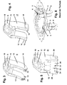
- Fig. 1 is a perspective view of the back of an insert of a flush-mounted electrical installation device shown. It is an insert 1, z. B. a switch socket, with support plate 2 (support ring) to recognize, which is provided with two spreader holders 3, which serve for holding / storing each spreader 17. Details of the struts 17 are below Fig. 4 explained.
- FIG. 2 is a perspective view of the front of a carrier plate with spars shown. There are the two arranged on the support plate 2, opposite spreader holders 3 can be seen, each holding a spreader 17 / store. Furthermore, the two screws 6 are outlined.
- Fig. 3 is shown a perspective view of a plastic strut.
- the spreader 8 is formed from an electrically insulating plastic and consists of a base plate 9 with two right angles formed thereon spreader legs 12, 13, wherein the base plate 9 has a peripheral edge of a reinforcing bead 11 enclosed recess 10 for carrying out a set screw 6. It is a high-strength plastic used.
- the spreader legs 12, 13 of the spreader 8 each have a claw 14 with outwardly directed, ie directed towards the wall of the UP device box gear teeth 15 in the case of installation.
- z. B. corresponds to the requirements placed on switches and dimmers in terms of pull-out force from the flush-mounted box.
- Fig. 4 is shown a perspective view of a spreader in plastic-metal hybrid structure.
- the embodiment with base plate 9, recess 10, reinforcing bead 11 and spreading legs 12, 13 made of high-strength plastic is as explained above.
- the spreader legs 12, 13 each end a widened claw 18 with inlaid or partially encapsulated (insert technology using plastic injection molding), outwardly directed metal pin 19.
- a toothing between metal and plastic is provided to ensure a permanent connection, for. B. in the form of ribs on the metal pin 19 or recesses in the metal pin 19.
- the metal pin 19 has a tip, which of course is free of plastic material.
- Fig. 5 is a perspective view of a plastic spreader with attached metal component shown.
- the embodiment with base plate 9, recess 10, reinforcing bead 11 and spreading legs 12, 13 made of high-strength plastic is as explained above.
- a metal component is fastened to the spreader 21 shown, consisting of a metal strap 22 with a base leg 23 and two side legs 25, 26 formed at right angles thereto, around the spreader legs 12, 13.
- the metal strap 22 has at least one (two in the example shown) outwardly directed tip 24.
- FIGS. 4 and 5 correspond to increased requirements regarding the pull-out force from the flush-mounted box.
Landscapes
- Engineering & Computer Science (AREA)
- Architecture (AREA)
- Civil Engineering (AREA)
- Structural Engineering (AREA)
- Clamps And Clips (AREA)
- Details Of Indoor Wiring (AREA)
- Installation Of Indoor Wiring (AREA)
- Connector Housings Or Holding Contact Members (AREA)
- Switch Cases, Indication, And Locking (AREA)
- Elevator Control (AREA)
- Casings For Electric Apparatus (AREA)
Abstract
Description
- Die Erfindung betrifft ein Unterputz-Elektro-Installationsgerät mit einer Trägerplatte für die Aufnahme eines Einsatzes, wobei die Trägerplatte Spreizenhalterungen zum Halten / Lagern von zwei sich gegenüberliegenden Spreizen aufweist und kann z. B. bei Unterputz-Steckdosen, Unterputz-Schaltern, Unterputz-Tastern, Unterputz-Dimmern usw. Anwendung finden.
- Aus der
EP 0 349 937 B1 ist ein elektrisches Installationsgerät bekannt, welches mit Hilfe einer Spreizkrallenbefestigung in einer Unterputz-Wandeinbaudose montierbar ist, mit einem Tragring sowie zwei an diesem paarig gegenüberliegend angeordneten, jeweils von einer Blattfeder beaufschlagten Spreizkrallen, deren erster Spreizkrallenschenkel mittels einer Stellschraube an Teilen des Tragrings befestigt ist und deren zweiter Spreizkrallenschenkel unter einem Spreizkrallenknickwinkel gegenüber dem ersten Spreizkrallenschenkel abgewinkelt ist, wobei der zweite Spreizkrallenschenkel und ein zweiter Blattfederschenkel parallel ausgerichtet sind. Auf dem zweiten Spreizkrallenschenkel ist das freie Ende des zweiten Blattfederschenkels der federeleastischen Blattfeder befestigt, wobei der zweite Blattfederschenkel gegenüber einem ersten Blattfederschenkel der Blattfeder unter einem Blattfederknickwinkel abgewinkelt ist. Am freien Ende des ersten Blattfederschenkels ist ein auf Teilen des Tragrings aufliegendes und sich dort unter Vorspannung abstützendes Gleitbogenstück ausgebildet. - Der Einsatz eines Unterputz-Elektro-Installationsgerätes, wie z. B. der Steckdosensockel einer Steckdose, wird in der Regel von einer Trägerplatte aus Metall, z. B. einem Tragring, aufgenommen. Die Spreizkralle wird dabei üblicherweise unter Verwendung einer Spreizenhalterung an der Trägerplatte gelagert und gehalten. In
Fig. 6 (Stand der Technik) ist hierzu eine perspektivische Sicht auf die Vorderseite einer Trägerplatte aus Metall (Tragring) 2 mit zwei sich gegenüberliegenden, in Spreizenhalterungen 3 gehaltenen / gelagerten herkömmlichen Spreizkrallen 4 gezeigt. Zur Betätigung der Spreizkrallen 4 dienen Stellschrauben 6. Beim Lösen dieser Stellschrauben 6 werden die Spreizkrallen 4 mit Hilfe von Blattfedern 5 in eine Ruheposition in Richtung zum Einsatz (z. B. Steckdosensockel) hin gedrückt, bei welcher eine Entnahme des Unterputz-Elektro-lnstallationsgerätes aus der UP-Gerätedose in einfacher Weise möglich ist. - Wenn bei der Montage des Unterputz-Elektro-lnstallationsgerätes in der UP-Gerätedose beim Anziehen der Stellschrauben und Anpressen der Spreizkrallen gegen die Wand der UP-Gerätedose eine Leitung mit elektrischem Potential gequetscht / beschädigt wird, besteht die Gefahr, dass das Potential über die Spreizkrallen 4 und die Spreizenhalterung 3 auf die Trägerplatte 2 übertragen wird, da Spreizkrallen 4, Spreizenhalterung 3 und Trägerplatte 2 aus einem elektrisch leitfähigem Metall bestehen.
- Der Erfindung liegt die Aufgabe zugrunde, ein hinsichtlich der elektrischen Sicherheit optimiertes Unterputz-Elektro-lnstallationsgerät mit Spreizen anzugeben.
- Diese Aufgabe wird in Verbindung mit den Merkmalen des Oberbegriffes des Anspruchs 1 erfindungsgemäß dadurch gelöst, dass eine Spreize aus einem elektrisch isolierenden Kunststoff gebildet ist, bestehend aus einer Basisplatte mit zwei rechtwinklig daran angeformten Spreizenschenkeln, wobei die Basisplatte eine von einem randseitigen Verstärkungswulst umschlossene Ausnehmung zur Durchführung einer Stellschraube aufweist.
- Die mit der Erfindung erzielbaren Vorteile liegen insbesondere darin, dass mit geringem konstruktivem Aufwand eine Potentialfreiheit der metallenen Trägerplatte gewährleistet ist, d. h. auch im Falle einer Verletzung der elektrischen Isolation einer in der UP-Gerätedose geführten, potentialbelasteten Leitung durch eine Spreize ist gewährleistet, dass die Trägerplatte des Elektro-Installationsgerätes nicht mit einer für Personen gefährlichen Spannung beaufschlagt wird, sondern vielmehr potentialfrei bleibt.
- Zweckmäßige Ausgestaltungen der Erfindung sind in den Unteransprüchen gekennzeichnet. So können die Spreizenschenkel der Spreize jeweils eine Kralle mit nach außen gerichteter Verzahnung aufweisen. Alternativ hierzu kann eine Spreize in Kunststoff-Metall-Hybridstruktur verwendet werden, bei welcher die Spreizenschenkel der Spreize jeweils eine verbreiterte Kralle mit eingelegtem oder umspritztem, nach außen gerichtetem Metallstift aufweisen.
- Des Weiteren kann auch eine Spreize mit daran befestigter Metallkomponente eingesetzt werden, bestehend aus einem Metallbügel mit einem Basisschenkel und zwei rechtwinklig daran angeformten, um die Spreizenschenkel greifenden Seitenschenkeln, wobei dieser Metallbügel mindestens eine nach außen gerichtete Spitze aufweist.
- Die Erfindung wird nachstehend an Hand der in der Zeichnung dargestellten Ausführungsbeispiele erläutert. Es zeigen:
- Fig. 1
- eine perspektivische Sicht auf die Rückseite eines Einsatzes eines Unter- putz-Elektro-lnstallationsgerätes,
- Fig. 2
- eine perspektivische Sicht auf die Vorderseite einer Trägerplatte mit Spreizen,
- Fig. 3
- eine perspektivische Ansicht einer Spreize aus Kunststoff,
- Fig. 4
- eine perspektivische Ansicht einer Spreize in Kunststoff-Metall- Hybridstruktur,
- Fig. 5
- eine perspektivische Ansicht einer Spreize aus Kunststoff mit daran befes- tigter Metallkomponente,
- Fig. 6
- eine perspektivische Sicht auf die Vorderseite einer Trägerplatte mit her- kömmlichen Spreizkrallen (Stand der Technik).
- In
Fig. 1 ist eine perspektivische Sicht auf die Rückseite eines Einsatzes eines Unterputz-Elektro-lnstallationsgerätes dargestellt. Es ist ein Einsatz 1, z. B. ein Schaltersockel, mit Trägerplatte 2 (Tragring) zu erkennen, welcher mit zwei Spreizenhalterungen 3 versehen ist, die zum Halten / Lagern je einer Spreize 17 dienen. Details der Spreizen 17 sind unterFig. 4 erläutert. Die Betätigung der Spreizen 17, d. h. das Anpressen gegen die Wandung einer UP-Gerätedose, erfolgt durch entsprechendes Anziehen der Stellschrauben 6 während der Montage des Elektro-Installationsgerätes. Beim Lösen der Stellschrauben 6 werden die Spreizen 17 mittels Blattfedern 5 in Richtung zum Einsatz 1 hin gedrückt. - In
Fig. 2 ist eine perspektivische Sicht auf die Vorderseite einer Trägerplatte mit Spreizen dargestellt. Es sind die beiden an der Trägerplatte 2 angeordneten, sich gegenüberliegenden Spreizenhalterungen 3 zu erkennen, welche je eine Spreize 17 halten / lagern. Des Weiteren sind die beiden Stellschrauben 6 skizziert. - In
Fig. 3 ist eine perspektivische Ansicht einer Spreize aus Kunststoff dargestellt. Die Spreize 8 ist aus einem elektrisch isolierenden Kunststoff gebildet und besteht aus einer Basisplatte 9 mit zwei rechtwinklig daran angeformten Spreizenschenkeln 12, 13, wobei die Basisplatte 9 eine von einem randseitigem Verstärkungswulst 11 umschlossene Ausnehmung 10 zur Durchführung einer Stellschraube 6 aufweist. Es wird ein hochfester Kunststoff verwendet. Die Spreizenschenkel 12, 13 der Spreize 8 weisen jeweils eine Kralle 14 mit nach außen gerichteter, d. h. im Montagefall zur Wandung der UP-Gerätedose gerichteter Verzahnung 15 auf. Hierdurch wird eine hohe Reibkraft zwischen Elektro-Installationsgerät und UP-Gerätedose erreicht, welche z. B. den bei Schaltern und Dimmern gestellten Anforderungen hinsichtlich der Auszugskraft aus der UP-Gerätedose entspricht. - In
Fig. 4 ist eine perspektivische Ansicht einer Spreize in Kunststoff-Metall-Hybridstruktur dargestellt. Die Ausführung mit Basisplatte 9, Ausnehmung 10, Verstärkungswulst 11 und Spreizenschenkel 12, 13 aus hochfestem Kunststoff ist wie vorstehend erläutert. Bei dieser Spreize 17 weisen die Spreizenschenkel 12, 13 jeweils endseitig eine verbreiterte Kralle 18 mit eingelegtem oder teilweise umspritztem (Inserttechnik unter Einsatz von Kunststoff-Spritzgießen), nach außen gerichtetem Metallstift 19 auf. Zweckmäßig ist zur Sicherstellung einer dauerhaften Verbindung eine Verzahnung zwischen Metall und Kunststoff vorgesehen, z. B. in Form von Rippen auf dem Metallstift 19 oder Ausnehmungen im Metallstift 19. Endseitig weist der Metallstift 19 eine Spitze auf, welche selbstverständlich frei von Kunststoffmaterial ist. - In
Fig. 5 ist eine perspektivische Ansicht einer Spreize aus Kunststoff mit daran befestigter Metallkomponente dargestellt. Die Ausführung mit Basisplatte 9, Ausnehmung 10, Verstärkungswulst 11 und Spreizenschenkel 12, 13 aus hochfestem Kunststoff ist wie vorstehend erläutert. An der gezeigten Spreize 21 ist eine Metallkomponente befestigt, bestehend aus einem Metallbügel 22 mit einem Basisschenkel 23 und zwei rechtwinklig daran angeformten, um die Spreizenschenkel 12, 13 greifenden Seitenschenkeln 25, 26. Der Metallbügel 22 weist mindestens eine (im gezeigten Beispiel zwei) nach außen gerichtete Spitze 24 auf. - Die Ausführungsformen gemäß den
Figuren 4 und 5 entsprechen erhöhten zu stellenden Anforderungen hinsichtlich der Auszugskraft aus der UP-Gerätedose. - In den beiden
Figuren 1, 2 sind beispielhaft die Spreizen 17 gezeigt, die Ausführungen gelten in gleicher Weise selbstverständlich auch für gegebenenfalls eingesetzte Spreizen 8 oder 21. -
- 1
- Einsatz (z. B. Steckdosensockel) eines Unterputz-Elektro- Installationsgerätes (z. B. Steckdose, Schalter, Taster, Dimmer)
- 2
- Trägerplatte (Tragring) aus Metall
- 3
- Spreizenhalterung
- 4
- herkömmliche Spreizkrallen
- 5
- Blattfeder
- 6
- Stellschraube
- 7
- -
- 8
- Spreize aus Kunststoff (elektrisch isolierend)
- 9
- Basisplatte
- 10
- Ausnehmung
- 11
- Verstärkungswulst
- 12
- erster Spreizenschenkel
- 13
- zweiter Spreizenschenkel
- 14
- Kralle
- 15
- Verzahnung
- 16
- -
- 17
- Spreize in Kunststoff-Metall-Hybridstruktur (elektrisch isolierend)
- 18
- Kralle (verbreitert)
- 19
- Metallstift (eingelegt oder umspritzt) mit Spitze
- 20
- -
- 21
- Spreize aus Kunststoff mit daran befestigter Metallkomponente (elekt- risch isolierend)
- 22
- Metallbügel (aufgesetzt / aufgesteckt)
- 23
- Basisschenkel
- 24
- Spitze
- 25
- erster Seitenschenkel
- 26
- zweiter Seitenschenkel
Claims (4)
- Unterputz-Elektro-Installationsgerät mit einer Trägerplatte (2) für die Aufnahme eines Einsatzes (1), wobei die Trägerplatte (2) Spreizenhalterungen (3) zum Halten / Lagern von zwei sich gegenüberliegenden Spreizen (8, 17, 21) aufweist, dadurch gekennzeichnet, dass eine Spreize (8, 17, 21) aus einem elektrisch isolierenden Kunststoff gebildet ist, bestehend aus einer Basisplatte (9) mit zwei rechtwinklig daran angeformten Spreizenschenkeln (12, 13), wobei die Basisplatte (9) eine von einem randseitigem Verstärkungswulst (11) umschlossene Ausnehmung (10) zur Durchführung einer Stellschraube (6) aufweist.
- Unterputz-Elektro-lnstallationsgerät nach Anspruch 1, dadurch gekennzeichnet, dass die Spreizenschenkel (12, 13) der Spreize (8) jeweils eine Kralle (14) mit nach außen gerichteter Verzahnung (15) aufweisen.
- Unterputz-Elektro-lnstallationsgerät nach Anspruch 1, gekennzeichnet durch eine Spreize (17) in Kunststoff-Metall-Hybridstruktur, bei welcher die Spreizenschenkel (12, 13) der Spreize (17) jeweils eine verbreiterte Kralle (18) mit eingelegtem oder umspritztem, nach außen gerichtetem Metallstift (19) aufweisen.
- Unterputz-Elektro-lnstallationsgerät nach Anspruch 1, gekennzeichnet durch eine Spreize (21) mit daran befestigter Metallkomponente, bestehend aus einem Metallbügel (22) mit einem Basisschenkel (23) und zwei rechtwinklig daran angeformten, um die Spreizenschenkel (12, 13) greifenden Seitenschenkeln (25, 26), wobei dieser Metallbügel (22) mindestens eine nach außen gerichtete Spitze (24) aufweist.
Applications Claiming Priority (1)
| Application Number | Priority Date | Filing Date | Title |
|---|---|---|---|
| DE102009050526A DE102009050526A1 (de) | 2009-10-23 | 2009-10-23 | Unterputz-Elektro-Installationsgerät mit Spreizen |
Publications (3)
| Publication Number | Publication Date |
|---|---|
| EP2315327A2 true EP2315327A2 (de) | 2011-04-27 |
| EP2315327A3 EP2315327A3 (de) | 2012-03-28 |
| EP2315327B1 EP2315327B1 (de) | 2013-01-02 |
Family
ID=43640382
Family Applications (1)
| Application Number | Title | Priority Date | Filing Date |
|---|---|---|---|
| EP20100186390 Not-in-force EP2315327B1 (de) | 2009-10-23 | 2010-10-04 | Unterputz-Elektro-Installationsgerät mit Spreizen |
Country Status (5)
| Country | Link |
|---|---|
| EP (1) | EP2315327B1 (de) |
| CN (1) | CN102055155B (de) |
| DE (1) | DE102009050526A1 (de) |
| ES (1) | ES2399979T3 (de) |
| RU (1) | RU2540120C2 (de) |
Cited By (2)
| Publication number | Priority date | Publication date | Assignee | Title |
|---|---|---|---|---|
| EP2637486A1 (de) | 2012-03-09 | 2013-09-11 | ROPAG High Tech e. K. | Elektrogerät mit einem Elektrogehäuse mit einer Halte- und Spannvorrichtung |
| DE102019124216A1 (de) * | 2019-09-10 | 2021-03-11 | Albrecht Jung Gmbh & Co. Kg | Elektrisches/elektronisches Schaltgerät |
Families Citing this family (1)
| Publication number | Priority date | Publication date | Assignee | Title |
|---|---|---|---|---|
| FR3020520B1 (fr) * | 2014-04-28 | 2017-12-22 | Legrand France | Connecteur pour appareillage electrique loge dans une boite encastree |
Citations (1)
| Publication number | Priority date | Publication date | Assignee | Title |
|---|---|---|---|---|
| EP0349937B1 (de) | 1988-07-08 | 1993-10-20 | Asea Brown Boveri Aktiengesellschaft | Elektrisches Installationsgerät |
Family Cites Families (14)
| Publication number | Priority date | Publication date | Assignee | Title |
|---|---|---|---|---|
| DE7122986U (de) * | 1971-06-15 | 1972-02-17 | Gebr Vedder Gmbh | Elektrischer Installationsapparat |
| DE2432619A1 (de) * | 1974-07-06 | 1976-01-22 | Merten Geb | Elektrisches installationsgeraet, wie schalter, steckdose oder herdanschlussdose oder dergleichen |
| DE7503714U (de) * | 1975-02-07 | 1976-08-19 | Brown, Boveri & Cie Ag, 6800 Mannheim | Unterputz-Installationsgerät |
| FR2580345B2 (fr) * | 1983-07-13 | 1988-11-25 | Arnould Fae | Dispositif de fixation pour appareil encastrable |
| DE4033914A1 (de) * | 1990-10-25 | 1992-04-30 | Bosch Gmbh Robert | Steckdose |
| FR2725319B1 (fr) * | 1994-10-04 | 1996-12-13 | Legrand Sa | Support d'appareillage a rapporter sur une boite d'encastrement, et bloc de fixation propre a l'equipement d'un tel support d'appareillage |
| EP0722208B1 (de) * | 1995-01-10 | 2001-10-10 | GIRA GIERSIEPEN GmbH. & CO. KG | Anordnung zur Einbauhalterung von Elektro-Installationsgeräten |
| AT403637B (de) * | 1996-05-21 | 1998-04-27 | Legrand Oesterreich Gmbh | Elektrisches installationsgerät |
| DE19835631C2 (de) * | 1998-08-06 | 2000-08-31 | Kathrein Werke Kg | In eine Montagedose, insbesondere Unterputzdose einbaubare elektrische Installationseinrichtung |
| FR2816456B1 (fr) * | 2000-11-08 | 2003-01-24 | Alombard Sa | Support de mecanisme pour appareillage electrique |
| CN2666001Y (zh) * | 2003-09-24 | 2004-12-22 | 联想(北京)有限公司 | 线扣 |
| DE102005016083A1 (de) * | 2005-04-08 | 2006-10-12 | Abb Patent Gmbh | Spreizkrallenvorrichtung für ein Unterputz-Installationsgerät |
| DK177073B1 (da) * | 2007-08-29 | 2011-06-14 | Schneider Electric Danmark As | Spredeklo |
| DE202008001092U1 (de) * | 2008-01-25 | 2009-06-25 | Gira Giersiepen Gmbh & Co. Kg | Elektrische Installationsvorrichtung mit einer Platine |
-
2009
- 2009-10-23 DE DE102009050526A patent/DE102009050526A1/de not_active Ceased
-
2010
- 2010-10-04 ES ES10186390T patent/ES2399979T3/es active Active
- 2010-10-04 EP EP20100186390 patent/EP2315327B1/de not_active Not-in-force
- 2010-10-22 CN CN201010534051.4A patent/CN102055155B/zh not_active Expired - Fee Related
- 2010-10-22 RU RU2010143354/07A patent/RU2540120C2/ru not_active IP Right Cessation
Patent Citations (1)
| Publication number | Priority date | Publication date | Assignee | Title |
|---|---|---|---|---|
| EP0349937B1 (de) | 1988-07-08 | 1993-10-20 | Asea Brown Boveri Aktiengesellschaft | Elektrisches Installationsgerät |
Cited By (2)
| Publication number | Priority date | Publication date | Assignee | Title |
|---|---|---|---|---|
| EP2637486A1 (de) | 2012-03-09 | 2013-09-11 | ROPAG High Tech e. K. | Elektrogerät mit einem Elektrogehäuse mit einer Halte- und Spannvorrichtung |
| DE102019124216A1 (de) * | 2019-09-10 | 2021-03-11 | Albrecht Jung Gmbh & Co. Kg | Elektrisches/elektronisches Schaltgerät |
Also Published As
| Publication number | Publication date |
|---|---|
| EP2315327A3 (de) | 2012-03-28 |
| RU2010143354A (ru) | 2012-04-27 |
| ES2399979T3 (es) | 2013-04-04 |
| EP2315327B1 (de) | 2013-01-02 |
| CN102055155A (zh) | 2011-05-11 |
| RU2540120C2 (ru) | 2015-02-10 |
| DE102009050526A1 (de) | 2011-04-28 |
| CN102055155B (zh) | 2015-10-07 |
Similar Documents
| Publication | Publication Date | Title |
|---|---|---|
| EP1851830B1 (de) | Verbindungssystem, insbesondere elektrisches verbindungssystem | |
| EP2738884B1 (de) | Montage einer Anschlussvorrichtung | |
| DE102007043869B4 (de) | Spulenträger und Joch eines elektromagnetischen Auslösers eines Schutzschaltgerätes, elektromagnetischer Auslöser sowie Schutzschaltgerät | |
| DE2018427C3 (de) | Modulartiges Schalterelement | |
| EP2315327B1 (de) | Unterputz-Elektro-Installationsgerät mit Spreizen | |
| DE2935369A1 (de) | Befestigungselement | |
| EP3021439A2 (de) | Elektronisches installationsgerät | |
| DE4040473C2 (de) | ||
| DE2320981C2 (de) | Steckdose zur Aufnahme eines Stromschienenadapters | |
| DE202013005582U1 (de) | System umfassend ein Trägerbauteil | |
| DE202013104621U1 (de) | Batterieklemme | |
| WO2007143767A1 (de) | Leiteranschlussklemme | |
| EP3276761B1 (de) | Befestigungsvorrichtung für ein in einem gehäuse befindliches elektrisches bauteil | |
| DE60128356T2 (de) | Mechanische rücksetzvorrichtung für schalter | |
| DE102012002525B4 (de) | Kondensator mit einem Gehäuse und einem am Gehäuseboden angeordneten Befestigungsbolzen | |
| DE102005022441B4 (de) | Kanal-Steckdose | |
| DE202011000622U1 (de) | Sammelschienenabgreifklemme | |
| DE3407991A1 (de) | Klemmelement zum schraubenlosen anschluss elektrischer leiter in elektrischen installationsgeraeten, insbesondere steckdosen | |
| DE202004008294U1 (de) | Montageadapter zum Aufrasten auf eine Tragschiene | |
| EP2528177B1 (de) | Vorrichtung zur Montage eines Schalters oder dergleichen an einer Montageplatte | |
| DE102006018800B3 (de) | Halteelement zur Befestigung eines Abdeckrahmens eines Installationsgerätes | |
| DE4342752C2 (de) | Vorrichtung zum Einschieben und Herausziehen von elektronischen Steckbaugruppen | |
| DE10113698B4 (de) | Auf einem Träger einer elektrischen Einrichtung anzuordnendes Teil mit einer federnden Raste | |
| EP3584888A1 (de) | Gerätestecker zum einschieben in eine gehäusewand sowie gerätesteckersystem und elektrogerät | |
| EP1798831A2 (de) | Elektrisches Installationsgerät |
Legal Events
| Date | Code | Title | Description |
|---|---|---|---|
| PUAI | Public reference made under article 153(3) epc to a published international application that has entered the european phase |
Free format text: ORIGINAL CODE: 0009012 |
|
| AK | Designated contracting states |
Kind code of ref document: A2 Designated state(s): AL AT BE BG CH CY CZ DE DK EE ES FI FR GB GR HR HU IE IS IT LI LT LU LV MC MK MT NL NO PL PT RO RS SE SI SK SM TR |
|
| AX | Request for extension of the european patent |
Extension state: BA ME |
|
| PUAL | Search report despatched |
Free format text: ORIGINAL CODE: 0009013 |
|
| AK | Designated contracting states |
Kind code of ref document: A3 Designated state(s): AL AT BE BG CH CY CZ DE DK EE ES FI FR GB GR HR HU IE IS IT LI LT LU LV MC MK MT NL NO PL PT RO RS SE SI SK SM TR |
|
| AX | Request for extension of the european patent |
Extension state: BA ME |
|
| RIC1 | Information provided on ipc code assigned before grant |
Ipc: H02G 3/18 20060101ALI20120220BHEP Ipc: H02G 3/12 20060101AFI20120220BHEP |
|
| 17P | Request for examination filed |
Effective date: 20120504 |
|
| GRAP | Despatch of communication of intention to grant a patent |
Free format text: ORIGINAL CODE: EPIDOSNIGR1 |
|
| RIC1 | Information provided on ipc code assigned before grant |
Ipc: H02G 3/18 20060101ALI20120622BHEP Ipc: H02G 3/12 20060101AFI20120622BHEP |
|
| GRAS | Grant fee paid |
Free format text: ORIGINAL CODE: EPIDOSNIGR3 |
|
| GRAA | (expected) grant |
Free format text: ORIGINAL CODE: 0009210 |
|
| AK | Designated contracting states |
Kind code of ref document: B1 Designated state(s): AL AT BE BG CH CY CZ DE DK EE ES FI FR GB GR HR HU IE IS IT LI LT LU LV MC MK MT NL NO PL PT RO RS SE SI SK SM TR |
|
| REG | Reference to a national code |
Ref country code: GB Ref legal event code: FG4D Free format text: NOT ENGLISH |
|
| REG | Reference to a national code |
Ref country code: AT Ref legal event code: REF Ref document number: 592057 Country of ref document: AT Kind code of ref document: T Effective date: 20130115 Ref country code: CH Ref legal event code: EP |
|
| REG | Reference to a national code |
Ref country code: IE Ref legal event code: FG4D Free format text: LANGUAGE OF EP DOCUMENT: GERMAN |
|
| REG | Reference to a national code |
Ref country code: DE Ref legal event code: R096 Ref document number: 502010002015 Country of ref document: DE Effective date: 20130228 |
|
| REG | Reference to a national code |
Ref country code: ES Ref legal event code: FG2A Ref document number: 2399979 Country of ref document: ES Kind code of ref document: T3 Effective date: 20130404 |
|
| REG | Reference to a national code |
Ref country code: NL Ref legal event code: T3 |
|
| PG25 | Lapsed in a contracting state [announced via postgrant information from national office to epo] |
Ref country code: SI Free format text: LAPSE BECAUSE OF FAILURE TO SUBMIT A TRANSLATION OF THE DESCRIPTION OR TO PAY THE FEE WITHIN THE PRESCRIBED TIME-LIMIT Effective date: 20130102 |
|
| REG | Reference to a national code |
Ref country code: LT Ref legal event code: MG4D |
|
| PG25 | Lapsed in a contracting state [announced via postgrant information from national office to epo] |
Ref country code: SE Free format text: LAPSE BECAUSE OF FAILURE TO SUBMIT A TRANSLATION OF THE DESCRIPTION OR TO PAY THE FEE WITHIN THE PRESCRIBED TIME-LIMIT Effective date: 20130102 Ref country code: BG Free format text: LAPSE BECAUSE OF FAILURE TO SUBMIT A TRANSLATION OF THE DESCRIPTION OR TO PAY THE FEE WITHIN THE PRESCRIBED TIME-LIMIT Effective date: 20130402 Ref country code: NO Free format text: LAPSE BECAUSE OF FAILURE TO SUBMIT A TRANSLATION OF THE DESCRIPTION OR TO PAY THE FEE WITHIN THE PRESCRIBED TIME-LIMIT Effective date: 20130402 Ref country code: IS Free format text: LAPSE BECAUSE OF FAILURE TO SUBMIT A TRANSLATION OF THE DESCRIPTION OR TO PAY THE FEE WITHIN THE PRESCRIBED TIME-LIMIT Effective date: 20130502 Ref country code: LT Free format text: LAPSE BECAUSE OF FAILURE TO SUBMIT A TRANSLATION OF THE DESCRIPTION OR TO PAY THE FEE WITHIN THE PRESCRIBED TIME-LIMIT Effective date: 20130102 |
|
| PG25 | Lapsed in a contracting state [announced via postgrant information from national office to epo] |
Ref country code: GR Free format text: LAPSE BECAUSE OF FAILURE TO SUBMIT A TRANSLATION OF THE DESCRIPTION OR TO PAY THE FEE WITHIN THE PRESCRIBED TIME-LIMIT Effective date: 20130403 Ref country code: PL Free format text: LAPSE BECAUSE OF FAILURE TO SUBMIT A TRANSLATION OF THE DESCRIPTION OR TO PAY THE FEE WITHIN THE PRESCRIBED TIME-LIMIT Effective date: 20130102 Ref country code: PT Free format text: LAPSE BECAUSE OF FAILURE TO SUBMIT A TRANSLATION OF THE DESCRIPTION OR TO PAY THE FEE WITHIN THE PRESCRIBED TIME-LIMIT Effective date: 20130502 Ref country code: LV Free format text: LAPSE BECAUSE OF FAILURE TO SUBMIT A TRANSLATION OF THE DESCRIPTION OR TO PAY THE FEE WITHIN THE PRESCRIBED TIME-LIMIT Effective date: 20130102 |
|
| PG25 | Lapsed in a contracting state [announced via postgrant information from national office to epo] |
Ref country code: RS Free format text: LAPSE BECAUSE OF FAILURE TO SUBMIT A TRANSLATION OF THE DESCRIPTION OR TO PAY THE FEE WITHIN THE PRESCRIBED TIME-LIMIT Effective date: 20130102 Ref country code: HR Free format text: LAPSE BECAUSE OF FAILURE TO SUBMIT A TRANSLATION OF THE DESCRIPTION OR TO PAY THE FEE WITHIN THE PRESCRIBED TIME-LIMIT Effective date: 20130102 |
|
| PG25 | Lapsed in a contracting state [announced via postgrant information from national office to epo] |
Ref country code: SK Free format text: LAPSE BECAUSE OF FAILURE TO SUBMIT A TRANSLATION OF THE DESCRIPTION OR TO PAY THE FEE WITHIN THE PRESCRIBED TIME-LIMIT Effective date: 20130102 Ref country code: DK Free format text: LAPSE BECAUSE OF FAILURE TO SUBMIT A TRANSLATION OF THE DESCRIPTION OR TO PAY THE FEE WITHIN THE PRESCRIBED TIME-LIMIT Effective date: 20130102 Ref country code: EE Free format text: LAPSE BECAUSE OF FAILURE TO SUBMIT A TRANSLATION OF THE DESCRIPTION OR TO PAY THE FEE WITHIN THE PRESCRIBED TIME-LIMIT Effective date: 20130102 Ref country code: RO Free format text: LAPSE BECAUSE OF FAILURE TO SUBMIT A TRANSLATION OF THE DESCRIPTION OR TO PAY THE FEE WITHIN THE PRESCRIBED TIME-LIMIT Effective date: 20130102 |
|
| PLBE | No opposition filed within time limit |
Free format text: ORIGINAL CODE: 0009261 |
|
| STAA | Information on the status of an ep patent application or granted ep patent |
Free format text: STATUS: NO OPPOSITION FILED WITHIN TIME LIMIT |
|
| PG25 | Lapsed in a contracting state [announced via postgrant information from national office to epo] |
Ref country code: CY Free format text: LAPSE BECAUSE OF FAILURE TO SUBMIT A TRANSLATION OF THE DESCRIPTION OR TO PAY THE FEE WITHIN THE PRESCRIBED TIME-LIMIT Effective date: 20130102 |
|
| 26N | No opposition filed |
Effective date: 20131003 |
|
| PG25 | Lapsed in a contracting state [announced via postgrant information from national office to epo] |
Ref country code: IT Free format text: LAPSE BECAUSE OF FAILURE TO SUBMIT A TRANSLATION OF THE DESCRIPTION OR TO PAY THE FEE WITHIN THE PRESCRIBED TIME-LIMIT Effective date: 20130102 |
|
| REG | Reference to a national code |
Ref country code: DE Ref legal event code: R097 Ref document number: 502010002015 Country of ref document: DE Effective date: 20131003 |
|
| BERE | Be: lapsed |
Owner name: ABB A.G. Effective date: 20131031 |
|
| PG25 | Lapsed in a contracting state [announced via postgrant information from national office to epo] |
Ref country code: MC Free format text: LAPSE BECAUSE OF FAILURE TO SUBMIT A TRANSLATION OF THE DESCRIPTION OR TO PAY THE FEE WITHIN THE PRESCRIBED TIME-LIMIT Effective date: 20130102 |
|
| REG | Reference to a national code |
Ref country code: IE Ref legal event code: MM4A |
|
| PG25 | Lapsed in a contracting state [announced via postgrant information from national office to epo] |
Ref country code: BE Free format text: LAPSE BECAUSE OF NON-PAYMENT OF DUE FEES Effective date: 20131031 |
|
| PG25 | Lapsed in a contracting state [announced via postgrant information from national office to epo] |
Ref country code: IE Free format text: LAPSE BECAUSE OF NON-PAYMENT OF DUE FEES Effective date: 20131004 |
|
| PG25 | Lapsed in a contracting state [announced via postgrant information from national office to epo] |
Ref country code: SM Free format text: LAPSE BECAUSE OF FAILURE TO SUBMIT A TRANSLATION OF THE DESCRIPTION OR TO PAY THE FEE WITHIN THE PRESCRIBED TIME-LIMIT Effective date: 20130102 |
|
| REG | Reference to a national code |
Ref country code: CH Ref legal event code: PL |
|
| GBPC | Gb: european patent ceased through non-payment of renewal fee |
Effective date: 20141004 |
|
| PG25 | Lapsed in a contracting state [announced via postgrant information from national office to epo] |
Ref country code: TR Free format text: LAPSE BECAUSE OF FAILURE TO SUBMIT A TRANSLATION OF THE DESCRIPTION OR TO PAY THE FEE WITHIN THE PRESCRIBED TIME-LIMIT Effective date: 20130102 |
|
| PG25 | Lapsed in a contracting state [announced via postgrant information from national office to epo] |
Ref country code: MK Free format text: LAPSE BECAUSE OF FAILURE TO SUBMIT A TRANSLATION OF THE DESCRIPTION OR TO PAY THE FEE WITHIN THE PRESCRIBED TIME-LIMIT Effective date: 20130102 Ref country code: CH Free format text: LAPSE BECAUSE OF NON-PAYMENT OF DUE FEES Effective date: 20141031 Ref country code: HU Free format text: LAPSE BECAUSE OF FAILURE TO SUBMIT A TRANSLATION OF THE DESCRIPTION OR TO PAY THE FEE WITHIN THE PRESCRIBED TIME-LIMIT; INVALID AB INITIO Effective date: 20101004 Ref country code: GB Free format text: LAPSE BECAUSE OF NON-PAYMENT OF DUE FEES Effective date: 20141004 Ref country code: LU Free format text: LAPSE BECAUSE OF NON-PAYMENT OF DUE FEES Effective date: 20131004 Ref country code: LI Free format text: LAPSE BECAUSE OF NON-PAYMENT OF DUE FEES Effective date: 20141031 |
|
| PG25 | Lapsed in a contracting state [announced via postgrant information from national office to epo] |
Ref country code: MT Free format text: LAPSE BECAUSE OF FAILURE TO SUBMIT A TRANSLATION OF THE DESCRIPTION OR TO PAY THE FEE WITHIN THE PRESCRIBED TIME-LIMIT Effective date: 20130102 |
|
| REG | Reference to a national code |
Ref country code: FR Ref legal event code: PLFP Year of fee payment: 6 |
|
| PGFP | Annual fee paid to national office [announced via postgrant information from national office to epo] |
Ref country code: NL Payment date: 20151021 Year of fee payment: 6 |
|
| REG | Reference to a national code |
Ref country code: FR Ref legal event code: PLFP Year of fee payment: 7 |
|
| REG | Reference to a national code |
Ref country code: NL Ref legal event code: MM Effective date: 20161101 |
|
| PG25 | Lapsed in a contracting state [announced via postgrant information from national office to epo] |
Ref country code: NL Free format text: LAPSE BECAUSE OF NON-PAYMENT OF DUE FEES Effective date: 20161101 |
|
| REG | Reference to a national code |
Ref country code: FR Ref legal event code: PLFP Year of fee payment: 8 |
|
| REG | Reference to a national code |
Ref country code: FR Ref legal event code: PLFP Year of fee payment: 9 |
|
| PG25 | Lapsed in a contracting state [announced via postgrant information from national office to epo] |
Ref country code: AL Free format text: LAPSE BECAUSE OF FAILURE TO SUBMIT A TRANSLATION OF THE DESCRIPTION OR TO PAY THE FEE WITHIN THE PRESCRIBED TIME-LIMIT Effective date: 20130102 |
|
| PGFP | Annual fee paid to national office [announced via postgrant information from national office to epo] |
Ref country code: FI Payment date: 20181022 Year of fee payment: 9 Ref country code: AT Payment date: 20181022 Year of fee payment: 9 Ref country code: DE Payment date: 20181019 Year of fee payment: 9 Ref country code: CZ Payment date: 20181002 Year of fee payment: 9 |
|
| PGFP | Annual fee paid to national office [announced via postgrant information from national office to epo] |
Ref country code: FR Payment date: 20181023 Year of fee payment: 9 Ref country code: ES Payment date: 20181123 Year of fee payment: 9 |
|
| REG | Reference to a national code |
Ref country code: ES Ref legal event code: PC2A Owner name: ABB SCHWEIZ AG Effective date: 20190529 |
|
| REG | Reference to a national code |
Ref country code: AT Ref legal event code: PC Ref document number: 592057 Country of ref document: AT Kind code of ref document: T Owner name: ABB SCHWEIZ AG, CH Effective date: 20190829 |
|
| REG | Reference to a national code |
Ref country code: DE Ref legal event code: R081 Ref document number: 502010002015 Country of ref document: DE Owner name: ABB SCHWEIZ AG, CH Free format text: FORMER OWNER: ABB AG, 68165 MANNHEIM, DE |
|
| REG | Reference to a national code |
Ref country code: DE Ref legal event code: R119 Ref document number: 502010002015 Country of ref document: DE |
|
| REG | Reference to a national code |
Ref country code: FI Ref legal event code: MAE |
|
| PG25 | Lapsed in a contracting state [announced via postgrant information from national office to epo] |
Ref country code: CZ Free format text: LAPSE BECAUSE OF NON-PAYMENT OF DUE FEES Effective date: 20191004 |
|
| PG25 | Lapsed in a contracting state [announced via postgrant information from national office to epo] |
Ref country code: FI Free format text: LAPSE BECAUSE OF NON-PAYMENT OF DUE FEES Effective date: 20191004 Ref country code: DE Free format text: LAPSE BECAUSE OF NON-PAYMENT OF DUE FEES Effective date: 20200501 |
|
| REG | Reference to a national code |
Ref country code: AT Ref legal event code: MM01 Ref document number: 592057 Country of ref document: AT Kind code of ref document: T Effective date: 20191004 |
|
| PG25 | Lapsed in a contracting state [announced via postgrant information from national office to epo] |
Ref country code: FR Free format text: LAPSE BECAUSE OF NON-PAYMENT OF DUE FEES Effective date: 20191031 |
|
| PG25 | Lapsed in a contracting state [announced via postgrant information from national office to epo] |
Ref country code: AT Free format text: LAPSE BECAUSE OF NON-PAYMENT OF DUE FEES Effective date: 20191004 |
|
| REG | Reference to a national code |
Ref country code: ES Ref legal event code: FD2A Effective date: 20210301 |
|
| PG25 | Lapsed in a contracting state [announced via postgrant information from national office to epo] |
Ref country code: ES Free format text: LAPSE BECAUSE OF NON-PAYMENT OF DUE FEES Effective date: 20191005 |