EP2314986A1 - Appareil de génération d'images tomographiques optiques et procédé de génération d'images tomographiques optiques - Google Patents
Appareil de génération d'images tomographiques optiques et procédé de génération d'images tomographiques optiques Download PDFInfo
- Publication number
- EP2314986A1 EP2314986A1 EP20100188408 EP10188408A EP2314986A1 EP 2314986 A1 EP2314986 A1 EP 2314986A1 EP 20100188408 EP20100188408 EP 20100188408 EP 10188408 A EP10188408 A EP 10188408A EP 2314986 A1 EP2314986 A1 EP 2314986A1
- Authority
- EP
- European Patent Office
- Prior art keywords
- tomographic image
- signals
- image generation
- combining
- optical tomographic
- Prior art date
- Legal status (The legal status is an assumption and is not a legal conclusion. Google has not performed a legal analysis and makes no representation as to the accuracy of the status listed.)
- Withdrawn
Links
Images


Classifications
-
- G—PHYSICS
- G01—MEASURING; TESTING
- G01B—MEASURING LENGTH, THICKNESS OR SIMILAR LINEAR DIMENSIONS; MEASURING ANGLES; MEASURING AREAS; MEASURING IRREGULARITIES OF SURFACES OR CONTOURS
- G01B9/00—Measuring instruments characterised by the use of optical techniques
- G01B9/02—Interferometers
- G01B9/02083—Interferometers characterised by particular signal processing and presentation
- G01B9/02087—Combining two or more images of the same region
-
- A—HUMAN NECESSITIES
- A61—MEDICAL OR VETERINARY SCIENCE; HYGIENE
- A61B—DIAGNOSIS; SURGERY; IDENTIFICATION
- A61B3/00—Apparatus for testing the eyes; Instruments for examining the eyes
- A61B3/10—Objective types, i.e. instruments for examining the eyes independent of the patients' perceptions or reactions
- A61B3/102—Objective types, i.e. instruments for examining the eyes independent of the patients' perceptions or reactions for optical coherence tomography [OCT]
-
- A—HUMAN NECESSITIES
- A61—MEDICAL OR VETERINARY SCIENCE; HYGIENE
- A61B—DIAGNOSIS; SURGERY; IDENTIFICATION
- A61B5/00—Measuring for diagnostic purposes; Identification of persons
- A61B5/0059—Measuring for diagnostic purposes; Identification of persons using light, e.g. diagnosis by transillumination, diascopy, fluorescence
- A61B5/0062—Arrangements for scanning
- A61B5/0066—Optical coherence imaging
-
- A—HUMAN NECESSITIES
- A61—MEDICAL OR VETERINARY SCIENCE; HYGIENE
- A61B—DIAGNOSIS; SURGERY; IDENTIFICATION
- A61B5/00—Measuring for diagnostic purposes; Identification of persons
- A61B5/0059—Measuring for diagnostic purposes; Identification of persons using light, e.g. diagnosis by transillumination, diascopy, fluorescence
- A61B5/0073—Measuring for diagnostic purposes; Identification of persons using light, e.g. diagnosis by transillumination, diascopy, fluorescence by tomography, i.e. reconstruction of 3D images from 2D projections
-
- A—HUMAN NECESSITIES
- A61—MEDICAL OR VETERINARY SCIENCE; HYGIENE
- A61B—DIAGNOSIS; SURGERY; IDENTIFICATION
- A61B5/00—Measuring for diagnostic purposes; Identification of persons
- A61B5/72—Signal processing specially adapted for physiological signals or for diagnostic purposes
- A61B5/7235—Details of waveform analysis
- A61B5/7253—Details of waveform analysis characterised by using transforms
- A61B5/7257—Details of waveform analysis characterised by using transforms using Fourier transforms
-
- G—PHYSICS
- G01—MEASURING; TESTING
- G01B—MEASURING LENGTH, THICKNESS OR SIMILAR LINEAR DIMENSIONS; MEASURING ANGLES; MEASURING AREAS; MEASURING IRREGULARITIES OF SURFACES OR CONTOURS
- G01B9/00—Measuring instruments characterised by the use of optical techniques
- G01B9/02—Interferometers
- G01B9/02041—Interferometers characterised by particular imaging or detection techniques
- G01B9/02044—Imaging in the frequency domain, e.g. by using a spectrometer
-
- G—PHYSICS
- G01—MEASURING; TESTING
- G01B—MEASURING LENGTH, THICKNESS OR SIMILAR LINEAR DIMENSIONS; MEASURING ANGLES; MEASURING AREAS; MEASURING IRREGULARITIES OF SURFACES OR CONTOURS
- G01B9/00—Measuring instruments characterised by the use of optical techniques
- G01B9/02—Interferometers
- G01B9/02083—Interferometers characterised by particular signal processing and presentation
-
- G—PHYSICS
- G01—MEASURING; TESTING
- G01B—MEASURING LENGTH, THICKNESS OR SIMILAR LINEAR DIMENSIONS; MEASURING ANGLES; MEASURING AREAS; MEASURING IRREGULARITIES OF SURFACES OR CONTOURS
- G01B9/00—Measuring instruments characterised by the use of optical techniques
- G01B9/02—Interferometers
- G01B9/0209—Low-coherence interferometers
- G01B9/02091—Tomographic interferometers, e.g. based on optical coherence
-
- A—HUMAN NECESSITIES
- A61—MEDICAL OR VETERINARY SCIENCE; HYGIENE
- A61B—DIAGNOSIS; SURGERY; IDENTIFICATION
- A61B5/00—Measuring for diagnostic purposes; Identification of persons
- A61B5/72—Signal processing specially adapted for physiological signals or for diagnostic purposes
- A61B5/7203—Signal processing specially adapted for physiological signals or for diagnostic purposes for noise prevention, reduction or removal
Definitions
- the present invention relates to an optical tomographic image generation method and an optical tomographic image generation apparatus that are used for generating a tomographic image of an object.
- OCT apparatus An imaging apparatus using optical coherence tomography (OCT) in which interference of low coherent light is utilized (hereinafter, also referred to as OCT apparatus) is now put into practical use.
- This imaging apparatus is capable of acquiring a tomographic image at a depth resolution of several micrometers, which leads to high-resolution imaging of a tomographic image of an object.
- Japanese Patent Application Laid-Open No. 2008-237238 discloses an optical image measurement device that is intended to improve image quality of an image to be formed.
- This device forms multiple tomographic images of an eye fundus and stores the formed images. Then, one of the tomographic images and a tomographic image adjacent thereto are used for an arithmetic operation, to thereby form a new tomographic image. As a result, the image quality of the formed image can be improved.
- the image quality is improved to some extent, but is not improved sufficiently. Particularly in a case where the object moves, its position varies between the tomographic images, which raises a risk that signal waveforms are rounded.
- the present invention has been made to solve the above-mentioned problem, and it is therefore an object of the present invention to achieve further improvement in image quality.
- Another object of the present invention is to achieve improvement in image quality even when an object moves, by suppressing influence of the movement of the object.
- an optical tomographic image generation method of generating a tomographic image of an object including the steps of: acquiring a signal; performing Fourier transform; and obtaining a tomographic image, in which the optical tomographic image generation method further includes one of the steps of combining a plurality of the signals acquired within a predetermined time and combining a plurality of the signals acquired within a predetermined time after performing the Fourier transform thereon.
- an optical tomographic image generation apparatus for splitting a light from a light source into a measurement light and a reference light, guiding the measurement light to an object through a measurement light path, and guiding the reference light to a reference mirror through a reference light path, to thereby generate a tomographic image of the object by using a return light, which is the measurement light reflected or scattered by the object, the reference light reflected on the reference mirror, and a combined light obtained by combining the return light and the reference light
- the optical tomographic image generation apparatus including a unit for scanning the object and a unit for controlling imaging timing and further includes a unit for combining signals acquired within a predetermined time.
- improvement in image quality is achieved by combining the plurality of the signals acquired within the predetermined time or combining signals, acquired within a predetermined time, after performing the Fourier transform on the plurality of the signals.
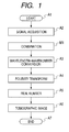
- FIG. 1 is an explanatory diagram illustrating signal processing steps according to a first embodiment of the present invention
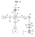
- FIG. 2 is an explanatory diagram illustrating a Michelson OCT apparatus according to the first embodiment of the present invention
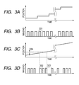
- FIGS. 3A, 3B, 3C, and 3D are explanatory charts illustrating a relation between a position of a scanner with respect to a lapse of time and measurement timing thereof according to the first embodiment of the present invention
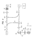
- FIG. 4 is an explanatory diagram illustrating a Mach-Zehnder OCT apparatus according to a second embodiment of the present invention
- FIGS. 5A and 5B are explanatory diagrams illustrating signal processing steps according to the second embodiment of the present invention.
- FIG. 6 is an explanatory diagram illustrating signal processing steps according to a third embodiment of the present invention.
- an optical tomographic image generation method of generating a tomographic image of an object including the steps of: acquiring a signal; performing Fourier transform; and obtaining the tomographic image, in which the optical tomographic image generation method further includes one of the steps of combining a plurality of the signals acquired within a predetermined time and combining a plurality of the signals acquired within a predetermined time after performing the Fourier transform thereon.
- FIG. 1 illustrates a case where the optical tomographic image generation method includes the step of combining a plurality of the signals acquired within a predetermined time.
- an imaging apparatus using a Michelson interferometer is employed for generating a tomographic image, but the imaging apparatus employable for the present invention is not limited thereto.
- signal processing of this embodiment is characterized in combining multiple signals after the signals are acquired.
- FIG. 2 is a schematic diagram illustrating the imaging apparatus using the Michelson optical system (Michelson interferometer) according to this embodiment.
- a light emitted from a light source 201 passes through a fiber 202 and a lens 203-1, and is split into a measurement light 214 and a reference light 213 by a beam splitter 204.
- the measurement light 214 passes through an XY scanner 208, an objective lens 205-1, and an objective lens 205-2, and enters an eye 217, which is an object. Then, the measurement light that has entered the eye passes through a cornea 216, and reaches a retina 218.
- a return light 215 reflected and scattered on the retina 218 of the eye 217 returns by passing through the objective lens 205-2, the objective lens 205-1, the XY scanner 208, and the beam splitter 204 in the stated order. Further, the return light 215 is guided to a spectrometer 211 through a lens 203-2.
- the spectrometer 211 includes a lens, a grating, and an image-pickup device. Used as the image-pickup device is a line sensor of a charge coupled device (CCD) type or a complementary metal oxide semiconductor (CMOS) type. Signals obtained by the line sensor of the spectrometer 211 are sent to a computer 212 and stored in a memory. The stored signals are then subjected to processing described later.
- CCD charge coupled device
- CMOS complementary metal oxide semiconductor
- the reference light 213 passes through a dispersion compensation glass 207, is reflected on a reference mirror 209, passes again through the dispersion compensation glass 207, and returns to the beam splitter 204.
- the dispersion compensation glass 207 is used for compensating for dispersion caused in the eye 217 and the objective lenses 205-1 and 205-2.
- the reference mirror 209 can adjust an optical path length of a reference light path by means of a mirror adjustment mechanism 210. Those reference light 213 and return light 215 are combined by the beam splitter 204. Then, the combined light is guided to the spectrometer 211. Note that, a portion on a measurement light path having an optical path length matching with that of the reference light path is referred to as a coherence gate. In a case where the retina 218 of the eye 217 is measured, the position of the reference mirror 209 is adjusted so that the coherence gate becomes close to the retina 218.
- the light source 201 a super luminescent diode (SLD), which is a typical low coherent light source, is used.
- the wavelength thereof for example, the center wavelength is 840 nm and the bandwidth is 50 nm.
- the bandwidth is an important parameter because of its influence on the resolution of a tomographic image to be obtained in an optical axis direction.
- the type of the selected light source 201 is the SLD herein, and alternatively, amplified spontaneous emission (ASE) may be used therefor as long as the light source 201 emits low coherent light.
- ASE amplified spontaneous emission
- another light source such as a halogen lamp may be used.
- the wavelength influences resolution of the tomographic image to be obtained in a lateral direction, and hence a short wavelength is desired when the resolution in the lateral direction is important.
- the computer 212 performs arithmetic processing and control that are described later, and also controls the spectrometer 211, the XY scanner 208, the mirror adjustment mechanism 210, and a focus adjustment mechanism 206. Obviously, the computer 212 is also capable of data input, image processing, image display, and data storage.
- Steps A1 to A7 a combination step M1 is provided between Steps A2 and A3.
- Step A1 measurement is started.
- the OCT apparatus is activated and an eye as an object is set for the measurement. Additionally, adjustment necessary for the measurement is performed by an operator so that the measurement is started.
- Step A2 signals are acquired.
- the XY scanner 208 is moved in an X direction of FIG. 2 , which is perpendicular to the optical axis of the eye 217.
- FIGS. 3A to 3D are charts illustrating a relation between a position of the XY scanner 208 with respect to a lapse of time and imaging timing thereof.
- FIG. 3A illustrates a case where the XY scanner 208 moves in the X direction stepwise.
- the number of steps is, for example, 512.
- the XY scanner 208 may be moved in the X direction successively as illustrated in FIG. 3C .
- the successive movement reduces loads on the scanner and leads to smooth movement as compared with the above-mentioned case.
- the measurement intervals may be equal, and alternatively, such different intervals as a measurement interval 302 and a measurement interval 303 as illustrated in FIG. 3D may be provided.
- regular intervals are provided among three successive imaging operations for obtaining signals to be combined, while a different measurement interval is provided between adjacent two sets of the imaging operations.
- the combination of the position control and the imaging timing is freely determined.
- the position control of the successive movement illustrated in FIG. 3C and the regular imaging timing illustrated in FIG. 3B may be employed in combination.
- a moving distance 304 be equal to or smaller than a several-fold length of the lateral resolution of the OCT apparatus (generally determined based on a beam diameter of the measurement light on the object). Specifically, the moving distance 304 ranges from several micrometers to several hundred micrometers.
- the predetermined distance may be converted into a time, and the time thus obtained may be set as a predetermined time. As long as the condition of the predetermined distance or the predetermined time is satisfied, the data may be acquired by rotating the XY scanner 208 like circle scanning instead of linear movement in the X or Y direction.
- Step M1 the signals are combined.
- one-dimensional arrays of adjacent three spectra are averaged and a new one-dimensional array is created.
- one-dimensional arrays of 3j-th, (3j+1)th, and (3j+2)th columns (j is an integer ranging from 0 to 511) are averaged.
- j is an integer ranging from 0 to 511) are averaged.
- a 1,024 ⁇ 512 two-dimensional array is obtained.
- noise components may be removed.
- calculation may be performed with a smaller number of data, which leads to an effect of shortening the calculation time.
- the averaging may be weighted averaging, but the noise removal effect may vary when the weights are different.
- the number of lines to be averaged is not necessarily three in the case of the combination of control illustrated in FIGS. 3C and 3B , and may be an arbitrary integer that satisfies the condition of the lateral resolution described above. Further, data that is considered to have a measurement error may be removed.
- wavelength-wavenumber conversion is performed.
- data from the spectrometer 211 includes a wavelength and the intensity at the wavelength. Further, sampling is performed at regular intervals with regard to the wavelength.
- a function of intensity data with regard to the wavelength is created.
- each wavelength is converted into a wavenumber, and a function of intensity data with regard to the wavenumber is created.
- the wavenumber is an inverse of the wavelength, and hence 1,024 wavenumbers are allocated at regular intervals.
- intensity data corresponding to the wavenumbers is calculated.
- the calculation method to be employed is, for example, interpolation, which may be general linear interpolation or spline interpolation. In this case, a linear arithmetic operation is desired. As a result, a two-dimensional array of 1,024 ⁇ 512 elements including intensities at regular intervals with regard to the wavenumber is obtained.
- this step may obviously be omitted as long as an error due to the wavelength-wavenumber conversion is negligible.
- Step A4 Fourier transform is performed.
- the intensity values arranged at regular intervals with regard to the wavenumber are subjected to discrete Fourier transform for each column.
- a 1,024 ⁇ 512 two-dimensional array of complex numbers is obtained.
- an m-th row and a (1,024-m)th row of each column have the same intensity value because of the characteristics of the Fourier transform. Therefore, 0th to 511th rows are extracted and a 512 ⁇ 512 two-dimensional array of complex numbers is obtained.
- Step A5 the complex number data is converted into real number data. It is not the linear arithmetic operation that is used for converting the complex number into a real number. Therefore, averaging before Step A5 is fundamentally different from averaging after Step A5. The difference is described in a second embodiment.
- Step A6 a tomographic image is obtained.
- a range is further adjusted in the 512 ⁇ 512 two-dimensional array.
- the range to be adjusted is, for example, the ratio of a longitudinal length to a lateral length.
- the number of pixels is increased and decreased through interpolation.
- contrast is adjusted.
- the adjustment of the contrast refers to general correction of the y value used for image processing. As a result, an image suitable for doctor's diagnosis is obtained. Then, the obtained tomographic image is displayed on a display screen of the computer 212.
- Step A7 the process ends.
- the process starting from the measurement using the OCT apparatus to the image display has been described above, and alternatively, for example, the above-mentioned process may be applied to data of multiple frames acquired via a network, to thereby obtain an image with reduced noise from a single tomographic image.
- a high-quality image can be obtained by combining signals acquired within a predetermined time.
- an imaging apparatus using a Mach-Zehnder interferometer is employed for generating a tomographic image, but the imaging apparatus employable for the present invention is not limited thereto.
- signal processing of this embodiment is characterized in signal combination performed after Fourier transform.
- FIG. 4 is a schematic diagram illustrating the imaging apparatus using the Mach-Zehnder optical system according to this embodiment. Differences from the first embodiment are described below.
- a light emitted from the light source 201 passes through a fiber coupler 401-1, and is split into a measurement light 214 and the reference light 213.
- the measurement light enters a port 1 of a circulator 402-2, exits from a port 2 thereof, and reaches a lens 403-2. Further, the measurement light passes through a XY scanner 208, an objective lens 205-1, an objective lens 205-2, and a cornea 216 of an eye 217, and reaches a retina 218.
- the return light 215 scattered and reflected on the retina returns by passing through the objective lens 205-2, the objective lens 205-1, the XY scanner 208, and the lens 403-2, enters the port 2 of the circulator 402-2, exits from a port 3 thereof, and reaches a fiber coupler 401-2.
- the reference light 213 enters a port 1 of a circulator 402-1, exits from a port 2 thereof, passes through a lens 403-1 and a dispersion compensation glass 207, and is reflected on a reference mirror 209.
- the reflected reference light 213 returns to the port 2 of the circulator 402-1 by passing through the dispersion compensation glass 207 and the lens 403-1, exits from a port 3 of the circulator 402-1, and reaches the fiber coupler 401-2.
- the reference mirror 209 can adjust the optical path length by means of the mirror adjustment mechanism 210.
- the reference light 213 and the return light 215 are combined by the fiber coupler 401-2, and the combined light is guided to the spectrometer.
- FIG. 5A illustrates a case where, among Steps A1 to A7, a combination step M2 is provided between Steps A4 and A5.
- FIG. 5B illustrates a case where a combination step M3 is provided between Steps A5 and A6.
- Step M2 complex number data obtained in Step A4 are combined, and the resultant complex number data is passed to Step A5.
- simple averaging or weighted averaging is performed on the complex number data.
- Step M3 real number data calculated in Step A5 are combined, and the resultant real number data is passed to Step A6.
- simple averaging or weighted averaging is performed on the real number data.
- the value of Expression 2 is equal to or smaller than the value of Expression 3. This fact is important in the noise removal method. Specifically, in a case of random noise, a plus component and a minus component exist. When the two components are added together in the state of the complex number, those components are canceled. Therefore, in theory, when the steps of FIGS. 5A and 5B are compared with each other, noise is further reduced through the steps of FIG. 5A . In contrast, when real numbers are obtained and then added together, the cancellation effect is limited. Note that, in the first embodiment, the linear arithmetic operation is performed until the Fourier transform, and hence the same effect may be obtained as in the case of adding the components together in the state of the complex number. Note that, the simple averaging is rather desired than the weighted averaging because the noise is equivalent.
- Table 1 shows comparison in signal-to-noise ratio (SNR) between the processing involving the steps of FIG. 1 and the processing involving the steps of FIG. 5B .
- the unit is decibel.
- As the position control for the scanner the case of FIG. 3C where the position of the scanner is shifted successively is applied.
- As the imaging timing the case of FIG. 3B where sampling is performed at regular intervals is applied.
- the imaging object is centered on a macula of a normal eye, and a retina is measured in the range of approximately 6 mm.
- the number of lines is 2,048.
- the SNR used in this comparison refers to a ratio of a maximum value of each pixel to a minimum value of root mean squares (RMSs) of noise of the rows thereof.
- a high-quality image can be obtained by combining signals acquired within a predetermined time.
- phase adjustment is performed after the Fourier transform, and then signals are combined.
- Step P1 complex number data are subjected to phase adjustment.
- phases of arrays of three adjacent lines are adjusted.
- the data are converted into sets of polar coordinates.
- An amplitude component and a phase component can be obtained from the polar coordinates.
- the phase of the one-dimensional array of the (3j+1)th column is adjusted with reference to the phase of the 3j-th column (or the phase of the (3j+2)th column is adjusted with reference to a result of combination of the 3j-th column and the (3j+1)th column).
- new arrays are created by changing a phase component of the array of the (3j+1)th column. When the phase component is changed by, for example, 10 degrees from 0 degrees to 350 degrees, 36 different one-dimensional arrays may be obtained.
- Step M3 combination is performed.
- the one-dimensional array of the 3j-th column is combined with the 36 different one-dimensional arrays, respectively.
- simple averaging is performed, to thereby newly obtain 36 different arrays.
- Step A5 real number data are obtained. There are obtained 36 different arrays of real numbers from the 36 different arrays obtained through the combination.
- Step P2 selection is performed. From among the 36 different arrays obtained through the combination, an array in which the signal is maximum is selected. While the noise removal effect is mainly obtained in the first and second embodiments, the signal can be maximized in this embodiment. Further, in the case of random noise, the noise is random even with the phase adjustment, and hence the noise removal effect is still obtained.
- Step P3 it is determined whether or not the combination is finished. Specifically, the three lines in the 3j-th column to the (3j+2)th column are combined, to thereby create a new 3j-th column. It is determined whether or not such combination is finished for all j's. When the combination is finished, the processing proceeds to Step A6. When the combination is not finished, the processing returns to Step P1.
- a high-quality image can be obtained by using data of adjacent lines.
- optical tomographic image generation methods may be executed by using a computer with the procedure for performing the respective steps implemented by a computer program.
- aspects of the present invention can also be realized by a computer of a system or apparatus (or devices such as a CPU or MPU) that reads out and executes a program recorded on a memory device to perform the functions of the above-described embodiment(s), and by a method, the steps of which are performed by a computer of a system or apparatus by, for example, reading out and executing a program recorded on a memory device to perform the functions of the above-described embodiment(s).
- the program is provided to the computer for example via a network or from a recording medium of various types serving as the memory device (e.g., computer-readable medium).
- the system or apparatus, the program, and the recording medium where the program is stored are included as being within the scope of the present invention.
Landscapes
- Health & Medical Sciences (AREA)
- Life Sciences & Earth Sciences (AREA)
- Physics & Mathematics (AREA)
- Engineering & Computer Science (AREA)
- General Health & Medical Sciences (AREA)
- Nuclear Medicine, Radiotherapy & Molecular Imaging (AREA)
- Veterinary Medicine (AREA)
- Public Health (AREA)
- Surgery (AREA)
- Animal Behavior & Ethology (AREA)
- General Physics & Mathematics (AREA)
- Biophysics (AREA)
- Radiology & Medical Imaging (AREA)
- Biomedical Technology (AREA)
- Heart & Thoracic Surgery (AREA)
- Medical Informatics (AREA)
- Molecular Biology (AREA)
- Pathology (AREA)
- Signal Processing (AREA)
- Psychiatry (AREA)
- Physiology (AREA)
- Computer Vision & Pattern Recognition (AREA)
- Artificial Intelligence (AREA)
- Mathematical Physics (AREA)
- Ophthalmology & Optometry (AREA)
- Investigating Or Analysing Materials By Optical Means (AREA)
- Eye Examination Apparatus (AREA)
Applications Claiming Priority (1)
| Application Number | Priority Date | Filing Date | Title |
|---|---|---|---|
| JP2009244696A JP5036785B2 (ja) | 2009-10-23 | 2009-10-23 | 光断層画像生成方法及び光断層画像生成装置 |
Publications (1)
| Publication Number | Publication Date |
|---|---|
| EP2314986A1 true EP2314986A1 (fr) | 2011-04-27 |
Family
ID=43530922
Family Applications (1)
| Application Number | Title | Priority Date | Filing Date |
|---|---|---|---|
| EP20100188408 Withdrawn EP2314986A1 (fr) | 2009-10-23 | 2010-10-21 | Appareil de génération d'images tomographiques optiques et procédé de génération d'images tomographiques optiques |
Country Status (4)
| Country | Link |
|---|---|
| US (1) | US9103650B2 (fr) |
| EP (1) | EP2314986A1 (fr) |
| JP (1) | JP5036785B2 (fr) |
| CN (1) | CN102038485B (fr) |
Families Citing this family (13)
| Publication number | Priority date | Publication date | Assignee | Title |
|---|---|---|---|---|
| JP5306075B2 (ja) * | 2008-07-07 | 2013-10-02 | キヤノン株式会社 | 光干渉断層法を用いる撮像装置及び撮像方法 |
| JP5627260B2 (ja) | 2009-05-22 | 2014-11-19 | キヤノン株式会社 | 撮像装置および撮像方法 |
| JP5808119B2 (ja) | 2010-04-13 | 2015-11-10 | キヤノン株式会社 | 模型眼、光断層画像撮像装置の調整方法、及び評価方法 |
| JP2011257160A (ja) | 2010-06-04 | 2011-12-22 | Canon Inc | 光干渉断層撮像装置、光干渉断層撮像方法、およびプログラム |
| JP2012042348A (ja) | 2010-08-19 | 2012-03-01 | Canon Inc | 断層画像表示装置およびその制御方法 |
| JP5733960B2 (ja) | 2010-11-26 | 2015-06-10 | キヤノン株式会社 | 撮像方法および撮像装置 |
| US8517537B2 (en) | 2011-01-20 | 2013-08-27 | Canon Kabushiki Kaisha | Optical coherence tomographic imaging method and optical coherence tomographic imaging apparatus |
| US9161690B2 (en) | 2011-03-10 | 2015-10-20 | Canon Kabushiki Kaisha | Ophthalmologic apparatus and control method of the same |
| JP5901124B2 (ja) | 2011-03-10 | 2016-04-06 | キヤノン株式会社 | 撮像装置およびその制御方法 |
| JP6113720B2 (ja) * | 2011-06-24 | 2017-04-12 | ノースイースタン・ユニバーシティ | 光スペクトルの反射歪みを補償する位相補正 |
| JP5955163B2 (ja) | 2011-09-06 | 2016-07-20 | キヤノン株式会社 | 画像処理装置および画像処理方法 |
| JP2013057549A (ja) * | 2011-09-07 | 2013-03-28 | Sumitomo Electric Ind Ltd | 光断層画像取得方法 |
| US8781190B2 (en) * | 2012-08-13 | 2014-07-15 | Crystalvue Medical Corporation | Image-recognition method for assisting ophthalmic examination instrument |
Citations (3)
| Publication number | Priority date | Publication date | Assignee | Title |
|---|---|---|---|---|
| US20070222946A1 (en) * | 2006-03-24 | 2007-09-27 | Yasufumi Fukuma | Fundus Observation Device |
| US20080175465A1 (en) * | 2007-01-19 | 2008-07-24 | Thorlabs, Inc. | Optical Coherence Tomography Imaging System and Method |
| US20080234972A1 (en) * | 2007-03-23 | 2008-09-25 | Kabushi Kaisha Topcon | Optical image measurement device and image processing device |
Family Cites Families (15)
| Publication number | Priority date | Publication date | Assignee | Title |
|---|---|---|---|---|
| DE69227902T3 (de) * | 1991-04-29 | 2010-04-22 | Massachusetts Institute Of Technology, Cambridge | Vorrichtung für optische abbildung und messung |
| DE60119930T2 (de) * | 2000-07-10 | 2007-01-18 | University Health Network, Toronto | Verfahren und vorrichtung zur hochauflösenden kohärenten optischen abbildung |
| JP4149126B2 (ja) * | 2000-12-05 | 2008-09-10 | ジーイー・メディカル・システムズ・グローバル・テクノロジー・カンパニー・エルエルシー | 画像処理方法、画像処理装置および画像撮影装置 |
| US20030103212A1 (en) * | 2001-08-03 | 2003-06-05 | Volker Westphal | Real-time imaging system and method |
| JP4461259B2 (ja) * | 2006-08-09 | 2010-05-12 | 国立大学法人 筑波大学 | 光断層画像の処理方法 |
| JP5340947B2 (ja) * | 2006-11-02 | 2013-11-13 | ハイデルベルク・エンジニアリング・ゲー・エム・ベー・ハー | 網膜画像を取得する方法およびその装置 |
| JP2008142443A (ja) * | 2006-12-13 | 2008-06-26 | Fujifilm Corp | 光断層画像化装置 |
| JP5448353B2 (ja) * | 2007-05-02 | 2014-03-19 | キヤノン株式会社 | 光干渉断層計を用いた画像形成方法、及び光干渉断層装置 |
| JP4940070B2 (ja) * | 2007-09-10 | 2012-05-30 | 国立大学法人 東京大学 | 眼底観察装置、眼科画像処理装置及びプログラム |
| JP5306075B2 (ja) * | 2008-07-07 | 2013-10-02 | キヤノン株式会社 | 光干渉断層法を用いる撮像装置及び撮像方法 |
| JP5199031B2 (ja) * | 2008-11-05 | 2013-05-15 | 株式会社ニデック | 眼科撮影装置 |
| JP5339934B2 (ja) * | 2009-01-22 | 2013-11-13 | キヤノン株式会社 | 光断層撮像装置および光断層撮像方法 |
| JP5605998B2 (ja) * | 2009-03-06 | 2014-10-15 | キヤノン株式会社 | 光干渉断層撮像方法および装置 |
| JP5605999B2 (ja) * | 2009-03-06 | 2014-10-15 | キヤノン株式会社 | 光干渉断層撮像方法および装置 |
| JP4902721B2 (ja) * | 2009-10-23 | 2012-03-21 | キヤノン株式会社 | 光断層画像生成装置及び光断層画像生成方法 |
-
2009
- 2009-10-23 JP JP2009244696A patent/JP5036785B2/ja not_active Expired - Fee Related
-
2010
- 2010-09-29 US US12/893,393 patent/US9103650B2/en not_active Expired - Fee Related
- 2010-10-21 EP EP20100188408 patent/EP2314986A1/fr not_active Withdrawn
- 2010-10-22 CN CN201010515596.0A patent/CN102038485B/zh not_active Expired - Fee Related
Patent Citations (4)
| Publication number | Priority date | Publication date | Assignee | Title |
|---|---|---|---|---|
| US20070222946A1 (en) * | 2006-03-24 | 2007-09-27 | Yasufumi Fukuma | Fundus Observation Device |
| US20080175465A1 (en) * | 2007-01-19 | 2008-07-24 | Thorlabs, Inc. | Optical Coherence Tomography Imaging System and Method |
| US20080234972A1 (en) * | 2007-03-23 | 2008-09-25 | Kabushi Kaisha Topcon | Optical image measurement device and image processing device |
| JP2008237238A (ja) | 2007-03-23 | 2008-10-09 | Topcon Corp | 光画像計測装置、画像処理装置及びプログラム |
Also Published As
| Publication number | Publication date |
|---|---|
| CN102038485A (zh) | 2011-05-04 |
| US9103650B2 (en) | 2015-08-11 |
| US20110096333A1 (en) | 2011-04-28 |
| JP5036785B2 (ja) | 2012-09-26 |
| JP2011087814A (ja) | 2011-05-06 |
| CN102038485B (zh) | 2014-03-12 |
Similar Documents
| Publication | Publication Date | Title |
|---|---|---|
| EP2314986A1 (fr) | Appareil de génération d'images tomographiques optiques et procédé de génération d'images tomographiques optiques | |
| US8504141B2 (en) | Optical tomographic image generating apparatus and optical tomographic image generating method | |
| US8970849B2 (en) | Tomography apparatus and tomogram correction processing method | |
| US20130003077A1 (en) | Tomographic imaging apparatus and control apparatus for tomographic imaging apparatus | |
| US8390819B2 (en) | Optical coherence tomography method and optical coherence tomography apparatus that removes a mirror image of an adjacent region to the measurement region | |
| US8634081B2 (en) | Tomographic imaging method and tomographic imaging apparatus | |
| CN101822530B (zh) | 光学相干层析摄影方法和光学相干层析摄影装置 | |
| US9058652B2 (en) | Method for reducing noise in tomographic image and recording medium having noise reducing program stored therein | |
| US10420462B2 (en) | Image processing apparatus that generates a tomographic image of a subject based on phase-adjusted measurement signals from which a background signal is subtracted, and related imaging apparatus, image processing method, and computer readable storage medium | |
| JP2010246654A (ja) | 光断層画像撮像装置及びその制御方法 | |
| JP5948757B2 (ja) | 眼底撮影装置 | |
| JP2011212206A (ja) | 撮像装置及び撮像方法 | |
| US10653310B2 (en) | Imaging apparatus, control method for an imaging apparatus, and program | |
| US10188286B2 (en) | Tomographic image capturing device | |
| WO2011121999A1 (fr) | Appareil et procédé d'imagerie | |
| JP6042573B2 (ja) | 画像処理装置、画像処理方法及び画像処理プログラム | |
| JP2012021794A (ja) | 光干渉計測データ読出方法、光干渉断層診断装置および光干渉断層診断システム | |
| JP5451822B2 (ja) | 光断層画像生成方法及び光断層画像生成装置 | |
| JP6047202B2 (ja) | 光干渉断層撮像装置、光干渉断層撮像方法、およびプログラム | |
| EP3375349B1 (fr) | Appareil de traitement d'informations, procédé de génération d'image et support lisible sur ordinateur | |
| JP5746741B2 (ja) | 画像生成装置、画像生成システム及び画像生成方法 | |
| JP5395888B2 (ja) | 画像生成装置、画像生成システム及び画像生成方法 |
Legal Events
| Date | Code | Title | Description |
|---|---|---|---|
| PUAI | Public reference made under article 153(3) epc to a published international application that has entered the european phase |
Free format text: ORIGINAL CODE: 0009012 |
|
| AK | Designated contracting states |
Kind code of ref document: A1 Designated state(s): AL AT BE BG CH CY CZ DE DK EE ES FI FR GB GR HR HU IE IS IT LI LT LU LV MC MK MT NL NO PL PT RO RS SE SI SK SM TR |
|
| AX | Request for extension of the european patent |
Extension state: BA ME |
|
| 17P | Request for examination filed |
Effective date: 20111027 |
|
| STAA | Information on the status of an ep patent application or granted ep patent |
Free format text: STATUS: THE APPLICATION HAS BEEN WITHDRAWN |
|
| 18W | Application withdrawn |
Effective date: 20150723 |