EP2314968A2 - Wärmeaufnahme- oder -ableitvorrichtung mit nach dem Temperaturunterschied versetztem und gleichförmig verteiltem Leitungswerk - Google Patents
Wärmeaufnahme- oder -ableitvorrichtung mit nach dem Temperaturunterschied versetztem und gleichförmig verteiltem Leitungswerk Download PDFInfo
- Publication number
- EP2314968A2 EP2314968A2 EP10187801A EP10187801A EP2314968A2 EP 2314968 A2 EP2314968 A2 EP 2314968A2 EP 10187801 A EP10187801 A EP 10187801A EP 10187801 A EP10187801 A EP 10187801A EP 2314968 A2 EP2314968 A2 EP 2314968A2
- Authority
- EP
- European Patent Office
- Prior art keywords
- fluid
- piping
- heat absorbing
- dissipating
- heat
- Prior art date
- Legal status (The legal status is an assumption and is not a legal conclusion. Google has not performed a legal analysis and makes no representation as to the accuracy of the status listed.)
- Withdrawn
Links
- 239000012530 fluid Substances 0.000 claims abstract description 360
- 238000010521 absorption reaction Methods 0.000 claims abstract description 50
- 230000017525 heat dissipation Effects 0.000 claims abstract description 42
- 230000005540 biological transmission Effects 0.000 claims description 62
- 239000007788 liquid Substances 0.000 claims description 53
- 238000001816 cooling Methods 0.000 claims description 28
- 238000010792 warming Methods 0.000 claims description 22
- 239000000084 colloidal system Substances 0.000 claims description 21
- 239000007787 solid Substances 0.000 claims description 21
- 238000005086 pumping Methods 0.000 claims description 13
- 230000000694 effects Effects 0.000 claims description 9
- 238000010438 heat treatment Methods 0.000 claims description 9
- 239000004020 conductor Substances 0.000 claims description 6
- 230000002457 bidirectional effect Effects 0.000 claims description 5
- 238000004378 air conditioning Methods 0.000 claims description 4
- 238000010411 cooking Methods 0.000 claims description 4
- 239000000498 cooling water Substances 0.000 claims description 4
- 230000000737 periodic effect Effects 0.000 claims description 4
- XLYOFNOQVPJJNP-UHFFFAOYSA-N water Substances O XLYOFNOQVPJJNP-UHFFFAOYSA-N 0.000 claims description 4
- 239000004566 building material Substances 0.000 claims description 2
- 238000005485 electric heating Methods 0.000 claims description 2
- 239000000446 fuel Substances 0.000 claims description 2
- 238000009434 installation Methods 0.000 claims description 2
- 238000004519 manufacturing process Methods 0.000 claims description 2
- 238000010248 power generation Methods 0.000 claims description 2
- 230000005855 radiation Effects 0.000 claims description 2
- 239000004065 semiconductor Substances 0.000 claims description 2
- 238000009423 ventilation Methods 0.000 claims description 2
- 238000010586 diagram Methods 0.000 description 12
- 230000007547 defect Effects 0.000 description 1
- 238000001704 evaporation Methods 0.000 description 1
- 230000008020 evaporation Effects 0.000 description 1
- 238000000034 method Methods 0.000 description 1
Images




Classifications
-
- F—MECHANICAL ENGINEERING; LIGHTING; HEATING; WEAPONS; BLASTING
- F28—HEAT EXCHANGE IN GENERAL
- F28D—HEAT-EXCHANGE APPARATUS, NOT PROVIDED FOR IN ANOTHER SUBCLASS, IN WHICH THE HEAT-EXCHANGE MEDIA DO NOT COME INTO DIRECT CONTACT
- F28D1/00—Heat-exchange apparatus having stationary conduit assemblies for one heat-exchange medium only, the media being in contact with different sides of the conduit wall, in which the other heat-exchange medium is a large body of fluid, e.g. domestic or motor car radiators
- F28D1/02—Heat-exchange apparatus having stationary conduit assemblies for one heat-exchange medium only, the media being in contact with different sides of the conduit wall, in which the other heat-exchange medium is a large body of fluid, e.g. domestic or motor car radiators with heat-exchange conduits immersed in the body of fluid
- F28D1/04—Heat-exchange apparatus having stationary conduit assemblies for one heat-exchange medium only, the media being in contact with different sides of the conduit wall, in which the other heat-exchange medium is a large body of fluid, e.g. domestic or motor car radiators with heat-exchange conduits immersed in the body of fluid with tubular conduits
- F28D1/047—Heat-exchange apparatus having stationary conduit assemblies for one heat-exchange medium only, the media being in contact with different sides of the conduit wall, in which the other heat-exchange medium is a large body of fluid, e.g. domestic or motor car radiators with heat-exchange conduits immersed in the body of fluid with tubular conduits the conduits being bent, e.g. in a serpentine or zig-zag
- F28D1/0477—Heat-exchange apparatus having stationary conduit assemblies for one heat-exchange medium only, the media being in contact with different sides of the conduit wall, in which the other heat-exchange medium is a large body of fluid, e.g. domestic or motor car radiators with heat-exchange conduits immersed in the body of fluid with tubular conduits the conduits being bent, e.g. in a serpentine or zig-zag the conduits being bent in a serpentine or zig-zag
-
- F—MECHANICAL ENGINEERING; LIGHTING; HEATING; WEAPONS; BLASTING
- F28—HEAT EXCHANGE IN GENERAL
- F28D—HEAT-EXCHANGE APPARATUS, NOT PROVIDED FOR IN ANOTHER SUBCLASS, IN WHICH THE HEAT-EXCHANGE MEDIA DO NOT COME INTO DIRECT CONTACT
- F28D7/00—Heat-exchange apparatus having stationary tubular conduit assemblies for both heat-exchange media, the media being in contact with different sides of a conduit wall
- F28D7/0066—Multi-circuit heat-exchangers, e.g. integrating different heat exchange sections in the same unit or heat-exchangers for more than two fluids
-
- F—MECHANICAL ENGINEERING; LIGHTING; HEATING; WEAPONS; BLASTING
- F28—HEAT EXCHANGE IN GENERAL
- F28D—HEAT-EXCHANGE APPARATUS, NOT PROVIDED FOR IN ANOTHER SUBCLASS, IN WHICH THE HEAT-EXCHANGE MEDIA DO NOT COME INTO DIRECT CONTACT
- F28D7/00—Heat-exchange apparatus having stationary tubular conduit assemblies for both heat-exchange media, the media being in contact with different sides of a conduit wall
- F28D7/08—Heat-exchange apparatus having stationary tubular conduit assemblies for both heat-exchange media, the media being in contact with different sides of a conduit wall the conduits being otherwise bent, e.g. in a serpentine or zig-zag
-
- F—MECHANICAL ENGINEERING; LIGHTING; HEATING; WEAPONS; BLASTING
- F28—HEAT EXCHANGE IN GENERAL
- F28F—DETAILS OF HEAT-EXCHANGE AND HEAT-TRANSFER APPARATUS, OF GENERAL APPLICATION
- F28F13/00—Arrangements for modifying heat-transfer, e.g. increasing, decreasing
- F28F13/06—Arrangements for modifying heat-transfer, e.g. increasing, decreasing by affecting the pattern of flow of the heat-exchange media
- F28F13/10—Arrangements for modifying heat-transfer, e.g. increasing, decreasing by affecting the pattern of flow of the heat-exchange media by imparting a pulsating motion to the flow, e.g. by sonic vibration
-
- F—MECHANICAL ENGINEERING; LIGHTING; HEATING; WEAPONS; BLASTING
- F28—HEAT EXCHANGE IN GENERAL
- F28F—DETAILS OF HEAT-EXCHANGE AND HEAT-TRANSFER APPARATUS, OF GENERAL APPLICATION
- F28F2210/00—Heat exchange conduits
- F28F2210/02—Heat exchange conduits with particular branching, e.g. fractal conduit arrangements
-
- F—MECHANICAL ENGINEERING; LIGHTING; HEATING; WEAPONS; BLASTING
- F28—HEAT EXCHANGE IN GENERAL
- F28F—DETAILS OF HEAT-EXCHANGE AND HEAT-TRANSFER APPARATUS, OF GENERAL APPLICATION
- F28F2210/00—Heat exchange conduits
- F28F2210/10—Particular layout, e.g. for uniform temperature distribution
-
- F—MECHANICAL ENGINEERING; LIGHTING; HEATING; WEAPONS; BLASTING
- F28—HEAT EXCHANGE IN GENERAL
- F28F—DETAILS OF HEAT-EXCHANGE AND HEAT-TRANSFER APPARATUS, OF GENERAL APPLICATION
- F28F2250/00—Arrangements for modifying the flow of the heat exchange media, e.g. flow guiding means; Particular flow patterns
- F28F2250/08—Fluid driving means, e.g. pumps, fans
-
- F—MECHANICAL ENGINEERING; LIGHTING; HEATING; WEAPONS; BLASTING
- F28—HEAT EXCHANGE IN GENERAL
- F28F—DETAILS OF HEAT-EXCHANGE AND HEAT-TRANSFER APPARATUS, OF GENERAL APPLICATION
- F28F2250/00—Arrangements for modifying the flow of the heat exchange media, e.g. flow guiding means; Particular flow patterns
- F28F2250/10—Particular pattern of flow of the heat exchange media
- F28F2250/102—Particular pattern of flow of the heat exchange media with change of flow direction
Definitions
- the present invention relates to the heat absorbing or dissipating device with piping staggered and uniformly distributed from both sides toward the middle by temperature difference of passed fluid, wherein the temperature difference fluid passes through the neighboring piping of the heat absorbing or dissipating device, and the synthetic temperature in the device is more uniform, so as to produce heat absorbing or dissipating function onto the passively heat dissipation or absorption receiving article or space thereby forming a more uniform temperature distribution status on the passively heat dissipation or absorption receiving article or space.
- thermal conductive fluid as the heat absorbing or dissipating body constituted by gaseous or liquid state fluid, gaseous to liquid state fluid, or liquid to gaseous state fluid such as engine cooling water radiators, heat absorbing cooling energy discharge devices utilizing thermal conductive fluid, or heat dissipating warming energy discharge devices utilizing thermal conductive fluid such as warming devices, heaters, or the warming energy transfer device, as the flow direction of the thermal conductive fluid is fixed, larger temperature difference is formed at each position on the heat absorbing or dissipating body of the thermal conductive fluid.
- the present invention discloses that the conventional application device transmitting thermal conductive fluid to pass through the heat absorbing or dissipating body for heat absorption or dissipation is improved to be a heat absorbing or dissipating device with piping staggered and uniformly distributed from both sides toward the middle according to the temperature difference of passed fluid, causing the synthetic temperature of the fluid heat absorbing or dissipating device with temperature differene fluid for the neighboring piping passing through to become more uniform, so as to produce heat absorbing or dissipating function onto the passively heat dissipation or absorption receiving article or space thereby forming a more uniform temperature distribution status on the passively heat dissipation or absorption receiving article or space.
- FIG. 1 is a main structural schematic view of a conventional heat absorbing or dissipating device for being passed through by thermal conductive fluid at fixed flow direction being constituted by heat absorbing or dissipating gaseous or liquid state fluid or gaseous to liquid state fluid, or liquid to gaseous state fluid. As shown in FIG.
- the heat absorbing or dissipating device assembly is conventionally composed by the thermal conductive fluid 110, which is constituted by gaseous or liquid state fluid, or gaseous to liquid state fluid, or liquid to gaseous state fluid, passing through the first fluid piping 101 to combine with the heat absorbing or dissipating thermal energy transmission body 100 for 1) passing through the thermal conductive fluid 110 in the fluid piping 101 to perform cooling or heating functions through the heat absorbing or dissipating thermal energy transmission body 100 onto passively heat dissipation or absorption receiving article in solid, or colloid, or liquid, or gaseous state or space 200; or 2) passing through the thermal conductive fluid 110 in the fluid piping 101 to reversely receive the surrounding cooling or heating energy of the heat absorbing or dissipating thermal energy transmission body 100 to perform cooling or heating functions; wherein the item 1) is often applied in engine cooling water radiators, heat absorbing cooling energy discharge devices utilizing the thermal conductive fluid 110, or heat dissipating warming energy discharge devices utilizing the thermal conductive fluid 110 such
- FIG. 2 is a temperature difference distribution diagram of FIG. 1 being operated for the heat absorbing cooling energy discharge device function.
- Fig 2 shows that the thermal conductive fluid 110 in unidiretional flow direction as shown in FIG. 1 being operated in the conventional heat dissipating warming energy discharge functions appears in unidirectional flow path distribution, wherein when the thermal conductive fluid 110 passes through the fluid piping 101, a larger temperature difference distribution status forms between the inlet and outlet of the thermal conductive fluid 110 of the heat absorbing or dissipating thermal energy transmission body 100.
- FIG. 3 is a temperature difference distribution diagram of FIG. 1 being operated for the heat dissipating warming energy discharge device function.
- FIG. 3 shows that the thermal conductive fluid 110 in unidirectional flow direction as shown in FIG. 1 being operated in the conventional heat absorbing cooling energy discharge function appears in unidirectional flow path distribution, wherein when the thermal conductive fluid 110 passes through the fluid piping 101, a larger temperature difference distribution status forms between the inlet and outlet of the thermal conductive fluid 110 of the heat absorbing or dissipating thermal energy transmission body 100.
- the present invention innovatively discloses a device with fluid piping staggered and uniformly distributed from both sides toward the middle by temperature difference of passed fluid, wherein the temperature difference fluid passes through the neighboring piping of the heat absorbing or dissipating device, and the synthetic temperature in the device is more uniform, so as to produce heat absorbing or dissipating function onto the passively heat dissipation or absorption receiving article or space thereby forming a more uniform temperature distribution status on the passively heat dissipation or absorption receiving article or space.
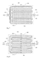
- FIG. 4 is a main structural schematic view of an embodiment, according to the present invention.
- the assembly structure of the heat absorbing or dissipating device with piping staggered and uniformly distributed by temperature difference mainly comprises the following:
- the structural relationships between the heat absorbing or dissipating thermal energy transmission body 100 and the fluid piping 101 as shown in Fig. 4 can be constituted by one or more relationships as following, including:
- FIG. 5 is a temperature difference distribution diagram formed on the structure shown in FIG. 4 being operated for heat absorbing cooling energy discharge device function.
- the fluid piping 101 is used for transmitting the thermal conductive fluids 110, wherien the inputting thermal conductive fluid 110 and the outputting thermal conductive fluid 110 has temperature difference between them, and the heat absorbing or dissipating thermal energy transmission body 100 demonstrates the middle temperature, which is more uniformly distributed, between the temperatures of the inputting thermal conductive fluid 110 and the outputting thermal conductive fluid 110, for performing the heat absorpting or dissipating function onto the passively heat dissipation or absorption receiving article in solid, or colloid, or liquid, or gaseous state or space 200 to prevent the local low temperature from being too low.
- FIG. 6 is a temperature difference distribution diagram formed on the structure shown in FIG. 4 being operated for heat dissipating warming energy discharge device function.
- the fluid piping 101 is used for transmitting the thermal conductive fluids 110, wherein the inputting thermal conductive fluid 110 and the outputting thermal conductive fluid 110 has temperature difference between them, and the heat absorbing or dissipating thermal energy transmission body 100 demonstrates the middle temperature, which is more uniformly distributed, between the temperatures of the inputting thermal conductive fluid 110 and the outputting thermal conductive fluid 110, for performing the heat absorpting or dissipating function onto the passively heat dissipation or absorption receiving article in solid, or colloid, or liquid, or gaseous state or space 200 to prevent the local high temperature from being too high.
- FIG. 7 shows another embodiment of the heat absorbing or dissipating device with piping staggered and uniformly distributed by temperature difference according to the present invention, wherein the fluid piping 101 is composed of two or more branching fluid piping, which are sequentially arranged from both sides toward the middle and gather together in the fluid piping 101.
- two branching fluid piping are exemplified in FIG.7 , wherein the two branching fluid piping arranged from both sides toward the middle for transmitting the thermal conductive fluid 110 with temperature difference include first branching fluid piping 1011 and second branching fluid piping 1012, which are sequentially arranged from both sides toward the middle and gather together in the fluid piping 101, so as to directly or through the heat absorbing or dissipating thermal energy transmission body 100 transmit thermal energy to the passively heat dissipation or absorption receiving article in solid, or colloid, or liquid, or gaseous state or space 200, the further structure including:
- the structural relationships between the heat absorbing or dissipating thermal energy transmission body 100 and the first branching fluid piping 1011 and/or the second branching fluid piping 1012 as shown in Fig. 7 can be constituted by one or more relationships as following, including:
- FIG. 8 is a temperature difference distribution diagram formed on the structure shown in FIG. 7 being operated for heat absorbing cooling energy discharge device function.
- FIG. 9 is a temperature difference distribution diagram formed on the structure shown in FIG. 7 being operated for heat dissipating warming energy discharge device function.
- the heat absorbing or dissipating device with piping staggered and uniformly distributed by temperature difference can be a common structural body directly constituted by the fluid piping 101, and/or thr first branching fluid piping 1011, and the second branching fluid piping 1012, and the passively heat dissipation or absorption receiving article in solid, or colloid, or liquid, or gaseous state or space 200.
- the fluid piping also can be parallel or quasi-parallel distributed in a plane structure or three-dimensional structure to construct the piping structural body transmitting the passively receiving heat absorbing or dissipating thermal conductive fluid 100' in place of the passively heat dissipation or absorption receiving article in solid, or colloid, or liquid, or gaseous state or space 200, and by means of the fluid piping 101 transmitting the thermal conductive fluid 110 constituted by gaseous or liquid state fluid, gaseous to liquid state fluid, or liquid to gaseous state fluid, thereby through the heat absorbing or dissipating thermal energy transmission body 100 transmits thermal energy to the piping structural body transmitting the passively receiving heat absorbing or dissipating thermal conductive fluid 100'.
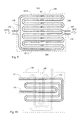
- FIG 10 shows an practical appliation that the fluid piping 101 showen in FIG. 4 is through the heat absorbing or dissipating thermal energy transmission body 100 combining with the piping structural body transmitting the passively receiving heat absorbing or dissipating thermal conductive fluid 100', according to the present invention.
- FIG. 11 shows another practical applicationthat the fluid piping 101, first branching fluid piping 1011, and second branching fluid piping 1012 showen in FIG.7 are through the heat absorbing or dissipating thermal energy transmission body 100 combining with the piping structural body transmitting the passively receiving heat absorbing or dissipating thermal conductive fluid 100', according to the present invention.
- FIG. 12 shows an practical application that the fluid piping 101 showen in FIG. 4 is through the heat absorbing or dissipating thermal energy transmission body 100 combining with multiple sets of the piping structural body transmitting the passively receiving heat absorbing or dissipating thermal conductive fluid 100', according to the present invention.
- FIG. 13 shows another practical application that the fluid piping 101, first branching fluid piping 1011, and second branching fluid piping 1012 showen in FIG.7 are through the heat absorbing or dissipating thermal energy transmission body 100 combining with multiple sets of the piping structural body transmitting the passively receiving heat absorbing or dissipating thermal conductive fluid 100', according to the present invention.
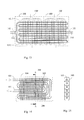
- the independent thermal conductive plate 300 is additionally installed at the fluid piping 101 and/or the piping structural body transmitting the passively receiving heat absorbing or dissipating thermal conductive fluid 100', so as to improve effects of heat absorption or dissipation.
- FIG. 14 is a structural schematic view of an embodiment, wherein the fluid piping 10 is additionally connected with independent thermal conductive plate 300, according to the present invention.
- FIG. 15 is a sectional drawing of line A-A in FIG. 14 .
- the common thermal conductive plate 400 is installed between the fluid piping 101 and/or the piping structural body transmitting the passively receiving heat absorbing or dissipating thermal conductive fluid 100', so as to improve effects of heat absorption or dissipation.
- FIG. 16 is a structural schematic view of an embodiment, wherein a common thermal conductive plate is installed between the fluid piping 101, according to the present invention.
- FIG 17 is a sectional drawing of line B-B in FIG. 16 .
- the thermal conductive plate 350 with temperature insulating slots is installed between the fluid piping 101 and/or the piping structural body transmitting the passively receiving heat absorbing or dissipating thermal conductive fluid 100', so as to improve effects of heat absorption or dissipation.
- FIG. 18 is a structural schematic view of an embodiment, wherein a thermal conductive plate with temperature insulating slots is installed between the fluid piping 101, according to the present invention.
- FIG. 19 is a sectional drawing of line C-C in FIG. 18 .
- the fluid passing through the fluid piping 101 and/or the piping structural body transmitting the passively receiving heat absorbing or dissipating thermal conductive fluid 100' can be controlled by the control device 500 to drive the bidirectional fluid pumping device 600 for periodic forward/reverse pumping operation, to periodically forward/reverse pump the thermal conductive fluid 110 bidirectionally, so as to improve effects of uniform temperature.
- the bidirectional fluid pumping device 600 is used for periodic forward/reverse pumping under the control of control device 500 constituted by the electromechanical device, electronic device, or microcomputer and related software.
- FIG. 20 is an operation system schematic view, wherein thermal conductive fluid 110 is periodically bi-directionally pumped by a bi-directional fluid pump, according to the present invention.
- the heat absorbing or dissipating device with piping staggered and uniformly distributed by temperature difference of the present invention can be applied for various heat absorbing, or heat dissipating, or cooling heat conducting application devices, such as the cooling water radiators of the engine, or cooling energy discharge device using thermal conductive fluid for heat absorbing, or warming energy discharge device using thermal conductive fluid for heat dissipating, such as thermal energy transfer for warming equipments, heater or thermal energy transfer devices, or heating or cooling for ceilings, walls or floors of the buildings, or cooling of photovoltaic panels, or heating or cooling for electrical machine or power machineries, or heat absorption and dissipation of various machine casings, heat pipe structures, structure casings, various chips or semiconductor components, ventilation devices, or the heat absorption, heat dissipation or thermal energy transfer for information, audio, image devices, various lamp or LED devices, or the heat absorption of the evaporator or heat dissipation or thermal energy transfer of condensers of air conditioning devices, or thermal energy transfer of mechanical devices,
Landscapes
- Engineering & Computer Science (AREA)
- Physics & Mathematics (AREA)
- Thermal Sciences (AREA)
- Mechanical Engineering (AREA)
- General Engineering & Computer Science (AREA)
- Filling Or Discharging Of Gas Storage Vessels (AREA)
- Thermotherapy And Cooling Therapy Devices (AREA)
- Cooling Or The Like Of Electrical Apparatus (AREA)
- Cooling Or The Like Of Semiconductors Or Solid State Devices (AREA)
Applications Claiming Priority (5)
| Application Number | Priority Date | Filing Date | Title |
|---|---|---|---|
| CN200920218696XU CN201715902U (zh) | 2009-10-16 | 2009-10-16 | 流路依温差交错均布的吸热或释热装置 |
| US12/588,468 US20110088881A1 (en) | 2009-10-16 | 2009-10-16 | Heat absorbing or dissipating device with piping staggered and uniformly distributed by temperature difference |
| TW098219191U TWM396600U (en) | 2009-10-16 | 2009-10-16 | Heat absorbing or disspating device with piping staggered and uniformly distributed by temperature difference |
| CN2009101799928A CN102042774A (zh) | 2009-10-16 | 2009-10-16 | 流路依温差交错均布的吸热或释热装置 |
| KR1020100110822A KR20120049525A (ko) | 2009-10-16 | 2010-11-09 | 배관이 온도차에 따라 교차된 상태로 균일하게 분포되는 흡열장치 또는 방열장치 |
Publications (2)
| Publication Number | Publication Date |
|---|---|
| EP2314968A2 true EP2314968A2 (de) | 2011-04-27 |
| EP2314968A3 EP2314968A3 (de) | 2011-07-06 |
Family
ID=51228829
Family Applications (1)
| Application Number | Title | Priority Date | Filing Date |
|---|---|---|---|
| EP10187801A Withdrawn EP2314968A3 (de) | 2009-10-16 | 2010-10-15 | Wärmeaufnahme- oder -ableitvorrichtung mit nach dem Temperaturunterschied versetztem und gleichförmig verteiltem Leitungswerk |
Country Status (11)
| Country | Link |
|---|---|
| US (1) | US20110088881A1 (de) |
| EP (1) | EP2314968A3 (de) |
| JP (1) | JP2011085384A (de) |
| KR (1) | KR20120049525A (de) |
| CN (2) | CN102042774A (de) |
| AU (1) | AU2010235861A1 (de) |
| BR (1) | BRPI1003952A2 (de) |
| CA (1) | CA2717562A1 (de) |
| RU (1) | RU2010142320A (de) |
| SG (1) | SG170688A1 (de) |
| TW (1) | TWM396600U (de) |
Families Citing this family (13)
| Publication number | Priority date | Publication date | Assignee | Title |
|---|---|---|---|---|
| US9322723B2 (en) | 2012-07-10 | 2016-04-26 | General Electric Company | Energy harvesting survey apparatus and method of detecting thermal energy |
| CN102818467B (zh) * | 2012-09-12 | 2014-06-18 | 锘威科技(深圳)有限公司 | 平板热管及其制作方法 |
| US20140083666A1 (en) * | 2012-09-27 | 2014-03-27 | Tai-Her Yang | Tri-Piece Thermal Energy Body Heat Exchanger Having Multi-Layer Pipeline and Transferring Heat to Exterior Through Outer Periphery of Pipeline |
| US9897400B2 (en) * | 2013-10-29 | 2018-02-20 | Tai-Her Yang | Temperature control system having adjacently-installed temperature equalizer and heat transfer fluid and application device thereof |
| US10415903B2 (en) * | 2014-10-15 | 2019-09-17 | Hamilton Sundstrand Corporation | Prevention of cooling flow blockage |
| ITUB20161177A1 (it) * | 2016-02-29 | 2017-08-29 | Torino Politecnico | Concio energetico modulare prefabbricato, rivestimento per gallerie realizzato con una pluralità di tali conci e metodo per scambiare calore in una galleria mediante la realizzazione di un rivestimento con una pluralità di tali conci |
| CN105744805A (zh) * | 2016-04-15 | 2016-07-06 | 周哲明 | 一种多通道组合水冷板 |
| CN108507184B (zh) * | 2018-03-21 | 2021-02-26 | 安徽省宁国市天成电气有限公司 | 一种电阻丝液体加热器 |
| DK3792576T3 (da) * | 2018-09-04 | 2023-01-09 | Ovh | Vandblok med en fluidledning |
| CN109404943A (zh) * | 2018-10-17 | 2019-03-01 | 上海康恒环境股份有限公司 | 低空气比高温燃烧水冷炉排 |
| CN111473546A (zh) * | 2020-04-23 | 2020-07-31 | 长虹美菱股份有限公司 | 一种制冷装置及其冰柜 |
| CN114325590B (zh) * | 2021-12-27 | 2023-05-30 | 北京微焓科技有限公司 | 一种相控阵雷达冷板及相控阵雷达 |
| US20230318079A1 (en) * | 2022-04-01 | 2023-10-05 | California Institute Of Technology | Multi-Functional Thermo-Mechanical Cellular Structure for the Containment and Thermal Control of Heat Generating and Heat Absorbing Components |
Family Cites Families (14)
| Publication number | Priority date | Publication date | Assignee | Title |
|---|---|---|---|---|
| DE2553967A1 (de) * | 1975-12-01 | 1977-06-02 | Gerhard Dipl Ing Pruefling | Fussbodenheizung |
| IL55047A0 (en) * | 1977-07-22 | 1978-08-31 | Carrier Corp | Heat exchange system |
| FR2549215B1 (fr) * | 1983-07-11 | 1988-06-24 | Produits Refractaires | Echangeurs de chaleur moules en matiere refractaire |
| JPS6113575A (ja) * | 1984-06-29 | 1986-01-21 | Fuji Electric Co Ltd | 燃料電池の冷却板構造 |
| JPH08247576A (ja) * | 1995-03-14 | 1996-09-27 | Toshiba Corp | 空気調和装置 |
| NL1001064C1 (nl) * | 1995-06-28 | 1995-11-15 | Fasting Corian Verwerking | Koelinrichting. |
| US6066408A (en) * | 1997-08-07 | 2000-05-23 | Plug Power Inc. | Fuel cell cooler-humidifier plate |
| US6581224B2 (en) * | 2001-03-06 | 2003-06-24 | Hyun Yoon | Bed heating systems |
| US6684941B1 (en) * | 2002-06-04 | 2004-02-03 | Yiding Cao | Reciprocating-mechanism driven heat loop |
| US7559356B2 (en) * | 2004-04-19 | 2009-07-14 | Eksident Technologies, Inc. | Electrokinetic pump driven heat transfer system |
| DE102007016106A1 (de) * | 2007-04-03 | 2008-10-09 | Lessing, Jürgen | Sicherheitswärmetauscher |
| DE102007034294A1 (de) * | 2007-07-24 | 2009-01-29 | BSH Bosch und Siemens Hausgeräte GmbH | Kältegerät und Verdampfer dafür |
| US8622116B2 (en) * | 2008-10-15 | 2014-01-07 | Tai-Her Yang | Heat absorbing or dissipating device with multi-pipe reversely transported temperature difference fluids |
| US8726979B2 (en) * | 2008-12-23 | 2014-05-20 | Tai-Her Yang | Heat exchange apparatus with automatic heat exchange fluid flow rate exchange modulation |
-
2009
- 2009-10-16 US US12/588,468 patent/US20110088881A1/en not_active Abandoned
- 2009-10-16 TW TW098219191U patent/TWM396600U/zh not_active IP Right Cessation
- 2009-10-16 CN CN2009101799928A patent/CN102042774A/zh active Pending
- 2009-10-16 CN CN200920218696XU patent/CN201715902U/zh not_active Expired - Fee Related
-
2010
- 2010-10-12 SG SG201007469-8A patent/SG170688A1/en unknown
- 2010-10-13 CA CA2717562A patent/CA2717562A1/en not_active Abandoned
- 2010-10-13 JP JP2010230370A patent/JP2011085384A/ja active Pending
- 2010-10-15 RU RU2010142320/06A patent/RU2010142320A/ru not_active Application Discontinuation
- 2010-10-15 EP EP10187801A patent/EP2314968A3/de not_active Withdrawn
- 2010-10-15 BR BRPI1003952-0A patent/BRPI1003952A2/pt not_active Application Discontinuation
- 2010-10-15 AU AU2010235861A patent/AU2010235861A1/en not_active Abandoned
- 2010-11-09 KR KR1020100110822A patent/KR20120049525A/ko not_active Withdrawn
Non-Patent Citations (1)
| Title |
|---|
| None |
Also Published As
| Publication number | Publication date |
|---|---|
| TWM396600U (en) | 2011-01-21 |
| BRPI1003952A2 (pt) | 2013-02-13 |
| RU2010142320A (ru) | 2012-04-20 |
| AU2010235861A1 (en) | 2011-05-12 |
| JP2011085384A (ja) | 2011-04-28 |
| SG170688A1 (en) | 2011-05-30 |
| EP2314968A3 (de) | 2011-07-06 |
| CA2717562A1 (en) | 2011-04-16 |
| CN201715902U (zh) | 2011-01-19 |
| KR20120049525A (ko) | 2012-05-17 |
| CN102042774A (zh) | 2011-05-04 |
| US20110088881A1 (en) | 2011-04-21 |
Similar Documents
| Publication | Publication Date | Title |
|---|---|---|
| EP2314969A2 (de) | Wärme absorbierende oder ableitende Vorrichtung mit Doppelrollleitung zur Übertragung einer Temperaturunterschiedflüssigkeit | |
| EP2314968A2 (de) | Wärmeaufnahme- oder -ableitvorrichtung mit nach dem Temperaturunterschied versetztem und gleichförmig verteiltem Leitungswerk | |
| EP2192369A2 (de) | Wärme absorbierende oder ableitende Vorrichtung mit durch mehrere Rohrleitungen in umgekehrter Richtung transportierten Temperaturdifferenzflüssigkeiten | |
| US20100089556A1 (en) | Heat absorbing or dissipating device with multi-pipe reversely transported temperature difference fluids | |
| US8607854B2 (en) | Fluid heat transfer device having plural counter flow circuits with periodic flow direction change therethrough | |
| US20160322932A1 (en) | Hybrid solar thermal system | |
| KR20110052818A (ko) | 다중 관로에 의하여 온도차를 가진 유체를 역전달하는 흡열장치 또는 방열장치 | |
| JP3165009U (ja) | 吸熱又は放熱装置 | |
| KR102284056B1 (ko) | 다중 배관에 의하여 온도차를 가진 유체를 역 전달하는 흡열 및 방열장치 | |
| CN204115291U (zh) | 液态半导体制冷换热模块和大功率液态半导体制冷换热器 | |
| CN105276854B (zh) | 液态半导体制冷换热模块和大功率液态半导体制冷换热器 | |
| WO2015173629A1 (en) | Radiant panel for space heating | |
| KR20190011295A (ko) | 다중 배관에 의하여 온도차를 가진 유체를 역전달하는 흡열 및 방열장치 | |
| KR20180003517A (ko) | 다중 배관에 의하여 온도차를 가진 유체를 역전달하는 흡열 및 방열장치 |
Legal Events
| Date | Code | Title | Description |
|---|---|---|---|
| PUAI | Public reference made under article 153(3) epc to a published international application that has entered the european phase |
Free format text: ORIGINAL CODE: 0009012 |
|
| AK | Designated contracting states |
Kind code of ref document: A2 Designated state(s): AL AT BE BG CH CY CZ DE DK EE ES FI FR GB GR HR HU IE IS IT LI LT LU LV MC MK MT NL NO PL PT RO RS SE SI SK SM TR |
|
| AX | Request for extension of the european patent |
Extension state: BA ME |
|
| PUAL | Search report despatched |
Free format text: ORIGINAL CODE: 0009013 |
|
| AK | Designated contracting states |
Kind code of ref document: A3 Designated state(s): AL AT BE BG CH CY CZ DE DK EE ES FI FR GB GR HR HU IE IS IT LI LT LU LV MC MK MT NL NO PL PT RO RS SE SI SK SM TR |
|
| AX | Request for extension of the european patent |
Extension state: BA ME |
|
| RIC1 | Information provided on ipc code assigned before grant |
Ipc: F28F 13/10 20060101ALI20110531BHEP Ipc: F28D 7/00 20060101ALI20110531BHEP Ipc: F28D 7/08 20060101ALI20110531BHEP Ipc: F28D 1/047 20060101AFI20110203BHEP |
|
| STAA | Information on the status of an ep patent application or granted ep patent |
Free format text: STATUS: THE APPLICATION IS DEEMED TO BE WITHDRAWN |
|
| 18D | Application deemed to be withdrawn |
Effective date: 20120110 |