EP2314969A2 - Wärme absorbierende oder ableitende Vorrichtung mit Doppelrollleitung zur Übertragung einer Temperaturunterschiedflüssigkeit - Google Patents
Wärme absorbierende oder ableitende Vorrichtung mit Doppelrollleitung zur Übertragung einer Temperaturunterschiedflüssigkeit Download PDFInfo
- Publication number
- EP2314969A2 EP2314969A2 EP10187809A EP10187809A EP2314969A2 EP 2314969 A2 EP2314969 A2 EP 2314969A2 EP 10187809 A EP10187809 A EP 10187809A EP 10187809 A EP10187809 A EP 10187809A EP 2314969 A2 EP2314969 A2 EP 2314969A2
- Authority
- EP
- European Patent Office
- Prior art keywords
- fluid
- piping
- heat absorbing
- dissipating
- heat
- Prior art date
- Legal status (The legal status is an assumption and is not a legal conclusion. Google has not performed a legal analysis and makes no representation as to the accuracy of the status listed.)
- Withdrawn
Links
Images






Classifications
-
- F—MECHANICAL ENGINEERING; LIGHTING; HEATING; WEAPONS; BLASTING
- F24—HEATING; RANGES; VENTILATING
- F24D—DOMESTIC- OR SPACE-HEATING SYSTEMS, e.g. CENTRAL HEATING SYSTEMS; DOMESTIC HOT-WATER SUPPLY SYSTEMS; ELEMENTS OR COMPONENTS THEREFOR
- F24D15/00—Other domestic- or space-heating systems
-
- F—MECHANICAL ENGINEERING; LIGHTING; HEATING; WEAPONS; BLASTING
- F28—HEAT EXCHANGE IN GENERAL
- F28D—HEAT-EXCHANGE APPARATUS, NOT PROVIDED FOR IN ANOTHER SUBCLASS, IN WHICH THE HEAT-EXCHANGE MEDIA DO NOT COME INTO DIRECT CONTACT
- F28D7/00—Heat-exchange apparatus having stationary tubular conduit assemblies for both heat-exchange media, the media being in contact with different sides of a conduit wall
- F28D7/0008—Heat-exchange apparatus having stationary tubular conduit assemblies for both heat-exchange media, the media being in contact with different sides of a conduit wall the conduits for one medium being in heat conductive contact with the conduits for the other medium
- F28D7/0016—Heat-exchange apparatus having stationary tubular conduit assemblies for both heat-exchange media, the media being in contact with different sides of a conduit wall the conduits for one medium being in heat conductive contact with the conduits for the other medium the conduits for one medium or the conduits for both media being bent
-
- F—MECHANICAL ENGINEERING; LIGHTING; HEATING; WEAPONS; BLASTING
- F24—HEATING; RANGES; VENTILATING
- F24D—DOMESTIC- OR SPACE-HEATING SYSTEMS, e.g. CENTRAL HEATING SYSTEMS; DOMESTIC HOT-WATER SUPPLY SYSTEMS; ELEMENTS OR COMPONENTS THEREFOR
- F24D3/00—Hot-water central heating systems
- F24D3/10—Feed-line arrangements, e.g. providing for heat-accumulator tanks, expansion tanks ; Hydraulic components of a central heating system
-
- F—MECHANICAL ENGINEERING; LIGHTING; HEATING; WEAPONS; BLASTING
- F24—HEATING; RANGES; VENTILATING
- F24H—FLUID HEATERS, e.g. WATER OR AIR HEATERS, HAVING HEAT-GENERATING MEANS, e.g. HEAT PUMPS, IN GENERAL
- F24H9/00—Details
-
- F—MECHANICAL ENGINEERING; LIGHTING; HEATING; WEAPONS; BLASTING
- F28—HEAT EXCHANGE IN GENERAL
- F28D—HEAT-EXCHANGE APPARATUS, NOT PROVIDED FOR IN ANOTHER SUBCLASS, IN WHICH THE HEAT-EXCHANGE MEDIA DO NOT COME INTO DIRECT CONTACT
- F28D1/00—Heat-exchange apparatus having stationary conduit assemblies for one heat-exchange medium only, the media being in contact with different sides of the conduit wall, in which the other heat-exchange medium is a large body of fluid, e.g. domestic or motor car radiators
- F28D1/02—Heat-exchange apparatus having stationary conduit assemblies for one heat-exchange medium only, the media being in contact with different sides of the conduit wall, in which the other heat-exchange medium is a large body of fluid, e.g. domestic or motor car radiators with heat-exchange conduits immersed in the body of fluid
- F28D1/04—Heat-exchange apparatus having stationary conduit assemblies for one heat-exchange medium only, the media being in contact with different sides of the conduit wall, in which the other heat-exchange medium is a large body of fluid, e.g. domestic or motor car radiators with heat-exchange conduits immersed in the body of fluid with tubular conduits
- F28D1/047—Heat-exchange apparatus having stationary conduit assemblies for one heat-exchange medium only, the media being in contact with different sides of the conduit wall, in which the other heat-exchange medium is a large body of fluid, e.g. domestic or motor car radiators with heat-exchange conduits immersed in the body of fluid with tubular conduits the conduits being bent, e.g. in a serpentine or zig-zag
- F28D1/0472—Heat-exchange apparatus having stationary conduit assemblies for one heat-exchange medium only, the media being in contact with different sides of the conduit wall, in which the other heat-exchange medium is a large body of fluid, e.g. domestic or motor car radiators with heat-exchange conduits immersed in the body of fluid with tubular conduits the conduits being bent, e.g. in a serpentine or zig-zag the conduits being helically or spirally coiled
-
- F—MECHANICAL ENGINEERING; LIGHTING; HEATING; WEAPONS; BLASTING
- F28—HEAT EXCHANGE IN GENERAL
- F28D—HEAT-EXCHANGE APPARATUS, NOT PROVIDED FOR IN ANOTHER SUBCLASS, IN WHICH THE HEAT-EXCHANGE MEDIA DO NOT COME INTO DIRECT CONTACT
- F28D7/00—Heat-exchange apparatus having stationary tubular conduit assemblies for both heat-exchange media, the media being in contact with different sides of a conduit wall
- F28D7/04—Heat-exchange apparatus having stationary tubular conduit assemblies for both heat-exchange media, the media being in contact with different sides of a conduit wall the conduits being spirally coiled
-
- F—MECHANICAL ENGINEERING; LIGHTING; HEATING; WEAPONS; BLASTING
- F28—HEAT EXCHANGE IN GENERAL
- F28F—DETAILS OF HEAT-EXCHANGE AND HEAT-TRANSFER APPARATUS, OF GENERAL APPLICATION
- F28F1/00—Tubular elements; Assemblies of tubular elements
- F28F1/10—Tubular elements and assemblies thereof with means for increasing heat-transfer area, e.g. with fins, with projections, with recesses
- F28F1/12—Tubular elements and assemblies thereof with means for increasing heat-transfer area, e.g. with fins, with projections, with recesses the means being only outside the tubular element
- F28F1/24—Tubular elements and assemblies thereof with means for increasing heat-transfer area, e.g. with fins, with projections, with recesses the means being only outside the tubular element and extending transversely
- F28F1/30—Tubular elements and assemblies thereof with means for increasing heat-transfer area, e.g. with fins, with projections, with recesses the means being only outside the tubular element and extending transversely the means being attachable to the element
-
- F—MECHANICAL ENGINEERING; LIGHTING; HEATING; WEAPONS; BLASTING
- F28—HEAT EXCHANGE IN GENERAL
- F28F—DETAILS OF HEAT-EXCHANGE AND HEAT-TRANSFER APPARATUS, OF GENERAL APPLICATION
- F28F1/00—Tubular elements; Assemblies of tubular elements
- F28F1/10—Tubular elements and assemblies thereof with means for increasing heat-transfer area, e.g. with fins, with projections, with recesses
- F28F1/12—Tubular elements and assemblies thereof with means for increasing heat-transfer area, e.g. with fins, with projections, with recesses the means being only outside the tubular element
- F28F1/24—Tubular elements and assemblies thereof with means for increasing heat-transfer area, e.g. with fins, with projections, with recesses the means being only outside the tubular element and extending transversely
- F28F1/32—Tubular elements and assemblies thereof with means for increasing heat-transfer area, e.g. with fins, with projections, with recesses the means being only outside the tubular element and extending transversely the means having portions engaging further tubular elements
-
- F—MECHANICAL ENGINEERING; LIGHTING; HEATING; WEAPONS; BLASTING
- F28—HEAT EXCHANGE IN GENERAL
- F28F—DETAILS OF HEAT-EXCHANGE AND HEAT-TRANSFER APPARATUS, OF GENERAL APPLICATION
- F28F1/00—Tubular elements; Assemblies of tubular elements
- F28F1/10—Tubular elements and assemblies thereof with means for increasing heat-transfer area, e.g. with fins, with projections, with recesses
- F28F1/12—Tubular elements and assemblies thereof with means for increasing heat-transfer area, e.g. with fins, with projections, with recesses the means being only outside the tubular element
- F28F1/24—Tubular elements and assemblies thereof with means for increasing heat-transfer area, e.g. with fins, with projections, with recesses the means being only outside the tubular element and extending transversely
- F28F1/32—Tubular elements and assemblies thereof with means for increasing heat-transfer area, e.g. with fins, with projections, with recesses the means being only outside the tubular element and extending transversely the means having portions engaging further tubular elements
- F28F1/325—Fins with openings
-
- F—MECHANICAL ENGINEERING; LIGHTING; HEATING; WEAPONS; BLASTING
- F28—HEAT EXCHANGE IN GENERAL
- F28F—DETAILS OF HEAT-EXCHANGE AND HEAT-TRANSFER APPARATUS, OF GENERAL APPLICATION
- F28F13/00—Arrangements for modifying heat-transfer, e.g. increasing, decreasing
- F28F13/06—Arrangements for modifying heat-transfer, e.g. increasing, decreasing by affecting the pattern of flow of the heat-exchange media
- F28F13/10—Arrangements for modifying heat-transfer, e.g. increasing, decreasing by affecting the pattern of flow of the heat-exchange media by imparting a pulsating motion to the flow, e.g. by sonic vibration
-
- F—MECHANICAL ENGINEERING; LIGHTING; HEATING; WEAPONS; BLASTING
- F28—HEAT EXCHANGE IN GENERAL
- F28F—DETAILS OF HEAT-EXCHANGE AND HEAT-TRANSFER APPARATUS, OF GENERAL APPLICATION
- F28F2210/00—Heat exchange conduits
- F28F2210/10—Particular layout, e.g. for uniform temperature distribution
-
- F—MECHANICAL ENGINEERING; LIGHTING; HEATING; WEAPONS; BLASTING
- F28—HEAT EXCHANGE IN GENERAL
- F28F—DETAILS OF HEAT-EXCHANGE AND HEAT-TRANSFER APPARATUS, OF GENERAL APPLICATION
- F28F2250/00—Arrangements for modifying the flow of the heat exchange media, e.g. flow guiding means; Particular flow patterns
- F28F2250/08—Fluid driving means, e.g. pumps, fans
Definitions
- the present invention relates to the heat absorbing or dissipating device with double-scroll piping transmitting temperature difference fluid, which is composed of one or more parallel or quasi-parallel installed fluid piping by series or parallel connection, and each piping is specifically distributed by one or more double-scroll arrangement for transmitting thermal conductive fluid with temperature difference constituted by gaseous or liquid state fluid, gaseous to liquid state fluid, or liquid to gaseous state fluid, and by means of the double-scroll fluid piping constituting the fluid flow uniformly distributed by temperature difference, thereby the fluids passing through neighboring piping flow in reverse direction, so as to produce heat absorbing or dissipating function onto the passively heat dissipation or absorption receiving article or space thereby forming a more uniform temperature distribution status on the passively heat dissipation or absorption receiving article or space.
- thermal conductive fluid as the heat absorbing or dissipating body constituted by gaseous or liquid state fluid, gaseous to liquid state fluid, or liquid to gaseous state fluid such as engine cooling water radiators, heat absorbing cooling energy discharge devices utilizing thermal conductive fluid, or heat dissipating warming energy discharge devices utilizing thermal conductive fluid such as warming devices, heaters, or the warming energy transfer device, as the flow direction of the thermal conductive fluid is fixed, larger temperature difference is formed between different positions on the heat absorbing or dissipating body of the thermal conductive fluid.
- the present invention relates to the heat absorbing or dissipating device with double-scroll piping transmitting temperature difference fluid, which is composed of one or more parallel or quasi-parallel installed fluid piping in series or parallel connection, and each piping is specifically distributed by one or more double-scroll arrangement for transmitting thermal conductive fluid with temperature difference constituted by gaseous or liquid state fluid, gaseous to liquid state fluid, or liquid to gaseous state fluid.
- FIG 1 is a main structural schematic view of a conventional heat absorbing or dissipating device for being passed through by thermal conductive fluid at fixed flow direction being constituted by heat absorbing or dissipating gaseous or liquid state fluid or gaseous to liquid state fluid, or liquid to gaseous state fluid. As shown in FIG.
- the heat absorbing or dissipating device assembly conventionally is composed by the thermal conductive fluid 110, which is constituted by gaseous or liquid state fluid, or gaseous to liquid state fluid, or liquid to gaseous state fluid, passing through the fluid piping 101 to combine with the heat absorbing or dissipating thermal energy transmission body 100 for 1) passing through the thermal conductive fluid 110 in the fluid piping 101 to perform cooling or heating functions through the heat absorbing or dissipating thermal energy transmission body 100 onto passively heat dissipation or absorption receiving article in solid, or colloid, or liquid, or gaseous state or space 200; or 2) passing through the thermal conductive fluid 110 in the fluid piping 101 to reversely receive the surrounding cooling or heating energy of the heat absorbing or dissipating thermal energy transmission body 100 to perform cooling or heating functions; wherein the item 1 ) is often applied in engine cooling water radiators, heat absorbing cooling energy discharge devices utilizing the thermal conductive fluid 110, or heat dissipating warming energy discharge devices utilizing the thermal conductive fluid 110
- FIG. 2 is a temperature difference distribution diagram of FIG. 1 being operated for the heat absorbing cooling energy discharge device function.
- Fig 2 shows that the thermal conductive fluid 110 in unidirectional flow direction as shown in FIG. 1 being operated in the conventional heat dissipating warming energy discharge functions appears in unidirectional flow path distribution, wherein when the thermal conductive fluid 110 passes through the fluid piping 101, a larger temperature difference distribution status forms between the inlet and outlet of the thermal conductive fluid 110 of the heat absorbing or dissipating thermal energy transmission body 100.
- FIG. 3 is a temperature difference distribution diagram of FIG. 1 being operated for the heat dissipating warming energy discharge device function.
- FIG. 3 shows that the thermal conductive fluid 110 in unidirectional flow direction as shown in FIG. 1 being operated in the conventional heat absorbing cooling energy discharge function appears in unidirectional flow path distribution, wherein when the thermal conductive fluid 110 passes through the fluid piping 101, a larger temperature difference distribution status forms between the inlet and outlet of the thermal conductive fluid 110 of the heat absorbing or dissipating thermal energy transmission body 100.
- the present invention innovatively discloses a heat absorbing or dissipating device by thermal conductive fluid passing through, wherein the piping with double-scroll arrangement transmits the temperature difference fluids in different flow directions according to the temperature difference, so as to produce heat absorbing or dissipating function onto the passively heat dissipation or absorption receiving article or space, thereby forming a more uniform temperature distribution status on the passively heat dissipation or absorption receiving article or space.
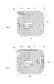
- FIG. 4 is a main structural schematic view of an embodiment, according to the present invention. As shown in FIG. 4 , the main structure comprises the following:
- the structural relationships between the heat absorbing or dissipating thermal energy transmission body 100 and the fluid piping 101 as shown in Fig. 4 can be constituted by one or more relationships as following, including:
- FIG. 5 is a temperature difference distribution diagram formed on the structure shown in FIG. 4 being operated for heat absorbing cooling energy discharge device function.
- the thermal conductive fluid 110 passing through inlet of the fluid piping 101 is at lower temperature
- the thermal conductive fluid 110 passing through outlet of the fluid piping 101 is at higher temperature
- the heat absorbing or dissipating thermal energy transmission body 100 demonstrates the middle temperature, which is more uniformly distributed, between the temperatures of the inputting thermal conductive fluid 110 and the outputting thermal conductive fluid 110, for performing the heat absorbing and cooling energy discharge function onto the passively heat dissipation or absorption receiving article in solid, or colloid, or liquid, or gaseous state or space 200 to prevent the local low temperature from being too low.
- FIG. 6 is a temperature difference distribution diagram formed on the structure shown in FIG. 4 being operated for heat dissipating warming energy discharge device function.
- the thermal conductive fluid 110 passing through inlet of the fluid piping 101 is at higher temperature
- the thermal conductive fluid 110 passing through outlet of the fluid piping 101 is at lower temperature
- the heat absorbing or dissipating thermal energy transmission body 100 demonstrates the middle temperature, which is more uniformly distributed, between the temperatures of the inputting thermal conductive fluid 110 and the outputting thermal conductive fluid 110, for performing the heat dissipating and warming energy discharge function onto the passively heat dissipation or absorption receiving article in solid, or colloid, or liquid, or gaseous state or space 200 to prevent the local high temperature from being too high.
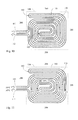
- FIG. 7 is a main structural schematic view of another embodiment, according to the present invention. As shown in FIG. 7 , the further structure including:
- the structural relationships between the heat absorbing or dissipating thermal energy transmission body 100 and the fluid piping 101 as shown in Fig. 7 can be constituted by one or more relationships as following, including:
- FIG. 8 is a temperature difference distribution diagram formed on the structure shown in FIG 7 being operated for heat absorbing cooling energy discharge device function.
- the thermal conductive fluid 110 passing through inlet of the fluid piping 101 is at lower temperature
- the thermal conductive fluid 110 passing through outlet of the fluid piping 101 is at higher temperature
- the heat absorbing or dissipating thermal energy transmission body 100 demonstrates the middle temperature, which is more uniformly distributed, between the temperatures of the inputting thermal conductive fluid 110 and the outputting thermal conductive fluid 110, for performing the heat absorbing and cooling energy discharge function onto the passively heat dissipation or absorption receiving article in solid, or colloid, or liquid, or gaseous state or space 200 to prevent the local low temperature from being too low.
- FIG. 9 is a temperature difference distribution diagram formed on the structure shown in FIG. 7 being operated for heat dissipating warming energy discharge device function.
- the thermal conductive fluid 110 passing through inlet of the fluid piping 101 is at higher temperature
- the thermal conductive fluid 110 passing through outlet of the fluid piping 101 is at lower temperature
- the heat absorbing or dissipating thermal energy transmission body 100 demonstrates the middle temperature, which is more uniformly distributed, between the temperatures of the inputting thermal conductive fluid 110 and the outputting thermal conductive fluid 110, for performing the heat dissipating and warming energy discharge function onto the passively heat dissipation or absorption receiving article in solid, or colloid, or liquid, or gaseous state or space 200 to prevent the local high temperature from being too high.
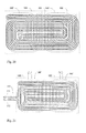
- FIG. 10 is a main structural schematic view of still another embodiment, according to the present invention. As shown in FIG. 10 , the further structure including:
- the structural relationships between the heat absorbing or dissipating thermal energy transmission body 100 and the fluid piping 101 as shown in Fig. 10 can be constituted by one or more relationships as following, including:
- FIG. 11 is a temperature difference distribution diagram formed on the structure shown in FIG. 10 being operated for heat absorbing cooling energy discharge device function.
- the thermal conductive fluid 110 passing through inlet of the fluid piping 101 is at lower temperature
- the thermal conductive fluid 110 passing through outlet of the fluid piping 101 1 is at higher temperature
- the heat absorbing or dissipating thermal energy transmission body 100 demonstrates the middle temperature, which is more uniformly distributed, between the temperatures of the inputting thermal conductive fluid 110 and the outputting thermal conductive fluid 110, for performing the heat absorbing and cooling energy discharge function onto the passively heat dissipation or absorption receiving article in solid, or colloid, or liquid, or gaseous state or space 200 to prevent the local low temperature from being too low.
- FIG. 12 is a temperature difference distribution diagram formed on the structure shown in FIG 10 being operated for heat dissipating warming energy discharge device function.
- the thermal conductive fluid 110 passing through inlet of the fluid piping 101 is at higher temperature
- the thermal conductive fluid 110 passing through outlet of the fluid piping 101 is at lower temperature
- the heat absorbing or dissipating thermal energy transmission body 100 demonstrates the middle temperature, which is more uniformly distributed, between the temperatures of the inputting thermal conductive fluid 110 and the outputting thermal conductive fluid 110, for performing the heat dissipating and warming energy discharge function onto the passively heat dissipation or absorption receiving article in solid, or colloid, or liquid, or gaseous state or space 200 to prevent the local high temperature from being too high.
- the fluid piping 101 can be parallel or quasi-parallel distributed in a plane structure or three-dimensional structure to directly constitute the structural body for the thermal conductive fluid 110 constituted by gaseous or liquid state fluid, gaseous to liquid state fluid, or liquid to gaseous state fluid passing through to directly perform heat dissipating warming energy discharge or heat absorbing cooling energy discharge on passively heat dissipation or absorption receiving article in solid, or colloid, or liquid, or gaseous state or space 200.
- FIG. 13 is a main structural schematic view of the structure shown in FIG. 4 , which directly transmits thermal energy to the passively heat dissipation or absorption receiving article or space.
- FIG. 14 is a main structural schematic view of the structure shown in FIG. 7 , which directly transmits thermal energy to the passively heat dissipation or absorption receiving article or space.
- FIG. 15 is a main structural schematic view of the structure shown in FIG. 10 , which directly transmits thermal energy to the passively heat dissipation or absorption receiving article or space.
- the fluid piping 101 transmitting the thermal conductive fluid 110, the fluid piping 101 is parallel or quasi-parallel distributed in a plane structure or three-dimensional structure to constitute a common structural body, in which the common structural body with uniformly distributed whole temperature performs heat absorbing or dissipating function onto the passively heat dissipation or absorption receiving article in solid, or colloid, or liquid, or gaseous state or space 200.
- the structural relationships between the passively heat dissipation or absorption receiving article in solid, or colloid, or liquid, or gaseous state or space 200 and the fluid piping 101 include that the fluid piping 101 and the passively heat dissipation or absorption receiving article in solid, or colloid, or liquid, or gaseous state or space 200 directly construct the common structural body, and transmit thermal energy to the passively heat dissipation or absorption receiving article in solid, or colloid, or liquid, or gaseous state or space 200, in which:
- FIG. 16 shows the first practical application of the fluid piping 101 shown in FIG 4 via the heat absorbing or dissipating thermal energy transmission body 100 to be combined with the piping structural body transmitting the passively receiving heat absorbing or dissipating thermal conductive fluid 100', according to the present invention.
- FIG. 17 shows the second practical application of the fluid piping 101 shown in FIG. 7 via the heat absorbing or dissipating thermal energy transmission body 100 to be combined with the piping structural body transmitting the passively receiving heat absorbing or dissipating thermal conductive fluid 100', according to the present invention.
- FIG. 18 shows the third practical application of the fluid piping 101 shown in FIG. 10 via the heat absorbing or dissipating thermal energy transmission body 100 to be combined with the piping structural body transmitting the passively receiving heat absorbing or dissipating thermal conductive fluid 100', according to the present invention.
- FIG. 19 shows the first practical application of the fluid piping 101 shown in FIG. 4 via the heat absorbing or dissipating thermal energy transmission body 100 to be combined with multiple sets of the piping structural body transmitting the passively receiving heat absorbing or dissipating thermal conductive fluid 100', according to the present invention.
- FIG. 20 shows the second practical applications of the fluid piping 101 shown in FIG. 7 via the heat absorbing or dissipating thermal energy transmission body 100 to be combined with multiple sets of the piping structural body transmitting the passively receiving heat absorbing or dissipating thermal conductive fluid 100', according to the present invention.
- FIG. 21 shows the third practical applications of the fluid piping 101 shown in FIG. 10 via the heat absorbing or dissipating thermal energy transmission body 100 to be combined with multiple sets of the piping structural body transmitting the passively receiving heat absorbing or dissipating thermal conductive fluid 100', according to the present invention.
- the independent thermal conductive plate 300 is additionally installed at the fluid piping 101 and/or the piping structural body transmitting the passively receiving heat absorbing or dissipating thermal conductive fluid 100', so as to improve effects of heat absorption or dissipation.
- FIG. 22 is a structural view of an embodiment, wherein the fluid piping 101 is additionally connected with the independent thermal conductive plate 300, according to the present invention.
- FIG. 23 is a sectional drawing of line A-A in FIG. 22 .
- the common thermal conductive plate 400 is installed at the fluid piping 101 and/or the piping structural body transmitting the passively receiving heat absorbing or dissipating thermal conductive fluid 100', so as to improve effects of heat absorption or dissipation.
- FIG. 24 is a structural schematic view of an embodiment, wherein the common thermal conductive plate 400 is installed at the fluid piping 101, according to the present invention.
- FIG. 25 is a sectional drawing of line B-B in FIG. 24 .
- the thermal conductive plate 350 with temperature insulating slots further can be additionally installed between the fluid piping 101 to increase effects of heat absorption or dissipation.
- FIG. 26 is a structural schematic view of an embodiment, wherein the thermal conductive plate 350 with temperature insulating slots is installed at the fluid piping 101, according to the present invention
- FIG. 27 is a sectional drawing of line C-C in FIG. 26 .
- the fluid passing through the fluid piping 101 and/or the piping structural body transmitting the passively receiving heat absorbing or dissipating thermal conductive fluid 100' can be controlled by the control device 500 to drive bidirectionally fluid pumping device 600 for periodic forward/reverse pumping operation, to periodically bidirectionally pump the thermal conductive fluid 110, and to improve effects of equalizing temperature.
- the bidirectional fluid pumping device 600 is used for periodic forward/reverse pumping under the control of the control device 500 constituted by the electromechanical device, electronic device, or microcomputer and related software.
- FIG 28 is an operation system schematic view, wherein thermal conductive fluid is periodically bi-directionally pumped by a bi-directional fluid pump, according to the present invention.
- the heat absorbing or dissipating device with double-scroll piping transmitting temperature difference fluid of present invention can be applied for various heat absorbing, or heat dissipating, or cooling heat conducting application devices, such as the cooling water radiators of the engine, or cooling energy discharge device using thermal conductive fluid for heat absorbing, or warming energy discharge device using thermal conductive fluid for heat dissipating, such as thermal energy transfer for warming equipments, heater, or thermal energy transfer devices, or heating or cooling for ceilings, walls or floors of the buildings, or cooling of photovoltaic panels, or heating or cooling for electrical machine or power machineries, or heat absorption and dissipation of various machine casings, heat pipe structures, structure casings, various chips or semiconductor components, ventilation devices, or the heat absorption, heat dissipation or thermal energy transfer for information, audio, image devices, various lamp or LED devices, or the heat absorption of the evaporator or heat dissipation or thermal energy transfer of condensers of air conditioning devices, or thermal energy transfer of mechanical devices,
Landscapes
- Engineering & Computer Science (AREA)
- Physics & Mathematics (AREA)
- Thermal Sciences (AREA)
- Mechanical Engineering (AREA)
- General Engineering & Computer Science (AREA)
- Geometry (AREA)
- Chemical & Material Sciences (AREA)
- Combustion & Propulsion (AREA)
- Heat-Exchange Devices With Radiators And Conduit Assemblies (AREA)
- Thermal Insulation (AREA)
- Filling Or Discharging Of Gas Storage Vessels (AREA)
- Quick-Acting Or Multi-Walled Pipe Joints (AREA)
- Heat-Pump Type And Storage Water Heaters (AREA)
Applications Claiming Priority (1)
| Application Number | Priority Date | Filing Date | Title |
|---|---|---|---|
| US12/588,635 US20110094718A1 (en) | 2009-10-22 | 2009-10-22 | Heat absorbing or dissipating device with double-scroll piping transmitting temperature difference fluid |
Publications (2)
| Publication Number | Publication Date |
|---|---|
| EP2314969A2 true EP2314969A2 (de) | 2011-04-27 |
| EP2314969A3 EP2314969A3 (de) | 2011-07-06 |
Family
ID=51208163
Family Applications (1)
| Application Number | Title | Priority Date | Filing Date |
|---|---|---|---|
| EP10187809A Withdrawn EP2314969A3 (de) | 2009-10-22 | 2010-10-15 | Wärme absorbierende oder ableitende Vorrichtung mit Doppelrollleitung zur Übertragung einer Temperaturunterschiedflüssigkeit |
Country Status (11)
| Country | Link |
|---|---|
| US (1) | US20110094718A1 (de) |
| EP (1) | EP2314969A3 (de) |
| JP (2) | JP2011089762A (de) |
| KR (1) | KR20110044150A (de) |
| CN (2) | CN201637315U (de) |
| AU (1) | AU2010235927A1 (de) |
| BR (1) | BRPI1004119A2 (de) |
| CA (1) | CA2717853A1 (de) |
| RU (1) | RU2010143270A (de) |
| SG (1) | SG170692A1 (de) |
| TW (2) | TW201115094A (de) |
Cited By (2)
| Publication number | Priority date | Publication date | Assignee | Title |
|---|---|---|---|---|
| CN102846214A (zh) * | 2012-09-10 | 2013-01-02 | 皇明太阳能股份有限公司 | 太阳能炊具 |
| CN105429593A (zh) * | 2015-12-04 | 2016-03-23 | 太仓陶氏电气有限公司 | 一种被动光伏散热器 |
Families Citing this family (18)
| Publication number | Priority date | Publication date | Assignee | Title |
|---|---|---|---|---|
| JP5929012B2 (ja) * | 2011-05-23 | 2016-06-01 | 株式会社ノーリツ | 熱交換器及びヒートポンプ給湯装置 |
| US9055380B2 (en) | 2011-11-28 | 2015-06-09 | Sonion Nederland B.V. | Method for producing a tube for a hearing aid |
| US8573006B2 (en) * | 2012-01-09 | 2013-11-05 | Owens-Brockway Glass Container Inc. | Batch charger cooling |
| US9322723B2 (en) | 2012-07-10 | 2016-04-26 | General Electric Company | Energy harvesting survey apparatus and method of detecting thermal energy |
| CN103346337A (zh) * | 2013-05-27 | 2013-10-09 | 天津大学 | 一种燃料电池流道 |
| CN104329833A (zh) * | 2014-03-28 | 2015-02-04 | 海尔集团公司 | 一种用于冰箱的板管式蒸发器及冰箱 |
| CN104805553A (zh) * | 2015-05-19 | 2015-07-29 | 苏州爱立方服饰有限公司 | 一种细纱机的散热结构 |
| GB2544979A (en) * | 2015-12-01 | 2017-06-07 | Rolls Royce Plc | A heat sink of source apparatus and method |
| IT201700096656A1 (it) * | 2017-08-28 | 2019-02-28 | Cosmogas Srl | Scambiatore di calore per una caldaia, e tubo di scambiatore di calore |
| CN108118296A (zh) * | 2017-12-08 | 2018-06-05 | 北京创昱科技有限公司 | 一种冷却板 |
| WO2020033139A1 (en) * | 2018-08-10 | 2020-02-13 | Modine Manufacturing Company | Battery cooling plate |
| CN109387109A (zh) * | 2018-11-21 | 2019-02-26 | 中国科学院上海技术物理研究所 | 一种回路热管用冷凝器的类螺旋形流道结构 |
| CN109489319A (zh) * | 2018-12-15 | 2019-03-19 | 湖南玉丰真空科学技术有限公司 | 一种真空室用降温装置 |
| EP4174404B1 (de) | 2020-07-17 | 2024-06-05 | Mitsubishi Electric Corporation | Magnetische kühlvorrichtung |
| CN112179184B (zh) * | 2020-09-29 | 2021-08-03 | 清华大学 | 一种泵送中间介质强化传热的双通道式换热装置 |
| JP7281642B1 (ja) | 2022-03-29 | 2023-05-26 | 憲司 久保田 | 熱源を持たない可搬型流温水給湯器 |
| US20230318079A1 (en) * | 2022-04-01 | 2023-10-05 | California Institute Of Technology | Multi-Functional Thermo-Mechanical Cellular Structure for the Containment and Thermal Control of Heat Generating and Heat Absorbing Components |
| WO2024057503A1 (ja) * | 2022-09-15 | 2024-03-21 | 株式会社エコファクトリー | 伝熱部材、及び輻射パネル |
Family Cites Families (20)
| Publication number | Priority date | Publication date | Assignee | Title |
|---|---|---|---|---|
| US1571929A (en) * | 1922-05-18 | 1926-02-09 | Wilhelm B Bronander | Die holder |
| US2074700A (en) * | 1932-11-21 | 1937-03-23 | Mechana Kold Corp | Cooling unit for refrigeration purposes |
| US2279804A (en) * | 1939-04-15 | 1942-04-14 | Westinghouse Electric & Mfg Co | Refrigeration apparatus |
| US2300634A (en) * | 1941-04-26 | 1942-11-03 | Comb Eng Co Inc | Tube coils |
| US2722266A (en) * | 1953-04-03 | 1955-11-01 | Herbert H Kersten | Refrigerated seat and/or back rest |
| US4310605A (en) * | 1980-09-22 | 1982-01-12 | Engelhard Minerals & Chemicals Corp. | Fuel cell system |
| DE8107402U1 (de) * | 1981-03-14 | 1982-11-18 | John & Co, 7590 Achern | Platten-unterbau fuer flaechige waermetauscher |
| US4697427A (en) * | 1985-05-10 | 1987-10-06 | Sundstrand Corporation | Forced flow evaporator for unusual gravity conditions |
| FI75664C (fi) * | 1985-10-14 | 1990-01-30 | Outokumpu Oy | Dubbelspiralvaermeoeverfoerare. |
| DE3819548A1 (de) * | 1988-06-08 | 1989-12-14 | Pvg Patentverwertung | Anordnung zur beheizung eines bodens, insbesondere einer freiflaeche |
| US4883117A (en) * | 1988-07-20 | 1989-11-28 | Sundstrand Corporation | Swirl flow heat exchanger with reverse spiral configuration |
| JP2686123B2 (ja) * | 1988-12-27 | 1997-12-08 | 三洋電機株式会社 | 熱交換装置 |
| US4993487A (en) * | 1989-03-29 | 1991-02-19 | Sundstrand Corporation | Spiral heat exchanger |
| NL1001064C1 (nl) * | 1995-06-28 | 1995-11-15 | Fasting Corian Verwerking | Koelinrichting. |
| JPH0972679A (ja) * | 1995-09-07 | 1997-03-18 | Miura Co Ltd | 渦巻式熱交換器 |
| US6910526B1 (en) * | 1995-10-06 | 2005-06-28 | Barcol-Air Ag | Contact element and ceiling element for a heating and cooling ceiling |
| US6311764B1 (en) * | 1996-10-11 | 2001-11-06 | Carrier Corporation | Ceiling cooling or heating apparatus |
| US6684941B1 (en) * | 2002-06-04 | 2004-02-03 | Yiding Cao | Reciprocating-mechanism driven heat loop |
| US7559356B2 (en) * | 2004-04-19 | 2009-07-14 | Eksident Technologies, Inc. | Electrokinetic pump driven heat transfer system |
| US8726979B2 (en) * | 2008-12-23 | 2014-05-20 | Tai-Her Yang | Heat exchange apparatus with automatic heat exchange fluid flow rate exchange modulation |
-
2009
- 2009-10-22 US US12/588,635 patent/US20110094718A1/en not_active Abandoned
- 2009-10-23 TW TW098136023A patent/TW201115094A/zh unknown
- 2009-10-23 TW TW098219673U patent/TWM393661U/zh not_active IP Right Cessation
- 2009-10-23 CN CN200920173965.5U patent/CN201637315U/zh not_active Expired - Fee Related
- 2009-10-23 CN CN200910177968.0A patent/CN102042773A/zh active Pending
-
2010
- 2010-10-13 SG SG201007524-0A patent/SG170692A1/en unknown
- 2010-10-15 EP EP10187809A patent/EP2314969A3/de not_active Withdrawn
- 2010-10-18 CA CA2717853A patent/CA2717853A1/en not_active Abandoned
- 2010-10-20 AU AU2010235927A patent/AU2010235927A1/en not_active Abandoned
- 2010-10-21 RU RU2010143270/06A patent/RU2010143270A/ru not_active Application Discontinuation
- 2010-10-21 JP JP2010236586A patent/JP2011089762A/ja active Pending
- 2010-10-21 KR KR1020100102793A patent/KR20110044150A/ko not_active Withdrawn
- 2010-10-22 BR BRPI1004119-2A patent/BRPI1004119A2/pt not_active Application Discontinuation
- 2010-10-22 JP JP2010007040U patent/JP3165398U/ja not_active Expired - Fee Related
Non-Patent Citations (1)
| Title |
|---|
| None |
Cited By (4)
| Publication number | Priority date | Publication date | Assignee | Title |
|---|---|---|---|---|
| CN102846214A (zh) * | 2012-09-10 | 2013-01-02 | 皇明太阳能股份有限公司 | 太阳能炊具 |
| CN102846214B (zh) * | 2012-09-10 | 2017-06-23 | 皇明太阳能股份有限公司 | 太阳能炊具 |
| CN105429593A (zh) * | 2015-12-04 | 2016-03-23 | 太仓陶氏电气有限公司 | 一种被动光伏散热器 |
| CN105429593B (zh) * | 2015-12-04 | 2017-11-07 | 太仓陶氏电气有限公司 | 一种被动光伏散热器 |
Also Published As
| Publication number | Publication date |
|---|---|
| JP3165398U (ja) | 2011-01-20 |
| CA2717853A1 (en) | 2011-04-22 |
| CN201637315U (zh) | 2010-11-17 |
| SG170692A1 (en) | 2011-05-30 |
| TW201115094A (en) | 2011-05-01 |
| EP2314969A3 (de) | 2011-07-06 |
| KR20110044150A (ko) | 2011-04-28 |
| AU2010235927A1 (en) | 2011-05-12 |
| US20110094718A1 (en) | 2011-04-28 |
| BRPI1004119A2 (pt) | 2013-02-26 |
| RU2010143270A (ru) | 2012-04-27 |
| TWM393661U (en) | 2010-12-01 |
| JP2011089762A (ja) | 2011-05-06 |
| CN102042773A (zh) | 2011-05-04 |
Similar Documents
| Publication | Publication Date | Title |
|---|---|---|
| EP2314969A2 (de) | Wärme absorbierende oder ableitende Vorrichtung mit Doppelrollleitung zur Übertragung einer Temperaturunterschiedflüssigkeit | |
| CA2682420C (en) | Heat absorbing or dissipating device with multi-pipe reversely transported temperature difference fluids | |
| EP2314968A2 (de) | Wärmeaufnahme- oder -ableitvorrichtung mit nach dem Temperaturunterschied versetztem und gleichförmig verteiltem Leitungswerk | |
| US20100089556A1 (en) | Heat absorbing or dissipating device with multi-pipe reversely transported temperature difference fluids | |
| US8607854B2 (en) | Fluid heat transfer device having plural counter flow circuits with periodic flow direction change therethrough | |
| KR20110052818A (ko) | 다중 관로에 의하여 온도차를 가진 유체를 역전달하는 흡열장치 또는 방열장치 | |
| JP3165009U (ja) | 吸熱又は放熱装置 | |
| KR102284056B1 (ko) | 다중 배관에 의하여 온도차를 가진 유체를 역 전달하는 흡열 및 방열장치 | |
| CN204115291U (zh) | 液态半导体制冷换热模块和大功率液态半导体制冷换热器 | |
| CN105276854B (zh) | 液态半导体制冷换热模块和大功率液态半导体制冷换热器 | |
| EP2385334A1 (de) | Wärmeleitungsprinzip und Vorrichtung für vorgespannte klemmartige Mehrschichtstruktur | |
| KR20190011295A (ko) | 다중 배관에 의하여 온도차를 가진 유체를 역전달하는 흡열 및 방열장치 | |
| KR20180003517A (ko) | 다중 배관에 의하여 온도차를 가진 유체를 역전달하는 흡열 및 방열장치 |
Legal Events
| Date | Code | Title | Description |
|---|---|---|---|
| PUAI | Public reference made under article 153(3) epc to a published international application that has entered the european phase |
Free format text: ORIGINAL CODE: 0009012 |
|
| AK | Designated contracting states |
Kind code of ref document: A2 Designated state(s): AL AT BE BG CH CY CZ DE DK EE ES FI FR GB GR HR HU IE IS IT LI LT LU LV MC MK MT NL NO PL PT RO RS SE SI SK SM TR |
|
| AX | Request for extension of the european patent |
Extension state: BA ME |
|
| PUAL | Search report despatched |
Free format text: ORIGINAL CODE: 0009013 |
|
| AK | Designated contracting states |
Kind code of ref document: A3 Designated state(s): AL AT BE BG CH CY CZ DE DK EE ES FI FR GB GR HR HU IE IS IT LI LT LU LV MC MK MT NL NO PL PT RO RS SE SI SK SM TR |
|
| AX | Request for extension of the european patent |
Extension state: BA ME |
|
| RIC1 | Information provided on ipc code assigned before grant |
Ipc: F28F 13/10 20060101ALI20110530BHEP Ipc: F28F 1/32 20060101ALI20110530BHEP Ipc: F28F 1/30 20060101ALI20110530BHEP Ipc: F28D 7/00 20060101ALI20110530BHEP Ipc: F28D 7/04 20060101ALI20110530BHEP Ipc: F28D 1/047 20060101AFI20110204BHEP |
|
| STAA | Information on the status of an ep patent application or granted ep patent |
Free format text: STATUS: THE APPLICATION IS DEEMED TO BE WITHDRAWN |
|
| 18D | Application deemed to be withdrawn |
Effective date: 20120110 |