EP2312714B1 - Elektro-Installationsgerät mit Trägerrahmen und Wandausgleichselementen - Google Patents
Elektro-Installationsgerät mit Trägerrahmen und Wandausgleichselementen Download PDFInfo
- Publication number
- EP2312714B1 EP2312714B1 EP10179986.4A EP10179986A EP2312714B1 EP 2312714 B1 EP2312714 B1 EP 2312714B1 EP 10179986 A EP10179986 A EP 10179986A EP 2312714 B1 EP2312714 B1 EP 2312714B1
- Authority
- EP
- European Patent Office
- Prior art keywords
- wall
- support frame
- installation device
- carrier frame
- screwing
- Prior art date
- Legal status (The legal status is an assumption and is not a legal conclusion. Google has not performed a legal analysis and makes no representation as to the accuracy of the status listed.)
- Active
Links
Images


Classifications
-
- H—ELECTRICITY
- H02—GENERATION; CONVERSION OR DISTRIBUTION OF ELECTRIC POWER
- H02G—INSTALLATION OF ELECTRIC CABLES OR LINES, OR OF COMBINED OPTICAL AND ELECTRIC CABLES OR LINES
- H02G3/00—Installations of electric cables or lines or protective tubing therefor in or on buildings, equivalent structures or vehicles
- H02G3/02—Details
- H02G3/08—Distribution boxes; Connection or junction boxes
- H02G3/14—Fastening of cover or lid to box
-
- H—ELECTRICITY
- H02—GENERATION; CONVERSION OR DISTRIBUTION OF ELECTRIC POWER
- H02G—INSTALLATION OF ELECTRIC CABLES OR LINES, OR OF COMBINED OPTICAL AND ELECTRIC CABLES OR LINES
- H02G3/00—Installations of electric cables or lines or protective tubing therefor in or on buildings, equivalent structures or vehicles
- H02G3/02—Details
- H02G3/08—Distribution boxes; Connection or junction boxes
- H02G3/12—Distribution boxes; Connection or junction boxes for flush mounting
Definitions
- the invention relates to an electrical installation device having at least one mountable in a standard flush-mounted device box base unit which is connectable via a support frame with at least one control or functional element, wherein the support frame has openings for the engagement of wall compensation elements, which is located between the lower edge of the Support frame and wall adjusting gap width compensates.
- an installation device with support frame which has openings for mounting on a wall, wherein wall compensation elements are provided which have a spacer block, the strength of which is adjusted between lower edge of the support frame and wall gap width adjusted.
- the support frame has openings for engagement of the wall compensation elements, wherein the opening profile of the openings is adapted to the cross-sectional profile of the spacer block.
- a wall compensation element consists of a screw head, a subsequent neck and the adjoining spacer block.
- wall compensation elements with spacer blocks of different thickness for example, 0.5 mm / 1.00 mm / 1.5 mm / 2.00 mm manufactured and at the installation site be kept available, which of course requires a certain effort, for example in storage.
- the invention has for its object to provide an electrical installation device with support frame, which is easy to install even with not exactly flat wall, with no effort in the storage of used wall compensation elements should arise.
- the advantages achieved by the invention are, in particular, that a partial hollow resting of the electrical installation device on an uneven wall is reliably prevented by the electrical installation device can be aligned according to the wall design by appropriate inward rotation or unscrewing individual wall compensation elements.
- the adjustment of the wall compensation elements is carried out directly on the front side of the installation device respectively its support frame.
- the alignment / adjustment of the wall compensation elements is infinitely variable. Since the wall compensation elements in the support frame "pre-assembled", no separate components for a possible wall compensation must be stored and provided during installation of the installation device.
- Fig. 4 is a side section through a formed of a support frame and at least one control or functional element electrical installation device shown.
- the wall-mountable electrical installation device 1 is preferably an electronic installation device, ie a sensor unit (control unit for positioning operations, input device, Tastsensorhim) of an installation bus of building system technology or a sensor unit for direct control / switching a load (area of conventional installation technology).
- the support frame 3 more controls or functional elements 21 - such.
- the support frame concept also offers the possibility of combining several UP inserts. In conventional installation technology is thus z. B. the combination of different UP devices -. As dimmer, switch or blind switch - feasible.
- additional flush-mounted actuators can also be controlled via the carrier frame or via components integrated in the carrier frame, which can directly switch or dim loads.
- the support frame 3 has more or less the function of a connecting element between a base unit mounted in a standard flush-mounted box and the at least one operating or functional element 21 and is mounted on a wall.
- the attachment of the operating or functional element 21 on the support frame 3 is effected by a nose 23 of the control or functional element 21 engages in an undercut 9 of the support frame 3 and a latching hook 24 of the control or functional element 21 and a spring-loaded locking element 10 of the support frame 3 arresting mesh.
- Fig. 4 further shows an end wall 7 of the support frame 3, which encloses the inner space formed between the support frame 3 and operating or functional element 21.
- Specific operating units or functional units are installed / provided in a front surface 22 of the operating or functional element 21.
- FIG. 1 is a side section through a support frame with adjustable wall compensation elements shown. As can be seen, forms a gap 27 between the rear surface 6 of the support frame 3 and the wall 26 due to a wall unevenness when mounting the support frame 3 to a wall 26.
- wall compensation elements 16 which are cylindrical, are provided on the shell side with an external thread 17 and at their two end faces each having tool engaging surfaces 18, 19, wherein the tool Engagement surface 18 from the front surface of the support frame 3 ago and the tool-engaging surface 19 is accessible from the rear surface 6 of the support frame 3 ago.
- the tool engaging surfaces 18, 19 are for example designed such that a flat-head screwdriver or a Phillips screwdriver or a hexagon screwdriver (with external or hexagon head respectively Allen) or a Torx screwdriver can be used as an auxiliary tool.
- a particular advantage of the proposed wall compensation elements 16 is the fact that a continuous gap compensation can be done by appropriate rotation of the wall-balancing elements 16.
- Fig. 2 is a perspective view of the rear surface 6 of a support frame 3 is shown, wherein a field of, for example, three fields having carrier frame 3 is shown.
- the "back surface 6" is understood to be the surface of the support frame 3 facing the wall 26 when the support frame 3 is mounted.
- There are four wall compensation elements 16 can be seen, which are each screwed into arranged at the four corners of the field threaded holes 13 of the support frame. In one of the wall compensation elements 16, the external thread 17 and the tool-engaging surface 19 are designated.
- an opening 11 is arranged, which is suitable for a direct wall screwing of the support frame 3 to the wall 26, including, for example, mounting screws through these openings 11 engage in dowels, which are embedded in the wall 26.
- Two further openings 12 are used for screwing the support frame 3 to a flush-mounted insert (base unit), to which mounting screws engage through these openings in threaded holes of a flush-mounted box.
- a free cut 14 is introduced into the carrier frame 3 in sections around the two openings 12. The ends of these cutouts 14 each open into holes whose diameter is greater than the width of a cutout 14.
- the support frame 3 may also have fewer or more fields 4 for receiving fewer or more operating or functional elements.
- the first portion of the control or functional element is first pivoted into the support frame 3, so that the nose 23 engages under the undercut 9. Subsequently, by pressing on the second portion of the operating or functional element, a locking between the locking element 10 and the latching hook 24. At the same time, the electrical contact between the Needlesssenssteckern 8 and the corresponding Mixtechniksbuchsen is effected.
- the support frame 3 is mounted free of deflections on the wall 26 even with uneven walls.
Landscapes
- Engineering & Computer Science (AREA)
- Architecture (AREA)
- Civil Engineering (AREA)
- Structural Engineering (AREA)
- Casings For Electric Apparatus (AREA)
- Switch Cases, Indication, And Locking (AREA)
Description
- Die Erfindung betrifft ein Elektro-Installationsgerät mit mindestens einem in einer handelsüblichen UP-Gerätedose montierbaren Basisgerät, welches über einen Trägerrahmen mit mindestens einem Bedien- oder Funktionselement verbindbar ist, wobei der Trägerrahmen Öffnungen für den Eingriff von Wandausgleichelementen aufweist, welche eine sich zwischen Unterkante des Trägerrahmens und Wand einstellende Spaltbreite ausgleicht.
- Aus der
GB 102404 - Aus der
DE 10 2007 051 781 B3 ist ein Installationsgerät mit Trägerrahmen bekannt, welcher Öffnungen zur Montage an einer Wand aufweist, wobei Wandausgleichselemente vorgesehen sind, welche einen Distanzblock besitzen, dessen Stärke der sich zwischen Unterkante des Trägerrahmens und Wand einstellenden Spaltbreite angepasst ist. Der Trägerrahmen weist Öffnungen für den Eingriff der Wandausgleichselemente auf, wobei das Öffnungsprofil der Öffnungen dem Querschnittsprofil des Distanzblocks angepasst ist. Ein Wandausgleichselement besteht aus einem Schraubkopf, einem sich anschließenden Hals und dem sich anschließenden Distanzblock. - Dabei müssen Wandausgleichselemente mit Distanzblöcken unterschiedlicher Stärke, beispielsweise 0,5 mm / 1,00 mm / 1,5 mm / 2,00 mm gefertigt und am Montageort zur Verfügung gehalten werden, was selbstverständlich einen gewissen Aufwand erfordert, beispielsweise bei der Lagerhaltung.
- Der Erfindung liegt die Aufgabe zugrunde, ein Elektro-Installationsgerät mit Trägerrahmen anzugeben, welches auch bei nicht exakt ebener Wand problemlos installierbar ist, wobei kein Aufwand bei der Lagerhaltung von einzusetzenden Wandausgleichelementen entstehen soll.
- Diese Aufgabe wird in Verbindung mit den Merkmalen des Oberbegriffes des Anspruchs 1 erfindungsgemäß dadurch gelöst, dass zumindest in den vier Eckbereichen durchgängig von der Frontfläche bis zu der Rückfläche des Trägerahmens Gewindebohrungen zum Einschrauben von Wandausgleichselementen eingebracht sind, wobei Letztere jeweils ein diesen Gewindebohrungen entsprechendes Außengewinde und eine von der Frontfläche her zugängliche Werkzeug-Eingriffsfläche für das Eindrehen / Herausdrehen dieser Wandausgleichselemente aufweisen.
- Die mit der Erfindung erzielbaren Vorteile liegen insbesondere darin, dass ein teilweises hohles Aufliegen des Elektro-Installationsgerätes an einer unebenen Wand sicher verhindert wird, indem durch entsprechendes Hereindrehen oder Herausschrauben einzelner Wandausgleichselemente das Elektro-Installationsgerät entsprechend der Wandgestaltung ausgerichtet werden kann. Dabei erfolgt die Einstellung der Wandausgleichselemente direkt an der Frontseite des Installationsgerätes respektive seines Trägerrahmens. Die Ausrichtung / Einstellung der Wandausgleichselemente erfolgt stufenlos. Da die Wandausgleichselemente im Trägerrahmen "vormontiert" sind, müssen keine separaten Bauteile für einen eventuellen Wandausgleich bevorratet und bei Montage des Installationsgerätes zur Verfügung gestellt werden.
- Vorteilhafte Ausgestaltungen der Erfindung sind in den Unteransprüchen gekennzeichnet.
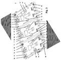
- Die Erfindung wird nachstehend an Hand der in der Zeichnung dargestellten Ausführungsbeispiele näher erläutert. Es zeigen:
- Fig. 1
- einen seitlichen Schnitt durch einen Trägerrahmen mit verstellbaren Wandausgleichselementen,
- Fig. 2
- eine perspektivische Sicht auf die Rückfläche eines Trägerrahmens,
- Fig. 3
- eine perspektivische Sicht auf die Frontfläche eines drei Bedien- oder Funktionselemente aufnehmenden Trägerrahmens,
- Fig. 4
- einen seitlichen Schnitt durch ein aus einem Trägerrahmen und mindestens einem Bedien- oder Funktionselement gebildetes Elektro-Installationsgerät.
- In
Fig. 4 ist ein seitlicher Schnitt durch ein aus einem Trägerrahmen und mindestens einem Bedien- oder Funktionselement gebildetes Elektro-Installationsgerät dargestellt. Bei dem an einer Wand montierbaren Elektro-Installationsgerät 1 handelt es sich vorzugsweise um ein elektronisches Installationsgerät, d. h. um eine Sensoreinheit (Bedieneinheit für Stellvorgänge, Eingabegerät, Tastsensoreinheit) eines Installationsbusses der Gebäudesystemtechnik oder um eine Sensoreinheit zum direkten Steuern/Schalten einer Last (Gebiet der konventionellen Installationstechnik). Dabei kann der Trägerrahmen 3 mehrere Bedienelemente oder Funktionselemente 21 - wie z. B. Einfach-Taster, Mehrfach-Taster, Drehelement, Dreh-Drückelement, Joystick, Touchscreen, Lautsprecher, Mikrofon - aufweisen, welche auf mindestens einen (nicht dargestellten) Unterputz(UP)-Einsatz (= Basiseinheit bzw. Basisgerät) wirken. Mit diesem UP-Einsatz können entweder Lasten direkt (konventionelle Installationstechnik) oder über einen Bus (Gebäudesystemtechnik) gesteuert werden. - Das Trägerrahmenkonzept bietet auch die Möglichkeit, mehrere UP-Einsätze miteinander zu kombinieren. In der konventionellen Installationstechnik ist damit z. B. die Kombination von verschiedenen UP-Geräten - z. B. Dimmer, Schalter oder Jalousieschalter - realisierbar. In der Gebäudesystemtechnik können damit neben einem UP-Busankoppler auch zusätzliche UP-Aktoren über den Trägerrahmen bzw. über im Trägerrahmen integrierte Bauelemente angesteuert werden, welche direkt Lasten schalten oder dimmen können.
- Der Trägerrahmen 3 hat quasi die Funktion eines Verbindungselementes zwischen einem in einer handelsüblichen UP-Gerätedose montierten Basisgerät und dem mindestens einen Bedien- oder Funktionselement 21 und wird an einer Wand montiert. Die Befestigung des Bedien- oder Funktionselementes 21 am Trägerahmen 3 erfolgt, indem eine Nase 23 des Bedien- oder Funktionselementes 21 in einen Hinterschnitt 9 des Trägerrahmens 3 eingreift sowie ein Rasthaken 24 des Bedien- oder Funktionselementes 21 und ein federbelastetes Verriegelungselement 10 des Trägerrahmens 3 arretierend ineinander greifen.
-
Fig. 4 zeigt des Weiteren eine Stirnwand 7 des Trägerahmens 3, welche den zwischen Trägerrahmen 3 und Bedien- oder Funktionselement 21 gebildeten Innenraum umschließt. Spezifische Bedieneinheiten oder Funktionseinheiten sind in einer Frontfläche 22 des Bedien- oder Funktionselementes 21 eingebaut / vorgesehen. - In
Fig. 1 ist ein seitlicher Schnitt durch einen Trägerrahmen mit verstellbaren Wandausgleichselementen dargestellt. Wie zu erkennen ist, bildet sich auf Grund einer Wandunebenheit bei Montage des Trägerrahmens 3 an einer Wand 26 ein Spalt 27 zwischen Rückfläche 6 des Trägerrahmens 3 und der Wand 26 aus. Zum Ausgleich derartiger sich aufgrund von Wandunebenheiten ausbildender Spalte 27 ist der Trägerahmen 3 mit mehreren Wandausgleichelementen 16 bestückt, welche zylinderförmig ausgebildet sind, mantelseitig mit einem Außengewinde 17 versehen sind und an ihren beiden Stirnflächen jeweils Werkzeug-Eingriffsflächen 18, 19 aufweisen, wobei die Werkzeug-Eingriffsfläche 18 von der Frontfläche des Trägerrahmens 3 her und die Werkzeug-Eingriffsfläche 19 von der Rückfläche 6 des Trägerrahmens 3 her zugänglich ist. - Die Werkzeug-Eingriffsflächen 18, 19 sind dabei beispielsweise derart ausgebildet, dass ein Schlitzschraubendreher oder ein Kreuzschlitzschraubendreher oder ein Sechskantschraubendreher (mit Außen- oder Innensechskantkopf respektive Inbus) oder ein Torx-Schraubendreher als Hilfswerkzeug verwendbar ist. Ein besonderer Vorteil der vorgeschlagenen Wandausgleichselemente 16 ist darin zu sehen, dass ein stufenloser Spaltausgleich durch entsprechende Drehung der Wanddausgleichelemente 16 erfolgen kann.
- In
Fig. 2 ist eine perspektivische Sicht auf die Rückfläche 6 eines Trägerrahmens 3 dargestellt, wobei ein Feld eines beispielsweise drei Felder aufweisenden Trägerrahmens 3 gezeigt ist. Unter der "Rückfläche 6" wird die bei Montage des Trägerrahmens 3 der Wand 26 zugewandte Fläche des Trägerrahmens 3 verstanden. Es sind vier Wandausgleichselemente 16 zu erkennen, welche jeweils in an den vier Ecken des Feldes angeordneten Gewindebohrungen 13 des Trägerrahmens einzuschrauben sind. Bei einem der Wandausgleichselemente 16 sind das Außengewinde 17 und die Werkzeug-Eingriffsfläche 19 bezeichnet. - In der Nähe einer jeden Ecke des Feldes ist des Weiteren eine Öffnung 11 angeordnet, welche für eine direkte Wandverschraubung des Trägerrahmens 3 an der Wand 26 geeignet ist, wozu beispielsweise Montageschrauben durch diese Öffnungen 11 in Dübel eingreifen, welche in der Wand 26 eingelassen sind. Zwei weitere Öffnungen 12 dienen zur Verschraubung des Trägerrahmens 3 an einem UP-Einsatz (Basisgerät), wozu Montageschrauben durch diese Öffnungen in Gewindebohrungen einer UP-Gerätedose eingreifen. Dabei ist abschnittsweise um die beiden Öffnungen 12 jeweils ein Freischnitt 14 in den Trägerrahmen 3 eingebracht. Die Enden dieser Freischnitte 14 münden jeweils in Bohrungen, deren Durchmesser größer als die Breites eines Freischnittes 14 ist.
- Durch diese Freischnitte 14 wird verhindert, dass sich bei Unebenheiten der Wand 26 oder bei nicht eben in der Wand 26 eingelassener UP-Gerätedose und gleichzeitig starkem Anziehen des Trägerrahmens 3 an die UP-Gerätedose eine Durchbiegung des Trägerrahmens 3 einstellt, zumindest wird eine derartige Durchbiegung stark reduziert. Es stellt sich lediglich eine Abbiegung der durch die Einschnitte 14 gebildeten relativ kleinen Teilabschnitte des Trägerrahmens gegenüber den Hauptabschnitten des Trägerrahmens ein. Die endseitigen Bohrungen der Freischnitte 14 stellen sicher, dass sich bei Abbiegung der Teilabschnitte keine Spannungsrisse im Trägerrahmen an den Enden der Freischnitte ergeben. Vorteilhaft kann der Trägerrahmen 3 sehr steif ausgebildet werden, da Biegespannungen durch die Freischnitte 14 aufgefangen werden.
- In
Fig. 3 ist eine perspektivische Sicht auf die Frontfläche 5 eines drei Bedien- oder Funktionselemente aufnehmenden Trägerrahmens 3 dargestellt. Unter der "Frontfläche 5" wird die den Bedien- oder Funktionselementen zugewandte Fläche des Trägerrahmens 3 verstanden. Der Trägerrahmen 3 ist allseitig von der Stirnwand 7 umgeben. Es sind drei im Wesentlichen gleichartig ausgebildete Felder 4 für Bedien- oder Funktionsfelder zu erkennen, - wobei die beiden äußeren Felder 4 in ihren Ecken jeweils Gewindebohrungen 13 zum Eindrehen von Wandausgleichselementen 16 aufweisen,
- wobei jedes Feld 4 zwei Öffnungen 12 für die Verschraubung an einem UP-Einsatz aufweist,
- wobei jede dieser Öffnungen 12 teilweise von einem Freischnitt 14 umgeben ist,
- wobei das mittlere Feld 4 an seinen Ecken je eine Öffnung 11 für eine direkte Wandverschraubung aufweist,
- wobei die beiden äußeren Felder 4 an ihren äußeren Ecken je eine Öffnung 11 für eine direkte Wandverschraubung aufweisen,
- wobei jedem Feld 4 ein querbewegliches Verriegelungselement 10 zur Befestigung eines Bedien- oder Funktionselementes zugeordnet ist,
- wobei jedes Feld 4 zwei Kontaktierungsstecker 8 für die elektrische Verbindung mit korrespondierenden, aufzusteckenden Kontaktierungsbuchsen der Bedien- oder Funktionselemente aufweist.
- Selbstverständlich kann der Trägerrahmen 3 auch weniger oder mehr Felder 4 zur Aufnahme von weniger oder mehr Bedien- oder Funktionselemente aufweisen.
- Für die Montage eines Elektro-Installationsgerätes an einer Wand 26 wird zunächst vorausgesetzt, dass mindestens eine UP-Gerätedose an gewünschter Stelle in der Wand eingebracht ist, in welche ein Basisgerät respektive UP-Einsatz zu montieren ist. Nun kann die Montage des Trägerrahmens 3 am Basisgerät respektive UP-Einsatz mittels durch die Öffnungen 12 geführter Schrauben und / oder an der Wand 26 selbst mittels durch einige der Öffnungen 11 geführter und in der Wand (beispielsweise unter Einsatz von Dübeln) verankerter Schrauben erfolgen. Wandunebenheiten zwischen der Rückfläche 6 des Trägerrahmens 3 und der Wand 26 werden durch entsprechendes Eindrehen der Wandausgleichelemente 16 in die Gewindebohrungen 13 ausgeglichen, so dass der Trägerrahmen 3 trotz sich gegebenenfalls aufgrund von Unebenheiten zwischen Rückfläche 6 und Wand 26 ausbildender Spalten 27 fest und ohne Durchbiegungen an der Wand 26 montiert ist.
- Für die Montage eines Bedien- oder Funktionselementes am Trägerrahmen 3 wird zunächst der erste Abschnitt des Bedien- oder Funktionselementes in den Trägerrahmen 3 eingeschwenkt, so dass die Nase 23 unter den Hinterschnitt 9 greift. Anschließend erfolgt durch Druck auf den zweiten Abschnitt des Bedien- oder Funktionselementes eine Verrastung zwischen dem Verriegelungselement 10 und dem Rasthaken 24. Gleichzeitig wird auch die elektrische Kontaktierung zwischen den Kontaktierungssteckern 8 und den korrespondierenden Kontaktierungsbuchsen bewirkt. Für die Montage eines Bedien- oder Funktionselementes am Trägerrahmen 3 ist es von besonderer Wichtigkeit, dass der Trägerrahmen 3 auch bei Wandunebenheiten frei von Durchbiegungen an der Wand 26 montiert ist.
-
- 1
- Elektro-Installationsgerät
- 2
- -
- 3
- Trägerrahmen
- 4
- Feld für Bedien- oder Funktionselement
- 5
- Frontfläche
- 6
- Rückfläche
- 7
- Stirnwand
- 8
- Kontaktierungsstecker
- 9
- Hinterschnitt
- 10
- Verriegelungselement
- 11
- Öffnung für direkte Wandverschraubung
- 12
- Öffnung für Verschraubung an UP-Einsatz
- 13
- Gewindebohrung zum Einschrauben eines Wandausgleichselement
- 14
- Freischnitt
- 15
- -
- 16
- Wandausgleichselement
- 17
- Außengewinde
- 18
- Werkzeug-Eingriffsfläche von der Frontfläche her
- 19
- Werkzeug-Eingriffsfläche von der Rückfläche her
- 20
- -
- 21
- Bedien- oder Funktionselement
- 22
- Frontfläche mit Bedieneinheit und Funktionseinheit
- 23
- Nase
- 24
- Rasthaken
- 25
- -
- 26
- Wand
- 27
- Spalt zwischen Rückfläche des Trägerrahmens und Wand
Claims (4)
- Elektro-Installationsgerät (1) mit mindestens einem in einer handelsüblichen UP-Gerätedose montierbaren Basisgerät, welches über einen Trägerrahmen (3) mit mindestens einem Bedien- oder Funktionselement (21) verbindbar ist, dadurch gekennzeichnet, dass zumindest in den vier Eckbereichen durchgängig von der Frontfläche (6) bis zu der Rückfläche (6) des Trägerahmens (3) Gewindebohrungen (13) zum Einschrauben von Wandausgleichselementen (16) eingebracht sind, wobei Letztere jeweils ein diesen Gewindebohrungen (13) entsprechendes Außengewinde (17) und eine von der Frontfläche her zugängliche Werkzeug-Eingriffsfläche (18) für das Eindrehen / Herausdrehen dieser Wandausgleichselemente (16) aufweisen.
- Elektro-Installationsgerät nach Anspruch 1, dadurch gekennzeichnet, dass die Wandausgleichselemente (16) an beiden Stirnseiten Werkzeug-Eingriffsflächen (18, 19) für das Eindrehen / Herausdrehen aufweisen.
- Elektro-Installationsgerät nach Anspruch 1 oder 2, dadurch gekennzeichnet, dass zwei Öffnungen (12) zur Verschraubung des Trägerrahmens (3) am Basisgerät vorgesehen sind, wobei abschnittsweise um diese beiden Öffnungen (12) jeweils ein Freischnitt (14) in den Trägerrahmen (3) eingebracht ist, wodurch sich abbiegbare Teilabschnitte des Trägerrahmens (3) gegenüber den Hauptabschnitten des Trägerrahmens ergeben.
- Elektro-Installationsgerät nach Anspruch 3, dadurch gekennzeichnet, dass durch endseitige Bohrungen in den Freischnitten (14) sichergestellt ist, dass sich bei Abbiegung der Teilabschnitte keine Spannungsrisse im Trägerrahmen (3) an den Enden der Freischnitte (14) ergeben.
Applications Claiming Priority (1)
| Application Number | Priority Date | Filing Date | Title |
|---|---|---|---|
| DE102009049711A DE102009049711A1 (de) | 2009-10-17 | 2009-10-17 | Elektro-Installationsgerät mit Trägerrahmen und Wandausgleichselementen |
Publications (3)
| Publication Number | Publication Date |
|---|---|
| EP2312714A2 EP2312714A2 (de) | 2011-04-20 |
| EP2312714A3 EP2312714A3 (de) | 2012-11-07 |
| EP2312714B1 true EP2312714B1 (de) | 2016-04-06 |
Family
ID=43558186
Family Applications (1)
| Application Number | Title | Priority Date | Filing Date |
|---|---|---|---|
| EP10179986.4A Active EP2312714B1 (de) | 2009-10-17 | 2010-09-27 | Elektro-Installationsgerät mit Trägerrahmen und Wandausgleichselementen |
Country Status (4)
| Country | Link |
|---|---|
| EP (1) | EP2312714B1 (de) |
| CN (1) | CN102064504B (de) |
| DE (1) | DE102009049711A1 (de) |
| ES (1) | ES2581453T3 (de) |
Families Citing this family (5)
| Publication number | Priority date | Publication date | Assignee | Title |
|---|---|---|---|---|
| DE102020203794A1 (de) | 2020-03-24 | 2021-09-30 | Hansgrohe Se | Wandeinbau-Anschlussboxeinheit mit Funktionsflächenkörper |
| DE102020203800A1 (de) | 2020-03-24 | 2021-09-30 | Hansgrohe Se | Sanitäre Wandeinbau-Anschlussboxeinheit mit elektrischer Leitungsdurchführung |
| DE102020203797A1 (de) | 2020-03-24 | 2021-09-30 | Hansgrohe Se | Wandeinbau-Anschlussboxeinheit mit Verlängerungshülse |
| DE102020203792A1 (de) | 2020-03-24 | 2021-09-30 | Hansgrohe Se | Wandeinbau-Anschlussboxeinheit |
| DE102022132347A1 (de) * | 2022-12-06 | 2024-06-06 | Holoplot Gmbh | Montagesystem für modular aufgebaute, elektronisch steuerbare Schallwandlersysteme |
Family Cites Families (5)
| Publication number | Priority date | Publication date | Assignee | Title |
|---|---|---|---|---|
| GB102404A (en) * | 1916-02-11 | 1916-12-07 | Albert Edward Read | Improvements in or connected with Wall Boxes for Containing Electrical Switches, Plugs and the like. |
| GB519413A (en) * | 1939-06-21 | 1940-03-26 | Charles Francis Bell | Improvements relating to flush-fitting electrical devices |
| CN2344903Y (zh) * | 1998-11-17 | 1999-10-20 | 朱念祖 | 一种终端组合电器箱 |
| DE10200939B4 (de) * | 2002-01-12 | 2018-11-08 | Merten Gmbh & Co. Kg | Elektrisches Installationsgerät |
| DE102007051781B3 (de) | 2007-10-30 | 2009-02-19 | Abb Ag | Installationsgerät mit Trägerrahmen |
-
2009
- 2009-10-17 DE DE102009049711A patent/DE102009049711A1/de not_active Ceased
-
2010
- 2010-09-27 ES ES10179986.4T patent/ES2581453T3/es active Active
- 2010-09-27 EP EP10179986.4A patent/EP2312714B1/de active Active
- 2010-10-15 CN CN201010522102.1A patent/CN102064504B/zh not_active Expired - Fee Related
Also Published As
| Publication number | Publication date |
|---|---|
| EP2312714A3 (de) | 2012-11-07 |
| DE102009049711A1 (de) | 2011-04-21 |
| CN102064504B (zh) | 2016-01-20 |
| EP2312714A2 (de) | 2011-04-20 |
| CN102064504A (zh) | 2011-05-18 |
| ES2581453T3 (es) | 2016-09-05 |
Similar Documents
| Publication | Publication Date | Title |
|---|---|---|
| EP2873792B1 (de) | Türband | |
| EP2642893B1 (de) | Möbelbeschlag zur frontblendenbefestigung | |
| EP1135616A1 (de) | T-verbindung zweier profilstäbe | |
| EP4092351B1 (de) | Dachhaken zur befestigung von auflageelementen mit einer dachkonstruktion, sowie montageverfahren | |
| EP2813783A1 (de) | Ständer zum Abstützen von Solarpaneelen auf einem Flachdach | |
| EP2312714A2 (de) | Elektro-Installationsgerät mit Trägerrahmen und Wandausgleichselementen | |
| EP2749726B1 (de) | Befestigungsvorrichtung für ein Aussteifungselement eines Rollladenkastens | |
| EP1160411B1 (de) | Klemmprofil für eine Glasscheibe | |
| EP0658666A1 (de) | Befestigungssystem für Fassadenplatten | |
| WO2018024448A1 (de) | System zum aufbauen von rahmen | |
| EP1439269B1 (de) | Verbinder für die Befestigung von Montageprofilen der Sanitärtechnik sowie Traggestell mit einem solchen Verbinder | |
| DE102012016634B4 (de) | Zuganker | |
| EP3461984A1 (de) | Eck- und/oder stossverbindung | |
| EP2656461A1 (de) | Trockenbauwand | |
| DE102010037831A1 (de) | Befestigungsvorrichtung an einem Gebäude | |
| EP2425066B1 (de) | Trennwandsystem für den Innenausbau | |
| DE102007051781B3 (de) | Installationsgerät mit Trägerrahmen | |
| EP2788210A1 (de) | Trägerbauteil für einen kraftfahrzeug-fensterheber mit versteifungsstruktur | |
| AT413583B (de) | Stabilisierungsvorrichtung für möbelteile | |
| EP2455559B1 (de) | Dichtung | |
| EP3798383B1 (de) | Haltevorrichtung und verfahren zur herstellung einer fassade | |
| EP4474658B1 (de) | Wandankeranordnung | |
| CH684491A5 (de) | Doppelbodenstütze. | |
| EP3808916B1 (de) | Wandanschlussanordnung für eine überdachungsvorrichtung, verfahren zur herstellung einer wandanschlussanordnung, verwendung eines nutensteins und überdachungsvorrichtung | |
| DE20203512U1 (de) | Rahmensystemanordnung |
Legal Events
| Date | Code | Title | Description |
|---|---|---|---|
| PUAI | Public reference made under article 153(3) epc to a published international application that has entered the european phase |
Free format text: ORIGINAL CODE: 0009012 |
|
| AK | Designated contracting states |
Kind code of ref document: A2 Designated state(s): AL AT BE BG CH CY CZ DE DK EE ES FI FR GB GR HR HU IE IS IT LI LT LU LV MC MK MT NL NO PL PT RO SE SI SK SM TR |
|
| AX | Request for extension of the european patent |
Extension state: BA ME RS |
|
| PUAL | Search report despatched |
Free format text: ORIGINAL CODE: 0009013 |
|
| AK | Designated contracting states |
Kind code of ref document: A3 Designated state(s): AL AT BE BG CH CY CZ DE DK EE ES FI FR GB GR HR HU IE IS IT LI LT LU LV MC MK MT NL NO PL PT RO SE SI SK SM TR |
|
| AX | Request for extension of the european patent |
Extension state: BA ME RS |
|
| RIC1 | Information provided on ipc code assigned before grant |
Ipc: H02G 3/12 20060101AFI20121003BHEP Ipc: H02G 3/14 20060101ALI20121003BHEP |
|
| 17P | Request for examination filed |
Effective date: 20130417 |
|
| GRAP | Despatch of communication of intention to grant a patent |
Free format text: ORIGINAL CODE: EPIDOSNIGR1 |
|
| INTG | Intention to grant announced |
Effective date: 20160105 |
|
| GRAS | Grant fee paid |
Free format text: ORIGINAL CODE: EPIDOSNIGR3 |
|
| GRAA | (expected) grant |
Free format text: ORIGINAL CODE: 0009210 |
|
| AK | Designated contracting states |
Kind code of ref document: B1 Designated state(s): AL AT BE BG CH CY CZ DE DK EE ES FI FR GB GR HR HU IE IS IT LI LT LU LV MC MK MT NL NO PL PT RO SE SI SK SM TR |
|
| REG | Reference to a national code |
Ref country code: GB Ref legal event code: FG4D Free format text: NOT ENGLISH |
|
| REG | Reference to a national code |
Ref country code: AT Ref legal event code: REF Ref document number: 788698 Country of ref document: AT Kind code of ref document: T Effective date: 20160415 Ref country code: CH Ref legal event code: EP |
|
| REG | Reference to a national code |
Ref country code: IE Ref legal event code: FG4D Free format text: LANGUAGE OF EP DOCUMENT: GERMAN |
|
| REG | Reference to a national code |
Ref country code: DE Ref legal event code: R096 Ref document number: 502010011387 Country of ref document: DE |
|
| REG | Reference to a national code |
Ref country code: NL Ref legal event code: FP |
|
| REG | Reference to a national code |
Ref country code: LT Ref legal event code: MG4D |
|
| REG | Reference to a national code |
Ref country code: ES Ref legal event code: FG2A Ref document number: 2581453 Country of ref document: ES Kind code of ref document: T3 Effective date: 20160905 |
|
| REG | Reference to a national code |
Ref country code: FR Ref legal event code: PLFP Year of fee payment: 7 |
|
| PG25 | Lapsed in a contracting state [announced via postgrant information from national office to epo] |
Ref country code: PL Free format text: LAPSE BECAUSE OF FAILURE TO SUBMIT A TRANSLATION OF THE DESCRIPTION OR TO PAY THE FEE WITHIN THE PRESCRIBED TIME-LIMIT Effective date: 20160406 Ref country code: NO Free format text: LAPSE BECAUSE OF FAILURE TO SUBMIT A TRANSLATION OF THE DESCRIPTION OR TO PAY THE FEE WITHIN THE PRESCRIBED TIME-LIMIT Effective date: 20160706 Ref country code: LT Free format text: LAPSE BECAUSE OF FAILURE TO SUBMIT A TRANSLATION OF THE DESCRIPTION OR TO PAY THE FEE WITHIN THE PRESCRIBED TIME-LIMIT Effective date: 20160406 Ref country code: IS Free format text: LAPSE BECAUSE OF FAILURE TO SUBMIT A TRANSLATION OF THE DESCRIPTION OR TO PAY THE FEE WITHIN THE PRESCRIBED TIME-LIMIT Effective date: 20160806 |
|
| PG25 | Lapsed in a contracting state [announced via postgrant information from national office to epo] |
Ref country code: HR Free format text: LAPSE BECAUSE OF FAILURE TO SUBMIT A TRANSLATION OF THE DESCRIPTION OR TO PAY THE FEE WITHIN THE PRESCRIBED TIME-LIMIT Effective date: 20160406 Ref country code: SE Free format text: LAPSE BECAUSE OF FAILURE TO SUBMIT A TRANSLATION OF THE DESCRIPTION OR TO PAY THE FEE WITHIN THE PRESCRIBED TIME-LIMIT Effective date: 20160406 Ref country code: PT Free format text: LAPSE BECAUSE OF FAILURE TO SUBMIT A TRANSLATION OF THE DESCRIPTION OR TO PAY THE FEE WITHIN THE PRESCRIBED TIME-LIMIT Effective date: 20160808 Ref country code: LV Free format text: LAPSE BECAUSE OF FAILURE TO SUBMIT A TRANSLATION OF THE DESCRIPTION OR TO PAY THE FEE WITHIN THE PRESCRIBED TIME-LIMIT Effective date: 20160406 Ref country code: GR Free format text: LAPSE BECAUSE OF FAILURE TO SUBMIT A TRANSLATION OF THE DESCRIPTION OR TO PAY THE FEE WITHIN THE PRESCRIBED TIME-LIMIT Effective date: 20160707 |
|
| REG | Reference to a national code |
Ref country code: DE Ref legal event code: R097 Ref document number: 502010011387 Country of ref document: DE |
|
| PG25 | Lapsed in a contracting state [announced via postgrant information from national office to epo] |
Ref country code: RO Free format text: LAPSE BECAUSE OF FAILURE TO SUBMIT A TRANSLATION OF THE DESCRIPTION OR TO PAY THE FEE WITHIN THE PRESCRIBED TIME-LIMIT Effective date: 20160406 Ref country code: SK Free format text: LAPSE BECAUSE OF FAILURE TO SUBMIT A TRANSLATION OF THE DESCRIPTION OR TO PAY THE FEE WITHIN THE PRESCRIBED TIME-LIMIT Effective date: 20160406 Ref country code: DK Free format text: LAPSE BECAUSE OF FAILURE TO SUBMIT A TRANSLATION OF THE DESCRIPTION OR TO PAY THE FEE WITHIN THE PRESCRIBED TIME-LIMIT Effective date: 20160406 Ref country code: EE Free format text: LAPSE BECAUSE OF FAILURE TO SUBMIT A TRANSLATION OF THE DESCRIPTION OR TO PAY THE FEE WITHIN THE PRESCRIBED TIME-LIMIT Effective date: 20160406 |
|
| PLBE | No opposition filed within time limit |
Free format text: ORIGINAL CODE: 0009261 |
|
| STAA | Information on the status of an ep patent application or granted ep patent |
Free format text: STATUS: NO OPPOSITION FILED WITHIN TIME LIMIT |
|
| PG25 | Lapsed in a contracting state [announced via postgrant information from national office to epo] |
Ref country code: SM Free format text: LAPSE BECAUSE OF FAILURE TO SUBMIT A TRANSLATION OF THE DESCRIPTION OR TO PAY THE FEE WITHIN THE PRESCRIBED TIME-LIMIT Effective date: 20160406 |
|
| 26N | No opposition filed |
Effective date: 20170110 |
|
| PG25 | Lapsed in a contracting state [announced via postgrant information from national office to epo] |
Ref country code: MC Free format text: LAPSE BECAUSE OF FAILURE TO SUBMIT A TRANSLATION OF THE DESCRIPTION OR TO PAY THE FEE WITHIN THE PRESCRIBED TIME-LIMIT Effective date: 20160406 |
|
| PG25 | Lapsed in a contracting state [announced via postgrant information from national office to epo] |
Ref country code: SI Free format text: LAPSE BECAUSE OF FAILURE TO SUBMIT A TRANSLATION OF THE DESCRIPTION OR TO PAY THE FEE WITHIN THE PRESCRIBED TIME-LIMIT Effective date: 20160406 |
|
| REG | Reference to a national code |
Ref country code: IE Ref legal event code: MM4A |
|
| PG25 | Lapsed in a contracting state [announced via postgrant information from national office to epo] |
Ref country code: IE Free format text: LAPSE BECAUSE OF NON-PAYMENT OF DUE FEES Effective date: 20160927 |
|
| PG25 | Lapsed in a contracting state [announced via postgrant information from national office to epo] |
Ref country code: LU Free format text: LAPSE BECAUSE OF NON-PAYMENT OF DUE FEES Effective date: 20160927 |
|
| REG | Reference to a national code |
Ref country code: FR Ref legal event code: PLFP Year of fee payment: 8 |
|
| PG25 | Lapsed in a contracting state [announced via postgrant information from national office to epo] |
Ref country code: CY Free format text: LAPSE BECAUSE OF FAILURE TO SUBMIT A TRANSLATION OF THE DESCRIPTION OR TO PAY THE FEE WITHIN THE PRESCRIBED TIME-LIMIT Effective date: 20160406 Ref country code: HU Free format text: LAPSE BECAUSE OF FAILURE TO SUBMIT A TRANSLATION OF THE DESCRIPTION OR TO PAY THE FEE WITHIN THE PRESCRIBED TIME-LIMIT; INVALID AB INITIO Effective date: 20100927 |
|
| PG25 | Lapsed in a contracting state [announced via postgrant information from national office to epo] |
Ref country code: MT Free format text: LAPSE BECAUSE OF FAILURE TO SUBMIT A TRANSLATION OF THE DESCRIPTION OR TO PAY THE FEE WITHIN THE PRESCRIBED TIME-LIMIT Effective date: 20160406 Ref country code: TR Free format text: LAPSE BECAUSE OF FAILURE TO SUBMIT A TRANSLATION OF THE DESCRIPTION OR TO PAY THE FEE WITHIN THE PRESCRIBED TIME-LIMIT Effective date: 20160406 Ref country code: MK Free format text: LAPSE BECAUSE OF FAILURE TO SUBMIT A TRANSLATION OF THE DESCRIPTION OR TO PAY THE FEE WITHIN THE PRESCRIBED TIME-LIMIT Effective date: 20160406 |
|
| PG25 | Lapsed in a contracting state [announced via postgrant information from national office to epo] |
Ref country code: BG Free format text: LAPSE BECAUSE OF FAILURE TO SUBMIT A TRANSLATION OF THE DESCRIPTION OR TO PAY THE FEE WITHIN THE PRESCRIBED TIME-LIMIT Effective date: 20160406 |
|
| REG | Reference to a national code |
Ref country code: FR Ref legal event code: PLFP Year of fee payment: 9 |
|
| PG25 | Lapsed in a contracting state [announced via postgrant information from national office to epo] |
Ref country code: AL Free format text: LAPSE BECAUSE OF FAILURE TO SUBMIT A TRANSLATION OF THE DESCRIPTION OR TO PAY THE FEE WITHIN THE PRESCRIBED TIME-LIMIT Effective date: 20160406 |
|
| PGFP | Annual fee paid to national office [announced via postgrant information from national office to epo] |
Ref country code: IT Payment date: 20180711 Year of fee payment: 19 Ref country code: FR Payment date: 20180925 Year of fee payment: 9 |
|
| PGFP | Annual fee paid to national office [announced via postgrant information from national office to epo] |
Ref country code: FI Payment date: 20180920 Year of fee payment: 9 Ref country code: CH Payment date: 20180919 Year of fee payment: 9 Ref country code: GB Payment date: 20180919 Year of fee payment: 9 Ref country code: BE Payment date: 20180919 Year of fee payment: 9 |
|
| PGFP | Annual fee paid to national office [announced via postgrant information from national office to epo] |
Ref country code: ES Payment date: 20181022 Year of fee payment: 9 |
|
| REG | Reference to a national code |
Ref country code: ES Ref legal event code: PC2A Owner name: ABB SCHWEIZ AG Effective date: 20190529 |
|
| REG | Reference to a national code |
Ref country code: CH Ref legal event code: PUE Owner name: ABB SCHWEIZ AG, CH Free format text: FORMER OWNER: ABB AG, DE |
|
| REG | Reference to a national code |
Ref country code: GB Ref legal event code: 732E Free format text: REGISTERED BETWEEN 20190718 AND 20190724 |
|
| REG | Reference to a national code |
Ref country code: BE Ref legal event code: PD Owner name: ABB SCHWEIZ AG; CH Free format text: DETAILS ASSIGNMENT: CHANGE OF OWNER(S), CESSION; FORMER OWNER NAME: ABB AG Effective date: 20190702 |
|
| REG | Reference to a national code |
Ref country code: NL Ref legal event code: PD Owner name: ABB SCHWEIZ AG; CH Free format text: DETAILS ASSIGNMENT: CHANGE OF OWNER(S), ASSIGNMENT; FORMER OWNER NAME: ABB AG Effective date: 20190926 |
|
| REG | Reference to a national code |
Ref country code: AT Ref legal event code: PC Ref document number: 788698 Country of ref document: AT Kind code of ref document: T Owner name: ABB SCHWEIZ AG, CH Effective date: 20190829 |
|
| REG | Reference to a national code |
Ref country code: DE Ref legal event code: R081 Ref document number: 502010011387 Country of ref document: DE Owner name: ABB SCHWEIZ AG, CH Free format text: FORMER OWNER: ABB AG, 68309 MANNHEIM, DE |
|
| REG | Reference to a national code |
Ref country code: FI Ref legal event code: MAE |
|
| PG25 | Lapsed in a contracting state [announced via postgrant information from national office to epo] |
Ref country code: FI Free format text: LAPSE BECAUSE OF NON-PAYMENT OF DUE FEES Effective date: 20190927 |
|
| PG25 | Lapsed in a contracting state [announced via postgrant information from national office to epo] |
Ref country code: CZ Free format text: LAPSE BECAUSE OF NON-PAYMENT OF DUE FEES Effective date: 20190927 |
|
| REG | Reference to a national code |
Ref country code: CH Ref legal event code: PL |
|
| PG25 | Lapsed in a contracting state [announced via postgrant information from national office to epo] |
Ref country code: CH Free format text: LAPSE BECAUSE OF NON-PAYMENT OF DUE FEES Effective date: 20190930 Ref country code: LI Free format text: LAPSE BECAUSE OF NON-PAYMENT OF DUE FEES Effective date: 20190930 |
|
| REG | Reference to a national code |
Ref country code: BE Ref legal event code: MM Effective date: 20190930 |
|
| PG25 | Lapsed in a contracting state [announced via postgrant information from national office to epo] |
Ref country code: BE Free format text: LAPSE BECAUSE OF NON-PAYMENT OF DUE FEES Effective date: 20190930 Ref country code: IT Free format text: LAPSE BECAUSE OF NON-PAYMENT OF DUE FEES Effective date: 20190927 |
|
| GBPC | Gb: european patent ceased through non-payment of renewal fee |
Effective date: 20190927 |
|
| PG25 | Lapsed in a contracting state [announced via postgrant information from national office to epo] |
Ref country code: GB Free format text: LAPSE BECAUSE OF NON-PAYMENT OF DUE FEES Effective date: 20190927 Ref country code: FR Free format text: LAPSE BECAUSE OF NON-PAYMENT OF DUE FEES Effective date: 20190930 |
|
| REG | Reference to a national code |
Ref country code: ES Ref legal event code: FD2A Effective date: 20210201 |
|
| PG25 | Lapsed in a contracting state [announced via postgrant information from national office to epo] |
Ref country code: ES Free format text: LAPSE BECAUSE OF NON-PAYMENT OF DUE FEES Effective date: 20190928 |
|
| PGFP | Annual fee paid to national office [announced via postgrant information from national office to epo] |
Ref country code: DE Payment date: 20250919 Year of fee payment: 16 |
|
| PGFP | Annual fee paid to national office [announced via postgrant information from national office to epo] |
Ref country code: NL Payment date: 20250918 Year of fee payment: 16 |
|
| PGFP | Annual fee paid to national office [announced via postgrant information from national office to epo] |
Ref country code: AT Payment date: 20250919 Year of fee payment: 16 |