EP2312606B1 - Circuit-breaker with a common housing - Google Patents
Circuit-breaker with a common housing Download PDFInfo
- Publication number
- EP2312606B1 EP2312606B1 EP09012967A EP09012967A EP2312606B1 EP 2312606 B1 EP2312606 B1 EP 2312606B1 EP 09012967 A EP09012967 A EP 09012967A EP 09012967 A EP09012967 A EP 09012967A EP 2312606 B1 EP2312606 B1 EP 2312606B1
- Authority
- EP
- European Patent Office
- Prior art keywords
- circuit breaker
- interrupter insert
- breaker according
- drive rod
- armature
- Prior art date
- Legal status (The legal status is an assumption and is not a legal conclusion. Google has not performed a legal analysis and makes no representation as to the accuracy of the status listed.)
- Not-in-force
Links
- 230000005291 magnetic effect Effects 0.000 claims description 27
- 230000005294 ferromagnetic effect Effects 0.000 claims description 10
- 239000011810 insulating material Substances 0.000 claims description 9
- 239000000463 material Substances 0.000 claims description 4
- 238000002347 injection Methods 0.000 claims description 2
- 239000007924 injection Substances 0.000 claims description 2
- 239000002991 molded plastic Substances 0.000 claims 1
- 238000000034 method Methods 0.000 description 3
- 229910018503 SF6 Inorganic materials 0.000 description 2
- 238000004519 manufacturing process Methods 0.000 description 2
- 239000000243 solution Substances 0.000 description 2
- SFZCNBIFKDRMGX-UHFFFAOYSA-N sulfur hexafluoride Chemical compound FS(F)(F)(F)(F)F SFZCNBIFKDRMGX-UHFFFAOYSA-N 0.000 description 2
- RYGMFSIKBFXOCR-UHFFFAOYSA-N Copper Chemical compound [Cu] RYGMFSIKBFXOCR-UHFFFAOYSA-N 0.000 description 1
- 238000004026 adhesive bonding Methods 0.000 description 1
- 230000005540 biological transmission Effects 0.000 description 1
- 238000010276 construction Methods 0.000 description 1
- 229910052802 copper Inorganic materials 0.000 description 1
- 239000010949 copper Substances 0.000 description 1
- 230000004907 flux Effects 0.000 description 1
- 239000003292 glue Substances 0.000 description 1
- 230000010354 integration Effects 0.000 description 1
- 239000002184 metal Substances 0.000 description 1
- 229910052751 metal Inorganic materials 0.000 description 1
- 239000004033 plastic Substances 0.000 description 1
- 230000003068 static effect Effects 0.000 description 1
- 229960000909 sulfur hexafluoride Drugs 0.000 description 1
- 239000012815 thermoplastic material Substances 0.000 description 1
- 238000003466 welding Methods 0.000 description 1
Images
Classifications
-
- H—ELECTRICITY
- H01—ELECTRIC ELEMENTS
- H01H—ELECTRIC SWITCHES; RELAYS; SELECTORS; EMERGENCY PROTECTIVE DEVICES
- H01H33/00—High-tension or heavy-current switches with arc-extinguishing or arc-preventing means
- H01H33/60—Switches wherein the means for extinguishing or preventing the arc do not include separate means for obtaining or increasing flow of arc-extinguishing fluid
- H01H33/66—Vacuum switches
- H01H33/662—Housings or protective screens
- H01H33/66207—Specific housing details, e.g. sealing, soldering or brazing
-
- H—ELECTRICITY
- H01—ELECTRIC ELEMENTS
- H01H—ELECTRIC SWITCHES; RELAYS; SELECTORS; EMERGENCY PROTECTIVE DEVICES
- H01H33/00—High-tension or heavy-current switches with arc-extinguishing or arc-preventing means
- H01H33/60—Switches wherein the means for extinguishing or preventing the arc do not include separate means for obtaining or increasing flow of arc-extinguishing fluid
- H01H33/66—Vacuum switches
- H01H33/666—Operating arrangements
- H01H33/6662—Operating arrangements using bistable electromagnetic actuators, e.g. linear polarised electromagnetic actuators
-
- H—ELECTRICITY
- H01—ELECTRIC ELEMENTS
- H01H—ELECTRIC SWITCHES; RELAYS; SELECTORS; EMERGENCY PROTECTIVE DEVICES
- H01H33/00—High-tension or heavy-current switches with arc-extinguishing or arc-preventing means
- H01H33/60—Switches wherein the means for extinguishing or preventing the arc do not include separate means for obtaining or increasing flow of arc-extinguishing fluid
- H01H33/66—Vacuum switches
- H01H33/662—Housings or protective screens
- H01H33/66207—Specific housing details, e.g. sealing, soldering or brazing
- H01H2033/6623—Details relating to the encasing or the outside layers of the vacuum switch housings
Definitions
- the present invention relates to a pole part of a circuit-breaker for switching medium-voltage to high-voltage circuits, comprising a cup-shaped housing made of insulating material for accommodating an interrupter insert operated by a drive rod. Furthermore, the invention relates to a circuit-breaker actuated by a bistable electromagnetic actuator and comprising such a pole part.
- the invention is especially focused on the field of medium voltage vacuum circuit breakers.
- these special circuit breakers improve the interruption process substantially through reduced contact travel, reduced contact velocity and small masses for moving the electrical contacts. Accordingly, these vacuum circuit breakers require a significantly smaller, lower energy actuator which is usually designed as an electromagnetic device having at least one electrical coil surrounded by ferromagnetic joke assembly which corresponds with a moveable ferromagnetic armature in order to generate a suitable mechanical actuating force for the interrupter insert of all connected pole parts.
- ferromagnetic joke assembly which corresponds with a moveable ferromagnetic armature in order to generate a suitable mechanical actuating force for the interrupter insert of all connected pole parts.
- three pole parts are needed for a medium voltage circuit breaker of a power grid.
- a medium voltage circuit breaker rated between 1 and 72 kV is mostly assembled into a metal-enclosed switch gear line-up for indoor use, or may be installed outdoor in a substation.
- modern vacuum circuit breakers replace air-brake circuit breakers for indoor applications.
- the characteristics of medium-voltage breakers are given by international standards.
- vacuum circuit breakers rated current up to 300 Ampere.
- breakers interrupt the current by creating and extinguishing the arc in a vacuum container.
- the present invention is not only applicable to vacuum circuit breakers, but also to air circuit breakers or modem SF6 circuit breakers having a chamber filled with sulfurhexafluoride gas.
- the present invention might also be applicable to high-voltage circuit breakers.
- circuit breakers of the kind as mentioned above are mostly equipped with electromagnetic actuators.
- An electromagnetic actuator generally generates a high force density to fast operate the moving contacts of the interrupter inserts.
- For providing a sufficient static holding force for keeping the electrical contacts in the opened or in the closed position a permanent magnetic arrangement is used.
- an integrated electrical coil is feed with electrical energy.
- an electromagnetic actuator is accommodated in an own housing.
- the document JP 56 167222 A discloses a circuit breaker for switching medium-voltage to high-voltage circuits comprising a pole part, with the features in the preamble of claim 1.
- the document EP 0898 780 B1 describes an electromagnetically actuated medium-voltage circuit breaker.
- a single electromagnetic actuator drives a common jackshaft.
- the jackshaft internally couples the actuator force to the moving electrically contacts of each vacuum interrupter on all three pole parts through insulated push rods.
- the electromagnetic actuator consists of a bistable magnet system, in which switching the armature to the relative positions - open or closed - is effected by the magnetic field of an electrically excited coil.
- the magnetic latching requires holding means for the contacts during faults.
- a permanent magnet arrangement holds the ferromagnetic armature in one of said two positions. In the open position the electrical contacts of the vacuum interrupter are opened; in the closed position these electrical contacts are closed.
- All main parts of the circuit breaker need an own housing, especially, the three pole parts comprise a secure insulating housing. Also the operating mechanism and the actuator part are equipped with respective housings which are shaped according to the technical functions of these parts.
- the conventional separate housing solution to realize a mechanical connection between the at least one actuator and the driven pole parts as well as the operating mechanism results in loss of operating stroke due to loose and due to the flexibility of all parts. Additionally, it increases the manufacturing effort of the circuit breaker, both for material and for assembly.
- the document DE 102 38 950 A1 discloses another solution which solve the aforementioned problem by using another arrangement principle of the main parts.
- the actuator part is coaxially arranged to the pole part of the circuit breaker.
- the pole part consists of a housing of plastic material for containing a vacuum interrupter insert.
- the actuator part is housed in a ferromagnetic joke arrangement which surrounds two electrical coils as well as an intermediate permanent magnet for generating the mechanical force of the magnetic actuator.
- the ferromagnetic joke arrangement is necessary in order to lead the magnetic flux which creates the mechanical force in conjunction with the adjacent moveable armature.
- the moveable armature consists of a divided axis rod having a plunger section on each side. One part of the divided axis rod is connected to a drive rod of the interrupter insert. Said drive rod moves the lower electrical contact of the pair of electrical contacts of the interrupter insert. The upper electrical contact is generally fixed, but electrically supported. Between the housing of the pole part and the housing of the magnetic actuator an additional metal plate for grounding purposes is arranged.
- the circuit breaker as described above has a compact design but each main part is provided with its own housing. Especially, the metallic housing of the magnetic actuator assembly which is represented by ferromagnetic joke is exposed. Under security aspects exposed electrical parts are dangerous.
- a medium-voltage to high-voltage circuit-breaker having a special pole part with a cup-shaped housing made of insulating material for accommodating an interrupter insert operated by a drive rod, wherein the cup-shaped housing is divided in an upper housing part in which the interrupter insert is arranged and a lower housing part for accommodating a magnetic actuator, wherein the drive rod of the interrupter insert is coaxially arranged to the armature of the magnetic actuator.
- the present invention proposes a special integration of the magnetic actuator into the pole part.
- the interrupter insert as well as the magnetic actuator and all remaining force transmission parts are inside a common housing made of insulating material. Hence, there is no need for separate housings. Due to the compact design the number of parts is strongly reduced and the assembling time is significantly shorter.
- the axis rod of the magnetic armature is an integral part of the device rod of the interrupter insert in order to achieve a direct and compact connection.
- the axis rod is directly casted into the lower end of an insulating material of the drive rod.
- the axis rod could also screwed in the drive rod in order to attach the armature adjustable relative to the interrupter insert.
- the screw connection between the axis rod and the armature and the drive rod of the interrupter insert should be secured by locking means in order to avoid loosening during the life time. This thread locking can be reached by several ways, especially by using a lock screw on the same thread. Alternatively, one or more small crews could be used at predefined locations into the thread.
- gluing of the thread for permanent locking is possible. This could be realized just by adding glue of ultrasonic welding from outside of the connected parts.
- the thread connection could be also designed in a way that the internal friction is sufficient to hold the actuator in place so that separate locking means are not required.
- the magnetic actuator is placed directly below the interrupter insert in the opening area of the cup shaped housing. Therefore, there is no need for additional mechanical linkage.
- the magnetic actuator is provided with an outside screw thread which corresponds to an inside screw thread on the opening area of the cup-shaped housing.
- the axis rod of the armature of the magnetic actuator is added during the assembly process, it is preferably screwed into the corresponding drive rod of the interrupter insert until the correct position relative to the interrupter insert is reached.
- the electromagnetic actuator preferably comprises one electrical coil for moving the ferromagnetic armature consisting of a lower plunger and an upper plunger connected with the intermediate axis rod.
- the upper plunger of the armature is preferably screwed onto the common axis; then the axis rod is added and finally the lower plunger in order to ensure an easy assembling procedure.
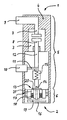
- the figure shows a schematic side view of a medium-voltage circuit-breaker actuated by a bistable electromagnetic actuator for operating a corresponding pole part.
- the medium-voltage circuit breaker as shown in the figure principally consists of a pole part 1 and an electromagnetic actuator 2 which are coaxially arranged one to another.
- the cup-shaped housing 4 is divided in an upper housing part 5 and a lower housing part 6.
- the upper housing part 5 contains the vacuum interrupter insert 3 and its operating means.
- the lower housing part 6 contains the electromagnetic actuator 2.
- the cup-shaped housing 4 consists of a suitable injection molded thermoplastic material.
- the interrupter insert 3 is designed as a vacuum interrupter insert with a vacuum chamber in which a fixed electrical contact 7 and a corresponding moveable electrical contact 8 is arranged. Both electrical contacts 7 and 8 are coaxially arranged on opposite sides of the vacuum chamber.
- the fixed electrical contact 7 is connected to a corresponding electrical terminal 9 made of copper material molded in the housing 1.
- the corresponding electrical contact 8 of the vacuum interrupter insert 3 is moveable connected to a corresponding electrical terminal 10 which is also molded in the housing 1. Between the electrical terminal 10 and the moveable electrical contact 8 an intermediate flexible connector 11 is arranged.
- the vacuum interrupter insert 3 is operated by a drive rod 12 made of insulating material which is coaxially connected to the armature 13 of the magnetic actuator 2.
- An axis rod 14 of the armature 13 is casted into the lower end of the insulating material of the drive rod 12.
- a wipe spring arrangement 15 is integrated in the force flow between the armature 13 of the magnetic actuator 2 and the drive rod 12 of the vacuum interrupter insert 3 .
- the magnetic actuator 2 integrated in the lower housing part 6 of the pole port 1 is placed directly below the interrupter insert 3 in an opening area 16 of the cup-shaped housing 4.
- an outside screw thread 17 is provided thereon which corresponds to an inside screw threat molded in the opening area 16 of the housing 4.
- the screw connection between the magnetic actuator 2 and the housing 4 is secured by - not shown - fixing means.
- the electromagnetic actuator 2 comprises one electrical coil 18 for moving the ferromagnetic armature 13.
- the ferromagnetic armature 13 consists of a lower plunger 19 and an upper plunger 20 which are connected with the axis rod 14 in order to provide a constant distance between the lower plunger 19 and the upper plunger 20.
- the lower plunger 19 is visible from outside in order to indicate the current position of the armature 13 which corresponds with the switching position of the circuit breaker.
- an additional permanent magnet 21 is arranged adjacent to the electrical coil 18 of the electromagnetic actuator 2.
- the electromagnetic actuator 2 provides a bistable switching position for the mechanically connected vacuum interrupter insert 3.
Landscapes
- Physics & Mathematics (AREA)
- Electromagnetism (AREA)
- Electromagnets (AREA)
- Breakers (AREA)
- Driving Mechanisms And Operating Circuits Of Arc-Extinguishing High-Tension Switches (AREA)
Priority Applications (8)
| Application Number | Priority Date | Filing Date | Title |
|---|---|---|---|
| EP09012967A EP2312606B1 (en) | 2009-10-14 | 2009-10-14 | Circuit-breaker with a common housing |
| RU2012119505/07A RU2562133C2 (ru) | 2009-10-14 | 2010-10-14 | Автоматический выключатель с общим корпусом |
| BR112012008801A BR112012008801A2 (pt) | 2009-10-14 | 2010-10-14 | disjuntor com um invólucro comum. |
| PCT/EP2010/006288 WO2011045062A1 (en) | 2009-10-14 | 2010-10-14 | Circuit-breaker with a common housing |
| IN3147DEN2012 IN2012DN03147A (enExample) | 2009-10-14 | 2010-10-14 | |
| CN201080046586.5A CN102687227B (zh) | 2009-10-14 | 2010-10-14 | 具有共用壳体的断路器 |
| UAA201204642A UA108622C2 (ru) | 2009-10-14 | 2010-10-14 | Прерыватель для переключения с контура среднего напряжения на контур ВЫСОКОГО НАПРЯЖЕНИЯ |
| US13/447,910 US20120274428A1 (en) | 2009-10-14 | 2012-04-16 | Circuit-breaker with a common housing |
Applications Claiming Priority (1)
| Application Number | Priority Date | Filing Date | Title |
|---|---|---|---|
| EP09012967A EP2312606B1 (en) | 2009-10-14 | 2009-10-14 | Circuit-breaker with a common housing |
Publications (2)
| Publication Number | Publication Date |
|---|---|
| EP2312606A1 EP2312606A1 (en) | 2011-04-20 |
| EP2312606B1 true EP2312606B1 (en) | 2013-02-27 |
Family
ID=41796509
Family Applications (1)
| Application Number | Title | Priority Date | Filing Date |
|---|---|---|---|
| EP09012967A Not-in-force EP2312606B1 (en) | 2009-10-14 | 2009-10-14 | Circuit-breaker with a common housing |
Country Status (8)
| Country | Link |
|---|---|
| US (1) | US20120274428A1 (enExample) |
| EP (1) | EP2312606B1 (enExample) |
| CN (1) | CN102687227B (enExample) |
| BR (1) | BR112012008801A2 (enExample) |
| IN (1) | IN2012DN03147A (enExample) |
| RU (1) | RU2562133C2 (enExample) |
| UA (1) | UA108622C2 (enExample) |
| WO (1) | WO2011045062A1 (enExample) |
Cited By (6)
| Publication number | Priority date | Publication date | Assignee | Title |
|---|---|---|---|---|
| EP2874169A1 (en) | 2013-11-18 | 2015-05-20 | ABB Technology AG | Actuator for medium voltage switchgear |
| DE102014219772A1 (de) | 2014-09-30 | 2016-03-31 | Siemens Aktiengesellschaft | Vakuumschaltröhre |
| DE102015200135A1 (de) | 2015-01-08 | 2016-07-14 | Siemens Aktiengesellschaft | Kopplungsglied für ein elektrisches Schaltgerät,insbesondere eine Vakuumschaltröhre |
| DE102015200112A1 (de) | 2015-01-08 | 2016-07-14 | Siemens Aktiengesellschaft | Vakuumschaltröhre |
| EP3182436A1 (en) | 2015-12-18 | 2017-06-21 | ABB Schweiz AG | Medium voltage circuit breaker for subsea applications |
| EP3316273B1 (en) * | 2016-10-25 | 2023-11-29 | ABB Schweiz AG | Pole part for medium voltage switchgear |
Families Citing this family (24)
| Publication number | Priority date | Publication date | Assignee | Title |
|---|---|---|---|---|
| EP2407990A1 (en) * | 2010-07-15 | 2012-01-18 | ABB Technology AG | Circuit-breaker pole part and method for producing such a pole part |
| EP2407989A1 (en) * | 2010-07-15 | 2012-01-18 | ABB Technology AG | Method for producing a circuit-breaker pole part |
| EP2460637B1 (en) * | 2010-12-03 | 2013-11-13 | ABB Technology AG | A push rod of a vacuum interrupter and method of manufacturing the same |
| JP5579323B2 (ja) * | 2011-07-07 | 2014-08-27 | 三菱電機株式会社 | 電磁操作装置 |
| US9030280B2 (en) * | 2011-09-19 | 2015-05-12 | Mitsubishi Electric Corporation | Electromagnetically operated device and switching device including the same |
| EP2867909B1 (en) | 2012-06-27 | 2016-04-06 | ABB Technology Ltd. | A high voltage current interrupted and an actuator system for a high voltage current interruptor |
| US20140002215A1 (en) * | 2012-06-29 | 2014-01-02 | Siemens Industry, Inc. | Electrical contact apparatus, assemblies, and methods of operation |
| WO2014093682A1 (en) * | 2012-12-12 | 2014-06-19 | Southern States, Llc | Sealed solenoid magnetically operated high voltage electric power switch |
| JP6216529B2 (ja) * | 2013-03-28 | 2017-10-18 | 株式会社日立産機システム | 鉄道車両 |
| GB2522696A (en) * | 2014-02-03 | 2015-08-05 | Gen Electric | Improvements in or relating to vacuum switching devices |
| DE102014004843A1 (de) * | 2014-04-02 | 2015-10-08 | Schaltbau Gmbh | Gleichstromschütz mit zusätzlicher Schalttauglichkeit für Wechselstromlasten und Polung entgegen der Vorzugsstromrichtung |
| EP3143631B1 (en) * | 2014-05-14 | 2018-05-09 | ABB Schweiz AG | Thomson coil based actuator |
| EP3026689B1 (en) * | 2014-11-27 | 2018-06-27 | Tyco Electronics UK Limited | High voltage circuit breaker, system, vacuum interrupter module, and associated drive module |
| DE102016208274A1 (de) * | 2016-05-13 | 2017-11-16 | Siemens Aktiengesellschaft | Kopplungsglied für ein elektrisches Schaltgerät |
| DE102016208270A1 (de) | 2016-05-13 | 2017-11-16 | Siemens Aktiengesellschaft | Kopplungsglied für ein elektrisches Schaltgerät mit Impulsmasseelement |
| KR101918237B1 (ko) * | 2017-03-28 | 2018-11-13 | 엘에스산전 주식회사 | 고속스위치 |
| RU2686659C1 (ru) * | 2017-06-02 | 2019-04-30 | Дмитрий Валерьевич Хачатуров | Быстродействующее коммутационное устройство |
| US10784064B2 (en) * | 2018-10-12 | 2020-09-22 | S&C Electric Company | Reduced size fault interrupter |
| US10825625B1 (en) * | 2019-06-07 | 2020-11-03 | Smart Wires Inc. | Kinetic actuator for vacuum interrupter |
| US11152174B2 (en) | 2019-06-19 | 2021-10-19 | Eaton Intelligent Power Limited | Dual thomson coil-actuated, double-bellows vacuum circuit interrupter |
| US11107653B2 (en) * | 2019-06-26 | 2021-08-31 | Eaton Intelligent Power Limited | Dual-action switching mechanism and pole unit for circuit breaker |
| GB2585833A (en) * | 2019-07-16 | 2021-01-27 | Eaton Intelligent Power Ltd | Circuit breaker |
| US11183348B1 (en) | 2020-07-21 | 2021-11-23 | Eaton Intelligent Power Limited | Vacuum circuit interrupter with decelerator with integrated latch assembly |
| US12100939B2 (en) * | 2022-04-21 | 2024-09-24 | Jst Power Equipment, Inc. | Circuit breaker with terminal bushings having dynamic seal |
Family Cites Families (27)
| Publication number | Priority date | Publication date | Assignee | Title |
|---|---|---|---|---|
| GB1143805A (enExample) * | 1966-08-04 | |||
| JPS56114234A (en) * | 1980-02-14 | 1981-09-08 | Meidensha Electric Mfg Co Ltd | Vacuum switching device |
| JPS56167222A (en) * | 1980-05-28 | 1981-12-22 | Meidensha Electric Mfg Co Ltd | Vacuum breaker |
| DD226690A1 (de) * | 1984-09-24 | 1985-08-28 | Buchwitz Otto Starkstrom | Schalterpol |
| JPH0277376U (enExample) * | 1988-12-01 | 1990-06-13 | ||
| DE4021945C2 (de) * | 1990-07-10 | 1999-12-30 | Alstom Sachsenwerk Gmbh | Schaltvorrichtung zur Unterbrechung von Fehlerströmen |
| US5208570A (en) * | 1992-04-06 | 1993-05-04 | Caterpillar Inc. | Solenoid construction and method for making same |
| WO1994025973A1 (en) * | 1993-04-29 | 1994-11-10 | Lindsey Manufacturing Company | Integrated electrical system |
| US5513832A (en) * | 1994-04-22 | 1996-05-07 | Lectron Products, Inc. | Variable force solenoid valve |
| US5597992A (en) * | 1994-12-09 | 1997-01-28 | Cooper Industries, Inc. | Current interchange for vacuum capacitor switch |
| DE19619835A1 (de) | 1996-05-17 | 1997-11-20 | E I B S A | Elektrischer Schalter mit einem magnetischen Antrieb |
| JP3441360B2 (ja) * | 1997-03-25 | 2003-09-02 | 株式会社東芝 | しゃ断器の操作装置 |
| JP2000268683A (ja) * | 1999-01-14 | 2000-09-29 | Toshiba Corp | 開閉器の操作装置 |
| US6723940B1 (en) * | 1999-04-13 | 2004-04-20 | Abb Inc. | Encapsulated magnetically actuated vacuum interrupter with integral bushing connector |
| JP4409787B2 (ja) * | 2001-05-01 | 2010-02-03 | 三菱電機株式会社 | 固体絶縁開閉器 |
| US6753493B2 (en) * | 2001-06-01 | 2004-06-22 | Hubbell Incorporated | Electrical circuit interrupting device |
| JP4494673B2 (ja) * | 2001-07-12 | 2010-06-30 | 三菱電機株式会社 | 電力用開閉装置 |
| RU2208862C1 (ru) * | 2001-12-26 | 2003-07-20 | Открытое акционерное общество "АВТОВАЗ" | Электрический выключатель |
| US6747234B2 (en) * | 2002-07-23 | 2004-06-08 | Maysteel Llc | High voltage interrupter |
| DE10238950B4 (de) | 2002-08-24 | 2008-04-10 | Abb Patent Gmbh | Vakuumschaltgerät |
| US6972500B2 (en) * | 2003-03-26 | 2005-12-06 | Keihin Corporation | Electromagnetic actuator |
| JP4403782B2 (ja) * | 2003-11-17 | 2010-01-27 | 株式会社日立製作所 | 真空スイッチギヤ |
| JP4423598B2 (ja) * | 2004-08-17 | 2010-03-03 | 株式会社日立製作所 | 真空スイッチギヤの単相モジュールおよび真空スイッチギヤ |
| CN2724187Y (zh) * | 2004-09-06 | 2005-09-07 | 苏本宽 | 永磁机构真空接触器 |
| EP1707798B1 (en) * | 2005-03-14 | 2010-05-19 | C.R.F. Società Consortile per Azioni | Adjustable metering servovalve for a fuel injector, and relative adjustment method |
| EP1843375B1 (de) * | 2006-04-05 | 2011-07-06 | ABB Technology AG | Elektromagnetischer Aktuator, insbesondere für einen Mittelspannungsschalter |
| DE102007028205A1 (de) * | 2007-06-15 | 2008-12-24 | Siemens Ag | Schaltpol für ein Hochspannungsnetz |
-
2009
- 2009-10-14 EP EP09012967A patent/EP2312606B1/en not_active Not-in-force
-
2010
- 2010-10-14 WO PCT/EP2010/006288 patent/WO2011045062A1/en not_active Ceased
- 2010-10-14 BR BR112012008801A patent/BR112012008801A2/pt not_active IP Right Cessation
- 2010-10-14 UA UAA201204642A patent/UA108622C2/ru unknown
- 2010-10-14 IN IN3147DEN2012 patent/IN2012DN03147A/en unknown
- 2010-10-14 RU RU2012119505/07A patent/RU2562133C2/ru not_active IP Right Cessation
- 2010-10-14 CN CN201080046586.5A patent/CN102687227B/zh not_active Expired - Fee Related
-
2012
- 2012-04-16 US US13/447,910 patent/US20120274428A1/en not_active Abandoned
Cited By (9)
| Publication number | Priority date | Publication date | Assignee | Title |
|---|---|---|---|---|
| EP2874169A1 (en) | 2013-11-18 | 2015-05-20 | ABB Technology AG | Actuator for medium voltage switchgear |
| US9478342B2 (en) | 2013-11-18 | 2016-10-25 | Abb Schweiz Ag | Actuator for medium voltage switchgear |
| DE102014219772A1 (de) | 2014-09-30 | 2016-03-31 | Siemens Aktiengesellschaft | Vakuumschaltröhre |
| WO2016050490A1 (de) | 2014-09-30 | 2016-04-07 | Siemens Aktiengesellschaft | Vakuumschaltröhre |
| DE102015200135A1 (de) | 2015-01-08 | 2016-07-14 | Siemens Aktiengesellschaft | Kopplungsglied für ein elektrisches Schaltgerät,insbesondere eine Vakuumschaltröhre |
| WO2016110430A1 (de) | 2015-01-08 | 2016-07-14 | Siemens Aktiengesellschaft | Kopplungsglied für ein elektrisches schaltgerät, insbesondere eine vakuumschaltröhre |
| DE102015200112A1 (de) | 2015-01-08 | 2016-07-14 | Siemens Aktiengesellschaft | Vakuumschaltröhre |
| EP3182436A1 (en) | 2015-12-18 | 2017-06-21 | ABB Schweiz AG | Medium voltage circuit breaker for subsea applications |
| EP3316273B1 (en) * | 2016-10-25 | 2023-11-29 | ABB Schweiz AG | Pole part for medium voltage switchgear |
Also Published As
| Publication number | Publication date |
|---|---|
| IN2012DN03147A (enExample) | 2015-09-18 |
| CN102687227A (zh) | 2012-09-19 |
| WO2011045062A1 (en) | 2011-04-21 |
| US20120274428A1 (en) | 2012-11-01 |
| RU2562133C2 (ru) | 2015-09-10 |
| BR112012008801A2 (pt) | 2019-09-24 |
| CN102687227B (zh) | 2016-04-13 |
| EP2312606A1 (en) | 2011-04-20 |
| UA108622C2 (ru) | 2015-05-25 |
| RU2012119505A (ru) | 2013-11-20 |
Similar Documents
| Publication | Publication Date | Title |
|---|---|---|
| EP2312606B1 (en) | Circuit-breaker with a common housing | |
| EP2312605B1 (en) | Bistable magnetic actuator for a medium voltage circuit breaker | |
| US8653398B2 (en) | Electrical device with a multi-chamber housing | |
| CN101740260A (zh) | 真空开关设备 | |
| RU2322724C2 (ru) | Электромагнитный привод | |
| US9620316B2 (en) | Circuit-breaker pole part with a flexible conductor for connecting a movable electrical contact | |
| EP2720244A1 (en) | A pole part of a circuit-breaker arrangement with a heat sink element | |
| AU2020396537B2 (en) | Switch assembly with energy harvesting | |
| CN201886957U (zh) | 户内高压交流真空断路器 | |
| US20150114933A1 (en) | Pushrod assembly for a medium voltage vacuum circuit breaker | |
| CN220065545U (zh) | 电气化铁道户外全绝缘断路器 | |
| Ruhland | Vacuum circuit breaker with asymmetrical actuator | |
| CA3117799C (en) | Electromagnetic drive for a power circuit-breaker with a vacuum interrupter | |
| HK1129944A1 (en) | Vacuum insulated switchgear |
Legal Events
| Date | Code | Title | Description |
|---|---|---|---|
| PUAI | Public reference made under article 153(3) epc to a published international application that has entered the european phase |
Free format text: ORIGINAL CODE: 0009012 |
|
| AK | Designated contracting states |
Kind code of ref document: A1 Designated state(s): AT BE BG CH CY CZ DE DK EE ES FI FR GB GR HR HU IE IS IT LI LT LU LV MC MK MT NL NO PL PT RO SE SI SK SM TR |
|
| AX | Request for extension of the european patent |
Extension state: AL BA RS |
|
| 17P | Request for examination filed |
Effective date: 20111020 |
|
| 17Q | First examination report despatched |
Effective date: 20111109 |
|
| RIC1 | Information provided on ipc code assigned before grant |
Ipc: H01H 33/66 20060101AFI20120814BHEP Ipc: H01H 33/662 20060101ALI20120814BHEP Ipc: H01H 33/666 20060101ALI20120814BHEP |
|
| GRAP | Despatch of communication of intention to grant a patent |
Free format text: ORIGINAL CODE: EPIDOSNIGR1 |
|
| GRAS | Grant fee paid |
Free format text: ORIGINAL CODE: EPIDOSNIGR3 |
|
| GRAA | (expected) grant |
Free format text: ORIGINAL CODE: 0009210 |
|
| RIN1 | Information on inventor provided before grant (corrected) |
Inventor name: GENTSCH, DIETMAR Inventor name: MASMEIER, PHILIPP Inventor name: REUBER, CHRISTIAN |
|
| AK | Designated contracting states |
Kind code of ref document: B1 Designated state(s): AT BE BG CH CY CZ DE DK EE ES FI FR GB GR HR HU IE IS IT LI LT LU LV MC MK MT NL NO PL PT RO SE SI SK SM TR |
|
| REG | Reference to a national code |
Ref country code: GB Ref legal event code: FG4D |
|
| REG | Reference to a national code |
Ref country code: CH Ref legal event code: EP |
|
| REG | Reference to a national code |
Ref country code: AT Ref legal event code: REF Ref document number: 598874 Country of ref document: AT Kind code of ref document: T Effective date: 20130315 |
|
| REG | Reference to a national code |
Ref country code: IE Ref legal event code: FG4D |
|
| REG | Reference to a national code |
Ref country code: DE Ref legal event code: R096 Ref document number: 602009013571 Country of ref document: DE Effective date: 20130425 |
|
| REG | Reference to a national code |
Ref country code: AT Ref legal event code: MK05 Ref document number: 598874 Country of ref document: AT Kind code of ref document: T Effective date: 20130227 |
|
| REG | Reference to a national code |
Ref country code: LT Ref legal event code: MG4D |
|
| PG25 | Lapsed in a contracting state [announced via postgrant information from national office to epo] |
Ref country code: NO Free format text: LAPSE BECAUSE OF FAILURE TO SUBMIT A TRANSLATION OF THE DESCRIPTION OR TO PAY THE FEE WITHIN THE PRESCRIBED TIME-LIMIT Effective date: 20130527 Ref country code: ES Free format text: LAPSE BECAUSE OF FAILURE TO SUBMIT A TRANSLATION OF THE DESCRIPTION OR TO PAY THE FEE WITHIN THE PRESCRIBED TIME-LIMIT Effective date: 20130607 Ref country code: IS Free format text: LAPSE BECAUSE OF FAILURE TO SUBMIT A TRANSLATION OF THE DESCRIPTION OR TO PAY THE FEE WITHIN THE PRESCRIBED TIME-LIMIT Effective date: 20130627 Ref country code: AT Free format text: LAPSE BECAUSE OF FAILURE TO SUBMIT A TRANSLATION OF THE DESCRIPTION OR TO PAY THE FEE WITHIN THE PRESCRIBED TIME-LIMIT Effective date: 20130227 Ref country code: LT Free format text: LAPSE BECAUSE OF FAILURE TO SUBMIT A TRANSLATION OF THE DESCRIPTION OR TO PAY THE FEE WITHIN THE PRESCRIBED TIME-LIMIT Effective date: 20130227 Ref country code: SE Free format text: LAPSE BECAUSE OF FAILURE TO SUBMIT A TRANSLATION OF THE DESCRIPTION OR TO PAY THE FEE WITHIN THE PRESCRIBED TIME-LIMIT Effective date: 20130227 Ref country code: BG Free format text: LAPSE BECAUSE OF FAILURE TO SUBMIT A TRANSLATION OF THE DESCRIPTION OR TO PAY THE FEE WITHIN THE PRESCRIBED TIME-LIMIT Effective date: 20130527 |
|
| REG | Reference to a national code |
Ref country code: NL Ref legal event code: VDEP Effective date: 20130227 |
|
| PG25 | Lapsed in a contracting state [announced via postgrant information from national office to epo] |
Ref country code: PT Free format text: LAPSE BECAUSE OF FAILURE TO SUBMIT A TRANSLATION OF THE DESCRIPTION OR TO PAY THE FEE WITHIN THE PRESCRIBED TIME-LIMIT Effective date: 20130627 Ref country code: SI Free format text: LAPSE BECAUSE OF FAILURE TO SUBMIT A TRANSLATION OF THE DESCRIPTION OR TO PAY THE FEE WITHIN THE PRESCRIBED TIME-LIMIT Effective date: 20130227 Ref country code: FI Free format text: LAPSE BECAUSE OF FAILURE TO SUBMIT A TRANSLATION OF THE DESCRIPTION OR TO PAY THE FEE WITHIN THE PRESCRIBED TIME-LIMIT Effective date: 20130227 Ref country code: LV Free format text: LAPSE BECAUSE OF FAILURE TO SUBMIT A TRANSLATION OF THE DESCRIPTION OR TO PAY THE FEE WITHIN THE PRESCRIBED TIME-LIMIT Effective date: 20130227 Ref country code: GR Free format text: LAPSE BECAUSE OF FAILURE TO SUBMIT A TRANSLATION OF THE DESCRIPTION OR TO PAY THE FEE WITHIN THE PRESCRIBED TIME-LIMIT Effective date: 20130528 Ref country code: BE Free format text: LAPSE BECAUSE OF FAILURE TO SUBMIT A TRANSLATION OF THE DESCRIPTION OR TO PAY THE FEE WITHIN THE PRESCRIBED TIME-LIMIT Effective date: 20130227 Ref country code: PL Free format text: LAPSE BECAUSE OF FAILURE TO SUBMIT A TRANSLATION OF THE DESCRIPTION OR TO PAY THE FEE WITHIN THE PRESCRIBED TIME-LIMIT Effective date: 20130227 |
|
| PG25 | Lapsed in a contracting state [announced via postgrant information from national office to epo] |
Ref country code: HR Free format text: LAPSE BECAUSE OF FAILURE TO SUBMIT A TRANSLATION OF THE DESCRIPTION OR TO PAY THE FEE WITHIN THE PRESCRIBED TIME-LIMIT Effective date: 20130227 |
|
| PG25 | Lapsed in a contracting state [announced via postgrant information from national office to epo] |
Ref country code: NL Free format text: LAPSE BECAUSE OF FAILURE TO SUBMIT A TRANSLATION OF THE DESCRIPTION OR TO PAY THE FEE WITHIN THE PRESCRIBED TIME-LIMIT Effective date: 20130227 Ref country code: DK Free format text: LAPSE BECAUSE OF FAILURE TO SUBMIT A TRANSLATION OF THE DESCRIPTION OR TO PAY THE FEE WITHIN THE PRESCRIBED TIME-LIMIT Effective date: 20130227 Ref country code: RO Free format text: LAPSE BECAUSE OF FAILURE TO SUBMIT A TRANSLATION OF THE DESCRIPTION OR TO PAY THE FEE WITHIN THE PRESCRIBED TIME-LIMIT Effective date: 20130227 Ref country code: EE Free format text: LAPSE BECAUSE OF FAILURE TO SUBMIT A TRANSLATION OF THE DESCRIPTION OR TO PAY THE FEE WITHIN THE PRESCRIBED TIME-LIMIT Effective date: 20130227 Ref country code: CZ Free format text: LAPSE BECAUSE OF FAILURE TO SUBMIT A TRANSLATION OF THE DESCRIPTION OR TO PAY THE FEE WITHIN THE PRESCRIBED TIME-LIMIT Effective date: 20130227 Ref country code: SK Free format text: LAPSE BECAUSE OF FAILURE TO SUBMIT A TRANSLATION OF THE DESCRIPTION OR TO PAY THE FEE WITHIN THE PRESCRIBED TIME-LIMIT Effective date: 20130227 |
|
| PG25 | Lapsed in a contracting state [announced via postgrant information from national office to epo] |
Ref country code: CY Free format text: LAPSE BECAUSE OF FAILURE TO SUBMIT A TRANSLATION OF THE DESCRIPTION OR TO PAY THE FEE WITHIN THE PRESCRIBED TIME-LIMIT Effective date: 20130227 |
|
| PLBE | No opposition filed within time limit |
Free format text: ORIGINAL CODE: 0009261 |
|
| STAA | Information on the status of an ep patent application or granted ep patent |
Free format text: STATUS: NO OPPOSITION FILED WITHIN TIME LIMIT |
|
| 26N | No opposition filed |
Effective date: 20131128 |
|
| REG | Reference to a national code |
Ref country code: DE Ref legal event code: R097 Ref document number: 602009013571 Country of ref document: DE Effective date: 20131128 |
|
| PG25 | Lapsed in a contracting state [announced via postgrant information from national office to epo] |
Ref country code: MC Free format text: LAPSE BECAUSE OF FAILURE TO SUBMIT A TRANSLATION OF THE DESCRIPTION OR TO PAY THE FEE WITHIN THE PRESCRIBED TIME-LIMIT Effective date: 20130227 |
|
| REG | Reference to a national code |
Ref country code: CH Ref legal event code: PL |
|
| REG | Reference to a national code |
Ref country code: IE Ref legal event code: MM4A |
|
| PG25 | Lapsed in a contracting state [announced via postgrant information from national office to epo] |
Ref country code: LI Free format text: LAPSE BECAUSE OF NON-PAYMENT OF DUE FEES Effective date: 20131031 Ref country code: CH Free format text: LAPSE BECAUSE OF NON-PAYMENT OF DUE FEES Effective date: 20131031 |
|
| PG25 | Lapsed in a contracting state [announced via postgrant information from national office to epo] |
Ref country code: IE Free format text: LAPSE BECAUSE OF NON-PAYMENT OF DUE FEES Effective date: 20131014 |
|
| PG25 | Lapsed in a contracting state [announced via postgrant information from national office to epo] |
Ref country code: SM Free format text: LAPSE BECAUSE OF FAILURE TO SUBMIT A TRANSLATION OF THE DESCRIPTION OR TO PAY THE FEE WITHIN THE PRESCRIBED TIME-LIMIT Effective date: 20130227 |
|
| PG25 | Lapsed in a contracting state [announced via postgrant information from national office to epo] |
Ref country code: TR Free format text: LAPSE BECAUSE OF FAILURE TO SUBMIT A TRANSLATION OF THE DESCRIPTION OR TO PAY THE FEE WITHIN THE PRESCRIBED TIME-LIMIT Effective date: 20130227 |
|
| PG25 | Lapsed in a contracting state [announced via postgrant information from national office to epo] |
Ref country code: HU Free format text: LAPSE BECAUSE OF FAILURE TO SUBMIT A TRANSLATION OF THE DESCRIPTION OR TO PAY THE FEE WITHIN THE PRESCRIBED TIME-LIMIT; INVALID AB INITIO Effective date: 20091014 Ref country code: MK Free format text: LAPSE BECAUSE OF FAILURE TO SUBMIT A TRANSLATION OF THE DESCRIPTION OR TO PAY THE FEE WITHIN THE PRESCRIBED TIME-LIMIT Effective date: 20130227 Ref country code: LU Free format text: LAPSE BECAUSE OF NON-PAYMENT OF DUE FEES Effective date: 20131014 |
|
| PG25 | Lapsed in a contracting state [announced via postgrant information from national office to epo] |
Ref country code: MT Free format text: LAPSE BECAUSE OF FAILURE TO SUBMIT A TRANSLATION OF THE DESCRIPTION OR TO PAY THE FEE WITHIN THE PRESCRIBED TIME-LIMIT Effective date: 20130227 |
|
| REG | Reference to a national code |
Ref country code: FR Ref legal event code: PLFP Year of fee payment: 7 |
|
| PGFP | Annual fee paid to national office [announced via postgrant information from national office to epo] |
Ref country code: GB Payment date: 20151021 Year of fee payment: 7 Ref country code: DE Payment date: 20151022 Year of fee payment: 7 Ref country code: IT Payment date: 20151028 Year of fee payment: 7 |
|
| PGFP | Annual fee paid to national office [announced via postgrant information from national office to epo] |
Ref country code: FR Payment date: 20151023 Year of fee payment: 7 |
|
| REG | Reference to a national code |
Ref country code: DE Ref legal event code: R119 Ref document number: 602009013571 Country of ref document: DE |
|
| GBPC | Gb: european patent ceased through non-payment of renewal fee |
Effective date: 20161014 |
|
| REG | Reference to a national code |
Ref country code: FR Ref legal event code: ST Effective date: 20170630 |
|
| PG25 | Lapsed in a contracting state [announced via postgrant information from national office to epo] |
Ref country code: FR Free format text: LAPSE BECAUSE OF NON-PAYMENT OF DUE FEES Effective date: 20161102 Ref country code: GB Free format text: LAPSE BECAUSE OF NON-PAYMENT OF DUE FEES Effective date: 20161014 Ref country code: DE Free format text: LAPSE BECAUSE OF NON-PAYMENT OF DUE FEES Effective date: 20170503 |
|
| PG25 | Lapsed in a contracting state [announced via postgrant information from national office to epo] |
Ref country code: IT Free format text: LAPSE BECAUSE OF NON-PAYMENT OF DUE FEES Effective date: 20161014 |