EP2309362A2 - Computergehäuse und Computer - Google Patents
Computergehäuse und Computer Download PDFInfo
- Publication number
- EP2309362A2 EP2309362A2 EP10177130A EP10177130A EP2309362A2 EP 2309362 A2 EP2309362 A2 EP 2309362A2 EP 10177130 A EP10177130 A EP 10177130A EP 10177130 A EP10177130 A EP 10177130A EP 2309362 A2 EP2309362 A2 EP 2309362A2
- Authority
- EP
- European Patent Office
- Prior art keywords
- computer
- inner space
- lower portion
- hard disk
- housing
- Prior art date
- Legal status (The legal status is an assumption and is not a legal conclusion. Google has not performed a legal analysis and makes no representation as to the accuracy of the status listed.)
- Granted
Links
Images
Classifications
-
- G—PHYSICS
- G06—COMPUTING OR CALCULATING; COUNTING
- G06F—ELECTRIC DIGITAL DATA PROCESSING
- G06F1/00—Details not covered by groups G06F3/00 - G06F13/00 and G06F21/00
- G06F1/16—Constructional details or arrangements
- G06F1/18—Packaging or power distribution
- G06F1/181—Enclosures
-
- G—PHYSICS
- G06—COMPUTING OR CALCULATING; COUNTING
- G06F—ELECTRIC DIGITAL DATA PROCESSING
- G06F1/00—Details not covered by groups G06F3/00 - G06F13/00 and G06F21/00
- G06F1/16—Constructional details or arrangements
- G06F1/18—Packaging or power distribution
- G06F1/183—Internal mounting support structures, e.g. for supporting printed circuit boards
Definitions
- the invention relates to a computer housing and a computer.
- Computers in particular so-called tower PCs, sometimes achieve a high waste heat load. Computers must therefore be efficiently ventilated to remove the waste heat from the computer case. Furthermore, drives disposed in the computer case may cause vibrations and noise of the computer. The resulting noise should be as weak as possible.
- the invention is based on the object to provide a computer case and a computer with which a safe and efficient ventilation of the computer is possible.
- the invention is characterized by a computer housing, which has outer housing walls, within which an inner space for receiving a motherboard, plug-in cards and at least one hard disk drive is formed, and an inner housing wall arranged in the inner space.
- the inner housing wall is formed to spatially separate a lower portion of the inner space from an upper portion of the inner space disposed above the lower portion of the inner space.
- the upper portion of the interior is for receiving the motherboard and the riser cards and the lower portion of the interior is adapted to receive the hard disk drives.
- the hard disk drives may be located in a low area of the interior. This allows a low center of gravity of the computer. Natural vibration or vibration of the computer case can be very small. Thus, only a small noise is possible.
- the computer housing may be formed with housing walls of small wall thickness. This low cost and low weight of the computer case can be achieved.
- the computer housing has a first fan configured to generate an airflow in the upper portion of the interior and a second fan.
- the second fan is disposed in one of the outer housing walls or in the lower portion of the inner space and configured to generate an air flow in the lower portion of the inner space.
- the computer housing is cuboidal.
- the lower portion of the interior extends over an entire width and / or an entire depth of the computer housing. This has the advantage that a good distribution of the hard disk drives over the surface of the lower portion of the interior is possible.
- openings are arranged in the inner housing wall, which are designed for air-technical coupling of the lower portion of the inner space with the upper portion of the inner space.
- the invention is characterized by a computer with a computer housing according to the first aspect.
- the outer housing walls have a bottom plate that limits the lower portion of the interior down. All or at least a majority of the hard disk drives are arranged on the bottom plate.
- the hard disk drives substantially completely cover the bottom plate.
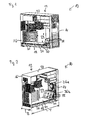
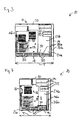
- FIGS. 1 to 3 show a first embodiment of a computer 10.
- the computer 10 is designed in particular as a so-called tower PC.
- the computer 10 has a computer housing 12, which is cuboidal.
- the computer housing 12 has a front wall 14, a rear wall 16, a bottom plate 18 and further housing walls 20, which together form the outer housing walls.
- the further housing walls 20 may be, for example, a cover plate and side walls.
- the housing walls 14, 16, 18, 20 may in particular consist of a metal sheet, preferably a steel sheet or have a steel sheet.
- an inner space 24 is formed.
- a motherboard 26 with a microprocessor and a plurality of plug-in cards 28 are arranged.
- drives 32 are also used.
- the drives 32 are in particular 3-1 / 2 "drives and 5-1 / 4" drives.
- an inner housing wall 34 is arranged, which extends in the embodiment of the computer housing 12 shown here over an entire width B and an entire depth T of the computer housing 12.
- the inner housing wall 34 separates a lower portion 24 a of the inner space 24 from an upper portion 24 b of the inner space 24.
- the upper portion 24 b of the inner space 24 is disposed above the lower portion 24 a of the inner space 24.
- the motherboard 26 with the microprocessor and the plug-in cards 28 are arranged in the upper portion 24b of the inner space 24 .
- the hard disk drives 30 are arranged in the lower portion 24 a of the inner space 24 . That is, the inner housing wall 34 divides the inner space 24 such that the lower portion 24a of the inner space 24 is formed as a channel extending the entire width B and the entire depth T of the computer case 12 in which the hard disk drives 30 are housed , Other components of the computer 10 are not arranged and received in the lower portion 24 a of the inner space 24.
- fans 36a, 36b are arranged in the front wall 14.
- a first fan 36a and a second fan 36b are arranged in the front wall 14.
- the two fans 36a, 36b are in particular arranged one above the other.
- the first fan 36a is associated with the upper portion 24b of the inner space 24 and may induce air flow in the upper portion 24b of the inner space 24 by which waste heat from the motherboard 26 may be dissipated to the microprocessor and the risers 28.
- the second fan 36 b is disposed below the first fan 36 a and associated with the lower portion 24 a of the inner space 24. With the lower, second fan 36b, in the lower portion 24a of the inner space 24, in which the hard disk drives 30 are arranged, an air flow can be generated by means of which waste heat can be dissipated from the hard disk drives 30 to the environment.
- the waste heat generated at the hard disk drives 30 can remain in a limited area of the inner space 24 and does not reach the upper portion 24 b of the inner space 24.
- a thermal load on the motherboard 26 with the microprocessor and the plug-in cards 28 can be avoided by the waste heat of the hard disk drives 30.
- the waste heat of the hard disk drives 30 can be sucked out of the lower portion 24 a of the inner space 24 by means of the lower, second fan 36 b.
- a burden of further arranged in the interior 24 of the computer case 12 components can be kept low.
- All hard disk drives 30 are arranged uniformly on the bottom plate 18. This means that the bottom plate 18 is substantially covered by the hard disk drives 30. This can be a very low center of gravity of the computer 10 can be achieved. Additional elements for preventing the tilting of the computer 10 can thus be avoided.
- the wall thicknesses of the outer housing walls 14, 16, 18, 20 can be small, so that a weight reduction of the computer housing 12 is possible.
- the outer housing walls 14, 16, 18, 20 instead of sheets with the usual sheet thickness of about 1.2 mm sheets with a sheet thickness of 0.6 to 0.8 mm for the outer housing walls 14, 16, 18, 20 to use.
- the inner housing wall 34 has openings 38, which allow an air-technical coupling of the lower portion 24 a of the inner space 24 with the upper portion 24 b of the inner space 24. It is thus possible that also the lower, second fan 36b, which causes a ventilation of the lower portion 24a of the inner space 24, can contribute to a ventilation of the upper portion 24b of the inner space 24. Thus, the lower, second fan 36b too a dissipation of the waste heat from the motherboard 26 with the microprocessor and the cards 28 contribute.
- FIG. 4 a further embodiment of the computer 10 is shown, with respect to the embodiment of the FIGS. 1 to 3 reduced depth T of the computer case 12.
- the hard disk drives 30 are arranged in this embodiment in their majority on the bottom plate 18 of the computer case 12. One of the hard disk drives 30 is located above another one of the hard disk drives 30 due to the small depth T of the computer case 12. Basically, however, in this embodiment, the plurality of hard disk drives 30 is disposed on the bottom plate 18. Thus, a low center of gravity of the computer 10 can be achieved, and additional elements for preventing tilting of the computer 10 can be avoided.
Landscapes
- Engineering & Computer Science (AREA)
- Theoretical Computer Science (AREA)
- Computer Hardware Design (AREA)
- Power Engineering (AREA)
- Human Computer Interaction (AREA)
- Physics & Mathematics (AREA)
- General Engineering & Computer Science (AREA)
- General Physics & Mathematics (AREA)
- Cooling Or The Like Of Electrical Apparatus (AREA)
- Casings For Electric Apparatus (AREA)
Abstract
Description
- Die Erfindung betrifft ein Computergehäuse und einen Computer.
- Computer, insbesondere so genannte Tower-PC, erreichen teilweise eine hohe Abwärmelast. Computer müssen deshalb effizient be- und entlüftet werden, um die Abwärme aus dem Computergehäuse abzuführen. Des Weiteren können in dem Computergehäuse angeordnete Laufwerke Vibrationen und Geräusche des Computers verursachen. Die entstehenden Geräusche sollten möglichst schwach sein.
- Der Erfindung liegt die Aufgabe zu Grunde, ein Computergehäuse und einen Computer zu schaffen, mit denen eine sichere und effiziente Be- und Entlüftung des Computers möglich ist.
- Die Aufgabe wird gelöst durch die Merkmale des unabhängigen Patentanspruchs. Vorteilhafte Ausgestaltungen der Erfindung sind in den Unteransprüchen gekennzeichnet.
- Gemäß eines ersten Aspekts zeichnet sich die Erfindung aus durch ein Computergehäuse, das aufweist äußere Gehäusewände, innerhalb denen ein Innenraum zur Aufnahme einer Hauptplatine, von Steckkarten und mindestens eines Festplattenlaufwerks ausgebildet ist, und eine in dem Innenraum angeordnete innere Gehäusewand. Die innere Gehäusewand ist ausgebildet zur räumlichen Trennung eines unteren Abschnitts des Innenraums von einem über dem unteren Abschnitt des Innenraums angeordneten oberen Abschnitt des Innenraums. Der obere Abschnitt des Innenraums ist zur Aufnahme der Hauptplatine und der Steckkarten und der untere Abschnitt des Innenraums ist zur Aufnahme der Festplattenlaufwerke ausgebildet.
- Dies hat den Vorteil, dass die Abwärme der Festplattenlaufwerke auf den separaten unteren Abschnitt des Innenraums beschränkt werden kann. Damit kann eine Belastung der Hauptplatine und Steckkarten mit der Abwärme der Festplattenlaufwerke vermieden werden. Die Festplattenlaufwerke können in einem tief gelegenen Bereich des Innenraums angeordnet sein. Damit ist ein niedriger Schwerpunkt des Computers möglich. Eigenschwingungen oder Vibrationen des Computergehäuses können sehr klein sein. Damit ist eine nur geringe Geräuschentwicklung möglich. Des Weiteren kann das Computergehäuse mit Gehäusewänden geringer Wandstärke ausgebildet sein. Damit sind geringe Kosten und ein geringes Gewicht des Computergehäuses erreichbar.
- In einer bevorzugten Ausführungsform hat das Computergehäuse einen ersten Lüfter, der ausgebildet ist zum Erzeugen einer Luftströmung in dem oberen Abschnitt des Innenraums, und einem zweiten Lüfter. Der zweite Lüfter ist in einer der äußeren Gehäusewände oder in dem unteren Abschnitt des Innenraums angeordnet und ausgebildet zum Erzeugen einer Luftströmung in dem unteren Abschnitt des Innenraums. Dies ermöglicht es, die Abwärme der Festplattenlaufwerke mittels des zweiten Lüfters unabhängig von dem ersten Lüfter separat aus dem unteren Abschnitt des Innenraums abzuführen, ohne weitere im Innenraum angeordnete Bauteile thermisch zu belasten.
- In einer weiteren bevorzugten Ausführungsform ist das Computergehäuse quaderförmig ausgebildet. Der untere Abschnitt des Innenraums erstreckt sich über eine gesamte Breite und/oder eine gesamte Tiefe des Computergehäuses. Dies hat den Vorteil, dass eine gute Verteilung der Festplattenlaufwerke über die Fläche des unteren Abschnitts des Innenraums möglich ist.
- In einer weiteren bevorzugten Ausführungsform sind in der inneren Gehäusewand Öffnungen angeordnet, die ausgebildet sind zur lufttechnischen Kopplung des unteren Abschnitts des Innenraums mit dem oberen Abschnitt des Innenraums. Dies hat den Vorteil, dass mittels des Lüfters eine Luftströmung von dem oberen zu dem unteren Abschnitt des Innenraums erreicht werden kann. Damit kann eine Abfuhr der Abwärme aus dem gesamtem Innenraum des Gehäuses (mit der Hauptplatine und den Steckkarten) mittels des Lüfters erreicht werden.
- Gemäß eines zweiten Aspekts zeichnet sich die Erfindung aus durch einen Computer mit einem Computergehäuse gemäß des ersten Aspekts. Die äußeren Gehäusewände weisen eine Bodenplatte auf, die den unteren Abschnitt des Innenraums nach unten begrenzt. Alle oder mindestens eine Mehrzahl der Festplattenlaufwerke sind auf der Bodenplatte angeordnet.
- Insbesondere bedecken die Festplattenlaufwerke die Bodenplatte im Wesentlichen vollständig.
- Dies hat den Vorteil, dass ein sehr niedriger Schwerpunkt des Computers möglich ist. Des Weiteren sind keine zusätzlichen Elemente zum Verhindern des Kippens des Computers erforderlich.
- Ausführungsbeispiele der Erfindung sind im Folgenden anhand der schematischen Zeichnungen näher erläutert.
- Es zeigen:
- Figur 1
- eine perspektivische Ansicht eines Computers in einer ersten Ausführungsform,
- Figur 2
- eine weitere perspektivische Ansicht des Computers,
- Figur 3
- eine Seitenansicht des Computers, und
- Figur 4
- eine perspektivische Ansicht des Computers in einer weiteren Ausführungsform.
- Elemente gleicher Konstruktion oder Funktion sind figurenübergreifend mit den gleichen Bezugszeichen versehen.
- Die
Figuren 1 bis 3 zeigen eine erste Ausführungsform eines Computers 10. Der Computer 10 ist insbesondere als so genannter Tower-PC ausgebildet. Der Computer 10 hat ein Computergehäuse 12, das quaderförmig ausgebildet ist. - Das Computergehäuse 12 weist eine Frontwand 14, eine Rückwand 16, eine Bodenplatte 18 und weitere Gehäusewände 20 auf, die zusammen die äußeren Gehäusewände bilden. Die weiteren Gehäusewände 20 können beispielsweise eine Deckplatte und Seitenwände sein.
- Die Gehäusewände 14, 16, 18, 20 können insbesondere aus einem Metallblech, vorzugsweise einem Stahlblech bestehen oder ein Stahlblech aufweisen.
- Innerhalb der äußeren Gehäusewände 14, 16, 18, 20 ist ein Innenraum 24 ausgebildet. In dem Innenraum 24 sind eine Hauptplatine 26 mit einem Mikroprozessor und mehrere Steckkarten 28 angeordnet.
- In dem Innenraum 24 sind weiter Festplattenlaufwerke 30 angeordnet.
- In Öffnungen der Frontwand 14 sind darüber hinaus weitere Laufwerke 32 eingesetzt. Die Laufwerke 32 sind insbesondere 3-1/2"-Laufwerke und 5-1/4"-Laufwerke.
- In dem Innenraum 24 ist eine innere Gehäusewand 34 angeordnet, die sich in der hier gezeigten Ausführungsform des Computergehäuses 12 über eine gesamte Breite B und eine gesamte Tiefe T des Computergehäuses 12 erstreckt. Die innere Gehäusewand 34 trennt einen unteren Abschnitt 24a des Innenraums 24 von einem oberen Abschnitt 24b des Innenraums 24. Der obere Abschnitt 24b des Innenraums 24 ist oberhalb des unteren Abschnitts 24a des Innenraums 24 angeordnet.
- In dem oberen Abschnitt 24b des Innenraums 24 sind die Hauptplatine 26 mit dem Mikroprozessor und die Steckkarten 28 angeordnet. In dem unteren Abschnitt 24a des Innenraums 24 sind die Festplattenlaufwerke 30 angeordnet. Dies bedeutet, dass die innere Gehäusewand 34 dem Innenraum 24 derart unterteilt, dass der untere Abschnitt 24a des Innenraums 24 als ein sich über die gesamte Breite B und die gesamte Tiefe T des Computergehäuses 12 erstreckender Kanal ausgebildet ist, in dem die Festplattenlaufwerke 30 aufgenommen sind. Weitere Komponenten des Computers 10 sind in dem unteren Abschnitt 24a des Innenraums 24 nicht angeordnet und aufgenommen.
- In der Frontwand 14 sind Lüfter 36a, 36b angeordnet. In der in den
Figuren 1 bis 3 gezeigten Ausführungsform des Computergehäuses 12 sind in der Frontwand 14 insbesondere ein erster Lüfter 36a und ein zweiter Lüfter 36b angeordnet. Die beiden Lüfter 36a, 36b sind insbesondere übereinander angeordnet. Der erste Lüfter 36a ist dem oberen Abschnitt 24b des Innenraums 24 zugeordnet und kann eine Luftströmung in dem oberen Abschnitt 24b des Innenraums 24 herbeiführen, mittels der Abwärme von der Hauptplatine 26 mit dem Mikroprozessor und den Steckkarten 28 abgeführt werden kann. - Der zweite Lüfter 36b ist unterhalb des ersten Lüfters 36a angeordnet und dem unteren Abschnitt 24a des Innenraums 24 zugeordnet. Mit dem unteren, zweiten Lüfter 36b kann in dem unteren Abschnitt 24a des Innenraums 24, in dem die Festplattenlaufwerke 30 angeordnet sind, ein Luftstrom erzeugt werden, mittels dem Abwärme von den Festplattenlaufwerken 30 an die Umgebung abgeführt werden kann.
- Durch die Ausbildung des unteren Abschnitts 24a des Innenraums 24 mittels der inneren Gehäusewand 34 kann erreicht werden, dass die an den Festplattenlaufwerken 30 anfallende Abwärme in einem begrenzten Bereich des Innenraums 24 verbleiben kann, und nicht in den oberen Abschnitt 24b des Innenraums 24 gelangt. Damit kann eine thermische Belastung der Hauptplatine 26 mit dem Mikroprozessor und der Steckkarten 28 durch die Abwärme der Festplattenlaufwerke 30 vermieden werden. Die Abwärme der Festplattenlaufwerke 30 kann mittels des unteren, zweiten Lüfters 36b aus dem unteren Abschnitt 24a des Innenraums 24 abgesaugt werden. Damit kann eine Belastung weiterer im Innenraum 24 des Computergehäuses 12 angeordneter Bauteile gering gehalten werden.
- Alle Festplattenlaufwerke 30 sind gleichmäßig auf der Bodenplatte 18 angeordnet. Dies bedeutet, dass die Bodenplatte 18 im Wesentlichen durch die Festplattenlaufwerke 30 bedeckt ist. Damit kann ein sehr niedriger Schwerpunkt des Computers 10 erreicht werden. Zusätzliche Elemente zum Verhindern des Kippens des Computers 10 können so vermieden werden.
- Durch die feste Anordnung der Festplattenlaufwerke 30 an der Bodenplatte 18 im unteren Abschnitt 24a des Innenraums 24 können Eigenschwingungen oder Vibrationen des Computergehäuses 12 klein gehalten werden. Darüber hinaus kann die Kraftübertragung von den Festplattenlaufwerken 30 auf das Computergehäuse 12 klein gehalten werden, so dass geringere Stabilitätsanforderungen an das Computergehäuse 12 gestellt werden können. Insbesondere kann somit erreicht werden, dass die Geräuschentwicklung des Computers 10, insbesondere des Computergehäuses 12, sehr klein werden kann. Des Weiteren ist es möglich, anstelle aufwendiger Füße zum Aufstellen es Computergehäuses 12 einfache Füße einzusetzen.
- Durch die geringe mechanische Belastung des Computergehäuses 12 können die Wandstärken der äußeren Gehäusewände 14, 16, 18, 20 klein ausfallen, so dass eine Gewichtsreduzierung des Computergehäuses 12 möglich ist. Insbesondere ist es möglich, für die äußeren Gehäusewände 14, 16, 18, 20 anstatt von Blechen mit der üblichen Blechdicke von zirka 1,2 mm Bleche mit einer Blechdicke von 0,6 bis 0,8 mm für die äußeren Gehäusewände 14, 16, 18, 20 zu verwenden.
- Die innere Gehäusewand 34 weist Öffnungen 38 auf, die eine lufttechnische Kopplung des unteren Abschnitts 24a des Innenraums 24 mit dem oberen Abschnitt 24b des Innenraums 24 ermöglichen. Es ist so möglich, dass auch der untere, zweite Lüfter 36b, der eine Be- und Entlüftung des unteren Abschnitts 24a des Innenraums 24 bewirkt, zu einer Be- oder Entlüftung des oberen Abschnitts 24b des Innenraums 24 beitragen kann. Damit kann auch der untere, zweite Lüfter 36b zu einer Abfuhr der Abwärme von der Hauptplatine 26 mit dem Mikroprozessor und den Steckkarten 28 beitragen.
- In
Figur 4 ist eine weitere Ausführungsform des Computers 10 gezeigt, mit einer gegenüber der Ausführungsform derFiguren 1 bis 3 reduzierten Tiefe T des Computergehäuses 12. - Die Festplattenlaufwerke 30 sind in dieser Ausführungsform in ihrer Mehrzahl auf der Bodenplatte 18 des Computergehäuses 12 angeordnet. Eines der Festplattenlaufwerke 30 wird aufgrund der geringen Tiefe T des Computergehäuses 12 oberhalb von einem anderen der Festplattenlaufwerke 30 angeordnet. Grundsätzlich ist jedoch auch in dieser Ausführungsform die Mehrzahl der Festplattenlaufwerke 30 auf der Bodenplatte 18 angeordnet. Es kann so ein niedriger Schwerpunkt des Computers 10 erreicht werden, und zusätzliche Elemente zum Verhindern eines Kippens des Computers 10 können vermieden werden.
- Die Erfindung ist nicht auf die angegebenen Ausführungsbeispiele beschränkt. Weiterhin ist es möglich, die Merkmale der verschiedenen Ausführungsbeispiele miteinander zu kombinieren, so dass auch derartige Anordnungen von der Erfindung umfasst sind.
-
- 10
- Computer
- 12
- Computergehäuse
- 14
- Frontwand
- 16
- Rückwand
- 18
- Bodenplatte
- 20
- weitere Gehäusewände
- 24
- Innenraum
- 24a,b
- unterer, oberer Abschnitt des Innenraums
- 26
- Hauptplatine
- 28
- Steckkarten
- 30
- Festplattenlaufwerk
- 32
- weitere Laufwerke
- 34
- innere Gehäusewand
- 36a,b
- erster, zweiter Lüfter
- 38
- Öffnungen in innerer Gehäusewand
- B
- Breite von 12
- T
- Tiefe von 12
Claims (5)
- Computergehäuse (12), das aufweist- äußere Gehäusewände (14,16,18,20), innerhalb denen ein Innenraum (24) zur Aufnahme einer Hauptplatine (26), von Steckkarten (28) und mindestens eines Festplattenlaufwerks (30) ausgebildet ist, und- eine in dem Innenraum (24) angeordnete innere Gehäusewand (34), die ausgebildet ist zur räumlichen Trennung eines unteren Abschnitts (24a) des Innenraums (24) von einem über dem unteren Abschnitt (24a) des Innenraums (24) angeordneten oberen (24b) Abschnitt des Innenraums (24),wobei der obere Abschnitt (24b) des Innenraums (24) zur Aufnahme der Hauptplatine (26) und der Steckkarten (28) und der untere Abschnitt (24a) des Innenraums (24) zur Aufnahme der Festplattenlaufwerke (30) ausgebildet ist.
- Computergehäuse (12) nach Anspruch 1, mit einem ersten Lüfter (36a), der ausgebildet ist zum Erzeugen einer Luftströmung in dem oberen Abschnitt (24b) des Innenraums (24), und einem zweiten Lüfter (36b), wobei der zweite Lüfter (36b) in einer der äußeren Gehäusewände (14,16,18,20) oder in dem unteren Abschnitt (24a) des Innenraums (24) angeordnet ist, und ausgebildet ist zum Erzeugen einer Luftströmung in dem unteren Abschnitt (24a) des Innenraums (24).
- Computergehäuse (12) nach Anspruch 1 oder 2, wobei das Computergehäuse (12) quaderförmig ausgebildet ist, und der untere Abschnitt (24a ) des Innenraums (24) sich über eine gesamte Breite (B) und/oder eine gesamte Tiefe (T) des Computergehäuses (12) erstreckt.
- Computergehäuse (12) nach einem der Ansprüche 2 bis 3, wobei in der innere Gehäusewand (34) Öffnungen (38) angeordnet sind, die ausgebildet sind zur lufttechnischen Kopplung des unteren Abschnitts (24a) des Innenraums (24) mit dem oberen Abschnitt (24b) des Innenraums (24).
- Computer (10) mit einem Computergehäuse (12) nach einem der vorhergehenden Ansprüche, wobei die äußeren Gehäusewände (14,16,18,20) eine Bodenplatte (18) aufweisen, die den unteren Abschnitt (24a) des Innenraums (24) nach unten begrenzt, und alle oder mindestens eine Mehrzahl der Festplattenlaufwerke (30) auf der Bodenplatte (18) angeordnet sind.
Applications Claiming Priority (1)
| Application Number | Priority Date | Filing Date | Title |
|---|---|---|---|
| DE102009047967A DE102009047967B9 (de) | 2009-10-01 | 2009-10-01 | Computergehäuse und Computer |
Publications (3)
| Publication Number | Publication Date |
|---|---|
| EP2309362A2 true EP2309362A2 (de) | 2011-04-13 |
| EP2309362A3 EP2309362A3 (de) | 2014-07-30 |
| EP2309362B1 EP2309362B1 (de) | 2016-08-31 |
Family
ID=43033025
Family Applications (1)
| Application Number | Title | Priority Date | Filing Date |
|---|---|---|---|
| EP10177130.1A Not-in-force EP2309362B1 (de) | 2009-10-01 | 2010-09-16 | Computergehäuse und Computer |
Country Status (4)
| Country | Link |
|---|---|
| US (1) | US8537538B2 (de) |
| EP (1) | EP2309362B1 (de) |
| JP (1) | JP2011076611A (de) |
| DE (1) | DE102009047967B9 (de) |
Families Citing this family (4)
| Publication number | Priority date | Publication date | Assignee | Title |
|---|---|---|---|---|
| US20140146462A1 (en) * | 2012-11-26 | 2014-05-29 | Giovanni Coglitore | High Density Storage Applicance |
| US20160098068A1 (en) * | 2014-10-07 | 2016-04-07 | Antec, Inc. | Computer case providing multiple independent airflows |
| CN105549699B (zh) * | 2014-10-30 | 2019-03-08 | 英业达科技有限公司 | 利用散热通道散热的连接扩充式计算机装置 |
| CN112879331B (zh) * | 2021-02-28 | 2023-06-30 | 山东兴元化工有限公司 | 一种废水处理用的通风散热装置 |
Family Cites Families (18)
| Publication number | Priority date | Publication date | Assignee | Title |
|---|---|---|---|---|
| IT1267375B1 (it) * | 1994-01-31 | 1997-02-05 | Olivetti & Co Spa | Elaboratore elettronico |
| US5694294A (en) * | 1995-01-27 | 1997-12-02 | Hitachi, Ltd. | Portable computer with fan moving air from a first space created between a keyboard and a first circuit board and a second space created between the first circuit board and a second circuit board |
| US5701231A (en) * | 1996-05-03 | 1997-12-23 | Citicorp Development Center, Inc. | Personal computer enclosure with peripheral device mounting system |
| DE19742373C2 (de) * | 1997-09-25 | 2002-08-14 | Fujitsu Siemens Computers Gmbh | Computergehäuse |
| US6005770A (en) * | 1997-11-12 | 1999-12-21 | Dell U.S.A., L.P. | Computer and a system and method for cooling the interior of the computer |
| JPH11265233A (ja) * | 1998-03-16 | 1999-09-28 | Hitachi Ltd | ディスクアレイサブシステム |
| US6519138B1 (en) * | 1998-11-05 | 2003-02-11 | Apple Computer, Inc. | Modular logic board chassis for a desktop computer |
| JP2001249736A (ja) * | 2000-03-07 | 2001-09-14 | Toshiba Corp | ハードディスクユニットおよびそれを内蔵したコンピュータ装置 |
| US6522547B1 (en) * | 2000-04-19 | 2003-02-18 | Hewlett-Packard Company | Computers with modular components |
| US6549397B1 (en) * | 2000-05-26 | 2003-04-15 | Hewlett-Packard Company | Tower computer with low center of gravity |
| US6597569B1 (en) * | 2000-06-29 | 2003-07-22 | Intel Corporation | Partitioned computer platform |
| JP2002032148A (ja) * | 2000-07-14 | 2002-01-31 | Hitachi Ltd | 縦置き可能な情報処理装置 |
| DE10224274B4 (de) * | 2002-05-31 | 2004-12-02 | Fujitsu Siemens Computers Gmbh | Komponentenanordnung für einen Tower-PC |
| JP3950810B2 (ja) * | 2003-03-28 | 2007-08-01 | 株式会社日立製作所 | サーバ |
| DE202004001502U1 (de) * | 2004-02-02 | 2004-06-03 | Richard Wöhr GmbH | Gehäuse mit intergriertem Kühlsystem |
| DE102005047773B4 (de) | 2005-10-05 | 2007-05-16 | Fujitsu Siemens Computers Gmbh | Computergehäuse mit einem Gehäusekäfig |
| TWM300415U (en) * | 2006-03-17 | 2006-11-01 | Enermax Technology Corp | Computer casing with division structure |
| JP2008090772A (ja) * | 2006-10-05 | 2008-04-17 | Hitachi Ltd | 情報処理装置 |
-
2009
- 2009-10-01 DE DE102009047967A patent/DE102009047967B9/de not_active Expired - Fee Related
-
2010
- 2010-09-16 EP EP10177130.1A patent/EP2309362B1/de not_active Not-in-force
- 2010-09-30 JP JP2010222048A patent/JP2011076611A/ja active Pending
- 2010-10-01 US US12/895,949 patent/US8537538B2/en not_active Expired - Fee Related
Non-Patent Citations (1)
| Title |
|---|
| None |
Also Published As
| Publication number | Publication date |
|---|---|
| DE102009047967A1 (de) | 2011-04-07 |
| DE102009047967B4 (de) | 2011-06-16 |
| US20110080706A1 (en) | 2011-04-07 |
| US8537538B2 (en) | 2013-09-17 |
| JP2011076611A (ja) | 2011-04-14 |
| EP2309362A3 (de) | 2014-07-30 |
| DE102009047967B9 (de) | 2012-02-23 |
| EP2309362B1 (de) | 2016-08-31 |
Similar Documents
| Publication | Publication Date | Title |
|---|---|---|
| DE60317389T2 (de) | Abkühlungssystem für eng zusammengestellte Speichervorrichtungen | |
| DE69631693T2 (de) | Gehäuse für einen personalcomputer mit befestigungssystem für peripheriegeräte | |
| EP0988586B1 (de) | Vorrichtung zur kühlung eines in einem gehäuse untergebrachten personal computers | |
| DE102004031368A1 (de) | Lufthutzenkühler mit aktiver Konvektion | |
| EP2309362B1 (de) | Computergehäuse und Computer | |
| DE102012103113B3 (de) | Rackservereinschub | |
| DE102009030088B4 (de) | Gehäuse | |
| EP1085795B1 (de) | Gehäuse mit elektrischen und/oder elektronischen Einheiten | |
| DE102005063024B4 (de) | Luftleithaube | |
| DE29819318U1 (de) | Kühlkörper für Computer | |
| DE102020107646B4 (de) | Computer und Verfahren zum Festlegen einer Erweiterungskarte in einem Computer | |
| DE102009047968A1 (de) | Minicomputer | |
| WO2014128062A2 (de) | Modulares gehäusesystem eines personal computers und personal computer | |
| DE202014101348U1 (de) | Elektronische Baugruppen, die Luftklappen zum Bereitstellen selektiver Kühlung für auf Hauptplatinen verbaute Bauelemente einsetzen | |
| DE69836463T2 (de) | Horizontale Befestigung für einen Prozessor | |
| DE29604674U1 (de) | Computergehäuse | |
| DE202004012238U1 (de) | Mehrfach verwendbares Gehäuse für eine Festplatte oder ein optisches Laufwerk | |
| DE10134012B4 (de) | Stromversorgungseinheit | |
| DE202008004117U1 (de) | Montage- und Demontageanordnung eines Kühlers | |
| DE202017107299U1 (de) | Netzteil | |
| DE102008005723A1 (de) | Netzteil-Lüfter | |
| DE202025100149U1 (de) | Brandschutzklappeneinbausatz | |
| DE202006005940U1 (de) | Lärmarmes Computergehäuse | |
| DE29920297U1 (de) | Netzteil | |
| DE112022007971T5 (de) | Anordnung und verfahren zum montieren eines bedienfelds |
Legal Events
| Date | Code | Title | Description |
|---|---|---|---|
| PUAI | Public reference made under article 153(3) epc to a published international application that has entered the european phase |
Free format text: ORIGINAL CODE: 0009012 |
|
| AK | Designated contracting states |
Kind code of ref document: A2 Designated state(s): AL AT BE BG CH CY CZ DE DK EE ES FI FR GB GR HR HU IE IS IT LI LT LU LV MC MK MT NL NO PL PT RO SE SI SK SM TR |
|
| AX | Request for extension of the european patent |
Extension state: BA ME RS |
|
| PUAL | Search report despatched |
Free format text: ORIGINAL CODE: 0009013 |
|
| AK | Designated contracting states |
Kind code of ref document: A3 Designated state(s): AL AT BE BG CH CY CZ DE DK EE ES FI FR GB GR HR HU IE IS IT LI LT LU LV MC MK MT NL NO PL PT RO SE SI SK SM TR |
|
| AX | Request for extension of the european patent |
Extension state: BA ME RS |
|
| RIC1 | Information provided on ipc code assigned before grant |
Ipc: G06F 1/18 20060101AFI20140624BHEP |
|
| 17P | Request for examination filed |
Effective date: 20140825 |
|
| RBV | Designated contracting states (corrected) |
Designated state(s): AL AT BE BG CH CY CZ DE DK EE ES FI FR GB GR HR HU IE IS IT LI LT LU LV MC MK MT NL NO PL PT RO SE SI SK SM TR |
|
| 17Q | First examination report despatched |
Effective date: 20150226 |
|
| GRAP | Despatch of communication of intention to grant a patent |
Free format text: ORIGINAL CODE: EPIDOSNIGR1 |
|
| INTG | Intention to grant announced |
Effective date: 20160429 |
|
| RIN1 | Information on inventor provided before grant (corrected) |
Inventor name: KANNLER, BERNHARD Inventor name: SCHMID, MICHAEL |
|
| GRAS | Grant fee paid |
Free format text: ORIGINAL CODE: EPIDOSNIGR3 |
|
| GRAA | (expected) grant |
Free format text: ORIGINAL CODE: 0009210 |
|
| AK | Designated contracting states |
Kind code of ref document: B1 Designated state(s): AL AT BE BG CH CY CZ DK EE ES FI FR GB GR HR HU IE IS IT LI LT LU LV MC MK MT NL NO PL PT RO SE SI SK SM TR |
|
| RBV | Designated contracting states (corrected) |
Designated state(s): AL AT BE BG CH CY CZ DK EE ES FI FR GB GR HR HU IE IS IT LI LT LU LV MC MK MT NL NO PL PT RO SE SI SK SM TR |
|
| REG | Reference to a national code |
Ref country code: CH Ref legal event code: EP Ref country code: DE Ref legal event code: R108 Ref country code: GB Ref legal event code: FG4D Free format text: NOT ENGLISH |
|
| REG | Reference to a national code |
Ref country code: IE Ref legal event code: FG4D Free format text: LANGUAGE OF EP DOCUMENT: GERMAN |
|
| REG | Reference to a national code |
Ref country code: AT Ref legal event code: REF Ref document number: 825508 Country of ref document: AT Kind code of ref document: T Effective date: 20161015 |
|
| REG | Reference to a national code |
Ref country code: FR Ref legal event code: PLFP Year of fee payment: 7 |
|
| REG | Reference to a national code |
Ref country code: LT Ref legal event code: MG4D |
|
| REG | Reference to a national code |
Ref country code: NL Ref legal event code: MP Effective date: 20160831 |
|
| PG25 | Lapsed in a contracting state [announced via postgrant information from national office to epo] |
Ref country code: LT Free format text: LAPSE BECAUSE OF FAILURE TO SUBMIT A TRANSLATION OF THE DESCRIPTION OR TO PAY THE FEE WITHIN THE PRESCRIBED TIME-LIMIT Effective date: 20160831 Ref country code: FI Free format text: LAPSE BECAUSE OF FAILURE TO SUBMIT A TRANSLATION OF THE DESCRIPTION OR TO PAY THE FEE WITHIN THE PRESCRIBED TIME-LIMIT Effective date: 20160831 Ref country code: NO Free format text: LAPSE BECAUSE OF FAILURE TO SUBMIT A TRANSLATION OF THE DESCRIPTION OR TO PAY THE FEE WITHIN THE PRESCRIBED TIME-LIMIT Effective date: 20161130 Ref country code: HR Free format text: LAPSE BECAUSE OF FAILURE TO SUBMIT A TRANSLATION OF THE DESCRIPTION OR TO PAY THE FEE WITHIN THE PRESCRIBED TIME-LIMIT Effective date: 20160831 |
|
| PG25 | Lapsed in a contracting state [announced via postgrant information from national office to epo] |
Ref country code: GR Free format text: LAPSE BECAUSE OF FAILURE TO SUBMIT A TRANSLATION OF THE DESCRIPTION OR TO PAY THE FEE WITHIN THE PRESCRIBED TIME-LIMIT Effective date: 20161201 Ref country code: BE Free format text: LAPSE BECAUSE OF NON-PAYMENT OF DUE FEES Effective date: 20160930 Ref country code: ES Free format text: LAPSE BECAUSE OF FAILURE TO SUBMIT A TRANSLATION OF THE DESCRIPTION OR TO PAY THE FEE WITHIN THE PRESCRIBED TIME-LIMIT Effective date: 20160831 Ref country code: LV Free format text: LAPSE BECAUSE OF FAILURE TO SUBMIT A TRANSLATION OF THE DESCRIPTION OR TO PAY THE FEE WITHIN THE PRESCRIBED TIME-LIMIT Effective date: 20160831 Ref country code: SE Free format text: LAPSE BECAUSE OF FAILURE TO SUBMIT A TRANSLATION OF THE DESCRIPTION OR TO PAY THE FEE WITHIN THE PRESCRIBED TIME-LIMIT Effective date: 20160831 Ref country code: NL Free format text: LAPSE BECAUSE OF FAILURE TO SUBMIT A TRANSLATION OF THE DESCRIPTION OR TO PAY THE FEE WITHIN THE PRESCRIBED TIME-LIMIT Effective date: 20160831 |
|
| PG25 | Lapsed in a contracting state [announced via postgrant information from national office to epo] |
Ref country code: RO Free format text: LAPSE BECAUSE OF FAILURE TO SUBMIT A TRANSLATION OF THE DESCRIPTION OR TO PAY THE FEE WITHIN THE PRESCRIBED TIME-LIMIT Effective date: 20160831 Ref country code: EE Free format text: LAPSE BECAUSE OF FAILURE TO SUBMIT A TRANSLATION OF THE DESCRIPTION OR TO PAY THE FEE WITHIN THE PRESCRIBED TIME-LIMIT Effective date: 20160831 |
|
| REG | Reference to a national code |
Ref country code: CH Ref legal event code: PL |
|
| PG25 | Lapsed in a contracting state [announced via postgrant information from national office to epo] |
Ref country code: SM Free format text: LAPSE BECAUSE OF FAILURE TO SUBMIT A TRANSLATION OF THE DESCRIPTION OR TO PAY THE FEE WITHIN THE PRESCRIBED TIME-LIMIT Effective date: 20160831 Ref country code: SK Free format text: LAPSE BECAUSE OF FAILURE TO SUBMIT A TRANSLATION OF THE DESCRIPTION OR TO PAY THE FEE WITHIN THE PRESCRIBED TIME-LIMIT Effective date: 20160831 Ref country code: PT Free format text: LAPSE BECAUSE OF FAILURE TO SUBMIT A TRANSLATION OF THE DESCRIPTION OR TO PAY THE FEE WITHIN THE PRESCRIBED TIME-LIMIT Effective date: 20170102 Ref country code: CZ Free format text: LAPSE BECAUSE OF FAILURE TO SUBMIT A TRANSLATION OF THE DESCRIPTION OR TO PAY THE FEE WITHIN THE PRESCRIBED TIME-LIMIT Effective date: 20160831 Ref country code: BG Free format text: LAPSE BECAUSE OF FAILURE TO SUBMIT A TRANSLATION OF THE DESCRIPTION OR TO PAY THE FEE WITHIN THE PRESCRIBED TIME-LIMIT Effective date: 20161130 Ref country code: DK Free format text: LAPSE BECAUSE OF FAILURE TO SUBMIT A TRANSLATION OF THE DESCRIPTION OR TO PAY THE FEE WITHIN THE PRESCRIBED TIME-LIMIT Effective date: 20160831 Ref country code: PL Free format text: LAPSE BECAUSE OF FAILURE TO SUBMIT A TRANSLATION OF THE DESCRIPTION OR TO PAY THE FEE WITHIN THE PRESCRIBED TIME-LIMIT Effective date: 20160831 |
|
| REG | Reference to a national code |
Ref country code: IE Ref legal event code: MM4A |
|
| PG25 | Lapsed in a contracting state [announced via postgrant information from national office to epo] |
Ref country code: IT Free format text: LAPSE BECAUSE OF FAILURE TO SUBMIT A TRANSLATION OF THE DESCRIPTION OR TO PAY THE FEE WITHIN THE PRESCRIBED TIME-LIMIT Effective date: 20160831 |
|
| PLBE | No opposition filed within time limit |
Free format text: ORIGINAL CODE: 0009261 |
|
| STAA | Information on the status of an ep patent application or granted ep patent |
Free format text: STATUS: NO OPPOSITION FILED WITHIN TIME LIMIT |
|
| PG25 | Lapsed in a contracting state [announced via postgrant information from national office to epo] |
Ref country code: CH Free format text: LAPSE BECAUSE OF NON-PAYMENT OF DUE FEES Effective date: 20160930 Ref country code: LI Free format text: LAPSE BECAUSE OF NON-PAYMENT OF DUE FEES Effective date: 20160930 Ref country code: IE Free format text: LAPSE BECAUSE OF NON-PAYMENT OF DUE FEES Effective date: 20160916 |
|
| 26N | No opposition filed |
Effective date: 20170601 |
|
| PG25 | Lapsed in a contracting state [announced via postgrant information from national office to epo] |
Ref country code: LU Free format text: LAPSE BECAUSE OF NON-PAYMENT OF DUE FEES Effective date: 20160916 Ref country code: SI Free format text: LAPSE BECAUSE OF FAILURE TO SUBMIT A TRANSLATION OF THE DESCRIPTION OR TO PAY THE FEE WITHIN THE PRESCRIBED TIME-LIMIT Effective date: 20160831 |
|
| REG | Reference to a national code |
Ref country code: FR Ref legal event code: PLFP Year of fee payment: 8 |
|
| REG | Reference to a national code |
Ref country code: AT Ref legal event code: MM01 Ref document number: 825508 Country of ref document: AT Kind code of ref document: T Effective date: 20160916 |
|
| REG | Reference to a national code |
Ref country code: BE Ref legal event code: MM Effective date: 20160930 |
|
| PG25 | Lapsed in a contracting state [announced via postgrant information from national office to epo] |
Ref country code: AT Free format text: LAPSE BECAUSE OF NON-PAYMENT OF DUE FEES Effective date: 20160916 |
|
| PG25 | Lapsed in a contracting state [announced via postgrant information from national office to epo] |
Ref country code: CY Free format text: LAPSE BECAUSE OF FAILURE TO SUBMIT A TRANSLATION OF THE DESCRIPTION OR TO PAY THE FEE WITHIN THE PRESCRIBED TIME-LIMIT Effective date: 20160831 Ref country code: HU Free format text: LAPSE BECAUSE OF FAILURE TO SUBMIT A TRANSLATION OF THE DESCRIPTION OR TO PAY THE FEE WITHIN THE PRESCRIBED TIME-LIMIT; INVALID AB INITIO Effective date: 20100916 |
|
| PG25 | Lapsed in a contracting state [announced via postgrant information from national office to epo] |
Ref country code: MC Free format text: LAPSE BECAUSE OF FAILURE TO SUBMIT A TRANSLATION OF THE DESCRIPTION OR TO PAY THE FEE WITHIN THE PRESCRIBED TIME-LIMIT Effective date: 20160831 Ref country code: MT Free format text: LAPSE BECAUSE OF FAILURE TO SUBMIT A TRANSLATION OF THE DESCRIPTION OR TO PAY THE FEE WITHIN THE PRESCRIBED TIME-LIMIT Effective date: 20160831 Ref country code: MK Free format text: LAPSE BECAUSE OF FAILURE TO SUBMIT A TRANSLATION OF THE DESCRIPTION OR TO PAY THE FEE WITHIN THE PRESCRIBED TIME-LIMIT Effective date: 20160831 Ref country code: IS Free format text: LAPSE BECAUSE OF FAILURE TO SUBMIT A TRANSLATION OF THE DESCRIPTION OR TO PAY THE FEE WITHIN THE PRESCRIBED TIME-LIMIT Effective date: 20160831 Ref country code: TR Free format text: LAPSE BECAUSE OF FAILURE TO SUBMIT A TRANSLATION OF THE DESCRIPTION OR TO PAY THE FEE WITHIN THE PRESCRIBED TIME-LIMIT Effective date: 20160831 |
|
| REG | Reference to a national code |
Ref country code: FR Ref legal event code: PLFP Year of fee payment: 9 |
|
| PG25 | Lapsed in a contracting state [announced via postgrant information from national office to epo] |
Ref country code: AL Free format text: LAPSE BECAUSE OF FAILURE TO SUBMIT A TRANSLATION OF THE DESCRIPTION OR TO PAY THE FEE WITHIN THE PRESCRIBED TIME-LIMIT Effective date: 20160831 |
|
| PGFP | Annual fee paid to national office [announced via postgrant information from national office to epo] |
Ref country code: GB Payment date: 20230921 Year of fee payment: 14 |
|
| PGFP | Annual fee paid to national office [announced via postgrant information from national office to epo] |
Ref country code: FR Payment date: 20230918 Year of fee payment: 14 |
|
| GBPC | Gb: european patent ceased through non-payment of renewal fee |
Effective date: 20240916 |
|
| PG25 | Lapsed in a contracting state [announced via postgrant information from national office to epo] |
Ref country code: GB Free format text: LAPSE BECAUSE OF NON-PAYMENT OF DUE FEES Effective date: 20240916 |
|
| PG25 | Lapsed in a contracting state [announced via postgrant information from national office to epo] |
Ref country code: FR Free format text: LAPSE BECAUSE OF NON-PAYMENT OF DUE FEES Effective date: 20240930 |