EP2306253A1 - Kollisionsprüfgerät, kollisionsprüfverfahren und werkzeugmaschine mit dem interferenzprüfgerät - Google Patents
Kollisionsprüfgerät, kollisionsprüfverfahren und werkzeugmaschine mit dem interferenzprüfgerät Download PDFInfo
- Publication number
- EP2306253A1 EP2306253A1 EP09794404A EP09794404A EP2306253A1 EP 2306253 A1 EP2306253 A1 EP 2306253A1 EP 09794404 A EP09794404 A EP 09794404A EP 09794404 A EP09794404 A EP 09794404A EP 2306253 A1 EP2306253 A1 EP 2306253A1
- Authority
- EP
- European Patent Office
- Prior art keywords
- moving
- interference check
- axis
- movable body
- tool rest
- Prior art date
- Legal status (The legal status is an assumption and is not a legal conclusion. Google has not performed a legal analysis and makes no representation as to the accuracy of the status listed.)
- Granted
Links
Images


Classifications
-
- G—PHYSICS
- G05—CONTROLLING; REGULATING
- G05B—CONTROL OR REGULATING SYSTEMS IN GENERAL; FUNCTIONAL ELEMENTS OF SUCH SYSTEMS; MONITORING OR TESTING ARRANGEMENTS FOR SUCH SYSTEMS OR ELEMENTS
- G05B19/00—Programme-control systems
- G05B19/02—Programme-control systems electric
- G05B19/18—Numerical control [NC], i.e. automatically operating machines, in particular machine tools, e.g. in a manufacturing environment, so as to execute positioning, movement or co-ordinated operations by means of programme data in numerical form
- G05B19/406—Numerical control [NC], i.e. automatically operating machines, in particular machine tools, e.g. in a manufacturing environment, so as to execute positioning, movement or co-ordinated operations by means of programme data in numerical form characterised by monitoring or safety
- G05B19/4061—Avoiding collision or forbidden zones
-
- B—PERFORMING OPERATIONS; TRANSPORTING
- B23—MACHINE TOOLS; METAL-WORKING NOT OTHERWISE PROVIDED FOR
- B23Q—DETAILS, COMPONENTS, OR ACCESSORIES FOR MACHINE TOOLS, e.g. ARRANGEMENTS FOR COPYING OR CONTROLLING; MACHINE TOOLS IN GENERAL CHARACTERISED BY THE CONSTRUCTION OF PARTICULAR DETAILS OR COMPONENTS; COMBINATIONS OR ASSOCIATIONS OF METAL-WORKING MACHINES, NOT DIRECTED TO A PARTICULAR RESULT
- B23Q39/00—Metal-working machines incorporating a plurality of sub-assemblies, each capable of performing a metal-working operation
- B23Q39/02—Metal-working machines incorporating a plurality of sub-assemblies, each capable of performing a metal-working operation the sub-assemblies being capable of being brought to act at a single operating station
- B23Q39/021—Metal-working machines incorporating a plurality of sub-assemblies, each capable of performing a metal-working operation the sub-assemblies being capable of being brought to act at a single operating station with a plurality of toolheads per workholder, whereby the toolhead is a main spindle, a multispindle, a revolver or the like
- B23Q39/025—Metal-working machines incorporating a plurality of sub-assemblies, each capable of performing a metal-working operation the sub-assemblies being capable of being brought to act at a single operating station with a plurality of toolheads per workholder, whereby the toolhead is a main spindle, a multispindle, a revolver or the like with different working directions of toolheads on same workholder
- B23Q39/027—Metal-working machines incorporating a plurality of sub-assemblies, each capable of performing a metal-working operation the sub-assemblies being capable of being brought to act at a single operating station with a plurality of toolheads per workholder, whereby the toolhead is a main spindle, a multispindle, a revolver or the like with different working directions of toolheads on same workholder consecutive working of toolheads
-
- G—PHYSICS
- G05—CONTROLLING; REGULATING
- G05B—CONTROL OR REGULATING SYSTEMS IN GENERAL; FUNCTIONAL ELEMENTS OF SUCH SYSTEMS; MONITORING OR TESTING ARRANGEMENTS FOR SUCH SYSTEMS OR ELEMENTS
- G05B2219/00—Program-control systems
- G05B2219/30—Nc systems
- G05B2219/35—Nc in input of data, input till input file format
- G05B2219/35306—Interference of all tools of turret, or part of tool base with chuck, workpiece
-
- G—PHYSICS
- G05—CONTROLLING; REGULATING
- G05B—CONTROL OR REGULATING SYSTEMS IN GENERAL; FUNCTIONAL ELEMENTS OF SUCH SYSTEMS; MONITORING OR TESTING ARRANGEMENTS FOR SUCH SYSTEMS OR ELEMENTS
- G05B2219/00—Program-control systems
- G05B2219/30—Nc systems
- G05B2219/35—Nc in input of data, input till input file format
- G05B2219/35316—Interference checking between tool, machine, part, chuck, machining range
-
- G—PHYSICS
- G05—CONTROLLING; REGULATING
- G05B—CONTROL OR REGULATING SYSTEMS IN GENERAL; FUNCTIONAL ELEMENTS OF SUCH SYSTEMS; MONITORING OR TESTING ARRANGEMENTS FOR SUCH SYSTEMS OR ELEMENTS
- G05B2219/00—Program-control systems
- G05B2219/30—Nc systems
- G05B2219/35—Nc in input of data, input till input file format
- G05B2219/35317—Display tool shape, to select tool for program, or for interference
-
- G—PHYSICS
- G05—CONTROLLING; REGULATING
- G05B—CONTROL OR REGULATING SYSTEMS IN GENERAL; FUNCTIONAL ELEMENTS OF SUCH SYSTEMS; MONITORING OR TESTING ARRANGEMENTS FOR SUCH SYSTEMS OR ELEMENTS
- G05B2219/00—Program-control systems
- G05B2219/30—Nc systems
- G05B2219/39—Robotics, robotics to robotics hand
- G05B2219/39082—Collision, real time collision avoidance
Definitions
- the present invention relates to an interference check device which checks the interference of a movable body, a method for checking interference and a machine tool having an interference check device.
- an automatic lathe has conventionally been known in which, on a movable front tool rest which is movable in the X1-axial direction which orthogonally crosses the axial line of a first main spindle, a tool rest (cutting-off tool rest) is provided which is movable in the X2-axial direction which is in parallel with a second main spindle and the above-mentioned X1-axial direction.
- the cutting-off tool rest of this automatic lathe moves in a direction which orthogonally crosses the axial line of the main spindle by two moving means, i.e. the X1 axis and the X2 axis.
- an interference check device which checks interference of tool rests and interference of a tool rest and a stationary structure or the like (see Patent Document 2, for example) is known.
- the interference check device of the present invention has a configuration in which it is disposed in an apparatus provided with one or a plurality of moving bodies which are capable of moving in a predetermined direction and moving means for moving said one or a plurality of moving bodies, and has a plurality of moving means for moving at least one of the moving bodies in the same axial line direction, and conducts interference check when said movable body is moved, which comprises:
- the absolute movement amount calculating part may be configured such that a plurality of moving axes are synthesized in the same axial line direction by said plurality of moving means, a virtual axis is provided in the same axial direction as the moving axis, and the absolute movement amount is obtained based on this virtual axis. Further, a judging part may be provided which judges whether a plurality of moving axes for moving the same movable body in the same axial direction are present among the inputted moving axes.
- the method for checking interference of the present invention is a method in which an interference check is conducted in a device which is disposed in an apparatus which is provided with one or a plurality of moving bodies which are capable of moving in a predetermined direction and moving means for moving said one or a plurality of moving bodies, and has a plurality of moving means for moving at least one of said moving bodies, and conducts interference check when said movable body is moved, which comprises the steps of:
- one virtual axis is provided in the same direction as that of said plurality of moving axes, and the absolute movement amount is obtained based on this virtual axis.
- the machine tool according to the present invention is characterized in that it is provided with the above-mentioned interference check device.
- FIG. 1 shows a schematic view of the machine tool on which the interference check device of the present invention is provided.
- the machine tool is provided with a first main spindle 1 and a first tool rest 2 provided in correspondence with the first main spindle 1, a second main spindle 3 and a second tool rest 4 provided in correspondence with the second main spindle 3, a third main spindle 6 and a third tool rest 7 provided in correspondence with the third main spindle 6, and a fourth tool rest 9 provided such that it selectively corresponds to each of the main spindles 1, 3 and 6.
- the first main spindle 1, the first tool rest 2, the second main spindle 3, the second tool rest 4, the third main spindle 6, the third tool rest 7 and the fourth tool rest 9 are provided on a bed of the machine tool, which is not shown.
- the first main spindle 1 is movable in the Z1-axial direction which is the same as that of the axial line direction.
- the first main spindle 1 is moved in the Z1-axial direction by means of a motor for the Z1 axis, a feed screw mechanism or the like which constitute the moving means for the first main spindle 1.
- the first tool rest 2 is provided on an XY table which orthogonally crosses the Z1 axis and can be moved in the X1-axial direction and the Y1-axial direction which orthogonally cross with each other.
- the first tool rest 2 can be moved in the X1-axial direction and the Y1-axial direction together with this XY table.
- the XY table moves in the X1-axial direction by a motor for the X1 axis, a feed screw mechanism or the like constituting the means for moving the first tool rest 2 in the X1-axial direction, and moves in the Y1-axial direction by a motor for the Y1 axis, a feed screw mechanism or the like constituting the means for moving the first tool rest in the Y1-axial direction.
- the third main spindle 6 is arranged such that it is adjacent to the first main spindle 1 so that the axial line of the third main spindle 6 is in parallel with and in the same direction of the axial line of the first main spindle 1. Further, it can be moved in the Z3-axial direction which is the same direction as that of the axial line direction.
- the third main spindle 6 moves in the Z3-axial direction on a bed by a motor for the Z3 axis, a feed screw mechanism or the like which constitute the means for moving in the Z3-axial direction.
- the third tool rest 7 is provided on the XY table which orthogonally crosses the Z3 axis and can be moved in the X3- and Y3-axial directions which orthogonally cross with each other.
- This XY table moves in the X3-axial direction by a motor for the X3 axis, a feed screw mechanism or the like which constitute the means for moving the third tool rest 7 in the X3-axial direction, and moves in the Y3-axial direction by a motor for the Y3 axis, a feed screw mechanism or the like which constitute the means for moving the third tool rest 7 in the Y3-axial direction.
- the X1-axial direction and the X3-axial direction are set in the same direction, and the Y1-axial direction and the Y3-axial direction are set in the same direction.
- a moving table 8 On the bed, a moving table 8 is provided which can be moved in the A2-axial direction which is the same direction as that of the axial line of the Y1 axis and that of the Y3 axis.
- This moving table 8 moves in the A2-axial direction on the bed by means of a motor for the A2 axis, a feed screw mechanism or the like which constitute a means for moving the moving table 8 in the A2-axial direction.
- the second main spindle 3 and the second tool rest 4 are provided on the moving table 8, and can be moved in the A2-axial direction integrally with the moving table 8.
- the second main spindle 3 is arranged such that the axial line thereof is in the same direction of and in parallel with the axial line of the first main spindle 1 and the axial line of the third main spindle 6, and such that it is opposed to the first main spindle 1 and the third main spindle 6. Further, the second main spindle 3 can be moved in the Z2-axial direction which is the same axial direction as that of the axial line direction.
- the second main spindle 3 moves in the Z2-axial direction on the moving table 8 by a motor for the Z2 axis, a feed screw mechanism or the like which constitutes the means for moving the second main spindle 3 in the Z2-axial direction.
- the second tool rest 4 is provided on the XY table which orthogonally crosses the Z2 axis and can be moved in the X2-axial direction and the Y2-axial direction which orthogonally cross with each other.
- This XY table is provided on the moving table 8, and moves in the X2-axial direction on the moving table 8 by a motor for the X2 axis, a feed screw mechanism or the like constituting the means for moving the second tool rest 4 in the X2-axial direction, and then moves in the Y2-axial direction on the moving table 8 by a motor for the Y2 axis, a feed screw mechanism or the like constituting the means for moving the second tool rest 4 in the Y2-axial direction.
- the axial line direction of the X2 axis, the axial line direction of the X1 axis and the axial line direction of the X3 axis are set in the same direction, and the axial direction of the Y2 axis, the axial direction of the Y1 axis, the axial direction of the Y3 axis and the axial direction of the A2 axis are set in the same direction.
- the fourth tool rest 9 is provided on an YZ table which is provided on a bed and can be moved in the Y4-axial direction and the Z4-axial direction which orthogonally cross each other.
- This YZ table moves in the Y4-axial direction by a motor for the Y4 axis, a feed screw mechanism or the like which constitutes the means for moving the fourth tool rest 9 in the Y4 direction, and moves in the Z4-axial direction through a motor for the Z4 axis, a feed screw mechanism or the like which constitute the means for moving the fourth tool rest 9 in the Z4 direction.
- the Y4-axial direction is set in the same direction as that of the Y1-axial direction, the Y2-axial direction, the Y3-axial direction and the A2-axial direction, and the Z4-axial direction is set in the same direction as that of the Z1-axial direction, and the Z2-axial direction and the Z3-axial direction.
- the signal "+" indicates the direction of the movement of each movable body.
- the direction in which a tool becomes more distant from a workpiece piece is indicated as "+” and, although not shown, the direction in which a tool becomes more close to a workpiece is indicated as "-”.
- the X1-axial direction, the X2-axial direction and the X3-axial direction are the same axial line directions
- the Y1-axial direction, the Y2-axial direction, the A2-axial direction, the Y3-axial direction and the Y4-axial direction are the same axial line directions
- the Z1-axial direction, the Z2-axial direction, the Z3-axial direction and the Z4-axial direction are the same axial directions.
- the moving directions on the X1 axis, the X2 axis and the X3 axis may often be referred to as the X direction
- the moving directions on the Y1 axis, the Y2 axis, the A2 axis, the Y3 axis and the Y4 axis may be referred to as the Y direction
- the moving directions on the Z1 axis, the Z2 axis, the Z3 axis and the Z4 axis may be referred to as the Z direction.
- a control device 11 which controls the driving of each of the above-mentioned motors.
- the control device 11 is composed of an NC device.
- NC device controls the NC program which has been read by the control device 11 (NC device)
- a workpiece held on the first main spindle 1 can be machined by means of a tool mounted on the first tool rest 2 by the combination of the movement in the Z direction of the first main spindle 1 and the movements in the X and Y directions of the first tool rest 2.
- a workpiece held on the second main spindle 3 can be machined by means of a tool mounted on the second tool rest 4 by the combination of the movement in the Z direction of the second main spindle 3 and the movement in the X and Y directions of the second tool rest 4.
- a workpiece held on the third main spindle 6 can be machined by means of a tool mounted on the third tool rest 7 by the combination of the movement in the Z direction of the third main spindle 6 and the movements in the X and Y directions of the third tool rest 7.
- the fourth tool rest 9 is allowed to move in the Y direction and the Z direction, thereby to cause it to position such that it corresponds to any of the first main spindle 1 to the third main spindle 6.
- a workpiece held on any of the first main spindle 1 to the third main spindle 6 can be machined by a tool mounted on the fourth tool rest 9 by the combination of the movement of the main spindle in the Z direction and the movement of the fourth tool rest 9 in the Y direction and the Y direction.
- the second tool rest 4 can be moved in the Y direction by means of two moving means, that is, the moving means in the Y2-axial direction and the moving means in the A2-axial direction. Therefore, machining of a workpiece held on the second main spindle 3 by means of a tool mounted on the second tool rest 4 can be conducted on the moving table 8 by causing the second main spindle 3 and the second tool rest 4 to integrally move in the Y direction by the moving table 8.
- the second main spindle 3 is moved from a position at which the axial line of the first main spindle 1 and the axial line of the second main spindle 3 coincide a position at which the axial line of the third main spindle 6 and the axial line of the second main spindle 3 coincide, whereby machining of a workpiece held on the second main spindle 3 can be conducted by a tool mounted on the second tool rest 4.
- the control device 11 is provided with an interference check part 12 which checks interference which occurs when the first main spindle 1 to the third main spindle 6 and the first tool rest 2 to the fourth tool rest 7, which constitute the moving bodies in this machine tool, move.
- an interference check part 12 which checks interference which occurs when the first main spindle 1 to the third main spindle 6 and the first tool rest 2 to the fourth tool rest 7, which constitute the moving bodies in this machine tool, move.
- Interference check by the interference check part 12 can be conducted by a known method. However, in the interference check part 12, it is required to input and set a movable body to be checked for interference and a moving axis corresponding at least to the movement in the X-, Y- and Z-directions of the movable body.
- the first tool rest 2 and the fourth tool rest 9 are inputted as moving bodies to be checked for interference.
- the X1 axis is inputted as the moving axis in the X direction and the Y1 axis is inputted as the moving axis in the Y direction
- the Y4 axis is inputted as the moving axis in the Y direction
- the Z4 axis is inputted as the moving axis in the Z direction.
- an absolute amount calculating part 13 which synthesizes each of the movement amounts in a plurality of moving axes which have been inputted for one moving direction of one movable body, and calculates an absolute movement amount of the movable body in the moving direction. As shown in FIG.
- the interference check part 12 may have a configuration that, if a judging part 14 is provided in the interference part 12 and this judging part 14 judges that a plurality of moving axes are present for one movable body from a plurality of moving axes which have been inputted, the absolute movement calculating amount part 13 synthesizes the movement amount for each of these movement axes. It is needless to say that the judging part 14 may be provided in the absolute movement calculating part 13, or may be provided separately from the interference check part 12 and the absolute amount calculating part 13. In this embodiment, the interference check part 12, the absolute movement calculating part 13, or the combination of the interference check part and the absolute movement calculating part with the judging part 14 constitute the interference check device.
- the interference check part 12 when the second tool rest 4 is inputted as the movable body to be checked for interference, as the moving axis in the Y direction of the second tool rest 4, the Y2 axis and the A2 axis can be inputted.
- the absolute amount calculating part 13 synthesizes the movement amount on the Y2 axis of the second tool rest 4 relative to the moving table 8 by the moving means in the Y2 direction of the second tool rest 4 and the movement amount on the A2 axis of the moving table 8 relative to the bed by the moving means in the A2 direction, thereby to form a virtual moving axis (Y-direction virtual axis) of the second tool rest 4 relative to the bed, and the absolute movement amount (that is, a position on coordinates of the second tool rest 4 in the Y-direction virtual axis is obtained.
- the absolute movement amount can be obtained in advance with a predetermined reference position of a machine tool, for example, the center of the end reference surface or the first main spindle 1, being as the reference.
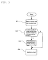
- a movable body to be checked for interference and the moving axis thereof are inputted in the interference check part 12.
- the moving axis of each of the second main spindle 3 the second tool rest 4 and the fourth tool rest 9 is inputted in the interference check part 12.
- the A2 axis is inputted as the Y-direction moving axis of the second main spindle 3
- the Y2 axis and the A2 axis are inputted as the Y-direction moving axis of the second tool rest 4.
- the moving axis of each of the first main spindle 1, the first tool rest 2 and the fourth tool rest 9 is inputted in the interference check part 12.
- the third main spindle 6, the third tool rest 7 and the fourth tool rest 9 may interfere with each other, the moving axis of the third main spindle 6, the third tool rest 7 and the fourth tool rest 9 is inputted in the interference check part 12.
- the judgment part 14 may be configured such that it can automatically conduct the above-mentioned judgment based on the above-mentioned input results.
- an operator may judge and input to the interference check part 12 so that the plurality of moving axes are inputted in the absolute movement amount calculating part 13 without providing the above-mentioned judging part 14.
- the absolute movement calculating part 13 provides one virtual axis from the plurality of moving axes.
- a virtual Y-direction moving axis i.e. the Y2' axis (Y-direction virtual axis)
- the two axes of the second tool rest 4 i.e., the A2 axis and the Y2 axis
- the step S4 starts.
- the subsequent step S4 starts without providing a virtual axis. Then, in the step S4, the interference check part 12 conducts interference check from the amount of movement in each moving axis and the above-mentioned absolute movement amount in the virtual axis.
- FIG. 4 shows one example of interference check of the second tool rest 4 in which the Y2' axis, which is the Y-direction virtual axis, is set and the fourth tool rest 9.
- An interference check region (the region 4a surrounded by a dotted line) including the second tool rest 4 and the tool T mounted thereon and an interference check region (the region 9a surrounded by a dotted line) including the fourth tool rest 9 and the tool T mounted thereon. From the current positions of the second tool rest 4 and the fourth tool rest 9, based on the movement instructions in the X2 direction, the Y2 direction and the A2 direction for the second tool rest 4, determination is made on the position to which the second tool rest 4 moves on the Y2' axis and the X2 axis.
- the interference check part 13 judges that interference occurs between the second tool rest 4 and the fourth tool rest 9, controls the movement of the second tool rest 4 and the fourth tool rest 9, and announces by means of an alarm or the like that interference occurs.
- interference check of the movable body can be easily conducted even when a plurality of moving means are provided in the same moving direction of one movable body.
- the interference check part 12 and the absolute movement calculating part 13 may be provided on the same control device 11, or may be provided separately from the control device 11.
- the interference check part 12 and the absolute amount calculating part 13 may be separate bodies or may be an integrated body. Further, it may be configured such that the absolute movement calculating part 13 starts if a plurality of moving axes which are in the same direction for one movable body are inputted in the interference check part 12.
- the configuration of the input part of the moving axis due to a configuration in which the moving direction to which the moving axis to be inputted corresponds can be arbitrarily set, a configuration in which a plurality of moving axes for one direction can be inputted in advance, a configuration in which one moving axis can be inputted relative to each of moving directions and, at the same time, a moving axis is inputted separately such that the moving direction thereof can be arbitrarily set, or the like, a plurality of moving axes can be inputted for one moving direction.
- the moving axis in the Y direction of the second tool rest 4 is not limited to a tool rest, and it may be a main spindle or other moving bodies.
- the present invention can be applied to a case where a plurality of moving axes are present not only in the Y direction but also in the X direction or the Z direction.
- the number of the moving axis to be synthesized is not limited to two, and the present invention can be applied to the synthesis of three or more moving axes.
- the absolute amount calculating part 13 may be respectively provided for each of the moving axes in the X-, Y- and Z-directions, or the common absolute amount calculating part 13 may be provided for each of the moving axes in the X-, Y- and Z-directions,
- the present invention can be applied not only to a case where there are a plurality of moving bodies and check of interference of moving bodies and check of interference of a movable body and a stationary part is conducted, but also to a case where there is only one movable body and check of interference of this movable body with a stationary part is conducted.
- the interference check device and the interference check method of the present invention can be applied not only to machine tools but also to all devices which require interference check.
Landscapes
- Engineering & Computer Science (AREA)
- Human Computer Interaction (AREA)
- Manufacturing & Machinery (AREA)
- Physics & Mathematics (AREA)
- General Physics & Mathematics (AREA)
- Automation & Control Theory (AREA)
- Mechanical Engineering (AREA)
- Numerical Control (AREA)
- Machine Tool Sensing Apparatuses (AREA)
Applications Claiming Priority (2)
| Application Number | Priority Date | Filing Date | Title |
|---|---|---|---|
| JP2008179912 | 2008-07-10 | ||
| PCT/JP2009/062302 WO2010004960A1 (ja) | 2008-07-10 | 2009-07-06 | 干渉チェック装置及び干渉チェック方法並びに干渉チェック装置を備えた工作機械 |
Publications (3)
| Publication Number | Publication Date |
|---|---|
| EP2306253A1 true EP2306253A1 (de) | 2011-04-06 |
| EP2306253A4 EP2306253A4 (de) | 2013-06-26 |
| EP2306253B1 EP2306253B1 (de) | 2016-05-04 |
Family
ID=41507073
Family Applications (1)
| Application Number | Title | Priority Date | Filing Date |
|---|---|---|---|
| EP09794404.5A Not-in-force EP2306253B1 (de) | 2008-07-10 | 2009-07-06 | Kollisionsprüfgerät, kollisionsprüfverfahren und werkzeugmaschine mit dem kollisionsprüfgerät |
Country Status (8)
| Country | Link |
|---|---|
| US (1) | US9110459B2 (de) |
| EP (1) | EP2306253B1 (de) |
| JP (1) | JP5554235B2 (de) |
| KR (1) | KR101575780B1 (de) |
| CN (1) | CN102089722B (de) |
| ES (1) | ES2579434T3 (de) |
| TW (1) | TWI477933B (de) |
| WO (1) | WO2010004960A1 (de) |
Cited By (3)
| Publication number | Priority date | Publication date | Assignee | Title |
|---|---|---|---|---|
| CN103707109A (zh) * | 2013-12-26 | 2014-04-09 | 北京航空航天大学 | 一种圆周阵列曲面结构五轴同步加工装置 |
| EP3626392A1 (de) * | 2018-09-19 | 2020-03-25 | ETA SA Manufacture Horlogère Suisse | Bearbeitungszentrum für uhrenkomponenten |
| CH718535B1 (de) * | 2022-03-23 | 2023-03-15 | Reishauer Ag | Verfahren und Werkzeugmaschinensystem zur Kollisionsprüfung eines Bearbeitungsprozesses, mit Ersatzwerkstück. |
Families Citing this family (9)
| Publication number | Priority date | Publication date | Assignee | Title |
|---|---|---|---|---|
| US5300034A (en) * | 1992-07-29 | 1994-04-05 | Minnesota Mining And Manufacturing Company | Iv injection site for the reception of a blunt cannula |
| EP2998066B1 (de) * | 2014-09-19 | 2017-06-14 | Mikron Agie Charmilles AG | Hochspannungsvorrichtung zur Vorbeugung von Kollisionen für Werkzeugmaschinen |
| JP6411964B2 (ja) * | 2015-07-27 | 2018-10-24 | ファナック株式会社 | 工作機械とロボットのリアルタイム干渉確認システム |
| JP6783238B2 (ja) * | 2015-09-24 | 2020-11-11 | シチズン時計株式会社 | 工作機械の制御装置及びこの制御装置を備えた工作機械 |
| JP6687582B2 (ja) * | 2017-11-30 | 2020-04-22 | ファナック株式会社 | 情報処理装置 |
| DE102018123363B4 (de) * | 2018-09-24 | 2021-01-07 | Bystronic Laser Ag | Verfahren zur Kollisionsvermeidung und Laserbearbeitungsmaschine |
| DE102018125620A1 (de) * | 2018-10-16 | 2020-04-16 | Schuler Pressen Gmbh | Verfahren und Vorrichtung zum Schneiden einer Blechplatine aus einem kontinuierlich geförderten Blechband |
| DE102020206223A1 (de) | 2020-05-18 | 2021-11-18 | Sms Group Gmbh | Querhaupt zur Verwendung als Ober- und/oder Unterholm in einer Presse |
| WO2022264338A1 (ja) * | 2021-06-16 | 2022-12-22 | ファナック株式会社 | 制御装置、干渉チェック装置、及び制御システム |
Citations (1)
| Publication number | Priority date | Publication date | Assignee | Title |
|---|---|---|---|---|
| US6651279B1 (en) * | 2002-11-26 | 2003-11-25 | Ge Medical Systems Global Technology Company, Llc | Method and apparatus for collision avoidance in a patient positioning platform |
Family Cites Families (12)
| Publication number | Priority date | Publication date | Assignee | Title |
|---|---|---|---|---|
| JPS58155150A (ja) * | 1982-03-11 | 1983-09-14 | Yamazaki Mazak Corp | 4軸数値制御旋盤 |
| JPS63156601A (ja) * | 1986-12-22 | 1988-06-29 | Matsuo Sangyo Kk | 自動工作機 |
| US5127140A (en) * | 1989-12-18 | 1992-07-07 | Hitachi Seiki Co., Ltd. | Numerically-controlled lathe, numerically-controlled device therefor and processing procedure thereby |
| JPH04291605A (ja) * | 1991-03-20 | 1992-10-15 | Matsushita Electric Ind Co Ltd | 干渉防止機能を持つ加工装置 |
| JPH0852638A (ja) * | 1994-08-15 | 1996-02-27 | Toshiba Mach Co Ltd | 干渉チェック方法および加工プログラムチェック方法および加工適否チェック方法 |
| JP3464307B2 (ja) | 1995-03-24 | 2003-11-10 | シチズン時計株式会社 | Nc旋盤における干渉チェック方法 |
| JP3563191B2 (ja) * | 1996-02-26 | 2004-09-08 | 三菱電機株式会社 | 数値制御装置 |
| JPH11170117A (ja) * | 1997-12-11 | 1999-06-29 | Sodick Co Ltd | 工作機械の移動軸の制御方法及び装置 |
| JP4666675B2 (ja) * | 2004-04-19 | 2011-04-06 | シチズンホールディングス株式会社 | 数値制御旋盤におけるワークの加工方法 |
| JP4376815B2 (ja) * | 2005-03-15 | 2009-12-02 | 株式会社ツガミ | 自動旋盤及び加工方法 |
| JP2008027045A (ja) * | 2006-07-19 | 2008-02-07 | Fanuc Ltd | 干渉チェック機能を備える数値制御装置 |
| JP2009142915A (ja) * | 2007-12-12 | 2009-07-02 | Murata Mach Ltd | 工作機械およびその切削加工方法 |
-
2009
- 2009-07-06 KR KR1020117000284A patent/KR101575780B1/ko not_active IP Right Cessation
- 2009-07-06 ES ES09794404.5T patent/ES2579434T3/es active Active
- 2009-07-06 CN CN200980126679.6A patent/CN102089722B/zh not_active Expired - Fee Related
- 2009-07-06 JP JP2010519769A patent/JP5554235B2/ja not_active Expired - Fee Related
- 2009-07-06 US US12/737,358 patent/US9110459B2/en not_active Expired - Fee Related
- 2009-07-06 WO PCT/JP2009/062302 patent/WO2010004960A1/ja active Application Filing
- 2009-07-06 EP EP09794404.5A patent/EP2306253B1/de not_active Not-in-force
- 2009-07-10 TW TW098123506A patent/TWI477933B/zh not_active IP Right Cessation
Patent Citations (1)
| Publication number | Priority date | Publication date | Assignee | Title |
|---|---|---|---|---|
| US6651279B1 (en) * | 2002-11-26 | 2003-11-25 | Ge Medical Systems Global Technology Company, Llc | Method and apparatus for collision avoidance in a patient positioning platform |
Non-Patent Citations (1)
| Title |
|---|
| See also references of WO2010004960A1 * |
Cited By (6)
| Publication number | Priority date | Publication date | Assignee | Title |
|---|---|---|---|---|
| CN103707109A (zh) * | 2013-12-26 | 2014-04-09 | 北京航空航天大学 | 一种圆周阵列曲面结构五轴同步加工装置 |
| CN103707109B (zh) * | 2013-12-26 | 2016-07-06 | 北京航空航天大学 | 一种圆周阵列曲面结构五轴同步加工装置 |
| EP3626392A1 (de) * | 2018-09-19 | 2020-03-25 | ETA SA Manufacture Horlogère Suisse | Bearbeitungszentrum für uhrenkomponenten |
| US11524381B2 (en) | 2018-09-19 | 2022-12-13 | Eta Sa Manufacture Horlogere Suisse | Machining centre for timepiece components |
| CH718535B1 (de) * | 2022-03-23 | 2023-03-15 | Reishauer Ag | Verfahren und Werkzeugmaschinensystem zur Kollisionsprüfung eines Bearbeitungsprozesses, mit Ersatzwerkstück. |
| WO2023180102A1 (de) * | 2022-03-23 | 2023-09-28 | Reishauer Ag | Verfahren zur kollisionsprüfung eines bearbeitungsprozesses, mit ersatzwerkstück |
Also Published As
| Publication number | Publication date |
|---|---|
| EP2306253B1 (de) | 2016-05-04 |
| KR101575780B1 (ko) | 2015-12-08 |
| CN102089722B (zh) | 2014-07-23 |
| TWI477933B (zh) | 2015-03-21 |
| ES2579434T3 (es) | 2016-08-11 |
| JPWO2010004960A1 (ja) | 2012-01-05 |
| EP2306253A4 (de) | 2013-06-26 |
| US20110106291A1 (en) | 2011-05-05 |
| TW201015256A (en) | 2010-04-16 |
| KR20110026468A (ko) | 2011-03-15 |
| WO2010004960A1 (ja) | 2010-01-14 |
| JP5554235B2 (ja) | 2014-07-23 |
| US9110459B2 (en) | 2015-08-18 |
| CN102089722A (zh) | 2011-06-08 |
Similar Documents
| Publication | Publication Date | Title |
|---|---|---|
| EP2306253B1 (de) | Kollisionsprüfgerät, kollisionsprüfverfahren und werkzeugmaschine mit dem kollisionsprüfgerät | |
| CN106346315B (zh) | 能够取得工件原点的机床控制系统以及工件原点设定方法 | |
| JP4727689B2 (ja) | ワーク計測装置、衝突防止装置および工作機械 | |
| EP1881381A2 (de) | Numerisches Kontrollgerät mit Interferenzprüfungsfunktion | |
| US20080103741A1 (en) | Machining simulation system | |
| US20090164038A1 (en) | Method for optimizing the machining process in a machine | |
| JP2006004128A (ja) | 干渉確認装置 | |
| EP2937752B1 (de) | Werkzeugmaschine und interpretierendes Programm | |
| JP2007018145A (ja) | 工作機械の干渉チェック装置 | |
| KR102632038B1 (ko) | 이상 검출장치 및 이상 검출장치를 구비한 공작기계 | |
| JP2015225617A (ja) | 数値制御装置と制御方法 | |
| CN114144280A (zh) | 在数控机床上使用的控制装置,以及包括控制装置的机床 | |
| JPH08263116A (ja) | Nc旋盤における干渉チェック方法 | |
| JP2008036804A (ja) | 工作機械の早送り制御方法 | |
| KR101108211B1 (ko) | 복합선반용 파트프로그래밍 장치 및 복합 공정간 동기화 프로그램 생성방법 | |
| JP2008269501A (ja) | 加工支援システム、それに適用する統合サーバおよび統合サーバプログラム | |
| US8352066B2 (en) | Machine tool, operating method for a machine tool and objects associated therewith | |
| JP6935606B1 (ja) | 情報処理装置および情報処理プログラム | |
| JP2007249671A (ja) | 工作機械の衝突防止方法 | |
| JP3217737B2 (ja) | 工作機械精度計測システム | |
| KR102264337B1 (ko) | 공작기계의 충돌 및 간섭 확인을 위한 hmi 장치 | |
| CN102478817A (zh) | 新型复合型数控机床 | |
| JP7175340B2 (ja) | 工作機械、情報処理装置および情報処理プログラム | |
| EP4372497A1 (de) | Werkzeugmaschine | |
| EP4324591A1 (de) | Werkzeugmaschine |
Legal Events
| Date | Code | Title | Description |
|---|---|---|---|
| PUAI | Public reference made under article 153(3) epc to a published international application that has entered the european phase |
Free format text: ORIGINAL CODE: 0009012 |
|
| 17P | Request for examination filed |
Effective date: 20110106 |
|
| AK | Designated contracting states |
Kind code of ref document: A1 Designated state(s): AT BE BG CH CY CZ DE DK EE ES FI FR GB GR HR HU IE IS IT LI LT LU LV MC MK MT NL NO PL PT RO SE SI SK SM TR |
|
| AX | Request for extension of the european patent |
Extension state: AL BA RS |
|
| DAX | Request for extension of the european patent (deleted) | ||
| RAP1 | Party data changed (applicant data changed or rights of an application transferred) |
Owner name: CITIZEN MACHINERY MIYANO CO., LTD. |
|
| A4 | Supplementary search report drawn up and despatched |
Effective date: 20130528 |
|
| RIC1 | Information provided on ipc code assigned before grant |
Ipc: G05B 19/19 20060101AFI20130522BHEP Ipc: B23Q 39/02 20060101ALI20130522BHEP Ipc: B23B 1/00 20060101ALI20130522BHEP Ipc: B23Q 15/00 20060101ALI20130522BHEP Ipc: G05B 19/4061 20060101ALI20130522BHEP |
|
| 17Q | First examination report despatched |
Effective date: 20150224 |
|
| RAP1 | Party data changed (applicant data changed or rights of an application transferred) |
Owner name: CITIZEN MACHINERY CO., LTD. |
|
| GRAP | Despatch of communication of intention to grant a patent |
Free format text: ORIGINAL CODE: EPIDOSNIGR1 |
|
| INTG | Intention to grant announced |
Effective date: 20151215 |
|
| RIN1 | Information on inventor provided before grant (corrected) |
Inventor name: MATSUMOTO, HITOSHI |
|
| GRAS | Grant fee paid |
Free format text: ORIGINAL CODE: EPIDOSNIGR3 |
|
| GRAA | (expected) grant |
Free format text: ORIGINAL CODE: 0009210 |
|
| AK | Designated contracting states |
Kind code of ref document: B1 Designated state(s): AT BE BG CH CY CZ DE DK EE ES FI FR GB GR HR HU IE IS IT LI LT LU LV MC MK MT NL NO PL PT RO SE SI SK SM TR |
|
| REG | Reference to a national code |
Ref country code: GB Ref legal event code: FG4D |
|
| REG | Reference to a national code |
Ref country code: CH Ref legal event code: EP |
|
| REG | Reference to a national code |
Ref country code: AT Ref legal event code: REF Ref document number: 797436 Country of ref document: AT Kind code of ref document: T Effective date: 20160515 |
|
| REG | Reference to a national code |
Ref country code: IE Ref legal event code: FG4D |
|
| REG | Reference to a national code |
Ref country code: CH Ref legal event code: NV Representative=s name: ISLER AND PEDRAZZINI AG, CH |
|
| REG | Reference to a national code |
Ref country code: DE Ref legal event code: R096 Ref document number: 602009038455 Country of ref document: DE |
|
| PGFP | Annual fee paid to national office [announced via postgrant information from national office to epo] |
Ref country code: ES Payment date: 20160628 Year of fee payment: 8 |
|
| REG | Reference to a national code |
Ref country code: ES Ref legal event code: FG2A Ref document number: 2579434 Country of ref document: ES Kind code of ref document: T3 Effective date: 20160811 |
|
| REG | Reference to a national code |
Ref country code: NL Ref legal event code: MP Effective date: 20160504 |
|
| REG | Reference to a national code |
Ref country code: LT Ref legal event code: MG4D |
|
| PG25 | Lapsed in a contracting state [announced via postgrant information from national office to epo] |
Ref country code: FI Free format text: LAPSE BECAUSE OF FAILURE TO SUBMIT A TRANSLATION OF THE DESCRIPTION OR TO PAY THE FEE WITHIN THE PRESCRIBED TIME-LIMIT Effective date: 20160504 Ref country code: NO Free format text: LAPSE BECAUSE OF FAILURE TO SUBMIT A TRANSLATION OF THE DESCRIPTION OR TO PAY THE FEE WITHIN THE PRESCRIBED TIME-LIMIT Effective date: 20160804 Ref country code: LT Free format text: LAPSE BECAUSE OF FAILURE TO SUBMIT A TRANSLATION OF THE DESCRIPTION OR TO PAY THE FEE WITHIN THE PRESCRIBED TIME-LIMIT Effective date: 20160504 Ref country code: NL Free format text: LAPSE BECAUSE OF FAILURE TO SUBMIT A TRANSLATION OF THE DESCRIPTION OR TO PAY THE FEE WITHIN THE PRESCRIBED TIME-LIMIT Effective date: 20160504 |
|
| PGFP | Annual fee paid to national office [announced via postgrant information from national office to epo] |
Ref country code: IT Payment date: 20160713 Year of fee payment: 8 Ref country code: CH Payment date: 20160712 Year of fee payment: 8 Ref country code: DE Payment date: 20160711 Year of fee payment: 8 |
|
| REG | Reference to a national code |
Ref country code: AT Ref legal event code: MK05 Ref document number: 797436 Country of ref document: AT Kind code of ref document: T Effective date: 20160504 |
|
| PG25 | Lapsed in a contracting state [announced via postgrant information from national office to epo] |
Ref country code: HR Free format text: LAPSE BECAUSE OF FAILURE TO SUBMIT A TRANSLATION OF THE DESCRIPTION OR TO PAY THE FEE WITHIN THE PRESCRIBED TIME-LIMIT Effective date: 20160504 Ref country code: LV Free format text: LAPSE BECAUSE OF FAILURE TO SUBMIT A TRANSLATION OF THE DESCRIPTION OR TO PAY THE FEE WITHIN THE PRESCRIBED TIME-LIMIT Effective date: 20160504 Ref country code: GR Free format text: LAPSE BECAUSE OF FAILURE TO SUBMIT A TRANSLATION OF THE DESCRIPTION OR TO PAY THE FEE WITHIN THE PRESCRIBED TIME-LIMIT Effective date: 20160805 Ref country code: PT Free format text: LAPSE BECAUSE OF FAILURE TO SUBMIT A TRANSLATION OF THE DESCRIPTION OR TO PAY THE FEE WITHIN THE PRESCRIBED TIME-LIMIT Effective date: 20160905 Ref country code: SE Free format text: LAPSE BECAUSE OF FAILURE TO SUBMIT A TRANSLATION OF THE DESCRIPTION OR TO PAY THE FEE WITHIN THE PRESCRIBED TIME-LIMIT Effective date: 20160504 |
|
| PG25 | Lapsed in a contracting state [announced via postgrant information from national office to epo] |
Ref country code: BE Free format text: LAPSE BECAUSE OF NON-PAYMENT OF DUE FEES Effective date: 20160731 |
|
| PG25 | Lapsed in a contracting state [announced via postgrant information from national office to epo] |
Ref country code: RO Free format text: LAPSE BECAUSE OF FAILURE TO SUBMIT A TRANSLATION OF THE DESCRIPTION OR TO PAY THE FEE WITHIN THE PRESCRIBED TIME-LIMIT Effective date: 20160504 Ref country code: DK Free format text: LAPSE BECAUSE OF FAILURE TO SUBMIT A TRANSLATION OF THE DESCRIPTION OR TO PAY THE FEE WITHIN THE PRESCRIBED TIME-LIMIT Effective date: 20160504 Ref country code: EE Free format text: LAPSE BECAUSE OF FAILURE TO SUBMIT A TRANSLATION OF THE DESCRIPTION OR TO PAY THE FEE WITHIN THE PRESCRIBED TIME-LIMIT Effective date: 20160504 Ref country code: SK Free format text: LAPSE BECAUSE OF FAILURE TO SUBMIT A TRANSLATION OF THE DESCRIPTION OR TO PAY THE FEE WITHIN THE PRESCRIBED TIME-LIMIT Effective date: 20160504 Ref country code: CZ Free format text: LAPSE BECAUSE OF FAILURE TO SUBMIT A TRANSLATION OF THE DESCRIPTION OR TO PAY THE FEE WITHIN THE PRESCRIBED TIME-LIMIT Effective date: 20160504 |
|
| REG | Reference to a national code |
Ref country code: DE Ref legal event code: R097 Ref document number: 602009038455 Country of ref document: DE |
|
| PG25 | Lapsed in a contracting state [announced via postgrant information from national office to epo] |
Ref country code: PL Free format text: LAPSE BECAUSE OF FAILURE TO SUBMIT A TRANSLATION OF THE DESCRIPTION OR TO PAY THE FEE WITHIN THE PRESCRIBED TIME-LIMIT Effective date: 20160504 Ref country code: SM Free format text: LAPSE BECAUSE OF FAILURE TO SUBMIT A TRANSLATION OF THE DESCRIPTION OR TO PAY THE FEE WITHIN THE PRESCRIBED TIME-LIMIT Effective date: 20160504 Ref country code: BE Free format text: LAPSE BECAUSE OF FAILURE TO SUBMIT A TRANSLATION OF THE DESCRIPTION OR TO PAY THE FEE WITHIN THE PRESCRIBED TIME-LIMIT Effective date: 20160504 Ref country code: AT Free format text: LAPSE BECAUSE OF FAILURE TO SUBMIT A TRANSLATION OF THE DESCRIPTION OR TO PAY THE FEE WITHIN THE PRESCRIBED TIME-LIMIT Effective date: 20160504 |
|
| PLBE | No opposition filed within time limit |
Free format text: ORIGINAL CODE: 0009261 |
|
| STAA | Information on the status of an ep patent application or granted ep patent |
Free format text: STATUS: NO OPPOSITION FILED WITHIN TIME LIMIT |
|
| PG25 | Lapsed in a contracting state [announced via postgrant information from national office to epo] |
Ref country code: MC Free format text: LAPSE BECAUSE OF FAILURE TO SUBMIT A TRANSLATION OF THE DESCRIPTION OR TO PAY THE FEE WITHIN THE PRESCRIBED TIME-LIMIT Effective date: 20160504 |
|
| 26N | No opposition filed |
Effective date: 20170207 |
|
| GBPC | Gb: european patent ceased through non-payment of renewal fee |
Effective date: 20160804 |
|
| PG25 | Lapsed in a contracting state [announced via postgrant information from national office to epo] |
Ref country code: FR Free format text: LAPSE BECAUSE OF NON-PAYMENT OF DUE FEES Effective date: 20160801 |
|
| REG | Reference to a national code |
Ref country code: FR Ref legal event code: ST Effective date: 20170331 |
|
| REG | Reference to a national code |
Ref country code: IE Ref legal event code: MM4A |
|
| PG25 | Lapsed in a contracting state [announced via postgrant information from national office to epo] |
Ref country code: SI Free format text: LAPSE BECAUSE OF FAILURE TO SUBMIT A TRANSLATION OF THE DESCRIPTION OR TO PAY THE FEE WITHIN THE PRESCRIBED TIME-LIMIT Effective date: 20160504 |
|
| PG25 | Lapsed in a contracting state [announced via postgrant information from national office to epo] |
Ref country code: GB Free format text: LAPSE BECAUSE OF NON-PAYMENT OF DUE FEES Effective date: 20160804 Ref country code: IE Free format text: LAPSE BECAUSE OF NON-PAYMENT OF DUE FEES Effective date: 20160706 |
|
| PG25 | Lapsed in a contracting state [announced via postgrant information from national office to epo] |
Ref country code: LU Free format text: LAPSE BECAUSE OF NON-PAYMENT OF DUE FEES Effective date: 20160706 |
|
| REG | Reference to a national code |
Ref country code: DE Ref legal event code: R119 Ref document number: 602009038455 Country of ref document: DE |
|
| REG | Reference to a national code |
Ref country code: CH Ref legal event code: PL |
|
| PG25 | Lapsed in a contracting state [announced via postgrant information from national office to epo] |
Ref country code: LI Free format text: LAPSE BECAUSE OF NON-PAYMENT OF DUE FEES Effective date: 20170731 Ref country code: DE Free format text: LAPSE BECAUSE OF NON-PAYMENT OF DUE FEES Effective date: 20180201 Ref country code: CH Free format text: LAPSE BECAUSE OF NON-PAYMENT OF DUE FEES Effective date: 20170731 |
|
| PG25 | Lapsed in a contracting state [announced via postgrant information from national office to epo] |
Ref country code: CY Free format text: LAPSE BECAUSE OF FAILURE TO SUBMIT A TRANSLATION OF THE DESCRIPTION OR TO PAY THE FEE WITHIN THE PRESCRIBED TIME-LIMIT Effective date: 20160504 Ref country code: HU Free format text: LAPSE BECAUSE OF FAILURE TO SUBMIT A TRANSLATION OF THE DESCRIPTION OR TO PAY THE FEE WITHIN THE PRESCRIBED TIME-LIMIT; INVALID AB INITIO Effective date: 20090706 |
|
| PG25 | Lapsed in a contracting state [announced via postgrant information from national office to epo] |
Ref country code: TR Free format text: LAPSE BECAUSE OF FAILURE TO SUBMIT A TRANSLATION OF THE DESCRIPTION OR TO PAY THE FEE WITHIN THE PRESCRIBED TIME-LIMIT Effective date: 20160504 Ref country code: IS Free format text: LAPSE BECAUSE OF FAILURE TO SUBMIT A TRANSLATION OF THE DESCRIPTION OR TO PAY THE FEE WITHIN THE PRESCRIBED TIME-LIMIT Effective date: 20160504 Ref country code: MT Free format text: LAPSE BECAUSE OF NON-PAYMENT OF DUE FEES Effective date: 20160731 Ref country code: MK Free format text: LAPSE BECAUSE OF FAILURE TO SUBMIT A TRANSLATION OF THE DESCRIPTION OR TO PAY THE FEE WITHIN THE PRESCRIBED TIME-LIMIT Effective date: 20160504 |
|
| PG25 | Lapsed in a contracting state [announced via postgrant information from national office to epo] |
Ref country code: BG Free format text: LAPSE BECAUSE OF FAILURE TO SUBMIT A TRANSLATION OF THE DESCRIPTION OR TO PAY THE FEE WITHIN THE PRESCRIBED TIME-LIMIT Effective date: 20160504 |
|
| PG25 | Lapsed in a contracting state [announced via postgrant information from national office to epo] |
Ref country code: IT Free format text: LAPSE BECAUSE OF NON-PAYMENT OF DUE FEES Effective date: 20170706 |
|
| REG | Reference to a national code |
Ref country code: ES Ref legal event code: FD2A Effective date: 20181106 |
|
| PG25 | Lapsed in a contracting state [announced via postgrant information from national office to epo] |
Ref country code: ES Free format text: LAPSE BECAUSE OF NON-PAYMENT OF DUE FEES Effective date: 20170707 |