EP2306031A1 - Kennzeichnungssystem für Gewindebauteile - Google Patents
Kennzeichnungssystem für Gewindebauteile Download PDFInfo
- Publication number
- EP2306031A1 EP2306031A1 EP10180716A EP10180716A EP2306031A1 EP 2306031 A1 EP2306031 A1 EP 2306031A1 EP 10180716 A EP10180716 A EP 10180716A EP 10180716 A EP10180716 A EP 10180716A EP 2306031 A1 EP2306031 A1 EP 2306031A1
- Authority
- EP
- European Patent Office
- Prior art keywords
- thread
- markings
- marking system
- threaded
- threaded component
- Prior art date
- Legal status (The legal status is an assumption and is not a legal conclusion. Google has not performed a legal analysis and makes no representation as to the accuracy of the status listed.)
- Granted
Links
- 238000007373 indentation Methods 0.000 claims description 3
- 238000004804 winding Methods 0.000 abstract 2
- 238000004519 manufacturing process Methods 0.000 description 5
- 238000005096 rolling process Methods 0.000 description 4
- 238000011161 development Methods 0.000 description 3
- 230000018109 developmental process Effects 0.000 description 3
- 238000010276 construction Methods 0.000 description 2
- 238000001514 detection method Methods 0.000 description 2
- 239000003086 colorant Substances 0.000 description 1
- 230000001419 dependent effect Effects 0.000 description 1
- 238000011156 evaluation Methods 0.000 description 1
- 238000007689 inspection Methods 0.000 description 1
- 239000000463 material Substances 0.000 description 1
- 238000000034 method Methods 0.000 description 1
- 238000000465 moulding Methods 0.000 description 1
- 239000003973 paint Substances 0.000 description 1
Images
Classifications
-
- F—MECHANICAL ENGINEERING; LIGHTING; HEATING; WEAPONS; BLASTING
- F16—ENGINEERING ELEMENTS AND UNITS; GENERAL MEASURES FOR PRODUCING AND MAINTAINING EFFECTIVE FUNCTIONING OF MACHINES OR INSTALLATIONS; THERMAL INSULATION IN GENERAL
- F16B—DEVICES FOR FASTENING OR SECURING CONSTRUCTIONAL ELEMENTS OR MACHINE PARTS TOGETHER, e.g. NAILS, BOLTS, CIRCLIPS, CLAMPS, CLIPS OR WEDGES; JOINTS OR JOINTING
- F16B25/00—Screws that cut thread in the body into which they are screwed, e.g. wood screws
- F16B25/0036—Screws that cut thread in the body into which they are screwed, e.g. wood screws characterised by geometric details of the screw
-
- F—MECHANICAL ENGINEERING; LIGHTING; HEATING; WEAPONS; BLASTING
- F16—ENGINEERING ELEMENTS AND UNITS; GENERAL MEASURES FOR PRODUCING AND MAINTAINING EFFECTIVE FUNCTIONING OF MACHINES OR INSTALLATIONS; THERMAL INSULATION IN GENERAL
- F16B—DEVICES FOR FASTENING OR SECURING CONSTRUCTIONAL ELEMENTS OR MACHINE PARTS TOGETHER, e.g. NAILS, BOLTS, CIRCLIPS, CLAMPS, CLIPS OR WEDGES; JOINTS OR JOINTING
- F16B2200/00—Constructional details of connections not covered for in other groups of this subclass
- F16B2200/95—Constructional details of connections not covered for in other groups of this subclass with markings, colours, indicators or the like
-
- F—MECHANICAL ENGINEERING; LIGHTING; HEATING; WEAPONS; BLASTING
- F16—ENGINEERING ELEMENTS AND UNITS; GENERAL MEASURES FOR PRODUCING AND MAINTAINING EFFECTIVE FUNCTIONING OF MACHINES OR INSTALLATIONS; THERMAL INSULATION IN GENERAL
- F16B—DEVICES FOR FASTENING OR SECURING CONSTRUCTIONAL ELEMENTS OR MACHINE PARTS TOGETHER, e.g. NAILS, BOLTS, CIRCLIPS, CLAMPS, CLIPS OR WEDGES; JOINTS OR JOINTING
- F16B33/00—Features common to bolt and nut
- F16B33/02—Shape of thread; Special thread-forms
Definitions
- the invention relates to a system for marking threaded components.
- screws in the end face of their screw head have markings indicating, for example, the origin of the screws from a particular manufacturing plant.
- markings indicating, for example, the origin of the screws from a particular manufacturing plant.
- a screw marking system within which the screws have embossed on the front side of their screw head a geometric pattern ( DE 20 2006 008 622 ). This geometric pattern is to facilitate the detection of the manufacturer of the screw in the assembled state of the screw.
- the end face of the screw head lends itself to the attachment of such markers of course, since it is flat and sufficiently large so that markers can be easily attached.
- the front side of the screw head has the advantage that it is visible even when mounted.
- screws have a screw head, which has a relation to the shaft diameter of the screw only slightly larger diameter, so that outside the screw drive recess remains no more space for markings.
- screws especially longer screws, may also be loose in containers, for example on the construction site.
- the inspection of the front side of the screw head can be difficult, namely, when the screws must first be removed from the containers.
- threaded rods for the construction sector heads are missing in total. For cut threaded rods, the mark is completely missing, as it is only outside of the end pieces, where it is imprinted.
- the invention is based on the object to provide a way of attaching components with a thread (internal or external thread) information about the properties of the component so that this information also later, possibly even after removal of such a component, can be read again.
- a thread internal or external thread
- the invention proposes an identification system for threaded components with the features of claim 1. Further developments of the invention are the subject of dependent claims.
- markers which are arranged in a predetermined pattern, can be recognized when the screw or the threaded member is in a box or toolbox. Such markings can be recognized not only by eye, but also by machine. Especially with very long threaded components, there is sufficient space available to install such markings. Even if such a threaded component to be replaced, can one recognizes after removal of the same based on the markings of the removed threaded component, the markers and thus the coded information, for example, to what kind and / or quality it is in the threaded member. Because of the large available space can also be further information about the quality and the origin of the threaded component or other information, such as date of manufacture, manufacturing batch, place of manufacture ... encode.
- the markings are arranged in a narrow region extending parallel to the longitudinal axis of the threaded component. In this case, in a given position of the screw, all the markings can be seen by turning the area in question towards the observer.
- the markings are also possible to arrange the markings in a region extending over a circumference of the threaded component. It makes sense if the area extending over the circumference extends obliquely to the longitudinal axis, that is, for example along a helical line with the same pitch as the thread.
- markings can be configured is to form notches in the thread's thread edge. These notches are very easy to recognize. Since the course of the thread edge is fixed, this type of markings is particularly suitable for machine detection.
- markings can be designed is to mount small-sized depressions that both can be recognized by eye as well as by machine.
- the deformations serving as markings in rolling the threaded component are also rolled. This can be done both at the notches in the thread edge as well as in the small-sized depressions as well as other impressions.
- Small-sized depressions in the form of small dents can also be attached with the aid of lasers. It is also conceivable to print markings using colors.
- Assigning the markings for example, as notches in a thread edge along a narrow range, so each thread can have a value because of the constant pitch of the thread of the threaded component and the presence of a notch mean an evaluation of this position.
- Markings may thus generally be notches, recesses, barcodes, a lettering, colored areas, circumferential rings or also symbols applied at specific locations, for example squares and triangles or the like. Depending on the type of markings these are impressed when rolling the thread of the threaded component with or created by means of a laser or paint nozzles.
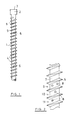
- FIG. 1 shows in a side view part of a screw, which serves as an example of externally threaded threaded components.
- the screw has a screw shaft 1, which at one end, in FIG. 1 above, with a screw head 2 is provided. From the end face 3 of the screw head 2, a drive recess goes into the interior of the screw head 2. There is only little space between the edge of the drive recess and the outer circumference of the screw head 2, so that there is only little space available for attaching markings or the like at this point.
- a thread 4 extends along a helix.
- the thread 4 has a sharp thread edge 5.
- notches 6 are formed in the thread edge 5 at some points of the thread. This molding is done when making the screw by rolling. How to get the FIG. 1 Some turns have no notches while other turns have notches 6.
- the illustrated screw can assign the thread turns starting from the screw head 2 from positions. Furthermore, one can say that, for example the presence of a notch 6 represents the number 1 and the absence of a notch 6 represents the number 0. Then the illustrated sequence of notches 6 would represent the digit sequence 0110110110111001. This number sequence can be assigned a meaning. It can be both the name of the manufacturer and the name of a quality of the material used of the screw.
- FIG. 2 In the cutout of a threaded component in FIG. 2 another way of marking is chosen.
- the impressions 8 are shown in the simplest case as circles. If one again starts from a straight line running parallel to the flanks of the shaft 1, three points are provided for the impressions in each intermediate space between two turns of the thread 4, at which such an impression 8 can be present.
- the first space 9 which is provided here with indentations 8, an impression 8 on the left and an impression 8 in the right place exists, in the following gap 10 is an impression 8 at the middle point, and in the next space 11 a Imprint on the left side available. It is also possible in this way to provide markings which can be used to encode certain meanings.
- impressions 8 can also be done with other types of deformations that can be formed by rolling in the manufacture of the screw. For example, one could make impressions in the flanks of the threads. Of course, the impressions 8 can take other forms.
- a letter can be impressed, the sequence of these letters yielding a word, if the screw is held at an angle.
Landscapes
- Engineering & Computer Science (AREA)
- General Engineering & Computer Science (AREA)
- Physics & Mathematics (AREA)
- Geometry (AREA)
- Mechanical Engineering (AREA)
- Length-Measuring Instruments Using Mechanical Means (AREA)
- Details Of Spanners, Wrenches, And Screw Drivers And Accessories (AREA)
Abstract
Description
- Die Erfindung betrifft ein System zur Kennzeichnung von Gewindebauteilen.
- Es ist bekannt, dass Schrauben in der Stirnfläche ihres Schraubenkopfs Markierungen aufweisen, die beispielsweise die Herkunft der Schrauben aus einem bestimmten Herstellungsbetrieb angeben. Außerdem können dort Angaben über beispielsweise Größen und Güte angegeben sein.
- Darüber hinaus ist ein Schraubenmarkierungssystem bekannt, innerhalb dessen die Schrauben auf der Stirnseite ihres Schraubenkopfs ein geometrisches Muster eingeprägt haben (
DE 20 2006 008 622 ). Dieses geometrische Muster soll in montiertem Zustand der Schraube das Erkennen des Herstellers der Schraube erleichtern. - Die Stirnseite des Schraubenkopfs bietet sich für die Anbringung solcher Markierungen natürlich an, da sie eben und ausreichend groß ist, so dass sich Markierungen leicht anbringen lassen. Darüber hinaus hat die Stirnseite des Schraubenkopfs den Vorteil, dass sie auch in montiertem Zustand sichtbar ist.
- Nun gibt es aber auch Fälle, wo Schrauben einen Schraubenkopf aufweisen, der einen gegenüber dem Schaftdurchmesser der Schraube nur unwesentlich vergrößerten Durchmesser aufweist, so dass außerhalb der Schraubenantriebsvertiefung kein Platz mehr für Markierungen bleibt. Außerdem können Schrauben, insbesondere längere Schrauben, auch lose in Behältern liegen, beispielsweise auf der Baustelle. Hier kann die Überprüfung der Stirnseite des Schraubenkopfs schwierig werden, wenn nämlich die Schrauben erst aus den Behältern entnommen werden müssen. Bei Gewindestangen für den Baubereich fehlen Köpfe insgesamt. Bei zugeschnittenen Gewindestangen fehlt die Markierung ganz, da sie nur außen an den Endstücken vorhanden ist, wo sie eingeprägt ist.
- Der Erfindung liegt die Aufgabe zu Grunde, eine Möglichkeit zu schaffen, wie man an Bauteilen mit einem Gewinde (Innen- oder Außengewinde) Informationen über Eigenschaften des Bauteils so anbringen kann, dass diese Informationen auch später, gegebenenfalls auch nach einer Entnahme eines solchen Bauteils, wieder gelesen werden können.
- Zur Lösung dieser Aufgabe schlägt die Erfindung ein Kennzeichnungssystem für Gewindebauteile mit den Merkmalen des Patentanspruchs 1 vor. Weiterbildungen der Erfindung sind Gegenstand von Unteransprüchen.
- Diese Markierungen, die in einem vorbestimmten Muster angeordnet sind, können erkannt werden, wenn die Schraube oder das Gewindebauteil in einer Schachtel oder einem Werkzeugkasten liegt. Derartige Markierungen können nicht nur mit dem Auge erkannt werden, sondern auch maschinell. Insbesondere bei sehr langen Gewindebauteilen steht ausreichend Platz zur Verfügung, um solche Markierungen anzubringen. Auch dann, wenn ein solches Gewindebauteil ersetzt werden soll, kann man nach Ausbau desselben anhand der Markierungen des ausgebauten Gewindebauteils die Markierungen und somit die codierte Information erkennen, beispielsweise um welche Art und/oder Qualität es sich bei dem Gewindebauteil handelt. Wegen des großen zur Verfügung stehenden Platzes lassen sich auch weitere Angaben über die Qualität und die Herkunft des Gewindebauteils oder andere Angaben, beispielsweise Herstellungsdatum, Herstellungscharge, Herstellungsort ... codieren.
- Insbesondere kann in Weiterbildung der Erfindung vorgesehen sein, dass die Markierungen in einem schmalen parallel zur Längsachse des Gewindebauteils verlaufenden Bereich angeordnet sind. In diesem Fall kann man in einer bestimmten Position der Schraube alle Markierungen erkennen, wenn man den Bereich, um den es sich handelt, in Richtung auf den Betrachter dreht.
- Es ist ebenfalls möglich, die Markierungen in einem sich über einen Umfang des Gewindebauteils erstreckenden Bereich anzuordnen. Dabei ist es sinnvoll, wenn der sich über den Umfang erstreckende Bereich schräg zur Längsachse verläuft, also beispielsweise längs einer Schraubenlinie mit der gleichen Steigung wie das Gewinde.
- Selbstverständlich ist auch eine Kombination beider Möglichkeiten vorgesehen.
- Eine Möglichkeit, wie die Markierungen ausgestaltet sein können, besteht darin, Kerben in der Gewindekante des Gewindes auszubilden. Diese Kerben lassen sich sehr leicht erkennen. Da der Verlauf der Gewindekante festliegt, eignet sich diese Art der Markierungen besonders auch für eine maschinelle Erkennung.
- Eine weitere Möglichkeit, wie die Markierungen ausgestaltet sein können, besteht darin, kleinformatige Vertiefungen anzubringen, die sowohl mit dem Auge als auch maschinell erkennbar sind.
- Um den Vorgang der Herstellung der Gewindebauteile mit Verformungen einfach zu gestalten, kann in Weiterbildung der Erfindung vorgesehen sein, dass die als Markierungen dienenden Verformungen beim Walzen des Gewindebauteils mit gewalzt werden. Dies kann sowohl bei den Kerben in der Gewindekante als auch bei den kleinformatigen Vertiefungen wie auch bei sonstigen Einprägungen geschehen.
- Kleinformatige Vertiefungen in Form von kleinen Dellen lassen sich auch mit Hilfe von Lasern anbringen. Denkbar ist auch das Aufdrucken von Markierungen mithilfe von Farben.
- Ordnet man die Markierungen beispielsweise als Kerben in einer Gewindekante längs eines schmalen Bereichs an, so kann jede Gewindewindung wegen der konstanten Steigung des Gewindes des Gewindebauteils einen Stellenwert haben und das Vorhandensein einer Kerbe eine Wertung dieses Stellenwerts bedeuten.
- Bei einer Anordnung von Markierungen längs des Umfangs kann man ebenfalls ein Rastermaß vorsehen und jedem Element des Rastermaßes einen Stellenwert zuordnen.
- Markierungen können somit allgemein Kerben, Vertiefungen, Barcodes, ein Schriftzug, farbige Flächen, umlaufende Ringe oder auch an bestimmten Stellen angebrachte Symbole, beispielsweise Quadrate und Dreiecke oder dergleichen sein. Je nach Art der Markierungen sind diese beim Walzen des Gewindes des Gewindebauteils mit eingeprägt oder mithilfe eines Lasers oder mittels Farbdüsen erstellt.
- Weitere Merkmale, Einzelheiten und Vorzüge der Erfindung ergeben sich aus den Ansprüchen und der Zusammenfassung, deren beider Wortlaut durch Bezugnahme zum Inhalt der Beschreibung gemacht wird, der folgenden Beschreibung bevorzugter Ausführungsformen der Erfi n-dung sowie anhand der Zeichnung. Hierbei zeigen:
- Figur 1
- eine abgebrochene Seitenansicht eines Gewindebauteils in Form einer Schraube;
- Figur 2
- in vergrößertem Maßstab einen Ausschnitt aus einem Ge- windeschaft.
- Die
Figur 1 zeigt in einer Seitenansicht einen Teil einer Schraube, die hier als Beispiel für mit einem Außengewinde versehene Gewindebauteile dient. Die Schraube hat einen Schraubenschaft 1, der an einem Ende, inFigur 1 oben, mit einem Schraubenkopf 2 versehen ist. Von der Stirnfläche 3 des Schraubenkopfs 2 aus geht eine Antriebsvertiefung in das Innere des Schraubenkopfs 2 hinein. Zwischen dem Rand der Antriebsvertiefung und dem Außenumfang des Schraubenkopfs 2 ist nur wenig Platz vorhanden, so dass an dieser Stelle nur wenig Platz zur Anbringung von Markierungen oder dergleichen zur Verfügung steht. - Über den Schaft 1 erstreckt sich ein Gewinde 4 längs einer Schraubenlinie. Das Gewinde 4 weist eine scharfe Gewindekante 5 auf. Längs einer gedachten Linie, die in
Figur 1 in der Mitte von oben nach unten verläuft, sind an einigen Stellen des Gewindes Kerben 6 in die Gewindekante 5 eingeformt. Dieses Einformen geschieht beim Herstellen der Schraube durch Walzen. Wie man derFigur 1 entnehmen kann, haben einige Windungen keine Kerben, während andere Windungen Kerben 6 aufweisen. - Geht man bei der dargestellten Schraube von dem Schraubenkopf 2 aus, so kann man den Gewindewindungen ausgehend vom Schraubenkopf 2 aus Stellenwerte zuordnen. Weiterhin kann man sagen, dass beispielsweise das Vorhandensein einer Kerbe 6 die Ziffer 1 und das Fehlen einer Kerbe 6 die Ziffer 0 darstellt. Dann würde die dargestellte Reihenfolge von Kerben 6 die Ziffernfolge 0110110110111001 darstellen. Dieser Ziffernfolge kann man eine Bedeutung zuordnen. Es kann sich dabei sowohl um die Bezeichnung des Herstellers als auch um die Bezeichnung einer Qualität des verwendeten Materials der Schraube handeln.
- Man kann auch weitergehend annehmen, dass in dem schmalen auf einen Blick sichtbaren Bereich an jeder Windung des Gewindes Platz für zwei Kerben 6 nebeneinander ist. Dann könnte an jeder Stelle eine Ziffer mit den Werten 0 bis 3 markiert werden.
- Bei dem Ausschnitt eines Gewindebauteils in
Figur 2 ist eine andere Art der Markierung gewählt. Hier sind in dem Bereich 7 des Schafts 1 zwischen jeweils zwei Windungen des Gewindes 4 Stellen zur Anbringung von Einprägungen 8 vorgesehen. Die Einprägungen 8 sind im einfachsten Fall als Kreise dargestellt. Geht man wieder von einer parallel zu den Flanken des Schafts 1 verlaufenden Gerade aus, so sind für die Einprägungen in jedem Zwischenraum zwischen zwei Windungen des Gewindes 4 drei Stellen vorgesehen, an denen eine solche Einprägung 8 vorhanden sein kann. In dem ersten Zwischenraum 9, der hier mit Einprägungen 8 versehen ist, ist eine Einprägung 8 an der linken und eine Einprägung 8 an der rechten Stelle vorhanden, im nachfolgenden Zwischenraum 10 ist eine Einprägung 8 an der mittleren Stelle, und im nächsten Zwischenraum 11 eine Einprägung an der linken Stelle vorhanden. Auch auf diese Weise lassen sich Markierungen vorsehen, die zur Kodierung von bestimmten Bedeutungen verwendet werden können. - Was hier unter Zuhilfenahme von Kerben 6 und Einprägungen 8 erläutert wurde, kann auch mit anderen Arten von Verformungen geschehen, die sich beim Herstellen der Schraube durch Walzen mit einformen lassen. Beispielsweise könnte man Einprägungen auch in den Flanken der Gewindegänge vornehmen. Natürlich können die Einprägungen 8 auch andere Formen annehmen.
- Auf jeder Gewindeflanke kann in einer weiteren Ausführungsform beispielsweise ein Buchstabe aufgeprägt werden, wobei die Folge dieser Buchstaben ein Wort ergibt, wenn man die Schraube schräg hält.
Claims (9)
- Kennzeichnungssystem für Gewindebauteile, insbesondere Schrauben, mit1.1 einem Gewindebauteil, das1.2 einen Schaft (1) mit einem sich über mindestens einen Teil des Schafts (1) erstreckenden Gewinde (4) aufweist, wobei 1.3 die Windungen des Gewindes (4) und/oder die Oberfläche des Schafts (1) in dem Raum (7) zwischen den Windungen des Gewindes (4) in einem vorbestimmten Muster angeordnete Markierungen aufweist.
- Kennzeichnungssystem nach Anspruch 1, bei dem Markierungen in einem schmalen parallel zur Achse des Gewindebauteils verlaufenden Bereich angeordnet sind.
- Kennzeichnungssystem nach Anspruch 1 oder 2, bei dem Markierungen in einem sich über einen Umfang erstreckenden Bereich angeordnet sind.
- Kennzeichnungssystem nach einem der vorhergehenden Ansprüche, bei dem Markierungen als Kerben (6) in der Gewindekante (5) des Gewindes (4) ausgebildet sind.
- Kennzeichnungssystem nach einem der vorhergehenden Ansprüche, bei dem Markierungen als Vertiefungen in einer Gewindeflanke des Gewindes (4) ausgebildet sind.
- Kennzeichnungssystem nach einem der vorhergehenden Ansprüche, bei dem Markierungen als Einprägungen (8) in dem Schaft (1) des Gewindebauteils ausgebildet sind.
- Kennzeichnungssystem nach einem der Ansprüche 4 bis 6, bei dem das Vorhandensein beziehungsweise Fehlen einer Markierung an einer bestimmten Stelle innerhalb des für die Markierungen vorgesehenen Bereichs eine Kodierung darstellt.
- Kennzeichnungssystem nach einem der Ansprüche 4 bis 7, bei dem der Winkelabstand zwischen zwei Markierungen, insbesondere Kerben (6) und/oder Vertiefungen und/oder Einprägungen (8), eine Kodierung darstellt.
- Gewindebauteil mit einer Kennzeichnung nach dem Kennzeichnungssystem nach einem der vorhergehenden Ansprüche.
Applications Claiming Priority (1)
| Application Number | Priority Date | Filing Date | Title |
|---|---|---|---|
| DE102009049535A DE102009049535A1 (de) | 2009-10-05 | 2009-10-05 | Kennzeichnungssystem für Gewindebauteile |
Publications (2)
| Publication Number | Publication Date |
|---|---|
| EP2306031A1 true EP2306031A1 (de) | 2011-04-06 |
| EP2306031B1 EP2306031B1 (de) | 2016-11-02 |
Family
ID=43301755
Family Applications (1)
| Application Number | Title | Priority Date | Filing Date |
|---|---|---|---|
| EP10180716.2A Not-in-force EP2306031B1 (de) | 2009-10-05 | 2010-09-28 | Kennzeichnungssystem für Gewindebauteile |
Country Status (2)
| Country | Link |
|---|---|
| EP (1) | EP2306031B1 (de) |
| DE (1) | DE102009049535A1 (de) |
Citations (5)
| Publication number | Priority date | Publication date | Assignee | Title |
|---|---|---|---|---|
| US5375955A (en) * | 1992-03-24 | 1994-12-27 | Leslie; William O. | Fastener component identification |
| DE202006008622U1 (de) | 2006-05-31 | 2007-10-04 | Richard Bergner Verbindungstechnik Gmbh & Co. Kg | Schrauben-Markierungssystem |
| US20070237599A1 (en) * | 1997-07-03 | 2007-10-11 | Albertson Stephen H | Categorizing fasteners and construction connectors using visual identifiers |
| EP1862677A1 (de) * | 2006-06-02 | 2007-12-05 | HILTI Aktiengesellschaft | Gewindefurchende Schraube |
| JP2008175314A (ja) * | 2007-01-19 | 2008-07-31 | Chugoku Electric Power Co Inc:The | 締め付け具および継手 |
Family Cites Families (7)
| Publication number | Priority date | Publication date | Assignee | Title |
|---|---|---|---|---|
| DE3327964A1 (de) * | 1983-08-03 | 1985-02-28 | Oskar Ing.(grad.) 7073 Lorch Mohilo | Verfahren zum identifizieren von verbindungsschrauben nach typ und/oder anziehvorschrift |
| US5165831A (en) * | 1989-10-06 | 1992-11-24 | Cummins Engine Company | Capscrew head markings for torque-angle tightening |
| DE4016729A1 (de) * | 1990-05-24 | 1991-07-04 | Daimler Benz Ag | Schraube |
| DE19718209A1 (de) * | 1997-04-30 | 1998-11-05 | Bierbach Gmbh & Co Kg Befestig | Metallene Schraube für Metalle, Holzwerkstoffe und Kunststoffe, insbesondere für Holzspanplatten |
| CZ293517B6 (cs) * | 1999-06-22 | 2004-05-12 | Škodaáautoźáa@Ás | Spojovací šroub pro opakované utahování přes mez kluzu |
| DE20208075U1 (de) * | 2002-05-23 | 2002-11-07 | Weidner, Mike, 02788 Hirschfelde | Farbcodierte Schrauben |
| KR20070052949A (ko) * | 2005-11-18 | 2007-05-23 | 현대자동차주식회사 | 볼트의 소성변형에 따른 재사용 여부 판별 시스템 |
-
2009
- 2009-10-05 DE DE102009049535A patent/DE102009049535A1/de not_active Withdrawn
-
2010
- 2010-09-28 EP EP10180716.2A patent/EP2306031B1/de not_active Not-in-force
Patent Citations (5)
| Publication number | Priority date | Publication date | Assignee | Title |
|---|---|---|---|---|
| US5375955A (en) * | 1992-03-24 | 1994-12-27 | Leslie; William O. | Fastener component identification |
| US20070237599A1 (en) * | 1997-07-03 | 2007-10-11 | Albertson Stephen H | Categorizing fasteners and construction connectors using visual identifiers |
| DE202006008622U1 (de) | 2006-05-31 | 2007-10-04 | Richard Bergner Verbindungstechnik Gmbh & Co. Kg | Schrauben-Markierungssystem |
| EP1862677A1 (de) * | 2006-06-02 | 2007-12-05 | HILTI Aktiengesellschaft | Gewindefurchende Schraube |
| JP2008175314A (ja) * | 2007-01-19 | 2008-07-31 | Chugoku Electric Power Co Inc:The | 締め付け具および継手 |
Also Published As
| Publication number | Publication date |
|---|---|
| EP2306031B1 (de) | 2016-11-02 |
| DE102009049535A1 (de) | 2011-04-07 |
Similar Documents
| Publication | Publication Date | Title |
|---|---|---|
| DE202010003273U1 (de) | Drehmomentwerkzeug | |
| EP2054307A1 (de) | Verfahren zum umfangsseitigen etikettieren von behältern | |
| EP2445696B1 (de) | Veränderbarer kennzeichungsstempel | |
| EP0408492B1 (de) | Schraubenmutter | |
| DE102021106817A1 (de) | Schraubelement | |
| WO2013113422A1 (de) | Werkzeug zur spanlosen erzeugung oder nachbearbeitung eines gewindes an einem werkstück, insbesondere gewindefurcher oder gewindeformer | |
| DE3300414A1 (de) | Geteiltes fraeswerkzeug | |
| DE9314975U1 (de) | Markierungsstempel | |
| DE1786128A1 (de) | Vorrichtung zur Ausfuehrung von Druck- oder Praegevorgaengen sowie Betriebsverfahren fuer eine derartige Vorrichtung | |
| EP2306031B1 (de) | Kennzeichnungssystem für Gewindebauteile | |
| DE4132805A1 (de) | Seitenregister-einstellvorrichtung fuer druckplatten | |
| EP3470809B1 (de) | Drucksensor für ein metall- oder kunststoffverarbeitungswerkzeug | |
| EP3277447B1 (de) | Radialpresse | |
| DE102010012207A1 (de) | Drosselschraube und hydraulisches Gerät | |
| DE19705187A1 (de) | Datumsstempel für Preß- oder Formwerkzeuge | |
| DE102010035647B4 (de) | Markierungseinrichtung zum Einsetzen in ein Formwerkzeug | |
| DE102016123316A1 (de) | Werkzeug zum Schneiden eines Gewindes | |
| DE3032520A1 (de) | Anordnung zur kontrolle der einsatzdauer von zylindrischen behaeltnissen | |
| DE202006008622U1 (de) | Schrauben-Markierungssystem | |
| DE10018435C2 (de) | Markierungsstempel zum Einprägen einer Datumsangabe | |
| EP2882967B1 (de) | Zylinder-kolben-einheit | |
| DE3930131C2 (de) | ||
| DE10064640C2 (de) | Tablettenpreßstempel-Anordnung | |
| DE10320383A1 (de) | Codierung, Verfahren zum Codieren von Objekten und Codierwerkzeug | |
| DE2344999C3 (de) | Vorschubantrieb für Lochstreifen oder dergleichen |
Legal Events
| Date | Code | Title | Description |
|---|---|---|---|
| PUAI | Public reference made under article 153(3) epc to a published international application that has entered the european phase |
Free format text: ORIGINAL CODE: 0009012 |
|
| AK | Designated contracting states |
Kind code of ref document: A1 Designated state(s): AL AT BE BG CH CY CZ DE DK EE ES FI FR GB GR HR HU IE IS IT LI LT LU LV MC MK MT NL NO PL PT RO SE SI SK SM TR |
|
| AX | Request for extension of the european patent |
Extension state: BA ME RS |
|
| 17P | Request for examination filed |
Effective date: 20111004 |
|
| 17Q | First examination report despatched |
Effective date: 20130129 |
|
| REG | Reference to a national code |
Ref country code: DE Ref legal event code: R079 Ref document number: 502010012651 Country of ref document: DE Free format text: PREVIOUS MAIN CLASS: F16B0001000000 Ipc: F16B0035000000 |
|
| RIC1 | Information provided on ipc code assigned before grant |
Ipc: F16B 35/00 20060101AFI20150824BHEP |
|
| GRAP | Despatch of communication of intention to grant a patent |
Free format text: ORIGINAL CODE: EPIDOSNIGR1 |
|
| INTG | Intention to grant announced |
Effective date: 20160623 |
|
| GRAS | Grant fee paid |
Free format text: ORIGINAL CODE: EPIDOSNIGR3 |
|
| GRAA | (expected) grant |
Free format text: ORIGINAL CODE: 0009210 |
|
| AK | Designated contracting states |
Kind code of ref document: B1 Designated state(s): AL AT BE BG CH CY CZ DE DK EE ES FI FR GB GR HR HU IE IS IT LI LT LU LV MC MK MT NL NO PL PT RO SE SI SK SM TR |
|
| REG | Reference to a national code |
Ref country code: GB Ref legal event code: FG4D Free format text: NOT ENGLISH |
|
| REG | Reference to a national code |
Ref country code: AT Ref legal event code: REF Ref document number: 842158 Country of ref document: AT Kind code of ref document: T Effective date: 20161115 Ref country code: CH Ref legal event code: EP |
|
| REG | Reference to a national code |
Ref country code: IE Ref legal event code: FG4D Free format text: LANGUAGE OF EP DOCUMENT: GERMAN |
|
| REG | Reference to a national code |
Ref country code: DE Ref legal event code: R096 Ref document number: 502010012651 Country of ref document: DE |
|
| PG25 | Lapsed in a contracting state [announced via postgrant information from national office to epo] |
Ref country code: LV Free format text: LAPSE BECAUSE OF FAILURE TO SUBMIT A TRANSLATION OF THE DESCRIPTION OR TO PAY THE FEE WITHIN THE PRESCRIBED TIME-LIMIT Effective date: 20161102 |
|
| REG | Reference to a national code |
Ref country code: NL Ref legal event code: MP Effective date: 20161102 |
|
| REG | Reference to a national code |
Ref country code: LT Ref legal event code: MG4D |
|
| PG25 | Lapsed in a contracting state [announced via postgrant information from national office to epo] |
Ref country code: SE Free format text: LAPSE BECAUSE OF FAILURE TO SUBMIT A TRANSLATION OF THE DESCRIPTION OR TO PAY THE FEE WITHIN THE PRESCRIBED TIME-LIMIT Effective date: 20161102 Ref country code: LT Free format text: LAPSE BECAUSE OF FAILURE TO SUBMIT A TRANSLATION OF THE DESCRIPTION OR TO PAY THE FEE WITHIN THE PRESCRIBED TIME-LIMIT Effective date: 20161102 Ref country code: GR Free format text: LAPSE BECAUSE OF FAILURE TO SUBMIT A TRANSLATION OF THE DESCRIPTION OR TO PAY THE FEE WITHIN THE PRESCRIBED TIME-LIMIT Effective date: 20170203 Ref country code: NO Free format text: LAPSE BECAUSE OF FAILURE TO SUBMIT A TRANSLATION OF THE DESCRIPTION OR TO PAY THE FEE WITHIN THE PRESCRIBED TIME-LIMIT Effective date: 20170202 Ref country code: NL Free format text: LAPSE BECAUSE OF FAILURE TO SUBMIT A TRANSLATION OF THE DESCRIPTION OR TO PAY THE FEE WITHIN THE PRESCRIBED TIME-LIMIT Effective date: 20161102 |
|
| PG25 | Lapsed in a contracting state [announced via postgrant information from national office to epo] |
Ref country code: IS Free format text: LAPSE BECAUSE OF FAILURE TO SUBMIT A TRANSLATION OF THE DESCRIPTION OR TO PAY THE FEE WITHIN THE PRESCRIBED TIME-LIMIT Effective date: 20170302 Ref country code: ES Free format text: LAPSE BECAUSE OF FAILURE TO SUBMIT A TRANSLATION OF THE DESCRIPTION OR TO PAY THE FEE WITHIN THE PRESCRIBED TIME-LIMIT Effective date: 20161102 Ref country code: PT Free format text: LAPSE BECAUSE OF FAILURE TO SUBMIT A TRANSLATION OF THE DESCRIPTION OR TO PAY THE FEE WITHIN THE PRESCRIBED TIME-LIMIT Effective date: 20170302 Ref country code: PL Free format text: LAPSE BECAUSE OF FAILURE TO SUBMIT A TRANSLATION OF THE DESCRIPTION OR TO PAY THE FEE WITHIN THE PRESCRIBED TIME-LIMIT Effective date: 20161102 Ref country code: HR Free format text: LAPSE BECAUSE OF FAILURE TO SUBMIT A TRANSLATION OF THE DESCRIPTION OR TO PAY THE FEE WITHIN THE PRESCRIBED TIME-LIMIT Effective date: 20161102 Ref country code: FI Free format text: LAPSE BECAUSE OF FAILURE TO SUBMIT A TRANSLATION OF THE DESCRIPTION OR TO PAY THE FEE WITHIN THE PRESCRIBED TIME-LIMIT Effective date: 20161102 |
|
| PG25 | Lapsed in a contracting state [announced via postgrant information from national office to epo] |
Ref country code: DK Free format text: LAPSE BECAUSE OF FAILURE TO SUBMIT A TRANSLATION OF THE DESCRIPTION OR TO PAY THE FEE WITHIN THE PRESCRIBED TIME-LIMIT Effective date: 20161102 Ref country code: RO Free format text: LAPSE BECAUSE OF FAILURE TO SUBMIT A TRANSLATION OF THE DESCRIPTION OR TO PAY THE FEE WITHIN THE PRESCRIBED TIME-LIMIT Effective date: 20161102 Ref country code: SK Free format text: LAPSE BECAUSE OF FAILURE TO SUBMIT A TRANSLATION OF THE DESCRIPTION OR TO PAY THE FEE WITHIN THE PRESCRIBED TIME-LIMIT Effective date: 20161102 Ref country code: EE Free format text: LAPSE BECAUSE OF FAILURE TO SUBMIT A TRANSLATION OF THE DESCRIPTION OR TO PAY THE FEE WITHIN THE PRESCRIBED TIME-LIMIT Effective date: 20161102 Ref country code: CZ Free format text: LAPSE BECAUSE OF FAILURE TO SUBMIT A TRANSLATION OF THE DESCRIPTION OR TO PAY THE FEE WITHIN THE PRESCRIBED TIME-LIMIT Effective date: 20161102 |
|
| REG | Reference to a national code |
Ref country code: DE Ref legal event code: R097 Ref document number: 502010012651 Country of ref document: DE |
|
| PG25 | Lapsed in a contracting state [announced via postgrant information from national office to epo] |
Ref country code: SM Free format text: LAPSE BECAUSE OF FAILURE TO SUBMIT A TRANSLATION OF THE DESCRIPTION OR TO PAY THE FEE WITHIN THE PRESCRIBED TIME-LIMIT Effective date: 20161102 Ref country code: BG Free format text: LAPSE BECAUSE OF FAILURE TO SUBMIT A TRANSLATION OF THE DESCRIPTION OR TO PAY THE FEE WITHIN THE PRESCRIBED TIME-LIMIT Effective date: 20170202 |
|
| PLBE | No opposition filed within time limit |
Free format text: ORIGINAL CODE: 0009261 |
|
| STAA | Information on the status of an ep patent application or granted ep patent |
Free format text: STATUS: NO OPPOSITION FILED WITHIN TIME LIMIT |
|
| REG | Reference to a national code |
Ref country code: FR Ref legal event code: PLFP Year of fee payment: 8 |
|
| 26N | No opposition filed |
Effective date: 20170803 |
|
| PG25 | Lapsed in a contracting state [announced via postgrant information from national office to epo] |
Ref country code: SI Free format text: LAPSE BECAUSE OF FAILURE TO SUBMIT A TRANSLATION OF THE DESCRIPTION OR TO PAY THE FEE WITHIN THE PRESCRIBED TIME-LIMIT Effective date: 20161102 |
|
| GBPC | Gb: european patent ceased through non-payment of renewal fee |
Effective date: 20170928 |
|
| PG25 | Lapsed in a contracting state [announced via postgrant information from national office to epo] |
Ref country code: MC Free format text: LAPSE BECAUSE OF FAILURE TO SUBMIT A TRANSLATION OF THE DESCRIPTION OR TO PAY THE FEE WITHIN THE PRESCRIBED TIME-LIMIT Effective date: 20161102 |
|
| REG | Reference to a national code |
Ref country code: IE Ref legal event code: MM4A |
|
| REG | Reference to a national code |
Ref country code: BE Ref legal event code: MM Effective date: 20170930 |
|
| PG25 | Lapsed in a contracting state [announced via postgrant information from national office to epo] |
Ref country code: LU Free format text: LAPSE BECAUSE OF NON-PAYMENT OF DUE FEES Effective date: 20170928 |
|
| PG25 | Lapsed in a contracting state [announced via postgrant information from national office to epo] |
Ref country code: IE Free format text: LAPSE BECAUSE OF NON-PAYMENT OF DUE FEES Effective date: 20170928 Ref country code: GB Free format text: LAPSE BECAUSE OF NON-PAYMENT OF DUE FEES Effective date: 20170928 |
|
| PG25 | Lapsed in a contracting state [announced via postgrant information from national office to epo] |
Ref country code: BE Free format text: LAPSE BECAUSE OF NON-PAYMENT OF DUE FEES Effective date: 20170930 |
|
| REG | Reference to a national code |
Ref country code: FR Ref legal event code: PLFP Year of fee payment: 9 |
|
| PG25 | Lapsed in a contracting state [announced via postgrant information from national office to epo] |
Ref country code: MT Free format text: LAPSE BECAUSE OF FAILURE TO SUBMIT A TRANSLATION OF THE DESCRIPTION OR TO PAY THE FEE WITHIN THE PRESCRIBED TIME-LIMIT Effective date: 20161102 |
|
| PGFP | Annual fee paid to national office [announced via postgrant information from national office to epo] |
Ref country code: FR Payment date: 20180925 Year of fee payment: 9 Ref country code: DE Payment date: 20180920 Year of fee payment: 9 Ref country code: IT Payment date: 20180925 Year of fee payment: 9 |
|
| PGFP | Annual fee paid to national office [announced via postgrant information from national office to epo] |
Ref country code: CH Payment date: 20180919 Year of fee payment: 9 Ref country code: AT Payment date: 20180920 Year of fee payment: 9 |
|
| PG25 | Lapsed in a contracting state [announced via postgrant information from national office to epo] |
Ref country code: HU Free format text: LAPSE BECAUSE OF FAILURE TO SUBMIT A TRANSLATION OF THE DESCRIPTION OR TO PAY THE FEE WITHIN THE PRESCRIBED TIME-LIMIT; INVALID AB INITIO Effective date: 20100928 |
|
| PG25 | Lapsed in a contracting state [announced via postgrant information from national office to epo] |
Ref country code: CY Free format text: LAPSE BECAUSE OF NON-PAYMENT OF DUE FEES Effective date: 20161102 |
|
| PG25 | Lapsed in a contracting state [announced via postgrant information from national office to epo] |
Ref country code: MK Free format text: LAPSE BECAUSE OF FAILURE TO SUBMIT A TRANSLATION OF THE DESCRIPTION OR TO PAY THE FEE WITHIN THE PRESCRIBED TIME-LIMIT Effective date: 20161102 |
|
| PG25 | Lapsed in a contracting state [announced via postgrant information from national office to epo] |
Ref country code: TR Free format text: LAPSE BECAUSE OF FAILURE TO SUBMIT A TRANSLATION OF THE DESCRIPTION OR TO PAY THE FEE WITHIN THE PRESCRIBED TIME-LIMIT Effective date: 20161102 |
|
| REG | Reference to a national code |
Ref country code: DE Ref legal event code: R119 Ref document number: 502010012651 Country of ref document: DE |
|
| REG | Reference to a national code |
Ref country code: CH Ref legal event code: PL |
|
| PG25 | Lapsed in a contracting state [announced via postgrant information from national office to epo] |
Ref country code: LI Free format text: LAPSE BECAUSE OF NON-PAYMENT OF DUE FEES Effective date: 20190930 Ref country code: CH Free format text: LAPSE BECAUSE OF NON-PAYMENT OF DUE FEES Effective date: 20190930 Ref country code: DE Free format text: LAPSE BECAUSE OF NON-PAYMENT OF DUE FEES Effective date: 20200401 Ref country code: AL Free format text: LAPSE BECAUSE OF FAILURE TO SUBMIT A TRANSLATION OF THE DESCRIPTION OR TO PAY THE FEE WITHIN THE PRESCRIBED TIME-LIMIT Effective date: 20161102 |
|
| REG | Reference to a national code |
Ref country code: AT Ref legal event code: MM01 Ref document number: 842158 Country of ref document: AT Kind code of ref document: T Effective date: 20190928 |
|
| PG25 | Lapsed in a contracting state [announced via postgrant information from national office to epo] |
Ref country code: IT Free format text: LAPSE BECAUSE OF NON-PAYMENT OF DUE FEES Effective date: 20190928 |
|
| PG25 | Lapsed in a contracting state [announced via postgrant information from national office to epo] |
Ref country code: FR Free format text: LAPSE BECAUSE OF NON-PAYMENT OF DUE FEES Effective date: 20190930 |
|
| PG25 | Lapsed in a contracting state [announced via postgrant information from national office to epo] |
Ref country code: AT Free format text: LAPSE BECAUSE OF NON-PAYMENT OF DUE FEES Effective date: 20190928 |