EP2305905A1 - Floor drain with variable height - Google Patents
Floor drain with variable height Download PDFInfo
- Publication number
- EP2305905A1 EP2305905A1 EP09171194A EP09171194A EP2305905A1 EP 2305905 A1 EP2305905 A1 EP 2305905A1 EP 09171194 A EP09171194 A EP 09171194A EP 09171194 A EP09171194 A EP 09171194A EP 2305905 A1 EP2305905 A1 EP 2305905A1
- Authority
- EP
- European Patent Office
- Prior art keywords
- drain
- bottom part
- dip tube
- process according
- barrier
- Prior art date
- Legal status (The legal status is an assumption and is not a legal conclusion. Google has not performed a legal analysis and makes no representation as to the accuracy of the status listed.)
- Granted
Links
- 230000004323 axial length Effects 0.000 claims abstract description 4
- XLYOFNOQVPJJNP-UHFFFAOYSA-N water Substances O XLYOFNOQVPJJNP-UHFFFAOYSA-N 0.000 claims description 31
- 230000004888 barrier function Effects 0.000 claims description 28
- 238000000034 method Methods 0.000 claims description 22
- 230000008569 process Effects 0.000 claims description 21
- 238000005192 partition Methods 0.000 claims description 7
- 238000007654 immersion Methods 0.000 abstract description 4
- 238000007789 sealing Methods 0.000 description 19
- 239000007788 liquid Substances 0.000 description 7
- 238000009434 installation Methods 0.000 description 5
- 239000000203 mixture Substances 0.000 description 4
- 238000005520 cutting process Methods 0.000 description 3
- 230000000694 effects Effects 0.000 description 3
- 230000002093 peripheral effect Effects 0.000 description 3
- 230000009467 reduction Effects 0.000 description 3
- 230000000903 blocking effect Effects 0.000 description 2
- 239000000565 sealant Substances 0.000 description 2
- 238000004904 shortening Methods 0.000 description 2
- 239000000853 adhesive Substances 0.000 description 1
- 230000001070 adhesive effect Effects 0.000 description 1
- 239000011324 bead Substances 0.000 description 1
- 230000008901 benefit Effects 0.000 description 1
- 230000015572 biosynthetic process Effects 0.000 description 1
- 230000000295 complement effect Effects 0.000 description 1
- 238000010276 construction Methods 0.000 description 1
- 239000011888 foil Substances 0.000 description 1
- 238000004519 manufacturing process Methods 0.000 description 1
- 238000009418 renovation Methods 0.000 description 1
- 230000004044 response Effects 0.000 description 1
- 230000000717 retained effect Effects 0.000 description 1
- 238000000926 separation method Methods 0.000 description 1
- 238000003466 welding Methods 0.000 description 1
Images


Classifications
-
- E—FIXED CONSTRUCTIONS
- E03—WATER SUPPLY; SEWERAGE
- E03F—SEWERS; CESSPOOLS
- E03F5/00—Sewerage structures
- E03F5/04—Gullies inlets, road sinks, floor drains with or without odour seals or sediment traps
- E03F5/0407—Floor drains for indoor use
- E03F5/0408—Floor drains for indoor use specially adapted for showers
-
- E—FIXED CONSTRUCTIONS
- E03—WATER SUPPLY; SEWERAGE
- E03F—SEWERS; CESSPOOLS
- E03F5/00—Sewerage structures
- E03F5/04—Gullies inlets, road sinks, floor drains with or without odour seals or sediment traps
- E03F5/0401—Gullies for use in roads or pavements
- E03F5/0405—Gullies for use in roads or pavements with an odour seal
- E03F5/0406—Gullies for use in roads or pavements with an odour seal the odour seal being easily accessible for cleaning
-
- E—FIXED CONSTRUCTIONS
- E03—WATER SUPPLY; SEWERAGE
- E03F—SEWERS; CESSPOOLS
- E03F5/00—Sewerage structures
- E03F5/04—Gullies inlets, road sinks, floor drains with or without odour seals or sediment traps
- E03F2005/0412—Gullies inlets, road sinks, floor drains with or without odour seals or sediment traps with means for adjusting their position with respect to the surrounding surface
- E03F2005/0413—Gullies inlets, road sinks, floor drains with or without odour seals or sediment traps with means for adjusting their position with respect to the surrounding surface for height adjustment
-
- E—FIXED CONSTRUCTIONS
- E03—WATER SUPPLY; SEWERAGE
- E03F—SEWERS; CESSPOOLS
- E03F5/00—Sewerage structures
- E03F5/04—Gullies inlets, road sinks, floor drains with or without odour seals or sediment traps
- E03F2005/0416—Gullies inlets, road sinks, floor drains with or without odour seals or sediment traps with an odour seal
- E03F2005/0418—Gullies inlets, road sinks, floor drains with or without odour seals or sediment traps with an odour seal in the form of a bell siphon
Definitions
- the invention relates to a sequence, in particular for floor-level showers, with a cup-shaped drain housing having a cup-shaped or cup-shaped, connection piece-free bottom part, a laterally arranged connection piece and at its top an inlet opening, and a dip tube, which via the inlet opening in the drain housing can be used and defines a smell trap with this.
- Such a procedure is for example from the DE 20 2005 012 802 U1 or the DE 20 2005 017 965 U1 known.
- the present invention has for its object to provide a drain with odor trap especially for floor-level showers, which can be flexibly adapted to different installation situations, so that its height, sealing water level and drain performance is variable.
- the sequence of the invention is characterized in that the bottom part is height-adjustable and liquid-tightly connected to the drain housing.
- the dip tube is preferably formed so that it must be cut to reduce its axial length by separating a pipe section.
- the removable from the drain housing dip tube which is preferably made in one piece, can be shortened if necessary to the required length, for example by means of a saw.
- the advantage of the sequence according to the invention is, in particular, that it does not have fixed parameters with regard to the installation height, sealing water level and drainage capacity, as in the case of a conventional drainage, but can be set variably in a simple manner in this regard in the field.
- the setting can be made depending on the need in each case in the foreground. If, for example, the lowest possible height (total height) is required, this can be done by corresponding height adjustment of the bottom part relative to the drain housing can be realized.
- the axial length of the dip tube is then adaptable by shortening it to the set total height, in which respect a maximum total height of the drain maximized sealing water level or a maximized drainage performance or a compromise between maximized sealing water level and maximized drainage capacity can be adjusted.
- the setting of the sequence according to the invention is carried out as a function of the parameter which is just important in the respective situation.
- a preferred embodiment of the sequence according to the invention provides that the bottom part and the drain body are each provided with a thread, which are screwed together.
- the screw thread between the bottom part and drain housing is preferably designed so that it has a sealing function with respect to liquids without the use of an additional seal.
- an annular seal and / or the bottom part may be arranged according to an alternative embodiment between the bottom part and the drain housing, an annular seal and / or the bottom part have an annular sealing surface defining collar.
- another advantageous embodiment of the invention provides that formed on the bottom part and the drain housing locking elements are, so that the bottom part is adjustable relative to the rest of the drain housing stepwise in height.
- an annular seal is preferably arranged between the bottom part and the drain housing.
- the dip tube has on its outside a plurality of axially spaced annular grooves and / or annular projections.
- the annular grooves or annular projections serve as a guide for a cutting tool, such as a saw, and facilitate the production of a perpendicular to the vertical axis of the dip tube extending cutting plane, so that the annular lower edge of the shortened dip tube is arranged substantially horizontally in its installed position.
- the dip tube with the bottom part and / or the drain housing defines an annular drainage channel whose cross-sectional width increases from bottom to top. This embodiment promotes reliable liquid drainage and also counteracts unwanted suction of the sealing water in the odor trap at a negative pressure in the sewer connected to the drain.
- a further advantageous embodiment of the sequence according to the invention provides that the drain housing inside a transverse to the longitudinal central axis of the connecting piece extending, vertically projecting overflow edge, viewed transversely or at right angles to the longitudinal central axis of the connecting piece has a height offset.
- the overflow edge forms a barrier water barrier, which limits a drainage of sealing water due to a suction effect in the connected sewer line and thus ensures function of the odor trap despite the suction effect.
- the height offset influences the direction of flow of water flowing out of the drain, in particular the direction of flow of a possibly forming water-air mixture.
- the water-air mixture is thereby passed into the region of the lowest point of the barrier barrier (overflow edge), so that an air gap or air channel is formed, which cancels the vacuum in the sewer line and thus prevents loss of the blocking effect of the odor trap.
- the overflow edge at least one extending in the direction of dip tube separating or bulkhead is formed.
- the partition is formed in the region of the height offset to the overflow edge and extends substantially vertically.
- a further advantageous embodiment of the process according to the invention consists in that, seen in the direction of flow, a flow channel enlargement is formed in front of the overflow edge which tapers towards the overflow edge.
- the drainage channel extension is preferably part of a horizontal, disc-shaped drainage passage section delimited by the dip tube and the drainage housing, the volume of this disc-shaped drainage passage section being greater than or equal to the volume within the dip tube, passing through an upper horizontal plane tangential to the overflow edge and through one lower, tangential to the lower end of the dip tube extending horizontal plane is limited.
- the drainage channel extension or the said volume of the horizontal drainage channel disk section represent a suction protection, which makes it possible to form the drain particularly flat, so that it has a relatively low overall height.
- the sequence shown in the drawing 1, 1 ' is intended for installation in a screed or concrete floor, for example, to produce a drain for a floor-level shower.
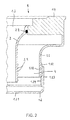
- the drain 1, 1 comprises a pot-shaped housing 1.1, which has a cup-shaped or cup-shaped bottom part 1.2 and at its top an inlet opening 1.3.
- the inlet opening 1.3 is formed in a cover part 1.4, which is liquid-tightly connected to the cup-shaped housing 1.1, preferably welded or glued.
- the bottom part 1.2 has no connection piece for connecting a sewer pipe (not shown). Rather, a corresponding connection piece 1.5 is arranged laterally on the drain housing 1.1.
- the connection piece 1.5 is over a welding or adhesive connection with the drain housing 1.1 and the cover part 1.4 connected.
- the drain 1, 1 'further comprises a dip tube 2, which is insertable via the inlet opening 1.3 in the drain housing 1.1 and defines a smell trap with this.
- the dip tube 2 does not touch the bottom part 1.2 in the installed state. Rather, the dip tube 2 protrudes in the mounted state griskragend, with a radial distance in the cup-shaped bottom part 1.2, wherein the lower end of the dip tube 2 ends at a distance from the bottom of the bottom part 1.2.
- the inlet opening 1.3 is viewed in vertical section stepped. It comprises an upper, annular peripheral shoulder 1.31 into which a sealing foil (not shown) with a gradient in the direction of dip tube 2 can extend.
- the sealing film may be in the form of a first liquid sealant, i.
- a cylindrical support surface is 1.33, which serves to hold the dip tube 2.
- the removable from the drain body 1.1 dip tube 2 has near its upper end an externally arranged annular groove 2.3 for receiving a sealing ring.
- the inserted into the annular groove 2.3 sealing ring 2.4 causes a frictional connection between the dip tube 2 and the drain housing 1.1 or its cover part 1.4.
- the bottom part 1.2 of the drain 1, 1 ' has a substantially planar bottom 1.21 with a conical, projecting into the dip tube 2 bottom portion 1.22.
- the conical bottom section 1.22 improves the deflection of the draining liquid in the region of the bottom 1.21. As a result, a backflow of the outflowing liquid is counteracted at relatively high liquid supply and thus improves the drainage performance.
- the bottom part 1.2 of the process is height-adjustable connected to the housing 1.1.
- the bottom part 1.2 and the drain body 1.1 each have a circular-cylindrical portion 1.11, 1.23, on which threads screwed together 1.12, 1.24 are formed.
- the cup-shaped bottom part 1.2 an internal thread 1.24 and the bottom part associated circular cylindrical section 1.11 of the drain housing 1.1 an external thread 1.12.
- the threaded connection between the bottom part 1.2 and drain housing 1.1 according to the FIGS. 1 and 2 is preferably formed self-sealing, so that there is no liquid-tight connection without an additional sealant, which also allows height adjustment of the bottom part 1.2 relative to the drain body 1.1.
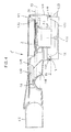
- the height adjustment of the Bottom part opposite to the drain housing is allowed in the Figures 3 and 4 shown.
- the embodiment shown there differs from the embodiment according to the FIGS. 1 and 2 in that on the bottom part 1.2 and the drain body 1.1 locking elements are formed so that the bottom part 1.2 relative to the drain body 1.1 can be adjusted stepwise in height.
- the drain housing 1.1 has a cylindrical, preferably circular cylindrical section 1.11, in which the cup-shaped bottom part 1.2 is inserted. On the inner circumference of the cylindrical housing portion 1.11 an annular groove is formed 1.13. Into the annular groove 1.13, a seal 1.14 in the form of an O-ring made of rubber or the like is used, wherein the seal 1.14 protrudes radially inwardly relative to the annular groove 1.13.
- the cup-shaped, likewise preferably circular cylindrical base part 1.2 has on its outer circumference a plurality of mutually axially spaced annular grooves 1.27, which are assigned to the annular groove of the drain housing 1.1 1.13.
- the annular grooves 1.27 of the bottom part 1.2 are equally spaced from each other.
- the bottom part 1.2 three annular grooves 1.27. It is understood, however, that the height adjustment of the bottom part 1.2 according to the invention is also realized if the bottom part 1.2 would have only two annular grooves 1.27. Likewise, the bottom part 1.27 may also have more than three annular grooves 1.27.
- the annular groove 1.13 of the drain housing 1.1 with the annular seal used therein 1.14 and the grooves 1.27 of the bottom part 1.2 represent locking elements, wherein the seal 1.14 depending on the set position of the bottom part 1.2 relative to the drain body 1.1 in one of the grooves 1.27 of the bottom part 1.2 positively engages.
- the cylindrical portion 1.11 of the drain body 1.1 has a circumferential, radially inwardly projecting shoulder 1.15, on the inside of which the sealing ring 1.14 retaining annular groove is formed 1.13.
- the peripheral outer edge 1.16 of paragraph 1.15 serves as an axial stop for the strap.
- the thickness of the side wall of the cup-shaped bottom part 1.2 according to Figures 3 and 4 increases from the top to the bottom 1.21.
- the bottom part 1.2 thus limits a conically tapering towards the bottom 1.21 cavity.
- the dip tube 2 is in one piece (integrally) formed in the illustrated embodiments.
- the dip tube 2 is unique to the required length shortened.
- the shortening of the dip tube 2 can be carried out by means of a saw or a knife.
- the dip tube 2 a plurality of axially spaced circumferential projections (annular projections) 2.5.
- the projections 2.5 are equally spaced from each other and serve as a guide for a cutting tool if the dip tube 2 is shortened.
- the dip tube 2 is used uncut in the drain housing 1.1.
- the drainage performance of the process can be varied.
- a reduction in the distance between the lower edge of the dip tube 2 and the bottom 1.21 of the bottom part 1.2 leads to a reduction of the annular cross-sectional width and thus to a reduction in the drainage performance of the process.
- the parameters installation height and sealing water level can be set separately from each other in the process according to the invention.
- the drainage performance results from the selected setting (constellation).
- the lower section 2.2 of the dip tube 2 is substantially cylindrical, while the upper section 2.1 widens conically or funnel-shaped toward its upper end.
- the dip tube 2 defines with the bottom part 1.2 and the drain body 1.1 an annular drain channel (annulus) 4, the cross-sectional width increases from bottom to top.
- paragraph 1.32 having recess is formed.
- a grate (not shown) or a grate-bearing attachment (not shown) can be used.
- the inner edge of paragraph 1.32 is at least one Partial circumference of the opening 1.3 formed beveled.
- the bevel 1.34 serves as a support for the dip tube 2, the flange-like end of which has on the outer circumference a chamfer complementary to the bevel formed.
- FIG. 1 illustrated drain housing 1.1 has a transverse to the longitudinal center axis of the connecting piece 1.5 extending overflow edge (barrier water barrier) 1.6.
- overflow edge barrier water barrier
- a flow channel extension 1.7 is formed, which narrows towards the overflow edge 1.6 (see. Fig. 1 ).
- the flow channel extension 1.7 is at least partially formed by a bead formed in the drain housing 1.1 on the inside.
- the drainage channel extension 1.7 is part of a horizontal, disc-shaped outlet channel section 1.8, which is bounded by the dip tube 2 and the drain housing 1.1.
- the volume of this disc-shaped discharge channel section is greater than or equal to the volume within the dip tube 2, which is bounded by an upper horizontal plane H1 extending tangentially to the barrier water barrier 1.6 and by a lower horizontal plane H2 extending tangentially to the lower end of the dip tube 2.
- drain housing 1.1 has a transverse to the longitudinal center axis of the connecting piece 1.5 extending overflow edge (barrier water barrier) 1.6.
- overflow edge barrier water barrier
- the overflow edge 1.6 transversely or perpendicular to the longitudinal center axis of the connecting piece 1.5 considered a height offset 1.61 (see. Fig. 3 ).
- the overflow edge 1.6 is formed lower in its middle section 1.62 than in its sections 1.63, which terminate on the side walls 1.17 of the drainage housing 1.1, which limit the outlet channel leading to the connection piece 1.5.
- the height offset 1.61 is at least 5%, preferably at least 8% of the inner diameter of the connecting piece 1.5.
- barrier barrier walls (bulkheads) 1.18 are formed, which extend in the direction dip tube 2 and on the cylindrical portion of the drain housing 1.1 1.1, 1.1 serves to accommodate the bottom part, end.
- the partitions 1.18 are formed in the region of the height offset 1.61 to the overflow edge (barrier water barrier) 1.6 and the bottom of the drain housing 1.1 and extend substantially vertically and substantially parallel to each other.
- the height of the partitions 1.18 corresponds essentially to the greatest height of the overflow edge 1.63.
- the inlet openings 1.3 facing end faces 1.19 of the bulkheads 1.18 are formed chamfered, the end faces 1.19 fall towards the bottom part 1.2.
- the dashed line H2 denotes the dip tube lower edge.
- the lower edge of the dip tube defines the air passage level of the drain in the case of a water suction caused by vacuum in the sewer.
- the upper dashed line H1 corresponds to the water level in the drain housing 1.1 before a water suction related disturbance, while the dashed line labeled H3 represents the water level after such a disturbance.
Abstract
Description
Die Erfindung betrifft einen Ablauf, insbesondere für bodengleiche Duschen, mit einem topfförmigen Ablaufgehäuse, das einen schalen- oder topfförmig ausgebildeten, anschlussstutzenfreien Bodenteil, einen seitlich angeordneten Anschlussstutzen und an seiner Oberseite eine Zulauföffnung aufweist, und einem Tauchrohr, das über die Zulauföffnung in das Ablaufgehäuse einsetzbar ist und mit diesem einen Geruchverschluss definiert.The invention relates to a sequence, in particular for floor-level showers, with a cup-shaped drain housing having a cup-shaped or cup-shaped, connection piece-free bottom part, a laterally arranged connection piece and at its top an inlet opening, and a dip tube, which via the inlet opening in the drain housing can be used and defines a smell trap with this.
Ein derartiger Ablauf ist beispielsweise aus der
Der zum Bau einer bodengleichen Dusche in einem Badzimmerboden vorhandene oder herstellbare Raum zur Aufnahme eines einen Geruchverschluss aufweisenden Bodenablaufgehäuses ist in der Regel begrenzt. Denn der Betonboden bzw. die Betondecke unterhalb der Dusche sollte aus Gründen der Tragsicherheit und/oder des Brandschutzes nicht übermäßig durchbrochen oder geschwächt werden. Ferner besteht ein Wunsch nach niedrigen Estrichhöhen, insbesondere im Bereich der Altbausanierung. Es wurden daher bereits zahlreiche relativ flach bauende Bodenabläufe mit Geruchverschluss entwickelt.The space available for the construction of a floor-level shower in a bathroom floor or producible space for receiving a odor trap floor drain housing is usually limited. Because of the concrete floor or the concrete ceiling below the shower should not be overly broken or weakened for reasons of security and / or fire safety. Furthermore, there is a desire for low screed heights, especially in the field of old building renovation. Therefore, numerous relatively flat floor drains with odor trap have already been developed.
In vielen Fällen ist jedoch auch ein ausreichend tiefer Einbauraum zur Aufnahme eines Bodenablaufs mit integriertem Geruchverschluss vorhanden, so dass dann die Möglichkeit besteht, die Sperrwasserhöhe im Geruchsverschluss relativ groß zu dimensionieren.In many cases, however, a sufficiently deep installation space for receiving a floor drain with integrated odor trap is available, so that then there is the possibility of relatively large dimensions of the sealing water level in the odor trap.
Der vorliegenden Erfindung liegt die Aufgabe zugrunde, einen Ablauf mit Geruchverschluss insbesondere für bodengleiche Duschen bereitzustellen, der sich an unterschiedliche Einbausituationen flexibel anpassen lässt, so dass seine Bauhöhe, Sperrwasserhöhe sowie Ablaufleistung variabel ist.The present invention has for its object to provide a drain with odor trap especially for floor-level showers, which can be flexibly adapted to different installation situations, so that its height, sealing water level and drain performance is variable.
Diese Aufgabe wird durch einen Ablauf mit den Merkmalen des Anspruchs 1 gelöst.This object is achieved by a sequence with the features of
Der erfindungsgemäße Ablauf ist dadurch gekennzeichnet, dass dessen Bodenteil höhenverstellbar und flüssigkeitsdicht mit dem Ablaufgehäuse verbunden ist.The sequence of the invention is characterized in that the bottom part is height-adjustable and liquid-tightly connected to the drain housing.
Das Tauchrohr ist dabei vorzugsweise so ausgebildet, dass es zur Reduzierung seiner axialen Länge durch Abtrennen eines Rohrabschnitts gekürzt werden muss. Das aus dem Ablaufgehäuse herausnehmbare Tauchrohr, das vorzugsweise einteilig ausgeführt ist, kann so bei Bedarf auf die erforderliche Länge gekürzt werden, beispielsweise mittels einer Säge.The dip tube is preferably formed so that it must be cut to reduce its axial length by separating a pipe section. The removable from the drain housing dip tube, which is preferably made in one piece, can be shortened if necessary to the required length, for example by means of a saw.
Der Vorteil des erfindungsgemäßen Ablaufes liegt insbesondere darin, dass dieser nicht wie ein herkömmlicher Ablauf feste Parameter bezüglich der Einbauhöhe, Sperrwasserhöhe und Ablaufleistung aufweist, sondern diesbezüglich vor Ort auf einfache Weise variabel einstellbar ist. Die Einstellung kann dabei in Abhängigkeit des jeweils im Vordergrund stehenden Bedürfnisses vorgenommen werden. Ist beispielsweise eine möglichst geringe Bauhöhe (Gesamthöhe) gefordert, so kann dies durch entsprechende Höhenverstellung des Bodenteils gegenüber dem Ablaufgehäuse realisiert werden. Die axiale Länge des Tauchrohrs ist dann durch Kürzen desselben an die eingestellte Gesamthöhe anpassbar, wobei insoweit eine bei geringer Gesamthöhe des Ablaufs maximierte Sperrwasserhöhe oder eine maximierte Ablaufleistung bzw. ein Kompromiss zwischen maximierter Sperrwasserhöhe und maximierter Ablaufleistung eingestellt werden kann. Die Einstellung des erfindungsgemäßen Ablaufs wird in Abhängigkeit des Parameters vorgenommen, der in der jeweiligen Situation gerade wichtig ist.The advantage of the sequence according to the invention is, in particular, that it does not have fixed parameters with regard to the installation height, sealing water level and drainage capacity, as in the case of a conventional drainage, but can be set variably in a simple manner in this regard in the field. The setting can be made depending on the need in each case in the foreground. If, for example, the lowest possible height (total height) is required, this can be done by corresponding height adjustment of the bottom part relative to the drain housing can be realized. The axial length of the dip tube is then adaptable by shortening it to the set total height, in which respect a maximum total height of the drain maximized sealing water level or a maximized drainage performance or a compromise between maximized sealing water level and maximized drainage capacity can be adjusted. The setting of the sequence according to the invention is carried out as a function of the parameter which is just important in the respective situation.
Um eine einfache, stufenlose Höhenverstellung des Bodenteils gegenüber dem Ablaufgehäuse zu ermöglichen, sieht eine bevorzugte Ausgestaltung des erfindungsgemäßen Ablaufs vor, dass der Bodenteil und das Ablaufgehäuse jeweils mit einem Gewinde versehen sind, die miteinander verschraubbar sind.In order to enable a simple, continuous height adjustment of the bottom part relative to the drain body, a preferred embodiment of the sequence according to the invention provides that the bottom part and the drain body are each provided with a thread, which are screwed together.
Das Schraubgewinde zwischen Bodenteil und Ablaufgehäuse ist dabei vorzugsweise so ausgebildet, dass es ohne den Einsatz einer zusätzlichen Dichtung eine Dichtungsfunktion bezüglich Flüssigkeiten aufweist. Zweckmäßigerweise kann jedoch auch gemäß einer alternativen Ausgestaltung zwischen dem Bodenteil und dem Ablaufgehäuse eine ringförmige Dichtung angeordnet sein und/oder der Bodenteil einen eine ringförmige Dichtfläche definierenden Kragen aufweisen.The screw thread between the bottom part and drain housing is preferably designed so that it has a sealing function with respect to liquids without the use of an additional seal. Conveniently, however, may be arranged according to an alternative embodiment between the bottom part and the drain housing, an annular seal and / or the bottom part have an annular sealing surface defining collar.
Alternativ zu der Ausbildung eines Schraubgewindes zwischen Ablaufgehäuse und dessen Bodenteil sieht eine andere vorteilhafte Ausgestaltung der Erfindung vor, dass an dem Bodenteil und dem Ablaufgehäuse Rastelemente ausgebildet sind, so dass der Bodenteil relativ zu dem restlichen Ablaufgehäuse stufenartig in der Höhe verstellbar ist. Bei dieser alternativen Ausgestaltung des erfindungsgemäßen Ablaufs ist vorzugsweise zwischen dem Bodenteil und dem Ablaufgehäuse eine ringförmige Dichtung angeordnet.As an alternative to the formation of a screw thread between drain housing and the bottom part, another advantageous embodiment of the invention provides that formed on the bottom part and the drain housing locking elements are, so that the bottom part is adjustable relative to the rest of the drain housing stepwise in height. In this alternative embodiment of the process according to the invention, an annular seal is preferably arranged between the bottom part and the drain housing.
Um die Länge des Tauchrohrs ebenfalls auf einfache Weise anpassen zu können, sieht eine weitere bevorzugte Ausgestaltung des erfindungsgemäßen Ablaufs vor, dass das Tauchrohr an seiner Außenseite mehrere axial beabstandete Ringnuten und/oder Ringvorsprünge aufweist. Die Ringnuten bzw. Ringvorsprünge dienen als Führung für ein Schneidwerkzeug, beispielsweise eine Säge, und erleichtern die Herstellung einer rechtwinklig zur Vertikalachse des Tauchrohrs verlaufenden Schnittebene, so dass die ringförmige Unterkante des gekürzten Tauchrohrs in dessen Einbaulage im Wesentlichen horizontal angeordnet ist.To be able to adjust the length of the dip tube also in a simple manner, provides a further preferred embodiment of the sequence according to the invention that the dip tube has on its outside a plurality of axially spaced annular grooves and / or annular projections. The annular grooves or annular projections serve as a guide for a cutting tool, such as a saw, and facilitate the production of a perpendicular to the vertical axis of the dip tube extending cutting plane, so that the annular lower edge of the shortened dip tube is arranged substantially horizontally in its installed position.
Nach einer weiteren bevorzugte Ausgestaltung des erfindungsgemäßen Ablaufs ist vorgesehen, dass das Tauchrohr mit dem Bodenteil und/oder dem Ablaufgehäuse einen ringförmigen Ablaufkanal definiert, dessen Querschnittsweite von unten nach oben zunimmt. Diese Ausgestaltung begünstigt einen zuverlässigen Flüssigkeitsabfluss und wirkt zudem einer unerwünschten Absaugung des Sperrwassers im Geruchverschluss bei einem Unterdruck in der am Ablauf angeschlossenen Abwasserleitung entgegen.According to a further preferred embodiment of the sequence according to the invention, it is provided that the dip tube with the bottom part and / or the drain housing defines an annular drainage channel whose cross-sectional width increases from bottom to top. This embodiment promotes reliable liquid drainage and also counteracts unwanted suction of the sealing water in the odor trap at a negative pressure in the sewer connected to the drain.
Eine weitere vorteilhafte Ausgestaltung des erfindungsgemäßen Ablaufs sieht vor, dass das Ablaufgehäuse innen eine quer zur Längsmittelachse des Anschlussstutzens verlaufende, vertikal vorstehende Überlaufkante aufweist, die quer oder rechtwinklig zur Längsmittelachse des Anschlussstutzens betrachtet einen Höhenversatz aufweist. Die Überlaufkante bildet eine Sperrwasserbarriere, die ein Abfließen von Sperrwasser infolge eines Saugeffekts in der angeschlossenen Abwasserleitung begrenzt und somit Funktion des Geruchverschlusses trotz des Saugeffekts sicherstellt.A further advantageous embodiment of the sequence according to the invention provides that the drain housing inside a transverse to the longitudinal central axis of the connecting piece extending, vertically projecting overflow edge, viewed transversely or at right angles to the longitudinal central axis of the connecting piece has a height offset. The overflow edge forms a barrier water barrier, which limits a drainage of sealing water due to a suction effect in the connected sewer line and thus ensures function of the odor trap despite the suction effect.
Der Höhenversatz beeinflusst die Fließrichtung von aus dem Ablauf abfließendem Wasser, insbesondere die Fließrichtung eines sich dabei gegebenenfalls bildenden Wasser-Luftgemisches. Das Wasser-Luftgemisch wird dabei in den Bereich der tiefsten Stelle der Sperrwasserbarriere (Überlaufkante) geleitet, so dass sich ein Luftspalt oder Luftkanal bildet, der das Vakuum in der Abwasserleitung aufhebt und somit einen Verlust der Sperrwirkung des Geruchsverschlusses verhindert.The height offset influences the direction of flow of water flowing out of the drain, in particular the direction of flow of a possibly forming water-air mixture. The water-air mixture is thereby passed into the region of the lowest point of the barrier barrier (overflow edge), so that an air gap or air channel is formed, which cancels the vacuum in the sewer line and thus prevents loss of the blocking effect of the odor trap.
Hinsichtlich der Beeinflussung der Fließrichtung des aus dem Ablauf abfließenden Wassers bzw. des Wasser-Luftgemisches ist es ferner vorteilhaft, wenn gemäß einer weiteren Ausgestaltung des erfindungsgemäßen Ablaufs an der Überlaufkante (Sperrwasserbarriere) mindestens eine sich in Richtung Tauchrohr erstreckende Trenn- oder Schottwand angeformt ist. Vorzugsweise ist die Trennwand (Schottwand) im Bereich des Höhenversatzes an die Überlaufkante angeformt und erstreckt sich im Wesentlichen vertikal. Beim Abfließen von Wasser aufgrund eines durch ein Vakuum in der Abwasserleitung bedingten Saugeffektes bewirkt die Trennwand eine Trennung des abfließenden Wassers vom Wasser-Luftgemisch bzw. von dem sich im Wasserstrom ausbildenden Luftkanal, so dass durch die Trennwand mehr Wasser im Ablaufgehäuse zurückgehalten wird.With regard to influencing the flow direction of the effluent from the drain water or the water-air mixture, it is also advantageous if according to a further embodiment of the invention at the overflow edge (barrier barrier) at least one extending in the direction of dip tube separating or bulkhead is formed. Preferably, the partition (bulkhead) is formed in the region of the height offset to the overflow edge and extends substantially vertically. When water flows due to a caused by a vacuum in the sewer suction effect the partition wall causes a separation of the effluent water from the water-air mixture or of the water in the stream forming air duct so that more water is retained in the drain housing by the partition.
Eine weitere vorteilhafte Ausgestaltung des erfindungsgemäßen Ablaufs besteht darin, dass in Ablaufrichtung gesehen vor der Überlaufkante eine Ablaufkanalerweiterung ausgebildet ist, die sich zur Überlaufkante hin verjüngt. Die Ablaufkanalerweiterung ist vorzugsweise Teil eines horizontalen, scheibenförmigen Ablaufkanalabschnitts, der durch das Tauchrohr und das Ablaufgehäuse begrenzt ist, wobei das Volumen dieses scheibenförmigen Ablaufkanalabschnitts größer oder gleich dem Volumen innerhalb des Tauchrohrs ist, welches durch eine obere, tangential zur Überlaufkante verlaufende Horizontalebene und durch eine untere, tangential zum unteren Ende des Tauchrohrs verlaufende Horizontalebene begrenzt ist. Durch diese Ausgestaltung wird sichergestellt, dass das relativ kleine Wasservolumen innerhalb des Tauchrohres bei einem Absaugen infolge eines Vakuums in der angeschlossenen Abwasserleitung teilweise oder ganz in dem Volumen des horizontalen Ablaufkanalscheibenabschnitts aufgenommen wird und nach Wegfall des Vakuums zurückfließen kann, so dass stets genügend Sperrwasser in dem Ablauf verbleibt und damit die Sperrfunktion des Geruchverschlusses sichergestellt ist. Die Ablaufkanalerweiterung bzw. das besagte Volumen des horizontalen Ablaufkanalscheibenabschnitts stellen eine Absaugsicherung dar, die es ermöglicht, den Ablauf besonders flach auszubilden, so dass er eine relativ niedrige Gesamthöhe aufweist.A further advantageous embodiment of the process according to the invention consists in that, seen in the direction of flow, a flow channel enlargement is formed in front of the overflow edge which tapers towards the overflow edge. The drainage channel extension is preferably part of a horizontal, disc-shaped drainage passage section delimited by the dip tube and the drainage housing, the volume of this disc-shaped drainage passage section being greater than or equal to the volume within the dip tube, passing through an upper horizontal plane tangential to the overflow edge and through one lower, tangential to the lower end of the dip tube extending horizontal plane is limited. By this configuration it is ensured that the relatively small volume of water within the dip tube is partially or completely absorbed in the volume of the horizontal drain channel portion at a suction due to a vacuum in the connected sewer and can flow back to the absence of the vacuum, so that always enough sealing water in the Drain remains and thus the blocking function of the odor trap is ensured. The drainage channel extension or the said volume of the horizontal drainage channel disk section represent a suction protection, which makes it possible to form the drain particularly flat, so that it has a relatively low overall height.
Weitere bevorzugte Ausgestaltungen des erfindungsgemäßen Ablaufs sind in den Unteransprüchen angegeben.Further preferred embodiments of the process according to the invention are specified in the subclaims.
Nachfolgend wird die Erfindung anhand einer mehrere Ausführungsbeispiele darstellenden Zeichnung näher erläutert. Es zeigen:
- Fig. 1
- eine vertikale Schnittansicht eines erfindungs- gemäßen Ablaufs;
- Fig. 2
- eine vergrößerte Detailansicht der
Fig. 1 ; - Fig. 3
- ein zweites Ausführungsbeispiel eines erfindungs- gemäßen Ablaufs in vertikaler, perspektivischer Schnittansicht; und
- Fig. 4
- eine weitere vertikale Schnittansicht des Ablaufs der
Fig. 3 .
- Fig. 1
- a vertical sectional view of an inventive process;
- Fig. 2
- an enlarged detail view of the
Fig. 1 ; - Fig. 3
- A second embodiment of an inventive sequence in a vertical, perspective sectional view; and
- Fig. 4
- another vertical sectional view of the flow of the
Fig. 3 ,
Der in der Zeichnung dargestellte Ablauf 1, 1' ist für den Einbau in einen Estrich- oder Betonboden bestimmt, beispielsweise um einen Ablauf für eine bodengleiche Dusche herzustellen.The sequence shown in the
Der Ablauf 1, 1' umfasst ein topfförmiges Gehäuse 1.1, das einen schalen- oder topfförmig ausgebildeten Bodenteil 1.2 und an seiner Oberseite eine Zulauföffnung 1.3 aufweist. Die Zulauföffnung 1.3 ist in einem Deckelteil 1.4 ausgebildet, der mit dem topfförmigen Gehäuse 1.1 flüssigkeitsdicht verbunden, vorzugsweise verschweißt oder verklebt ist. Der Bodenteil 1.2 hat keinen Anschlussstutzen zum Anschluss einer Abwasserleitung (nicht gezeigt). Vielmehr ist ein entsprechender Anschlussstutzen 1.5 seitlich am Ablaufgehäuse 1.1 angeordnet. Der Anschlussstutzen 1.5 ist über eine Schweiß- oder Klebeverbindung mit dem Ablaufgehäuse 1.1 und dem Deckelteil 1.4 verbunden.The
Der Ablauf 1, 1' umfasst ferner ein Tauchrohr 2, das über die Zulauföffnung 1.3 in das Ablaufgehäuse 1.1 einsetzbar ist und mit diesem einen Geruchverschluss definiert. Das Tauchrohr 2 berührt den Bodenteil 1.2 im eingebauten Zustand nicht. Vielmehr ragt das Tauchrohr 2 im montierten Zustand freikragend, mit radialem Abstand in den schalenförmigen Bodenteil 1.2, wobei das untere Ende des Tauchrohres 2 mit Abstand zum Boden des Bodenteils 1.2 endet. Die Zulauföffnung 1.3 ist im Vertikalschnitt betrachtet stufenförmig ausgebildet. Sie umfasst einen oberen, ringförmig umlaufenden Absatz 1.31, in den sich eine Dichtungsfolie (nicht gezeigt) mit Gefälle in Richtung Tauchrohr 2 erstrecken kann. Die Dichtungsfolie kann beispielsweise in Form einer zunächst flüssigen Dichtungsmasse, d.h. einer so genannten Flüssigfolie aufgetragen werden. Unterhalb des oberen Absatzes 1.31 ist ein zweiter, ebenfalls ringförmig umlaufender Absatz 1.32 im Deckelteil 1.4 des Ablaufs ausgebildet. Der zweite Absatz 1.32 dient der formschlüssigen Aufnahme eines Rahmens bzw. Adapters (nicht gezeigt), in den wiederum ein Ablaufrost eingesetzt wird.The
Unterhalb des zweiten Absatzes 1.32 ist eine zylindrische Stützfläche 1.33 ausgebildet, die der Halterung des Tauchrohrs 2 dient. Das aus dem Ablaufgehäuse 1.1 herausnehmbare Tauchrohr 2 weist nahe seinem oberen Ende eine außenseitig angeordnete Ringnut 2.3 zur Aufnahme eines Dichtungsringes auf. Der in die Ringnut 2.3 eingesetzte Dichtungsring 2.4 bewirkt eine reibschlüssige Verbindung zwischen dem Tauchrohr 2 und dem Ablaufgehäuse 1.1 bzw. dessen Deckelteil 1.4.Below the second paragraph 1.32, a cylindrical support surface is 1.33, which serves to hold the
Der Bodenteil 1.2 des Ablaufs 1, 1' hat einen im Wesentlichen eben ausgebildeten Boden 1.21 mit einem kegelförmigen, in das Tauchrohr 2 hineinragenden Bodenabschnitt 1.22. Der kegelförmige Bodenabschnitt 1.22 verbessert die Umlenkung der ablaufenden Flüssigkeit im Bereich des Bodens 1.21. Hierdurch wird bei relativ hohem Flüssigkeitszulauf einem Rückstau der abfließenden Flüssigkeit entgegengewirkt und damit die Ablaufleistung verbessert.The bottom part 1.2 of the
Der Bodenteil 1.2 des Ablaufs ist höhenverstellbar mit dem Gehäuse 1.1 verbunden. Zu diesem Zweck weisen das Bodenteil 1.2 und das Ablaufgehäuse 1.1 jeweils einen kreiszylindrischen Abschnitt 1.11, 1.23 auf, an denen miteinander verschraubbare Gewinde 1.12, 1.24 ausgebildet sind. In dem in den
Die Gewindeverbindung zwischen Bodenteil 1.2 und Ablaufgehäuse 1.1 gemäß den
Eine weitere Möglichkeit zur Realisierung einer flüssigkeitsdichten Verbindung, die eine Höhenverstellung des Bodenteils gegenüber dem Ablaufgehäuse gestattet, ist in den
Das Ablaufgehäuse 1.1 weist einen zylindrischen, vorzugsweise kreiszylindrischen Abschnitt 1.11 auf, in den der schalenförmige Bodenteil 1.2 eingesetzt ist. Am Innenumfang des zylindrischen Gehäuseabschnitts 1.11 ist eine Ringnut 1.13 ausgebildet. In die Ringnut 1.13 ist eine Dichtung 1.14 in Form eines O-Ring aus Gummi oder dergleichen eingesetzt, wobei die Dichtung 1.14 gegenüber der Ringnut 1.13 radial nach innen vorsteht. Der schalenförmige, ebenfalls vorzugsweise kreiszylindrische Bodenteil 1.2 weist auf seinem Außenumfang mehrere, zueinander axial beabstandete Ringnuten 1.27 auf, die der Ringnut 1.13 des Ablaufgehäuses 1.1 zugeordnet sind. Die Ringnuten 1.27 des Bodenteils 1.2 sind gleichmäßig zueinander beabstandet. In dem dargestellten Ausführungsbeispiel weist der Bodenteil 1.2 drei Ringnuten 1.27 auf. Es versteht sich allerdings, dass die erfindungsgemäße Höhenverstellbarkeit des Bodenteils 1.2 auch verwirklicht wird, wenn der Bodenteil 1.2 nur zwei Ringnuten 1.27 aufweisen würde. Ebenso kann der Bodenteil 1.27 auch mehr als drei Ringnuten 1.27 aufweisen. Die Ringnut 1.13 des Ablaufgehäuses 1.1 mit der darin eingesetzten ringförmigen Dichtung 1.14 und die Nuten 1.27 des Bodenteils 1.2 stellen Rastelemente dar, wobei die Dichtung 1.14 je nach der eingestellten Position des Bodenteils 1.2 relativ zu dem Ablaufgehäuse 1.1 in eine der Nuten 1.27 des Bodenteils 1.2 formschlüssig eingreift. An dem zylindrischen Abschnitt 1.11 des Ablaufgehäuses 1.1 ist ein Spannband (nicht gezeigt) angebracht, mittels dem der Bodenteil 1.2 von außen an dem Ablaufgehäuse 1.1 klemmend fixiert ist. Der zylindrische Abschnitt 1.11 des Ablaufgehäuses 1.1 hat einen umlaufenden, radial nach innen vorspringenden Absatz 1.15, an dessen Innenseite die den Dichtungsring 1.14 haltende Ringnut 1.13 ausgebildet ist. Die umlaufende Außenkante 1.16 des Absatzes 1.15 dient als axialer Anschlag für das Spannband.The drain housing 1.1 has a cylindrical, preferably circular cylindrical section 1.11, in which the cup-shaped bottom part 1.2 is inserted. On the inner circumference of the cylindrical housing portion 1.11 an annular groove is formed 1.13. Into the annular groove 1.13, a seal 1.14 in the form of an O-ring made of rubber or the like is used, wherein the seal 1.14 protrudes radially inwardly relative to the annular groove 1.13. The cup-shaped, likewise preferably circular cylindrical base part 1.2 has on its outer circumference a plurality of mutually axially spaced annular grooves 1.27, which are assigned to the annular groove of the drain housing 1.1 1.13. The annular grooves 1.27 of the bottom part 1.2 are equally spaced from each other. In the illustrated embodiment, the bottom part 1.2 three annular grooves 1.27. It is understood, however, that the height adjustment of the bottom part 1.2 according to the invention is also realized if the bottom part 1.2 would have only two annular grooves 1.27. Likewise, the bottom part 1.27 may also have more than three annular grooves 1.27. The annular groove 1.13 of the drain housing 1.1 with the annular seal used therein 1.14 and the grooves 1.27 of the bottom part 1.2 represent locking elements, wherein the seal 1.14 depending on the set position of the bottom part 1.2 relative to the drain body 1.1 in one of the grooves 1.27 of the bottom part 1.2 positively engages. On the cylindrical portion of the drain housing 1.1 1.11 (not shown), a strap, by means of which the bottom part 1.2 is fixed by clamping from the outside to the drain body 1.1. The cylindrical portion 1.11 of the drain body 1.1 has a circumferential, radially inwardly projecting shoulder 1.15, on the inside of which the sealing ring 1.14 retaining annular groove is formed 1.13. The peripheral outer edge 1.16 of paragraph 1.15 serves as an axial stop for the strap.
Die Dicke der Seitenwand des schalenförmigen Bodenteils 1.2 gemäß den
Das Tauchrohr 2 ist in den dargestellten Ausführungsbeispielen einteilig (einstückig) ausgebildet. Um die Länge des Tauchrohrs 2 an die über die Höhenverstellung des Bodenteils 1.2 eingestellte Gesamthöhe des Ablaufs 1, 1' anpassen bzw. um die Sperrwasserhöhe oder die Ablaufleistung in Abhängigkeit der an den Ablauf gestellten Anforderungen einzustellen, wird das Tauchrohr 2 einmalig auf die erforderliche Länge gekürzt. Das Kürzen des Tauchrohrs 2 kann mittels einer Säge oder einem Messer durchgeführt werden.The
Bei dem in
Um eine maximale Sperrwasserhöhe einzustellen, wird das Tauchrohr 2 ungekürzt in das Ablaufgehäuse 1.1 eingesetzt. Durch Einstellen der Höhe des Bodenteils 1.2 gegenüber dem Ablaufgehäuse 1.1 und dem darin eingesetzten Tauchrohr 2 lässt sich die Ablaufleistung des Ablaufs variieren. Eine Verringerung des Abstandes zwischen der Unterkante des Tauchrohrs 2 und dem Boden 1.21 des Bodenteils 1.2 führt zu einer Verringerung der ringförmigen Querschnittsweite und damit zu einer Verringerung der Ablaufleistung des Ablaufs. Die Parameter Einbauhöhe und Sperrwasserhöhe lassen sich bei dem erfindungsgemäßen Ablauf separat voneinander einstellen. Die Ablaufleistung ergibt sich aus der gewählten Einstellung (Konstellation).In order to set a maximum sealing water level, the
Der untere Abschnitt 2.2 des Tauchrohrs 2 ist im Wesentlichen zylindrisch ausgebildet, während sich der obere Abschnitt 2.1 zu seinem oberen Ende hin konisch oder trichterförmig erweitert. Das Tauchrohr 2 definiert mit dem Bodenteil 1.2 bzw. dem Ablaufgehäuse 1.1 einen ringförmigen Ablaufkanal (Ringraum) 4, dessen Querschnittsweite von unten nach oben zunimmt.The lower section 2.2 of the
In dem Deckelteil 1.4 des Ablaufgehäuses 1.1 ist eine einen Absatz 1.32 aufweisende Vertiefung eingeformt. In die Vertiefung, die vorzugsweise kreiszylindrisch ausgebildet ist, kann ein Rost (nicht gezeigt) bzw. ein den Rost tragender Aufsatz (nicht gezeigt) eingesetzt werden. Die innere Kante des Absatzes 1.32 ist zumindest über einen Teilumfang der Öffnung 1.3 gefast ausgebildet. Die Fase 1.34 dient als Auflager für das Tauchrohr 2, deren flanschartiges Ende am Außenumfang eine zu der Fase komplementär ausgebildete Abschrägung aufweist.In the cover part 1.4 of the drain body 1.1 a paragraph 1.32 having recess is formed. In the recess, which is preferably circular cylindrical, a grate (not shown) or a grate-bearing attachment (not shown) can be used. The inner edge of paragraph 1.32 is at least one Partial circumference of the opening 1.3 formed beveled. The bevel 1.34 serves as a support for the
Das in
Die Ablaufkanalerweiterung 1.7 ist Teil eines horizontalen, scheibenförmigen Ablaufkanalabschnitts 1.8 ist, der durch das Tauchrohr 2 und das Ablaufgehäuse 1.1 begrenzt ist. Das Volumen dieses scheibenförmigen Ablaufkanalabschnitts ist größer/gleich dem Volumen innerhalb des Tauchrohrs 2, welches durch eine obere, tangential zur Sperrwasserbarriere 1.6 verlaufende Horizontalebene H1 und durch eine untere, tangential zum unteren Ende des Tauchrohrs 2 verlaufende Horizontalebene H2 begrenzt ist.The drainage channel extension 1.7 is part of a horizontal, disc-shaped outlet channel section 1.8, which is bounded by the
Auch das in den
An der Sperrwasserbarriere sind Trennwände (Schottwände) 1.18 angeformt, die sich in Richtung Tauchrohr 2 erstrecken und an dem zylindrischen Abschnitt 1.11 des Ablaufgehäuses 1.1, der der Aufnahme des Bodenteils 1.2 dient, enden. Die Trennwände 1.18 sind im Bereich des Höhenversatzes 1.61 an die Überlaufkante (Sperrwasserbarriere) 1.6 und den Boden des Ablaufgehäuses 1.1 angeformt und erstrecken sich im Wesentlichen vertikal sowie im Wesentlichen parallel zueinander. Die Höhe der Trennwände 1.18 entspricht im Wesentlichen der größten Höhe der Überlaufkante 1.63. Die der Zulauföffnung 1.3 zugewandten Stirnseiten 1.19 der Schottwände 1.18 sind abgeschrägt ausgebildet, wobei die Stirnseiten 1.19 in Richtung Bodenteil 1.2 abfallen.At the barrier barrier walls (bulkheads) 1.18 are formed, which extend in the
In
Die Ausführung der vorliegenden Erfindung ist nicht auf die vorstehend beschriebenen Ausführungsbeispiele beschränkt. Vielmehr sind zahlreiche Varianten möglich, die auch bei von den Ausführungsbeispielen abweichender Gestaltung von der in den beigefügten Ansprüchen angegebenen Erfindung Gebrauch machen.The embodiment of the present invention is not limited to the above-described embodiments. Rather, numerous variants are possible, which make use even in deviating from the embodiments of the invention specified in the appended claims invention.
Claims (15)
dadurch gekennzeichnet, dass das Tauchrohr (2) so ausgebildet ist, dass es zur Reduzierung seiner axialen Länge durch Abtrennen eines Tauchrohrabschnitts (2.2) gekürzt werden muss.Drain according to claim 1,
characterized in that the dip tube (2) is formed so that it must be reduced to reduce its axial length by separating a dip tube section (2.2).
dadurch gekennzeichnet, dass der Bodenteil (1.2) und das Ablaufgehäuse (1.1) jeweils mit einem Gewinde (1.12, 1.24) versehen sind, die miteinander verschraubbar sind.Process according to claim 1 or 2,
characterized in that the bottom part (1.2) and the drain body (1.1) are each provided with a thread (1.12, 1.24), which are screwed together.
dadurch gekennzeichnet, dass an dem Bodenteil (1.2) und dem Ablaufgehäuse (1.1) Rastelemente (1.13, 1.27) ausgebildet sind, so dass der Bodenteil (1.2) relativ zu dem Ablaufgehäuse (1.1) stufenartig in der Höhe verstellbar ist.Process according to claim 1 or 2,
characterized in that formed on the bottom part (1.2) and the drain housing (1.1) locking elements (1.13, 1.27) are, so that the bottom part (1.2) relative to the drain housing (1.1) is adjustable in height in a stepwise manner.
dadurch gekennzeichnet, dass zwischen dem Bodenteil (1.2) und dem Ablaufgehäuse (1.1) eine ringförmige Dichtung (1.14) angeordnet ist, wobei vorzugsweise eine Ringnut (1.13) am Ablaufgehäuse (1.1) ausgebildet ist, in welche die Dichtung (1.14) eingesetzt ist.Process according to one of claims 1 to 4,
characterized in that between the bottom part (1.2) and the drain housing (1.1) an annular seal (1.14) is arranged, wherein preferably an annular groove (1.13) on the drain housing (1.1) is formed, in which the seal (1.14) is inserted.
gekennzeichnet durch ein Spannband, mittels dem der Bodenteil (1.2) an dem Ablaufgehäuse (1.1) klemmend fixierbar ist.Process according to one of claims 1 to 5,
characterized by a strap, by means of which the bottom part (1.2) to the drain housing (1.1) is clamped fixable.
dadurch gekennzeichnet, dass das Tauchrohr (2) mehrere axial beabstandete Ringnuten und/oder Ringvorsprünge (2.5) aufweist.Process according to one of claims 1 to 6,
characterized in that the dip tube (2) has a plurality of axially spaced annular grooves and / or annular projections (2.5).
dadurch gekennzeichnet, dass das Tauchrohr (2) mit radialem Abstand freikragend in den Bodenteil (1.2) des Ablaufgehäuses (1.1) hineinragt, so dass das Tauchrohr (2) und der Bodenteil (1.2) des Ablaufgehäuses (1.1) zusammen einen Ringraum begrenzen.Process according to one of claims 1 to 7,
characterized in that the dip tube (2) with free radial projection protrudes into the bottom part (1.2) of the drain housing (1.1), so that the dip tube (2) and the bottom part (1.2) of the drain housing (1.1) together define an annular space.
dadurch gekennzeichnet, dass das Tauchrohr (2) mit dem Bodenteil (1.2) und/oder dem Ablaufgehäuse (1.2) einen ringförmigen Ablaufkanal (4) definiert, dessen Querschnittsweite von unten nach oben zunimmt.Process according to one of claims 1 to 8,
characterized in that the dip tube (2) with the bottom part (1.2) and / or the drain housing (1.2) defines an annular discharge channel (4) whose cross-sectional width increases from bottom to top.
dadurch gekennzeichnet, dass das Ablaufgehäuse (1.1) innen eine quer oder rechtwinklig zur Längsmittelachse des Anschlussstutzens (1.5) verlaufende, vertikal vorstehende Sperrwasserbarriere (1.6) aufweist, die vorzugsweise einen Höhenversatz (1.61) aufweist.Process according to one of claims 1 to 9,
characterized in that the drain housing (1.1) inside a transverse or perpendicular to the longitudinal central axis of the connecting piece (1.5) extending, vertically projecting barrier barrier (1.6), which preferably has a height offset (1.61).
dadurch gekennzeichnet, dass an der Sperrwasserbarriere (1.6) mindestens eine sich in Richtung Tauchrohr (2) erstreckende Trennwand (1.18) angeformt ist.Drain according to claim 10,
characterized in that at least one in the direction of dip tube (2) extending partition wall (1.18) is integrally formed on the barrier water barrier (1.6).
dadurch gekennzeichnet, dass die Trennwand (1.18) im Bereich des Höhenversatzes (1.61) an die Sperrwasserbarriere (1.6) angeformt ist und sich im Wesentlichen vertikal erstreckt.Drain according to claim 11,
characterized in that the partition wall (1.18) in the region of the height offset (1.61) is integrally formed on the barrier water barrier (1.6) and extends substantially vertically.
dadurch gekennzeichnet, dass der Höhenversatz (1.61) der Sperrwasserbarriere (1.6) mindestens 5%, vorzugsweise mindestens 8% des Innendurchmessers des Anschlussstutzens (1.5) beträgt.Process according to one of claims 10 to 12,
characterized in that the height offset (1.61) of the barrier water barrier (1.6) at least 5%, preferably at least 8% of the inner diameter of the connecting piece (1.5).
dadurch gekennzeichnet, dass in Ablaufrichtung gesehen vor der Sperrwasserbarriere (1.6) eine Ablaufkanalerweiterung (1.7) ausgebildet ist, die sich zur Sperrwasserbarriere (1.6) hin verjüngt.Process according to one of claims 10 to 13,
characterized in that seen in the direction of drainage in front of the barrier barrier (1.6) a drainage channel extension (1.7) is formed, which tapers to the barrier water barrier (1.6).
dadurch gekennzeichnet, dass der Bodenteil (1.2) einen kegelförmigen Bodenabschnitt (1.22) aufweist, der in Richtung Tauchrohr (2) vorsteht und von dem Tauchrohr umgeben ist.Process according to one of claims 1 to 14,
characterized in that the bottom part (1.2) has a conical bottom portion (1.22) projecting towards the dip tube (2) and is surrounded by the dip tube.
Priority Applications (5)
| Application Number | Priority Date | Filing Date | Title |
|---|---|---|---|
| DK09171194.5T DK2305905T3 (en) | 2009-09-24 | 2009-09-24 | Floors with variable installation height |
| PL09171194T PL2305905T3 (en) | 2009-09-24 | 2009-09-24 | Floor drain with variable height |
| ES09171194T ES2395445T3 (en) | 2009-09-24 | 2009-09-24 | Sump with modifiable installation height |
| EP09171194A EP2305905B1 (en) | 2009-09-24 | 2009-09-24 | Floor drain with variable height |
| PT91711945T PT2305905E (en) | 2009-09-24 | 2009-09-24 | Floor drain with variable height |
Applications Claiming Priority (1)
| Application Number | Priority Date | Filing Date | Title |
|---|---|---|---|
| EP09171194A EP2305905B1 (en) | 2009-09-24 | 2009-09-24 | Floor drain with variable height |
Publications (2)
| Publication Number | Publication Date |
|---|---|
| EP2305905A1 true EP2305905A1 (en) | 2011-04-06 |
| EP2305905B1 EP2305905B1 (en) | 2012-10-31 |
Family
ID=41682604
Family Applications (1)
| Application Number | Title | Priority Date | Filing Date |
|---|---|---|---|
| EP09171194A Active EP2305905B1 (en) | 2009-09-24 | 2009-09-24 | Floor drain with variable height |
Country Status (5)
| Country | Link |
|---|---|
| EP (1) | EP2305905B1 (en) |
| DK (1) | DK2305905T3 (en) |
| ES (1) | ES2395445T3 (en) |
| PL (1) | PL2305905T3 (en) |
| PT (1) | PT2305905E (en) |
Cited By (5)
| Publication number | Priority date | Publication date | Assignee | Title |
|---|---|---|---|---|
| DE102012110223A1 (en) * | 2012-10-25 | 2014-04-30 | Mepa - Pauli Und Menden Gmbh | Drain assembly installed in e.g. ground level shower area, has discharge pipe that is installed above drainage plane defined by upper edge of outlet opening of drain element, and is connected to outlet opening end of drain housing |
| DE102013102379A1 (en) * | 2013-03-11 | 2014-09-11 | Mepa-Pauli Und Menden Gmbh | drain arrangement |
| CN104060679A (en) * | 2014-06-30 | 2014-09-24 | 佛山市浪鲸洁具有限公司 | Drainer |
| FR3016177A1 (en) * | 2014-01-08 | 2015-07-10 | Eiffage Construction | RECOVERY FLOOR SIPHON, RECOVERY FLUE-SIPHON, AND METHOD OF MAKING SAME |
| WO2015135728A1 (en) * | 2014-03-14 | 2015-09-17 | Viega Gmbh & Co. Kg | Drain fitting for a floor drainage gully, and floor drainage gully having such a drain fitting |
Citations (6)
| Publication number | Priority date | Publication date | Assignee | Title |
|---|---|---|---|---|
| GB2094847A (en) * | 1981-03-12 | 1982-09-22 | Spanberg B | A drainage trap |
| EP0084398A2 (en) | 1982-01-19 | 1983-07-27 | Viplex-Plastics B.V. | Discharge pit having a water trap |
| DE8904624U1 (en) * | 1989-02-22 | 1989-06-29 | Reich Gmbh Regel- Und Sicherheitstechnik, 6345 Eschenburg, De | |
| DE202005012802U1 (en) | 2005-08-11 | 2005-11-10 | Sanitärtechnik Eisenberg GmbH | Drain system for shower or bath, has seal which takes effect when intermediate pipe is inserted into flange |
| DE202005017965U1 (en) | 2005-11-15 | 2007-03-29 | Viega Gmbh & Co. Kg | Drainage device for a floor-level shower |
| WO2007110595A2 (en) | 2006-03-24 | 2007-10-04 | Mcalpine & Co Ltd. | Floor drain |
-
2009
- 2009-09-24 PL PL09171194T patent/PL2305905T3/en unknown
- 2009-09-24 ES ES09171194T patent/ES2395445T3/en active Active
- 2009-09-24 DK DK09171194.5T patent/DK2305905T3/en active
- 2009-09-24 PT PT91711945T patent/PT2305905E/en unknown
- 2009-09-24 EP EP09171194A patent/EP2305905B1/en active Active
Patent Citations (6)
| Publication number | Priority date | Publication date | Assignee | Title |
|---|---|---|---|---|
| GB2094847A (en) * | 1981-03-12 | 1982-09-22 | Spanberg B | A drainage trap |
| EP0084398A2 (en) | 1982-01-19 | 1983-07-27 | Viplex-Plastics B.V. | Discharge pit having a water trap |
| DE8904624U1 (en) * | 1989-02-22 | 1989-06-29 | Reich Gmbh Regel- Und Sicherheitstechnik, 6345 Eschenburg, De | |
| DE202005012802U1 (en) | 2005-08-11 | 2005-11-10 | Sanitärtechnik Eisenberg GmbH | Drain system for shower or bath, has seal which takes effect when intermediate pipe is inserted into flange |
| DE202005017965U1 (en) | 2005-11-15 | 2007-03-29 | Viega Gmbh & Co. Kg | Drainage device for a floor-level shower |
| WO2007110595A2 (en) | 2006-03-24 | 2007-10-04 | Mcalpine & Co Ltd. | Floor drain |
Cited By (7)
| Publication number | Priority date | Publication date | Assignee | Title |
|---|---|---|---|---|
| DE102012110223A1 (en) * | 2012-10-25 | 2014-04-30 | Mepa - Pauli Und Menden Gmbh | Drain assembly installed in e.g. ground level shower area, has discharge pipe that is installed above drainage plane defined by upper edge of outlet opening of drain element, and is connected to outlet opening end of drain housing |
| DE102013102379A1 (en) * | 2013-03-11 | 2014-09-11 | Mepa-Pauli Und Menden Gmbh | drain arrangement |
| FR3016177A1 (en) * | 2014-01-08 | 2015-07-10 | Eiffage Construction | RECOVERY FLOOR SIPHON, RECOVERY FLUE-SIPHON, AND METHOD OF MAKING SAME |
| WO2015135728A1 (en) * | 2014-03-14 | 2015-09-17 | Viega Gmbh & Co. Kg | Drain fitting for a floor drainage gully, and floor drainage gully having such a drain fitting |
| CN106133254A (en) * | 2014-03-14 | 2016-11-16 | 维家有限及两合公司 | The drainage arrangement of floor array tank and the floor array tank with this drainage arrangement |
| CN106133254B (en) * | 2014-03-14 | 2018-03-20 | 维家技术有限及两合公司 | The drainage arrangement of floor rhone and the floor rhone with this drainage arrangement |
| CN104060679A (en) * | 2014-06-30 | 2014-09-24 | 佛山市浪鲸洁具有限公司 | Drainer |
Also Published As
| Publication number | Publication date |
|---|---|
| PT2305905E (en) | 2012-12-27 |
| ES2395445T3 (en) | 2013-02-12 |
| DK2305905T3 (en) | 2013-02-11 |
| PL2305905T3 (en) | 2013-03-29 |
| EP2305905B1 (en) | 2012-10-31 |
Similar Documents
| Publication | Publication Date | Title |
|---|---|---|
| DE202009012826U1 (en) | Drain, especially for floor-level showers | |
| EP3054058B1 (en) | Sanitary insert unit | |
| EP2054558B1 (en) | Drainage device | |
| EP3101184B1 (en) | Sanitary insert unit | |
| EP2305905B1 (en) | Floor drain with variable height | |
| DE102013105544A1 (en) | Water drainage device for a sanitary system, such as a floor-level shower area | |
| EP3354804A1 (en) | Hose connection arrangement, use of a hose connection arrangement and sanitary fitting | |
| EP3705655A1 (en) | Floor drain for removing water from a walkable floor into a sewer pipe | |
| DE112016005275T5 (en) | FILTER SYSTEM WITH A SELF-VENTILATION PROCESS | |
| EP2508686B1 (en) | Retention assembly for precipitation and waste water | |
| DE102006018612A1 (en) | Plug | |
| EP2159337B1 (en) | Floor drain, in particular for shower on grade | |
| DE102012203394B4 (en) | Connection block for sanitary fittings | |
| DE102012215761A1 (en) | Drain fitting and method for arranging a waste set on a drain flange of a basin | |
| EP3513007B1 (en) | Sanitary outlet device | |
| DE10360310A1 (en) | draining device | |
| DE102007009409A1 (en) | Tap fitting with a pivoting outlet for use in washstands, kitchens, and laboratory or industrial installations comprises an inner housing part provided with a retaining ring having protrusions that engage in recesses in the housing part | |
| DE10201347A1 (en) | Double drain system for roof of building has side entrance leading to outer vertical pipe leading to first drain pipe and has additional entrance leading to inner pipe leading to second drain | |
| EP3276095A1 (en) | Device for throttling the purge stream from a sanitary cistern, drain valve and sanitary cistern comprising such a device | |
| DE102010023665B4 (en) | aerator | |
| WO2019020403A1 (en) | Odour-trap device for sanitary ware, particularly urinals | |
| EP2977516A1 (en) | Filter substrate gutter element | |
| EP2767638B1 (en) | Inlet and overflow fitting with water jet controller for bath tubs | |
| DE10204683B4 (en) | pool | |
| DE3834997C2 (en) |
Legal Events
| Date | Code | Title | Description |
|---|---|---|---|
| PUAI | Public reference made under article 153(3) epc to a published international application that has entered the european phase |
Free format text: ORIGINAL CODE: 0009012 |
|
| AK | Designated contracting states |
Kind code of ref document: A1 Designated state(s): AT BE BG CH CY CZ DE DK EE ES FI FR GB GR HR HU IE IS IT LI LT LU LV MC MK MT NL NO PL PT RO SE SI SK SM TR |
|
| AX | Request for extension of the european patent |
Extension state: AL BA RS |
|
| 17P | Request for examination filed |
Effective date: 20110323 |
|
| 17Q | First examination report despatched |
Effective date: 20110413 |
|
| GRAP | Despatch of communication of intention to grant a patent |
Free format text: ORIGINAL CODE: EPIDOSNIGR1 |
|
| GRAS | Grant fee paid |
Free format text: ORIGINAL CODE: EPIDOSNIGR3 |
|
| GRAA | (expected) grant |
Free format text: ORIGINAL CODE: 0009210 |
|
| AK | Designated contracting states |
Kind code of ref document: B1 Designated state(s): AT BE BG CH CY CZ DE DK EE ES FI FR GB GR HR HU IE IS IT LI LT LU LV MC MK MT NL NO PL PT RO SE SI SK SM TR |
|
| REG | Reference to a national code |
Ref country code: GB Ref legal event code: FG4D Free format text: NOT ENGLISH Ref country code: CH Ref legal event code: EP |
|
| REG | Reference to a national code |
Ref country code: CH Ref legal event code: NV Representative=s name: TROESCH SCHEIDEGGER WERNER AG, CH Ref country code: AT Ref legal event code: REF Ref document number: 582110 Country of ref document: AT Kind code of ref document: T Effective date: 20121115 |
|
| REG | Reference to a national code |
Ref country code: IE Ref legal event code: FG4D Free format text: LANGUAGE OF EP DOCUMENT: GERMAN |
|
| REG | Reference to a national code |
Ref country code: PT Ref legal event code: SC4A Free format text: AVAILABILITY OF NATIONAL TRANSLATION Effective date: 20121211 Ref country code: DE Ref legal event code: R096 Ref document number: 502009005239 Country of ref document: DE Effective date: 20121227 |
|
| REG | Reference to a national code |
Ref country code: NL Ref legal event code: T3 |
|
| REG | Reference to a national code |
Ref country code: DK Ref legal event code: T3 |
|
| REG | Reference to a national code |
Ref country code: ES Ref legal event code: FG2A Ref document number: 2395445 Country of ref document: ES Kind code of ref document: T3 Effective date: 20130212 |
|
| REG | Reference to a national code |
Ref country code: SE Ref legal event code: TRGR |
|
| REG | Reference to a national code |
Ref country code: LT Ref legal event code: MG4D |
|
| REG | Reference to a national code |
Ref country code: PL Ref legal event code: T3 |
|
| REG | Reference to a national code |
Ref country code: SK Ref legal event code: T3 Ref document number: E 13234 Country of ref document: SK |
|
| PG25 | Lapsed in a contracting state [announced via postgrant information from national office to epo] |
Ref country code: NO Free format text: LAPSE BECAUSE OF FAILURE TO SUBMIT A TRANSLATION OF THE DESCRIPTION OR TO PAY THE FEE WITHIN THE PRESCRIBED TIME-LIMIT Effective date: 20130131 Ref country code: LT Free format text: LAPSE BECAUSE OF FAILURE TO SUBMIT A TRANSLATION OF THE DESCRIPTION OR TO PAY THE FEE WITHIN THE PRESCRIBED TIME-LIMIT Effective date: 20121031 Ref country code: FI Free format text: LAPSE BECAUSE OF FAILURE TO SUBMIT A TRANSLATION OF THE DESCRIPTION OR TO PAY THE FEE WITHIN THE PRESCRIBED TIME-LIMIT Effective date: 20121031 Ref country code: IS Free format text: LAPSE BECAUSE OF FAILURE TO SUBMIT A TRANSLATION OF THE DESCRIPTION OR TO PAY THE FEE WITHIN THE PRESCRIBED TIME-LIMIT Effective date: 20130228 Ref country code: HR Free format text: LAPSE BECAUSE OF FAILURE TO SUBMIT A TRANSLATION OF THE DESCRIPTION OR TO PAY THE FEE WITHIN THE PRESCRIBED TIME-LIMIT Effective date: 20121031 |
|
| PG25 | Lapsed in a contracting state [announced via postgrant information from national office to epo] |
Ref country code: SI Free format text: LAPSE BECAUSE OF FAILURE TO SUBMIT A TRANSLATION OF THE DESCRIPTION OR TO PAY THE FEE WITHIN THE PRESCRIBED TIME-LIMIT Effective date: 20121031 Ref country code: LV Free format text: LAPSE BECAUSE OF FAILURE TO SUBMIT A TRANSLATION OF THE DESCRIPTION OR TO PAY THE FEE WITHIN THE PRESCRIBED TIME-LIMIT Effective date: 20121031 Ref country code: GR Free format text: LAPSE BECAUSE OF FAILURE TO SUBMIT A TRANSLATION OF THE DESCRIPTION OR TO PAY THE FEE WITHIN THE PRESCRIBED TIME-LIMIT Effective date: 20130201 |
|
| PG25 | Lapsed in a contracting state [announced via postgrant information from national office to epo] |
Ref country code: BG Free format text: LAPSE BECAUSE OF FAILURE TO SUBMIT A TRANSLATION OF THE DESCRIPTION OR TO PAY THE FEE WITHIN THE PRESCRIBED TIME-LIMIT Effective date: 20130131 Ref country code: EE Free format text: LAPSE BECAUSE OF FAILURE TO SUBMIT A TRANSLATION OF THE DESCRIPTION OR TO PAY THE FEE WITHIN THE PRESCRIBED TIME-LIMIT Effective date: 20121031 |
|
| PG25 | Lapsed in a contracting state [announced via postgrant information from national office to epo] |
Ref country code: RO Free format text: LAPSE BECAUSE OF FAILURE TO SUBMIT A TRANSLATION OF THE DESCRIPTION OR TO PAY THE FEE WITHIN THE PRESCRIBED TIME-LIMIT Effective date: 20121031 |
|
| PLBE | No opposition filed within time limit |
Free format text: ORIGINAL CODE: 0009261 |
|
| STAA | Information on the status of an ep patent application or granted ep patent |
Free format text: STATUS: NO OPPOSITION FILED WITHIN TIME LIMIT |
|
| 26N | No opposition filed |
Effective date: 20130801 |
|
| REG | Reference to a national code |
Ref country code: DE Ref legal event code: R097 Ref document number: 502009005239 Country of ref document: DE Effective date: 20130801 |
|
| PG25 | Lapsed in a contracting state [announced via postgrant information from national office to epo] |
Ref country code: CY Free format text: LAPSE BECAUSE OF FAILURE TO SUBMIT A TRANSLATION OF THE DESCRIPTION OR TO PAY THE FEE WITHIN THE PRESCRIBED TIME-LIMIT Effective date: 20121031 |
|
| PG25 | Lapsed in a contracting state [announced via postgrant information from national office to epo] |
Ref country code: MC Free format text: LAPSE BECAUSE OF FAILURE TO SUBMIT A TRANSLATION OF THE DESCRIPTION OR TO PAY THE FEE WITHIN THE PRESCRIBED TIME-LIMIT Effective date: 20121031 |
|
| REG | Reference to a national code |
Ref country code: IE Ref legal event code: MM4A |
|
| PG25 | Lapsed in a contracting state [announced via postgrant information from national office to epo] |
Ref country code: IE Free format text: LAPSE BECAUSE OF NON-PAYMENT OF DUE FEES Effective date: 20130924 |
|
| PG25 | Lapsed in a contracting state [announced via postgrant information from national office to epo] |
Ref country code: SM Free format text: LAPSE BECAUSE OF FAILURE TO SUBMIT A TRANSLATION OF THE DESCRIPTION OR TO PAY THE FEE WITHIN THE PRESCRIBED TIME-LIMIT Effective date: 20121031 |
|
| PG25 | Lapsed in a contracting state [announced via postgrant information from national office to epo] |
Ref country code: TR Free format text: LAPSE BECAUSE OF FAILURE TO SUBMIT A TRANSLATION OF THE DESCRIPTION OR TO PAY THE FEE WITHIN THE PRESCRIBED TIME-LIMIT Effective date: 20121031 Ref country code: MT Free format text: LAPSE BECAUSE OF FAILURE TO SUBMIT A TRANSLATION OF THE DESCRIPTION OR TO PAY THE FEE WITHIN THE PRESCRIBED TIME-LIMIT Effective date: 20121031 |
|
| PG25 | Lapsed in a contracting state [announced via postgrant information from national office to epo] |
Ref country code: MK Free format text: LAPSE BECAUSE OF FAILURE TO SUBMIT A TRANSLATION OF THE DESCRIPTION OR TO PAY THE FEE WITHIN THE PRESCRIBED TIME-LIMIT Effective date: 20121031 Ref country code: HU Free format text: LAPSE BECAUSE OF FAILURE TO SUBMIT A TRANSLATION OF THE DESCRIPTION OR TO PAY THE FEE WITHIN THE PRESCRIBED TIME-LIMIT; INVALID AB INITIO Effective date: 20090924 |
|
| REG | Reference to a national code |
Ref country code: FR Ref legal event code: PLFP Year of fee payment: 8 |
|
| REG | Reference to a national code |
Ref country code: DE Ref legal event code: R082 Ref document number: 502009005239 Country of ref document: DE Representative=s name: COHAUSZ & FLORACK PATENT- UND RECHTSANWAELTE P, DE Ref country code: DE Ref legal event code: R081 Ref document number: 502009005239 Country of ref document: DE Owner name: VIEGA TECHNOLOGY GMBH & CO. KG, DE Free format text: FORMER OWNER: VIEGA GMBH & CO. KG, 57439 ATTENDORN, DE |
|
| REG | Reference to a national code |
Ref country code: AT Ref legal event code: PC Ref document number: 582110 Country of ref document: AT Kind code of ref document: T Owner name: VIEGA TECHNOLOGY GMBH & CO. KG, DE Effective date: 20170512 |
|
| REG | Reference to a national code |
Ref country code: LU Ref legal event code: PD Owner name: VIEGA TECHNOLOGY GMBH & CO. KG; DE Free format text: FORMER OWNER: VIEGA GMBH & CO. KG Effective date: 20170322 |
|
| REG | Reference to a national code |
Ref country code: NL Ref legal event code: PD Owner name: VIEGA TECHNOLOGY GMBH & CO. KG; DE Free format text: DETAILS ASSIGNMENT: CHANGE OF OWNER(S), ASSIGNMENT; FORMER OWNER NAME: VIEGA GMBH & CO. KG Effective date: 20170412 |
|
| REG | Reference to a national code |
Ref country code: GB Ref legal event code: 732E Free format text: REGISTERED BETWEEN 20170706 AND 20170715 Ref country code: SK Ref legal event code: PC4A Ref document number: E 13234 Country of ref document: SK Owner name: VIEGA TECHNOLOGY GMBH & CO. KG, ATTENDORN, DE Free format text: FORMER OWNER: VIEGA GMBH & CO. KG, ATTENDORN, DE Effective date: 20161230 |
|
| REG | Reference to a national code |
Ref country code: FR Ref legal event code: PLFP Year of fee payment: 9 |
|
| REG | Reference to a national code |
Ref country code: ES Ref legal event code: PC2A Owner name: VIEGA TECHNOLOGY GMBH & CO. KG Effective date: 20170925 |
|
| REG | Reference to a national code |
Ref country code: FR Ref legal event code: TP Owner name: VIEGA TECHNOLOGY GMBH & CO. KG, DE Effective date: 20171013 |
|
| REG | Reference to a national code |
Ref country code: CH Ref legal event code: PUE Owner name: VIEGA TECHNOLOGY GMBH AND CO. KG, DE Free format text: FORMER OWNER: VIEGA GMBH AND CO. KG, DE |
|
| REG | Reference to a national code |
Ref country code: FR Ref legal event code: PLFP Year of fee payment: 10 |
|
| PGFP | Annual fee paid to national office [announced via postgrant information from national office to epo] |
Ref country code: LU Payment date: 20210920 Year of fee payment: 13 Ref country code: IT Payment date: 20210921 Year of fee payment: 13 Ref country code: FR Payment date: 20210921 Year of fee payment: 13 Ref country code: AT Payment date: 20210921 Year of fee payment: 13 Ref country code: CZ Payment date: 20210827 Year of fee payment: 13 |
|
| PGFP | Annual fee paid to national office [announced via postgrant information from national office to epo] |
Ref country code: DK Payment date: 20210923 Year of fee payment: 13 Ref country code: GB Payment date: 20210920 Year of fee payment: 13 Ref country code: BE Payment date: 20210921 Year of fee payment: 13 Ref country code: SK Payment date: 20210824 Year of fee payment: 13 Ref country code: SE Payment date: 20210920 Year of fee payment: 13 Ref country code: PL Payment date: 20210922 Year of fee payment: 13 |
|
| PGFP | Annual fee paid to national office [announced via postgrant information from national office to epo] |
Ref country code: PT Payment date: 20210824 Year of fee payment: 13 |
|
| PGFP | Annual fee paid to national office [announced via postgrant information from national office to epo] |
Ref country code: ES Payment date: 20211018 Year of fee payment: 13 |
|
| PG25 | Lapsed in a contracting state [announced via postgrant information from national office to epo] |
Ref country code: PT Free format text: LAPSE BECAUSE OF NON-PAYMENT OF DUE FEES Effective date: 20230324 Ref country code: CZ Free format text: LAPSE BECAUSE OF NON-PAYMENT OF DUE FEES Effective date: 20220924 |
|
| REG | Reference to a national code |
Ref country code: DK Ref legal event code: EBP Effective date: 20220930 |
|
| REG | Reference to a national code |
Ref country code: SE Ref legal event code: EUG |
|
| REG | Reference to a national code |
Ref country code: AT Ref legal event code: MM01 Ref document number: 582110 Country of ref document: AT Kind code of ref document: T Effective date: 20220924 |
|
| REG | Reference to a national code |
Ref country code: SK Ref legal event code: MM4A Ref document number: E 13234 Country of ref document: SK Effective date: 20220924 |
|
| GBPC | Gb: european patent ceased through non-payment of renewal fee |
Effective date: 20220924 |
|
| REG | Reference to a national code |
Ref country code: BE Ref legal event code: MM Effective date: 20220930 |
|
| PG25 | Lapsed in a contracting state [announced via postgrant information from national office to epo] |
Ref country code: LU Free format text: LAPSE BECAUSE OF NON-PAYMENT OF DUE FEES Effective date: 20220924 |
|
| PG25 | Lapsed in a contracting state [announced via postgrant information from national office to epo] |
Ref country code: FR Free format text: LAPSE BECAUSE OF NON-PAYMENT OF DUE FEES Effective date: 20220930 Ref country code: AT Free format text: LAPSE BECAUSE OF NON-PAYMENT OF DUE FEES Effective date: 20220924 |
|
| PG25 | Lapsed in a contracting state [announced via postgrant information from national office to epo] |
Ref country code: SK Free format text: LAPSE BECAUSE OF NON-PAYMENT OF DUE FEES Effective date: 20220924 Ref country code: SE Free format text: LAPSE BECAUSE OF NON-PAYMENT OF DUE FEES Effective date: 20220925 |
|
| PG25 | Lapsed in a contracting state [announced via postgrant information from national office to epo] |
Ref country code: BE Free format text: LAPSE BECAUSE OF NON-PAYMENT OF DUE FEES Effective date: 20220930 |
|
| PG25 | Lapsed in a contracting state [announced via postgrant information from national office to epo] |
Ref country code: IT Free format text: LAPSE BECAUSE OF NON-PAYMENT OF DUE FEES Effective date: 20220924 Ref country code: GB Free format text: LAPSE BECAUSE OF NON-PAYMENT OF DUE FEES Effective date: 20220924 Ref country code: DK Free format text: LAPSE BECAUSE OF NON-PAYMENT OF DUE FEES Effective date: 20220930 |
|
| PGFP | Annual fee paid to national office [announced via postgrant information from national office to epo] |
Ref country code: NL Payment date: 20230922 Year of fee payment: 15 |
|
| REG | Reference to a national code |
Ref country code: ES Ref legal event code: FD2A Effective date: 20231102 |
|
| PG25 | Lapsed in a contracting state [announced via postgrant information from national office to epo] |
Ref country code: PL Free format text: LAPSE BECAUSE OF NON-PAYMENT OF DUE FEES Effective date: 20220924 |
|
| PGFP | Annual fee paid to national office [announced via postgrant information from national office to epo] |
Ref country code: DE Payment date: 20230921 Year of fee payment: 15 |
|
| PG25 | Lapsed in a contracting state [announced via postgrant information from national office to epo] |
Ref country code: ES Free format text: LAPSE BECAUSE OF NON-PAYMENT OF DUE FEES Effective date: 20220925 |
|
| PG25 | Lapsed in a contracting state [announced via postgrant information from national office to epo] |
Ref country code: ES Free format text: LAPSE BECAUSE OF NON-PAYMENT OF DUE FEES Effective date: 20220925 |
|
| PGFP | Annual fee paid to national office [announced via postgrant information from national office to epo] |
Ref country code: CH Payment date: 20231002 Year of fee payment: 15 |