EP2304766B1 - Control of the positional relationship between a sample collection instrument and a surface to be analyzed during a sampling procedure using a laser sensor - Google Patents
Control of the positional relationship between a sample collection instrument and a surface to be analyzed during a sampling procedure using a laser sensor Download PDFInfo
- Publication number
- EP2304766B1 EP2304766B1 EP09773880.1A EP09773880A EP2304766B1 EP 2304766 B1 EP2304766 B1 EP 2304766B1 EP 09773880 A EP09773880 A EP 09773880A EP 2304766 B1 EP2304766 B1 EP 2304766B1
- Authority
- EP
- European Patent Office
- Prior art keywords
- laser sensor
- distance
- collection instrument
- actual
- laser
- Prior art date
- Legal status (The legal status is an assumption and is not a legal conclusion. Google has not performed a legal analysis and makes no representation as to the accuracy of the status listed.)
- Active
Links
Images


Classifications
-
- H—ELECTRICITY
- H01—ELECTRIC ELEMENTS
- H01J—ELECTRIC DISCHARGE TUBES OR DISCHARGE LAMPS
- H01J49/00—Particle spectrometers or separator tubes
- H01J49/02—Details
- H01J49/04—Arrangements for introducing or extracting samples to be analysed, e.g. vacuum locks; Arrangements for external adjustment of electron- or ion-optical components
- H01J49/0459—Arrangements for introducing or extracting samples to be analysed, e.g. vacuum locks; Arrangements for external adjustment of electron- or ion-optical components for solid samples
Definitions
- This invention relates generally to sampling means and methods and relates, more particularly, to the means and methods for obtaining samples from areas, or spots, on a surface to be analyzed.
- sampling collection techniques involve the positioning of a collection instrument or other sample collection device in relatively close proximity to a surface to be analyzed, or sampled, for purposes of gathering an amount (e.g. ions) of the surface for analysis.
- An example of one such collection technique is used in conjunction with desorption electrospray ionization (DESI) mass spectrometry, but other techniques, such as may involve desorption atmospheric pressure chemical ionization (DAPCI) or matrix-assisted laser desorption/ionization (MALDI), are applicable here as well.
- DAPCI desorption atmospheric pressure chemical ionization
- MALDI matrix-assisted laser desorption/ionization
- sample-collecting processes which involves a self-aspirating emitter through which an agent is delivered to the surface during the sample-collection process in a spray plume.
- a self-aspirating emitter through which an agent is delivered to the surface during the sample-collection process in a spray plume.
- Such an emitter is commonly fixed in position relative to the sample collection instrument, or device, so that the spray plume is directed toward the surface at a predetermined, or fixed, angle of incidence so that the delivered spray plume is intended to strike the surface to be sampled at a predetermined location for effecting the movement of an amount of the surface to be sampled toward the collection instrument.
- there is a desirable spatial assignment which exists between the emitter, the collection instrument and the surface to be analyzed so that if the surface is not accurately positioned in a location (e.g. within a predetermined plane) in which the surface is intended to be positioned, poor collection results are likely to be obtained.
- Another object of the present invention is to provide such a system and method wherein the collection instrument-to-surface distance is continually monitored throughout the sampling procedure and adjusted, as necessary, so that the collection instrument-to-surface distance is maintained at an optimal spacing.
- Yet another object of the present invention is to provide such a system which reduces the likelihood that the results of the sample collection process will be misinterpreted when analyzed.
- a further object of the present invention is to provide such a system which, when used in conjunction with sample-collecting operations which utilize an emitter which is directed at a predetermined angle toward the sample helps to maintain the proper spatial assignment between the emitter, the collection instrument and the surface to be analyzed during a sample collecting process.
- Yet another object of the present invention is to provide such a system which is uncomplicated in structure, yet effective in operation.
- EP1666866A1 discloses a method of producing a probe for use in a scanning probe microscope in which the deflection of the probe is detected with a laser.
- US2002/00703345A1 discloses an evacuation sample chamber in which laser interference meter measure the distance to control height of the sample.
- This invention resides in a sampling system according to claim 1 and method for collecting samples from a surface to be analyzed according to claims 6 and 11.
- the sampling system includes a sample collection instrument through which a sample is collected from a surface to be analyzed and means for moving the collection instrument and the surface toward and away from one another and wherein there exists a desired positional relationship between the collection instrument and the surface for sample collecting purposes.
- the system also includes distance-measuring means including a laser sensor arranged in a fixed positional relationship relative to the collection instrument for generating a signal which corresponds to the actual distance between the laser sensor and the surface and wherein there exists a target distance between the laser sensor and the surface when the collection instrument and the surface are arranged in the desired positional relationship for sample collecting purposes.
- the system includes means for receiving the signal which corresponds to the actual distance between the laser sensor and the surface and comparison means for comparing the actual distance between the laser sensor and the surface to the target distance between the laser sensor and the surface and for initiating the movement of the laser sensor and the surface toward or away from one another when the difference between the actual distance between the laser sensor and the surface and the target distance is outside of a predetermined range so that by moving the surface and the collection instrument toward or away from one another, the actual distance between the laser sensor and the surface approaches the target distance.
- the method of the invention includes the steps carried out by the system of the invention.
- steps include the generating of a signal with the distance-measuring means which corresponds to the actual distance between the laser sensor and the surface and determining the actual distance between the laser sensor and the surface from the signal generated by the distance-generating means. Then, the actual distance between the laser sensor and the surface is compared to the target distance, and movement of the surface and the laser sensor toward or away from one another is initiated when the difference between the actual distance between the laser sensor and the surface and the target distance is outside of a predetermined range so that by moving the surface and the laser sensor toward or away from one another, the actual distance approaches the desired target distance.
- Fig. 1 there is schematically illustrated an example of an embodiment, generally indicated 20, of a desorption electrospray (DESI) system within which features of the present invention are embodied for purposes of obtaining samples from at least one spot, or area, of a surface 22 (embodying a surface to be sampled) for subsequent analysis.
- a surface 22 to be sampled can, for example, be an array whose samples are desired to be analyzed with a mass spectrometer 32
- the system 20 can be used to sample any of a number of surfaces of interest. Accordingly, the principles of the invention can be variously applied.
- DAPCI desorption atmospheric pressure chemical ionization
- MALDI matrix-assisted laser desorption/ionization
- the system 20 of the depicted example includes a collection instrument in the form of a sampling probe 24 (and an associated DESI emitter 25) comprising a capillary tube 23 which terminates at a tip 26 which is positionable adjacent the surface 22.
- a predetermined agent is directed from a syringe pump 37 and onto the surface 22 to be sampled through the emitter 25, and an amount of the sample (e.g. ions of the sample) is conducted by way of a vacuum (and/or an electric field), away from the remainder of the surface 22 through the capillary tube 23 for purposes of analyzing the collected sample.
- the collection tube 23, along with its tip 26, is supported in a fixed, stationary condition, and the surface 22 to be sampled is supported upon a support plate 27 for movement relative to the collection tube 23 along the indicated X-Y coordinate axes, i.e. within the plane of the support plate 27, and toward and away from the tip 26 of the collection tube 23 along the indicated Z-coordinate axis.
- the support plate 27 of the depicted system can take the form, for example, of a thin-layer chromatography (TLC) plate upon which an amount of material desired to be analyzed is positioned.
- TLC thin-layer chromatography
- the emitter 25 is fixed in position with respect to the capillary tube 23 and is arranged in a pre-set relationship with respect to the surface 22 so that a jet (gas or liquid) dispensed thereon impinges upon the surface 22 at a predetermined angle of incidence. It therefore follows that there exists a desired relationship, or spatial assignment, between the capillary tube 23, the emitter 25 and the surface 22 for optimum sample collection results.
- the support plate 27 is, in turn, supportedly mounted upon the movable support arm 36 of an XYZ stage 28 ( Fig. 1 ), for movement of the support plate 27, and the surface 22 supported thereby, along the indicated X, Y and Z coordinate directions.
- the XYZ stage 28 is appropriately wired to a joystick control unit 29 which is, in turn, connected to a first control computer 30 for receiving command signals therefrom so that during a sampling process performed with the system 20, samples can be taken from any desired spot (i.e. any desired X-Y coordinate location) along the surface 22 or along any desired lane (i.e. along an X or Y-coordinate path) across the surface 22 as the surface 22 is moved within the X-Y plane beneath the collection tube tip 26.
- Fig. 3 a view of the emitter 25 and capillary tube 23 arranged in position above the surface 22 for collecting samples from the surface 22 as the surface 22 is indexed beneath the capillary tube tip 26 and moved in sequence along a plurality of Y-coordinate lanes, or paths, indicated by the arrows 18.
- the characteristics of such relative movements of the surface 22 and the capillary tube 23, such as the sweep speeds and the identity of the X-Y locations at which the collection tube 23 is desired to be positioned in registry with the surface 22 can be input into the computer 30, for example, by way of a computer keyboard 31 or pre-programmed within the memory 33 of the computer 30.
- the X and Y-coordinate position of the support surface 27 (and surface 22) relative to the collection tube tip 26 is controlled through the appropriate actuation of, for example, a pair of reversible servomotors (not shown) mounted internally of the XYZ stage 28, while the Z-coordinate position of the support surface 27 (and surface 22) relative to the collection tube tip 26 is controlled through the appropriate actuation of, for example, a reversible stepping motor (not shown) mounted internally of the XYZ stage 28.
- the surface 22 can be positioned so that the tip 26 of the collection tube 23 can be positioned in registry with any spot within the X-Y coordinate plane of the surface 22, and by appropriately energizing the Z-axis stepping motor, the surface 22 can be moved toward or away from the collection tube tip 26.
- the system 20 of the depicted example further includes a mass spectrometer 32 which is connected to the collection tube 23 for accepting samples conducted thereto for purposes of analysis, and there is associated with the mass spectrometer 32 a second control computer 34 for controlling the operation and functions of the mass spectrometer 32.
- a mass spectrometer suitable for use with the depicted system 20 as the mass spectrometer 32 is available from MDS SCIEX of Concord, Ontario, Canada, under the trade designation 4000 Qtrap.
- the distance-measuring means 40 includes a laser sensor 42 supported directly above (i.e. along the Z-coordinate axis) the surface 22.
- a closed circuit color camera 44 can be supported above the surface 22 for collecting images during a sample-collection operation, and a video (e.g. a television) monitor 46 can be connected to the camera 44 for receiving and displaying the images collected by the camera 44.
- the monitor 46 is, in turn, connected to the first control computer 30 (by way of a video capture device 50) for conducting signals to the computer 30 which correspond to the images taken by the camera 44. These camera-generated images can be used by an operator to visually monitor and record events during the sample collection process.
- the system 20 is provided with a webcam 48 having lens which is directed generally toward the collection tube 23 and surface 22 and which is connected to the computer 30 for providing an operator with a wide-angle view of the capillary tube 23 and the surface 22.
- the images collected by the webcam 48 are viewable upon a display screen, indicated 52, associated with the first control computer 30 by an operator to facilitate the initial positioning of the surface 22 relative to the capillary tube 23 in preparation of a sample-collection operation.
- An example of a closed circuit camera suitable for use as the camera 44 is available from Panasonic Matsushita Electric Corporation under the trade designation Panasonic GP-KR222, and the camera 44 is provided with a zoom lens, such as is available from Thales Optem Inc. of Fairport, New York under the trade designation Optem 70 XL.
- An example of a video capture device suitable for use as the video capture device 50 is available under the trade designation Belkin USB VideoBus II from Belkin Corp. of Compton, California, and an example of a webcam which is suitable for use as the webcam 48 is available under the trade designation Creative Notebook Webcam from W. Creative Labs Inc., of Milpitas, California.
- the operation of the system 20 and its distance measuring means 40 can be better understood through a description of the system operation wherein through its use of the distance-measuring means 40, the system 20 monitors the real-time measurement of the distance between the collection tube 23 and the surface 22 to be sampled and thereafter initiates adjustments, as needed, to the actual capillary tube-to-surface distance by way of the computer 30 and the XYZ stage 28 so that the optimum, or desired, capillary tube-to-surface distance (as measured along the Z-axis) is maintained throughout a sampling process, even though the surface 22 might be shifted along the X or Y coordinate axes for purposes of collecting a sample from other spots along the surface 22 or from along different lanes across the surface 22.
- the tip 26 of the capillary tube 23 is positioned (during a set-up phase of the operation) at a desired capillary tube-to-surface distance which corresponds to an optimal, or desired, distance between the capillary tube 23 and the surface 22 for purposes of collecting a sample therefrom, and this optimal distance is determined (by way of the techniques described herein) and stored within the memory 33 of the first control computer 30.
- a positioning of the surface 22 in such a desired relationship with the capillary tube 23 is effected through appropriate (e.g.
- the aforementioned manual set-up of the capillary tube tip 26 at such a desired capillary tube-to-surface distance may not be necessary in a fully automated operation.
- the XYZ stage 28 may not require re-adjustment between sucessive sample-collecting operations.
- appropriate commands can be initiated at the computer 30 to initiate a sample collecting operation without the need for a repeated set-up of the capillary tube-to-surface distance at optimal conditions.
- the laser sensor 42 of the distance-measuring means 40 is disposed directly above the surface 22.
- the laser sensor 42 can be directed toward the surface 22 or toward a location on the (upper) surface of the support plate 27 situated alongside the support 22.
- the phrase laser sensor-to-surface distance, indicated d POS/LS in Figs. 4a and 4b can be interpreted as being the actual distance between the laser sensor and the surface or the actual distance between the laser sensor and a location on the (upper) surface of the support plate 27 upon which the surface 22 is supported and wherein such location is disposed beside the surface 22.
- laser sensors like the laser sensor 42 of the distance-measuring means 40, for measuring the distance from a laser sensor to an object are known so that a detailed description of the operation and structural details of a laser sensor are not believed to be necessary. Suffice it to say that common laser sensors used for measurement purposes emit a laser beam toward an object, and a beam, in turn, is reflected from the object back toward the sensor. The reflected beam is sensed by the laser sensor, and the period required for the laser beam to make the round trip is detected. The distance between the laser sensor and the object is subsequently calculated as being equal to one-half of the time elapsed (during the round trip of the laser beam) multiplied by the velocity of the laser beam.
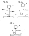
- FIG. 5a there is depicted a typical relationship between the laser sensor 42, the capillary tube 26 and the surface 22 of the depicted system 20 when the positional relationship (i.e. the distance) between the capillary tube 23 and the surface 22 is optimum for sample collecting purposes. More specifically, the surface 22 is situated generally in the X-Y plane, the capillary tube 23 is disposed immediately above the surface 22 and the laser sensor 42 is disposed on the side of the capillary tube 23 opposite the surface 22.
- the laser sensor 42 is fixed in relationship to the capillary tube 26.
- the Z-coordinate distance as measured between the laser sensor 42 and the capillary tube 23, indicated d SC/LS in Figs. 4a, 4b and 5a should be constant throughout a sample collecting operation even though the surface 22 may be raised or lowered (by way of the XYZ stage 28) during the operation. If it is therefore desired to determine the actual distance between the capillary tube 23 and the surface 22 once the distance between the laser sensor 42 and the capillary tube 23 (indicated d SC/LS in Figs.
- the distance between the capillary tube 23 and the surface 22 can be calculated by subtracting the thickness of the capillary tube 23 from the distance between the laser sensor 42 and the surface 22 (d POS/LS ).
- this laser source-to-surface distance is stored in the computer 30 and designated, for present purposes, as the target laser sensor-to-surface distance which is desired to be maintained throughout the sample collection process.
- the sampling process can be initiated by moving the surface 22 relative to the capillary tube 23 along the X-Y plane for the purpose of collecting samples from desired locations on, or along desired lanes across, the surface 22.
- the actual distance between the laser sensor 42 and the surface 22 is periodically measured with the distance-measuring means 40, and each measured actual laser sensor-to-surface distance is subsequently compared to the target laser sensor-to-surface distance, and adjustments are made, if necessary, to maintain the actual laser sensor-to-surface distance close to the target laser sensor-to-surface distance.
- the computer 30 i.e. the memory 30 thereof
- the computer 30 is preprogrammed with information relating to acceptable distance (i.e. tolerance) limits relative to the target distance.
- acceptable distance i.e. tolerance
- commands are sent to the XYZ stage 28 to initiate Z-axis adjustments between the capillary tube 23 and the surface 22 to bring the actual distance back in line with (i.e. within the tolerance limits of) the target laser source-to-surface distance.
- preset tolerance limits correspond to a predetermined range within which the actual laser source-to-surface distance can be close enough (e.g. within ⁇ 3 ⁇ m) to the desired target laser source-to-surface distance that no additional movement of the surface 22 toward or away from the capillary tube 23 is necessary.
- Figs. 5b and 5b there are depicted exemplary relationships between the laser sensor 42, the capillary tube 23 and the surface 22 when the capillary tube-to-surface distance is not optimum for sample collecting purposes.
- the capillary tube-to-surface distance in the component relationship depicted in the Fig. 5a view is taken to be optimum for sample collecting purposes, and accordingly the laser sensor-to-surface distance in this Fig 5a relationship is determined during the set-up phase of the sample collecting operations.
- the Fig. 5a the laser sensor-to-surface distance in this Fig 5a relationship is determined during the set-up phase of the sample collecting operations.
- the laser sensor-to-surface distance (d POS/LS ) is greater than the laser sensor-to-surface distance determined in the set-up phase - thus indicating that a wider-than-desired gap has developed between the capillary tube 23 and the surface 22. If the determined laser sensor-to-surface distance of the Fig. 5b example is outside of the pre-set tolerance limits, then the computer 30 will initiate appropriate commands to move (by way of the XYZ stage 28) the surface 22 toward the capillary tube 23 so that the actual laser sensor-to-surface distance moves closer to the target laser sensor-to-surface distance (e.g. the laser sensor-to-surface distance determined during the set-up phase of the operation).
- the laser sensor-to-surface distance (d POS/LS ) is less than the desired laser sensor-to-surface distance determined in the set-up phase - thus indicating that a smaller-than-desired gap has developed between the capillary tube 23 and the surface 22. In fact, such a determination could indicate that the capillary tube 23 has been bent upwardly by the surface 22. If the determined laser sensor-to-surface distance of the Fig. 5c example is outside the pre-set tolerance limits, then the computer 30 will initiate appropriate commands to move (by way of the XYZ stage 28) the surface away from the capillary tube 23 so that the actual laser sensor-to-surface distance moves closer to the target laser sensor-to-surface distance (i.e. the laser sensor-to-surface distance determined during the set-up phase of the operation).
- the control of the actual capillary tube-to-surface distance during a sample collecting process is comprised of a series of steps. Firstly and in preparation of a sample collection operation performed with the system 20, an operator adjusts the Z-axis position of the surface 22 until the surface 22 is positioned in relatively close proximity to the tip 26 of the capillary tube 23 so that the capillary tube tip-to-surface distance is optimum for sample collection purposes. During this set-up stage, the relative position between the surface 22 and the capillary tube tip 26 can be visually monitored by the operator who watches the images obtained through the webcam 48 and displayed upon the computer display screen 52. It will be understood, however, and as mentioned earlier, this initial set-up stage can be omitted in a fully automated operation.
- the operator enters appropriate commands into the computer 30 through the keyboard 31 thereof so that the initial (and actual) laser sensor-to-surface distance is determined with the distance-measuring means 40.
- distance-measuring means 40 (by way of the laser sensor 42) is used to measure the actual laser sensor-to-surface distance, and a signal which corresponds to the measured distance is conducted from the distance-measuring means 40 to the computer 30.
- This initial laser sensor-to-surface distance is stored within the computer memory 30 and designated, for present purposes, as the target laser sensor-to-surface distance to which subsequently-determined actual laser sensor-to-surface distances are ultimately compared.
- periodic measurements of the actual laser sensor-to-surface distances are taken with the distance-measuring means 40. Electrical signals corresponding to these measured distances are immediately transmitted to the computer 30 for comparison to the target laser sensor-to-surface distance.
- Such periodic measurements can be taken at preselected and regularly-spaced intervals of time (e.g. every one-half second), and the time interval between which these actual laser sensor-to-surface distances are taken can be preprogrammed into, or selected at, the computer 30.
- the samples collected from the surface 22 through the collection tube 23 are conducted to the mass spectrometer 32 and are analyzed thereat in a manner known in the art.
- a second control computer 34 (introduced earlier and shown in Fig. 1 ), having a display screen 38 and a keyboard 39, can be connected to the mass spectrometer 32 for controlling its operations.
- the keyboard 39 can be used for entering commands into the computer 34 and thereby controlling the operation and data collection of the mass spectrometer 32.
- the surface 22 is moved relative to the capillary tube 23 within the X-Y plane so that the tip 26 of the capillary tube 23 samples the surface 22 as the surface 22 sweeps beneath the probe 24.
- the computer 30 can be pre-programmed to either index the surface 22 within the X-Y plane so that alternative locations, or spots, can be positioned in sample-collecting registry with the capillary tube tip 26 for obtaining samples at the alternative locations or to move the surface 22 along an X or Y coordinate axis so that the surface 22 is sampled with the capillary tube 23 along a selected lane (such as the paths 18 of Fig. 3 ) across the surface 22.
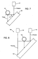
- FIG. 6a and 6b there is schematically illustrated the positional relationship between the surface 22 and the capillary tube tip 26 as the surface 22 is passed beneath the capillary tube tip 26 during a sample-collection operation and the movement of the capillary tube tip 26 during a re-optimization of the capillary tube-to-surface position.
- the surface 22 is depicted at an exaggerated angle with respect to the longitudinal axis of the capillary tube 23 for illustrative purposes.
- the surface 22 and the capillary tube 23 are moved relative to one another during a sample-collection process so that samples are collected from a lane of the surface 22 in the negative (-) X-coordinate direction indicated by the arrow 62, and within Fig. 6b , the surface 22 and the capillary tube 23 are moved relative to one another during a sample-collection process so that samples are collected from a lane of the surface 22 in the positive (+) X-coordinate direction indicated by the arrow 63.
- the dotted lines 64 and 66 depicted in Figs. 6a and 6b indicate the outer boundaries, or preset limits, between which the capillary tube tip 26 should be positioned in order that the optimum, or desired, distance is maintained between the surface 22 and the capillary tube tip 26 for sample collecting purposes.
- the capillary tube tip 26 should not be moved closer to the surface 22 (along the Z-axis) than is the line 64 nor should the capillary tube tip 26 be moved further from the surface 22 than is the line 66.
- the spaced-apart distance between the preset limits can be within a few microns, such as about 6 ⁇ m, from one another so that the preset limits (corresponding to the dotted lines 64 and 66) are each spaced at about 3 um from the target distance at which the surface 22 is optimally-arranged in relationship to the capillary tube tip 26. Accordingly and during a sample-collection operation performed with the system 20, actual laser sensor-to-surface distances are determined at spaced intervals of time, and appropriate signals which correspond to these actual laser sensor-to-surface distances are transmitted to the computer 30.
- Each measured actual laser sensor-to-surface distance is then compared, by means of appropriate software 70 ( Fig. 1 ) running in the computer 30, to the desired target distance between the laser sensor 42 and the surface 22, which target distance is bounded by the prescribed limit lines 64 and 66 (of Figs. 6a or 6b ). If the actual laser sensor-to-surface distance is determined to fall within the prescribed limit lines 64 and 66, no relative movement or adjustment of the surface 22 and the capillary tube tip 26 along the Z-axis is necessary.
- the Y-axis distance between the line of the beam emitted from the laser source 42 and the center of the capillary tube is about 500 ⁇ m.
- the angle i.e. the angle of tilt of the surface 22
- the product of tan( ) and 500 ⁇ m is only about 9 ⁇ m. This 9 ⁇ m value is an acceptable error and would not likely have a noticable effect on the signal levels sensed across the surface. If, in the event, that such an error is not acceptable, a system can employ two laser sensors to obtain a more accurate representation of the laser sensor-to-surface distance along the Z-axis distance.
- a fragment of a system including a surface 122, a capillary tube 123 and a pair of laser sensors 142 and 143 arranged above the capillary tube 123 so as to emit downwardly-directed beams equidistant from and on opposite sides of the capillary tube 123.
- An accurate calculation of the laser sensor-to-surface distance can be obtained by averaging the laser sensor-to-surface distances measured by the two laser sensors 142, 143. The value resulting from this calculation can be taken to be representative of the Z-axis distance between the capillary tube 123 and the surface 122 to reduce the likelihood of error resulting from a tilting of the surface 122 with respect to the X-Y plane.
- the system 20 automates the formulation of real-time re-optimization of the sample collection instrument-to-surface distance using distance measurements obtained with a laser sensor 42.
- the distance measurement analysis includes the periodic measurement of the actual distance between the laser sensor 42 and the surface 22 followed by a comparison of each of the measured actual laser sensor-to-surface distances to a target laser sensor-to-surface distance.
- the system 20 can automatically and continuously re-optimize the capillary tube-to-surface distance during the sample collection procedure by adjusting the spaced laser sensor-to-surface distance, as necessary, along the Z-coordinate axis.
- the surface 22 can be moved along the X-Y plane (and relative to the capillary tube 23) to accommodate the automatic collection of samples with the capillary tube 23 along multiple parallel lanes upon the surface 22 with equal or customized spacing between the lanes. Samples can be collected with the aforedescribed system 20 at constant scan speeds or at customized, or varying, scan speeds.
- the principle advantages provided by the system 20 and associated method for controlling the capillary tube-to-surface distance throughout a sample-collection process relate to the obviation of any need for operation intervention and manual control of the capillary tube-to-surface distance (i.e. along the Z-coordinate axis) during a sample-collection process. Accordingly, the precision of a sample-collection operation conducted with the system 20 will not be limited by the skill of an operator required to monitor the sample-collection process. Moreover, the system 20 also provides advantages which bear directly upon the accuracy of samples collected with the capillary tube 23.
- the aforedescribed system 20 and process provide a further advantage in sample collecting equipment which employs componentry, such as the emitter 25 having a spray tip, which are intended to be positioned in a desired spatial relationship, or assignment, with one another.
- componentry such as the emitter 25 having a spray tip
- a change in the spray tip-to-surface distance also results in a change in the sampling capillary-to-surface distance by a corresponding amount.
- the system 20 and process of the present invention helps to maintain a desired capillary tube-to-surface distance during a sample collecting process, the system 20 and process also help to maintain desired spatial relationship between the emitter, the collection tube and the surface to be sampled.
Landscapes
- Chemical & Material Sciences (AREA)
- Analytical Chemistry (AREA)
- Length Measuring Devices By Optical Means (AREA)
- Sampling And Sample Adjustment (AREA)
- Electron Tubes For Measurement (AREA)
Applications Claiming Priority (2)
| Application Number | Priority Date | Filing Date | Title |
|---|---|---|---|
| US12/217,225 US8117929B2 (en) | 2008-07-02 | 2008-07-02 | Control of the positional relationship between a sample collection instrument and a surface to be analyzed during a sampling procedure using a laser sensor |
| PCT/US2009/003347 WO2010002427A2 (en) | 2008-07-02 | 2009-06-02 | Control of the positional relationship between a sample collection instrument and a surface to be analyzed during a sampling procedure using a laser sensor |
Publications (2)
| Publication Number | Publication Date |
|---|---|
| EP2304766A2 EP2304766A2 (en) | 2011-04-06 |
| EP2304766B1 true EP2304766B1 (en) | 2019-07-31 |
Family
ID=41327314
Family Applications (1)
| Application Number | Title | Priority Date | Filing Date |
|---|---|---|---|
| EP09773880.1A Active EP2304766B1 (en) | 2008-07-02 | 2009-06-02 | Control of the positional relationship between a sample collection instrument and a surface to be analyzed during a sampling procedure using a laser sensor |
Country Status (5)
| Country | Link |
|---|---|
| US (1) | US8117929B2 (enExample) |
| EP (1) | EP2304766B1 (enExample) |
| JP (1) | JP5710473B2 (enExample) |
| CA (1) | CA2729701C (enExample) |
| WO (1) | WO2010002427A2 (enExample) |
Families Citing this family (11)
| Publication number | Priority date | Publication date | Assignee | Title |
|---|---|---|---|---|
| US8766177B2 (en) | 2010-10-11 | 2014-07-01 | University Of North Texas | Nanomanipulation coupled nanospray mass spectrometry (NMS) |
| JP2012237557A (ja) * | 2011-05-09 | 2012-12-06 | Shimadzu Corp | 液体試料採取装置及び液体試料採取方法 |
| US9176028B2 (en) | 2012-10-04 | 2015-11-03 | Ut-Battelle, Llc | Ball assisted device for analytical surface sampling |
| US10060838B2 (en) | 2015-04-09 | 2018-08-28 | Ut-Battelle, Llc | Capture probe |
| US9632066B2 (en) | 2015-04-09 | 2017-04-25 | Ut-Battelle, Llc | Open port sampling interface |
| WO2017181394A1 (zh) * | 2016-04-21 | 2017-10-26 | 深圳市樊溪电子有限公司 | 一种油气包裹体成分取样方法 |
| US11125657B2 (en) | 2018-01-30 | 2021-09-21 | Ut-Battelle, Llc | Sampling probe |
| US20220208538A1 (en) * | 2019-05-31 | 2022-06-30 | Purdue Research Foundation | Integrated microfluidic probe (imfp) and methods of use thereof |
| DE102021128848B4 (de) * | 2021-11-05 | 2025-08-07 | Bruker Daltonics GmbH & Co. KG | Vorrichtung zum desorbierenden Abtasten von Analytmaterial auf einem Probenträger |
| CN116218649B (zh) * | 2022-12-30 | 2024-07-02 | 德诺杰亿(北京)生物科技有限公司 | 基因分析仪上样台的自动校准方法、装置及基因分析仪 |
| CN118857839B (zh) * | 2024-09-25 | 2024-12-06 | 大连馨士俐科技服务有限公司 | 一种用于市政道路施工质量检测的取芯装置 |
Family Cites Families (12)
| Publication number | Priority date | Publication date | Assignee | Title |
|---|---|---|---|---|
| JPH0687003B2 (ja) * | 1990-02-09 | 1994-11-02 | 株式会社日立製作所 | 走査型トンネル顕微鏡付き走査型電子顕微鏡 |
| JPH04162337A (ja) * | 1990-10-24 | 1992-06-05 | Hitachi Ltd | 電子線装置 |
| DE4116803A1 (de) * | 1991-05-23 | 1992-12-10 | Agfa Gevaert Ag | Vorrichtung zur gleichmaessigen ausleuchtung einer projektionsflaeche |
| US5196713A (en) * | 1991-08-22 | 1993-03-23 | Wyko Corporation | Optical position sensor with corner-cube and servo-feedback for scanning microscopes |
| JP3015980B2 (ja) * | 1992-01-10 | 2000-03-06 | キヤノン株式会社 | 原子間力顕微鏡及び記録再生装置及び再生装置 |
| JP2002175770A (ja) * | 2000-12-08 | 2002-06-21 | Hitachi Ltd | 気体排気用試料室及びそれを用いた回路パターン形成装置 |
| GB0112903D0 (en) * | 2001-05-26 | 2001-07-18 | Univ Heriot Watt | Permeability measurement apparatus and method |
| US6803566B2 (en) * | 2002-04-16 | 2004-10-12 | Ut-Battelle, Llc | Sampling probe for microarray read out using electrospray mass spectrometry |
| JP4427824B2 (ja) * | 2003-09-03 | 2010-03-10 | 日立建機株式会社 | プローブの製造方法、プローブおよび走査型プローブ顕微鏡 |
| US20080033275A1 (en) * | 2004-04-28 | 2008-02-07 | Blank Thomas B | Method and Apparatus for Sample Probe Movement Control |
| JP2006215004A (ja) * | 2005-02-07 | 2006-08-17 | Ricoh Co Ltd | 近接場光顕微鏡、近接場光による試料測定方法 |
| US7295026B2 (en) * | 2005-06-03 | 2007-11-13 | Ut-Battelle, Llc | Automated position control of a surface array relative to a liquid microjunction surface sampler |
-
2008
- 2008-07-02 US US12/217,225 patent/US8117929B2/en active Active
-
2009
- 2009-06-02 WO PCT/US2009/003347 patent/WO2010002427A2/en not_active Ceased
- 2009-06-02 CA CA2729701A patent/CA2729701C/en active Active
- 2009-06-02 JP JP2011516271A patent/JP5710473B2/ja active Active
- 2009-06-02 EP EP09773880.1A patent/EP2304766B1/en active Active
Non-Patent Citations (1)
| Title |
|---|
| VILMOS KERTESZ ET AL: "Scanning and Surface Alignment Considerations in Chemical Imaging with Desorption Electrospray Mass Spectrometry", ANALYTICAL CHEMISTRY, vol. 80, no. 4, 1 February 2008 (2008-02-01), US, pages 1027 - 1032, XP055497376, ISSN: 0003-2700, DOI: 10.1021/ac701947d * |
Also Published As
| Publication number | Publication date |
|---|---|
| EP2304766A2 (en) | 2011-04-06 |
| CA2729701A1 (en) | 2010-01-07 |
| US20100000338A1 (en) | 2010-01-07 |
| WO2010002427A3 (en) | 2010-02-25 |
| CA2729701C (en) | 2015-11-03 |
| JP2011527075A (ja) | 2011-10-20 |
| JP5710473B2 (ja) | 2015-04-30 |
| US8117929B2 (en) | 2012-02-21 |
| WO2010002427A2 (en) | 2010-01-07 |
Similar Documents
| Publication | Publication Date | Title |
|---|---|---|
| EP2304766B1 (en) | Control of the positional relationship between a sample collection instrument and a surface to be analyzed during a sampling procedure using a laser sensor | |
| US7995216B2 (en) | Control of the positional relationship between a sample collection instrument and a surface to be analyzed during a sampling procedure with image analysis | |
| US5920068A (en) | Analysis of semiconductor surfaces by secondary ion mass spectrometry | |
| CA2754363C (en) | Method of and system for formation and withdrawal of a sample from a surface to be analyzed | |
| EP1894225B1 (en) | Automated position control of a surface array relative to a liquid microjunction surface sampler | |
| US8530851B2 (en) | Electron beam profile measurement system and method with optional Faraday cup | |
| US8058610B2 (en) | Mass spectrometer | |
| US11707847B2 (en) | Position detector and method for 3D position determination | |
| WO2017033591A1 (ja) | 荷電粒子線装置および試料ステージのアライメント調整方法 | |
| US8067752B2 (en) | Semiconductor testing method and semiconductor tester | |
| US12368037B2 (en) | Device for desorption scanning of analyte material on a sample support | |
| US12461126B2 (en) | Probe device | |
| US20030081216A1 (en) | Graphical user interface for sample positioning | |
| Piotrowski et al. | A Method for Defining the Position of Ion Formation in a MALDI TOFMS by Analysis of the Laser Image on the Sample Surface |
Legal Events
| Date | Code | Title | Description |
|---|---|---|---|
| PUAI | Public reference made under article 153(3) epc to a published international application that has entered the european phase |
Free format text: ORIGINAL CODE: 0009012 |
|
| 17P | Request for examination filed |
Effective date: 20110107 |
|
| AK | Designated contracting states |
Kind code of ref document: A2 Designated state(s): AT BE BG CH CY CZ DE DK EE ES FI FR GB GR HR HU IE IS IT LI LT LU LV MC MK MT NL NO PL PT RO SE SI SK TR |
|
| AX | Request for extension of the european patent |
Extension state: AL BA RS |
|
| RIN1 | Information on inventor provided before grant (corrected) |
Inventor name: VAN BERKEL, GARY, L. Inventor name: KERTESZ, VILMOS |
|
| DAX | Request for extension of the european patent (deleted) | ||
| 17Q | First examination report despatched |
Effective date: 20140624 |
|
| STAA | Information on the status of an ep patent application or granted ep patent |
Free format text: STATUS: EXAMINATION IS IN PROGRESS |
|
| GRAP | Despatch of communication of intention to grant a patent |
Free format text: ORIGINAL CODE: EPIDOSNIGR1 |
|
| STAA | Information on the status of an ep patent application or granted ep patent |
Free format text: STATUS: GRANT OF PATENT IS INTENDED |
|
| INTG | Intention to grant announced |
Effective date: 20180928 |
|
| GRAS | Grant fee paid |
Free format text: ORIGINAL CODE: EPIDOSNIGR3 |
|
| GRAA | (expected) grant |
Free format text: ORIGINAL CODE: 0009210 |
|
| STAA | Information on the status of an ep patent application or granted ep patent |
Free format text: STATUS: THE PATENT HAS BEEN GRANTED |
|
| AK | Designated contracting states |
Kind code of ref document: B1 Designated state(s): AT BE BG CH CY CZ DE DK EE ES FI FR GB GR HR HU IE IS IT LI LT LU LV MC MK MT NL NO PL PT RO SE SI SK TR |
|
| REG | Reference to a national code |
Ref country code: CH Ref legal event code: EP Ref country code: GB Ref legal event code: FG4D |
|
| REG | Reference to a national code |
Ref country code: AT Ref legal event code: REF Ref document number: 1161820 Country of ref document: AT Kind code of ref document: T Effective date: 20190815 |
|
| REG | Reference to a national code |
Ref country code: IE Ref legal event code: FG4D |
|
| REG | Reference to a national code |
Ref country code: DE Ref legal event code: R096 Ref document number: 602009059304 Country of ref document: DE |
|
| REG | Reference to a national code |
Ref country code: NL Ref legal event code: MP Effective date: 20190731 |
|
| REG | Reference to a national code |
Ref country code: LT Ref legal event code: MG4D |
|
| REG | Reference to a national code |
Ref country code: AT Ref legal event code: MK05 Ref document number: 1161820 Country of ref document: AT Kind code of ref document: T Effective date: 20190731 |
|
| PG25 | Lapsed in a contracting state [announced via postgrant information from national office to epo] |
Ref country code: PT Free format text: LAPSE BECAUSE OF FAILURE TO SUBMIT A TRANSLATION OF THE DESCRIPTION OR TO PAY THE FEE WITHIN THE PRESCRIBED TIME-LIMIT Effective date: 20191202 Ref country code: SE Free format text: LAPSE BECAUSE OF FAILURE TO SUBMIT A TRANSLATION OF THE DESCRIPTION OR TO PAY THE FEE WITHIN THE PRESCRIBED TIME-LIMIT Effective date: 20190731 Ref country code: AT Free format text: LAPSE BECAUSE OF FAILURE TO SUBMIT A TRANSLATION OF THE DESCRIPTION OR TO PAY THE FEE WITHIN THE PRESCRIBED TIME-LIMIT Effective date: 20190731 Ref country code: NO Free format text: LAPSE BECAUSE OF FAILURE TO SUBMIT A TRANSLATION OF THE DESCRIPTION OR TO PAY THE FEE WITHIN THE PRESCRIBED TIME-LIMIT Effective date: 20191031 Ref country code: FI Free format text: LAPSE BECAUSE OF FAILURE TO SUBMIT A TRANSLATION OF THE DESCRIPTION OR TO PAY THE FEE WITHIN THE PRESCRIBED TIME-LIMIT Effective date: 20190731 Ref country code: NL Free format text: LAPSE BECAUSE OF FAILURE TO SUBMIT A TRANSLATION OF THE DESCRIPTION OR TO PAY THE FEE WITHIN THE PRESCRIBED TIME-LIMIT Effective date: 20190731 Ref country code: BG Free format text: LAPSE BECAUSE OF FAILURE TO SUBMIT A TRANSLATION OF THE DESCRIPTION OR TO PAY THE FEE WITHIN THE PRESCRIBED TIME-LIMIT Effective date: 20191031 Ref country code: HR Free format text: LAPSE BECAUSE OF FAILURE TO SUBMIT A TRANSLATION OF THE DESCRIPTION OR TO PAY THE FEE WITHIN THE PRESCRIBED TIME-LIMIT Effective date: 20190731 Ref country code: LT Free format text: LAPSE BECAUSE OF FAILURE TO SUBMIT A TRANSLATION OF THE DESCRIPTION OR TO PAY THE FEE WITHIN THE PRESCRIBED TIME-LIMIT Effective date: 20190731 |
|
| PG25 | Lapsed in a contracting state [announced via postgrant information from national office to epo] |
Ref country code: GR Free format text: LAPSE BECAUSE OF FAILURE TO SUBMIT A TRANSLATION OF THE DESCRIPTION OR TO PAY THE FEE WITHIN THE PRESCRIBED TIME-LIMIT Effective date: 20191101 Ref country code: ES Free format text: LAPSE BECAUSE OF FAILURE TO SUBMIT A TRANSLATION OF THE DESCRIPTION OR TO PAY THE FEE WITHIN THE PRESCRIBED TIME-LIMIT Effective date: 20190731 Ref country code: LV Free format text: LAPSE BECAUSE OF FAILURE TO SUBMIT A TRANSLATION OF THE DESCRIPTION OR TO PAY THE FEE WITHIN THE PRESCRIBED TIME-LIMIT Effective date: 20190731 Ref country code: IS Free format text: LAPSE BECAUSE OF FAILURE TO SUBMIT A TRANSLATION OF THE DESCRIPTION OR TO PAY THE FEE WITHIN THE PRESCRIBED TIME-LIMIT Effective date: 20191130 |
|
| PG25 | Lapsed in a contracting state [announced via postgrant information from national office to epo] |
Ref country code: TR Free format text: LAPSE BECAUSE OF FAILURE TO SUBMIT A TRANSLATION OF THE DESCRIPTION OR TO PAY THE FEE WITHIN THE PRESCRIBED TIME-LIMIT Effective date: 20190731 |
|
| PG25 | Lapsed in a contracting state [announced via postgrant information from national office to epo] |
Ref country code: PL Free format text: LAPSE BECAUSE OF FAILURE TO SUBMIT A TRANSLATION OF THE DESCRIPTION OR TO PAY THE FEE WITHIN THE PRESCRIBED TIME-LIMIT Effective date: 20190731 Ref country code: DK Free format text: LAPSE BECAUSE OF FAILURE TO SUBMIT A TRANSLATION OF THE DESCRIPTION OR TO PAY THE FEE WITHIN THE PRESCRIBED TIME-LIMIT Effective date: 20190731 Ref country code: RO Free format text: LAPSE BECAUSE OF FAILURE TO SUBMIT A TRANSLATION OF THE DESCRIPTION OR TO PAY THE FEE WITHIN THE PRESCRIBED TIME-LIMIT Effective date: 20190731 Ref country code: IT Free format text: LAPSE BECAUSE OF FAILURE TO SUBMIT A TRANSLATION OF THE DESCRIPTION OR TO PAY THE FEE WITHIN THE PRESCRIBED TIME-LIMIT Effective date: 20190731 Ref country code: EE Free format text: LAPSE BECAUSE OF FAILURE TO SUBMIT A TRANSLATION OF THE DESCRIPTION OR TO PAY THE FEE WITHIN THE PRESCRIBED TIME-LIMIT Effective date: 20190731 |
|
| PG25 | Lapsed in a contracting state [announced via postgrant information from national office to epo] |
Ref country code: IS Free format text: LAPSE BECAUSE OF FAILURE TO SUBMIT A TRANSLATION OF THE DESCRIPTION OR TO PAY THE FEE WITHIN THE PRESCRIBED TIME-LIMIT Effective date: 20200224 Ref country code: CZ Free format text: LAPSE BECAUSE OF FAILURE TO SUBMIT A TRANSLATION OF THE DESCRIPTION OR TO PAY THE FEE WITHIN THE PRESCRIBED TIME-LIMIT Effective date: 20190731 Ref country code: SK Free format text: LAPSE BECAUSE OF FAILURE TO SUBMIT A TRANSLATION OF THE DESCRIPTION OR TO PAY THE FEE WITHIN THE PRESCRIBED TIME-LIMIT Effective date: 20190731 |
|
| REG | Reference to a national code |
Ref country code: DE Ref legal event code: R097 Ref document number: 602009059304 Country of ref document: DE |
|
| PLBE | No opposition filed within time limit |
Free format text: ORIGINAL CODE: 0009261 |
|
| STAA | Information on the status of an ep patent application or granted ep patent |
Free format text: STATUS: NO OPPOSITION FILED WITHIN TIME LIMIT |
|
| PG2D | Information on lapse in contracting state deleted |
Ref country code: IS |
|
| PG25 | Lapsed in a contracting state [announced via postgrant information from national office to epo] |
Ref country code: IS Free format text: LAPSE BECAUSE OF FAILURE TO SUBMIT A TRANSLATION OF THE DESCRIPTION OR TO PAY THE FEE WITHIN THE PRESCRIBED TIME-LIMIT Effective date: 20191030 |
|
| 26N | No opposition filed |
Effective date: 20200603 |
|
| PG25 | Lapsed in a contracting state [announced via postgrant information from national office to epo] |
Ref country code: SI Free format text: LAPSE BECAUSE OF FAILURE TO SUBMIT A TRANSLATION OF THE DESCRIPTION OR TO PAY THE FEE WITHIN THE PRESCRIBED TIME-LIMIT Effective date: 20190731 |
|
| PG25 | Lapsed in a contracting state [announced via postgrant information from national office to epo] |
Ref country code: MC Free format text: LAPSE BECAUSE OF FAILURE TO SUBMIT A TRANSLATION OF THE DESCRIPTION OR TO PAY THE FEE WITHIN THE PRESCRIBED TIME-LIMIT Effective date: 20190731 |
|
| REG | Reference to a national code |
Ref country code: CH Ref legal event code: PL |
|
| PG25 | Lapsed in a contracting state [announced via postgrant information from national office to epo] |
Ref country code: LU Free format text: LAPSE BECAUSE OF NON-PAYMENT OF DUE FEES Effective date: 20200602 |
|
| REG | Reference to a national code |
Ref country code: BE Ref legal event code: MM Effective date: 20200630 |
|
| PG25 | Lapsed in a contracting state [announced via postgrant information from national office to epo] |
Ref country code: CH Free format text: LAPSE BECAUSE OF NON-PAYMENT OF DUE FEES Effective date: 20200630 Ref country code: LI Free format text: LAPSE BECAUSE OF NON-PAYMENT OF DUE FEES Effective date: 20200630 Ref country code: IE Free format text: LAPSE BECAUSE OF NON-PAYMENT OF DUE FEES Effective date: 20200602 |
|
| PG25 | Lapsed in a contracting state [announced via postgrant information from national office to epo] |
Ref country code: BE Free format text: LAPSE BECAUSE OF NON-PAYMENT OF DUE FEES Effective date: 20200630 |
|
| PG25 | Lapsed in a contracting state [announced via postgrant information from national office to epo] |
Ref country code: MT Free format text: LAPSE BECAUSE OF FAILURE TO SUBMIT A TRANSLATION OF THE DESCRIPTION OR TO PAY THE FEE WITHIN THE PRESCRIBED TIME-LIMIT Effective date: 20190731 Ref country code: CY Free format text: LAPSE BECAUSE OF FAILURE TO SUBMIT A TRANSLATION OF THE DESCRIPTION OR TO PAY THE FEE WITHIN THE PRESCRIBED TIME-LIMIT Effective date: 20190731 |
|
| PG25 | Lapsed in a contracting state [announced via postgrant information from national office to epo] |
Ref country code: MK Free format text: LAPSE BECAUSE OF FAILURE TO SUBMIT A TRANSLATION OF THE DESCRIPTION OR TO PAY THE FEE WITHIN THE PRESCRIBED TIME-LIMIT Effective date: 20190731 |
|
| P01 | Opt-out of the competence of the unified patent court (upc) registered |
Effective date: 20230606 |
|
| PGFP | Annual fee paid to national office [announced via postgrant information from national office to epo] |
Ref country code: DE Payment date: 20250520 Year of fee payment: 17 |
|
| PGFP | Annual fee paid to national office [announced via postgrant information from national office to epo] |
Ref country code: GB Payment date: 20250520 Year of fee payment: 17 |
|
| PGFP | Annual fee paid to national office [announced via postgrant information from national office to epo] |
Ref country code: FR Payment date: 20250520 Year of fee payment: 17 |