EP2304261B2 - Procédé de réalisation d'un étrier de frein - Google Patents
Procédé de réalisation d'un étrier de frein Download PDFInfo
- Publication number
- EP2304261B2 EP2304261B2 EP09777399.8A EP09777399A EP2304261B2 EP 2304261 B2 EP2304261 B2 EP 2304261B2 EP 09777399 A EP09777399 A EP 09777399A EP 2304261 B2 EP2304261 B2 EP 2304261B2
- Authority
- EP
- European Patent Office
- Prior art keywords
- calliper
- recess
- machining tool
- section
- supporting face
- Prior art date
- Legal status (The legal status is an assumption and is not a legal conclusion. Google has not performed a legal analysis and makes no representation as to the accuracy of the status listed.)
- Active
Links
- 238000004519 manufacturing process Methods 0.000 title claims description 8
- 238000003754 machining Methods 0.000 claims description 21
- 238000000034 method Methods 0.000 claims description 12
- 238000012545 processing Methods 0.000 description 26
- 238000013461 design Methods 0.000 description 4
- 238000003801 milling Methods 0.000 description 3
- 230000015572 biosynthetic process Effects 0.000 description 2
- 238000007639 printing Methods 0.000 description 2
- 238000013459 approach Methods 0.000 description 1
- 230000000295 complement effect Effects 0.000 description 1
- 230000008878 coupling Effects 0.000 description 1
- 238000010168 coupling process Methods 0.000 description 1
- 238000005859 coupling reaction Methods 0.000 description 1
- 230000001419 dependent effect Effects 0.000 description 1
- 238000003780 insertion Methods 0.000 description 1
- 230000037431 insertion Effects 0.000 description 1
- 238000007789 sealing Methods 0.000 description 1
- 230000003313 weakening effect Effects 0.000 description 1
Images


Classifications
-
- B—PERFORMING OPERATIONS; TRANSPORTING
- B23—MACHINE TOOLS; METAL-WORKING NOT OTHERWISE PROVIDED FOR
- B23C—MILLING
- B23C3/00—Milling particular work; Special milling operations; Machines therefor
-
- F—MECHANICAL ENGINEERING; LIGHTING; HEATING; WEAPONS; BLASTING
- F16—ENGINEERING ELEMENTS AND UNITS; GENERAL MEASURES FOR PRODUCING AND MAINTAINING EFFECTIVE FUNCTIONING OF MACHINES OR INSTALLATIONS; THERMAL INSULATION IN GENERAL
- F16D—COUPLINGS FOR TRANSMITTING ROTATION; CLUTCHES; BRAKES
- F16D55/00—Brakes with substantially-radial braking surfaces pressed together in axial direction, e.g. disc brakes
- F16D55/02—Brakes with substantially-radial braking surfaces pressed together in axial direction, e.g. disc brakes with axially-movable discs or pads pressed against axially-located rotating members
- F16D55/22—Brakes with substantially-radial braking surfaces pressed together in axial direction, e.g. disc brakes with axially-movable discs or pads pressed against axially-located rotating members by clamping an axially-located rotating disc between movable braking members, e.g. movable brake discs or brake pads
-
- F—MECHANICAL ENGINEERING; LIGHTING; HEATING; WEAPONS; BLASTING
- F16—ENGINEERING ELEMENTS AND UNITS; GENERAL MEASURES FOR PRODUCING AND MAINTAINING EFFECTIVE FUNCTIONING OF MACHINES OR INSTALLATIONS; THERMAL INSULATION IN GENERAL
- F16D—COUPLINGS FOR TRANSMITTING ROTATION; CLUTCHES; BRAKES
- F16D55/00—Brakes with substantially-radial braking surfaces pressed together in axial direction, e.g. disc brakes
- F16D2055/0004—Parts or details of disc brakes
- F16D2055/0016—Brake calipers
-
- F—MECHANICAL ENGINEERING; LIGHTING; HEATING; WEAPONS; BLASTING
- F16—ENGINEERING ELEMENTS AND UNITS; GENERAL MEASURES FOR PRODUCING AND MAINTAINING EFFECTIVE FUNCTIONING OF MACHINES OR INSTALLATIONS; THERMAL INSULATION IN GENERAL
- F16D—COUPLINGS FOR TRANSMITTING ROTATION; CLUTCHES; BRAKES
- F16D2125/00—Components of actuators
- F16D2125/18—Mechanical mechanisms
- F16D2125/20—Mechanical mechanisms converting rotation to linear movement or vice versa
- F16D2125/22—Mechanical mechanisms converting rotation to linear movement or vice versa acting transversely to the axis of rotation
- F16D2125/28—Cams; Levers with cams
- F16D2125/32—Cams; Levers with cams acting on one cam follower
-
- F—MECHANICAL ENGINEERING; LIGHTING; HEATING; WEAPONS; BLASTING
- F16—ENGINEERING ELEMENTS AND UNITS; GENERAL MEASURES FOR PRODUCING AND MAINTAINING EFFECTIVE FUNCTIONING OF MACHINES OR INSTALLATIONS; THERMAL INSULATION IN GENERAL
- F16D—COUPLINGS FOR TRANSMITTING ROTATION; CLUTCHES; BRAKES
- F16D2250/00—Manufacturing; Assembly
- F16D2250/0092—Tools or machines for producing linings
-
- Y—GENERAL TAGGING OF NEW TECHNOLOGICAL DEVELOPMENTS; GENERAL TAGGING OF CROSS-SECTIONAL TECHNOLOGIES SPANNING OVER SEVERAL SECTIONS OF THE IPC; TECHNICAL SUBJECTS COVERED BY FORMER USPC CROSS-REFERENCE ART COLLECTIONS [XRACs] AND DIGESTS
- Y10—TECHNICAL SUBJECTS COVERED BY FORMER USPC
- Y10T—TECHNICAL SUBJECTS COVERED BY FORMER US CLASSIFICATION
- Y10T29/00—Metal working
- Y10T29/49—Method of mechanical manufacture
- Y10T29/49995—Shaping one-piece blank by removing material
Definitions
- the invention relates to a method for producing a caliper disc brake, particularly for commercial vehicles.
- a method of the type mentioned above is known, for example from DE 195 15 063 C2 .
- a processing tool for forming the support surface is inserted into the interior of the saddle through a specially designed working opening.
- Comparable manufacturing processes are known from EP 1 881 472 A1 , from the DE 10 2005 054 402 B4 as well as from the DE 10 2007 001 960 A1 , which discloses a method according to the preamble of claims 1 and 2, and which relates to the same brake as that DE 10 2007 041 658 A1 .
- Forming the working opening for inserting the machining tool results in a weakening of the brake caliper.
- additional measures are required to close the work opening after processing, and the closure must also be tight.
- the JP2004-353850 A1 shows the formation of an axial groove to secure rotation using a milling cutter.
- the invention relates to a brake with a one-piece, closed caliper, the interior of which is very difficult to access.
- the invention is based on the object of the manufacturing process according to the DE 195 15 063 C2 to be further developed in such a way that the effort is reduced, the saddle is not weakened and no additional connecting elements are required, which are exposed to heavy loads during operation.
- the object is achieved by the manufacturing method according to claim 1 or claim 2.
- the invention is based on the knowledge that when using the recess into which the brake disc protrudes when installed in order to introduce the processing tool to form the support surface, an additional working opening is not required, even with a one-piece saddle, and the support surface is not outside either of the saddle must be trained.
- the processing tool can also be inserted into the caliper interior through the assembly/disassembly opening for the brake pad in order to form the support surface.
- the support surface is at least partially flat.
- the support surface has the shape of a channel, at least in sections.
- the channel has an arcuate, in particular a circular arc-shaped, contour.
- the design of the support surface depends on the other conditions in the brake, in particular on the application device which is usually arranged inside the caliper.
- the processing tool has an L-shaped holder and can be moved into a working position translationally and rotationally about an axis in the direction of the longitudinal extension of one of the legs of the "L" with respect to the saddle.
- the saddle can also carry out complementary movements with respect to the tool.
- the invention covers also solutions in which both the processing tool and the saddle are moved or adjusted. This also applies to the movements/adjustments described below.
- the leg of the "L” is moved with the processing tool into the first or second recess, with its longitudinal axis parallel to the main plane of a brake disc which projects into the first recess when installed, in a second step, the holder is rotated about an axis in the direction of the longitudinal extent of the other leg of the "L", so that the processing tool faces the saddle section on the clamping side, in a third step, the processing tool is moved towards the saddle section on the clamping side and in a fourth step the support surface is formed.
- the machining tool is first introduced with a lateral orientation into the first or second recess and thus into the saddle interior and only then is it rotated into an orientation suitable for machining the support surface and brought towards the support surface to be formed.
- This takes into account the difficulty that the "width" of the first and second recesses is generally smaller than the "length" of the leg of the "L” with the processing tool.
- the problem that the length of the leg of the "L” with the machining tool is greater than the width of the first and second recess is solved in that the machining tool is pushed "obliquely" through the first or second recess into the interior of the Saddle is introduced.
- the angle of attack can be 30° to 80°, preferably 40° to 70°, more preferably 50° to 60°.
- the method according to the invention also covers a version in which the application-side caliper section has at least one guide surface for holding and/or guiding a brake pad, a pressure piece, at least one pressure spindle device and/or at least one pressure stamp device in radial and/or circumferential directions of the brake, wherein It is provided that, to form the guide surface, a processing tool is moved through the first or second recess into the area in which the guide surface is to be formed.
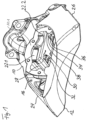
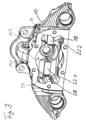
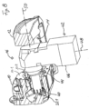
- the brake caliper shown has a caliper section 10 on the application side and a caliper section 12 on the rim side.
- the rim-side saddle section is (largely) closed, which contributes to the stable design.
- a brake disc projects into the first recess 14, so that part of the brake disc lies between the two caliper sections 10 and 12.
- the second recess 16 is used to mount/remove brake pads (also not shown in the drawing).
- a clamping shaft 18.1, 18.2 arranged inside the brake caliper 10, 12 is shown, which is located via bearings 20.1, 20.2 on support surfaces 22.1, 22.2 (cf. Figures 1 and 3 ) is supported, and when pivoting in the direction of rotation D, clamping parts mounted in front of it, such as a brake pad, press against the brake disc.
- the clamping shaft 18.1, 18.2 with a rotary lever 18.3 is part of a clamping device arranged in the brake caliper 10, 12, but not shown in detail, as used in commercial vehicle disc brakes. In this version, the rotary lever 18.3 is also preferably located inside the brake caliper 10, 12.
- the two saddle sections 10 and 12 are formed in one piece with each other. They are connected to one another via webs 24, 26, which, when installed, extend over the brake disc.
- Guide surfaces 28, 30, 32, 34, 36, 37, 38, 39 are provided for holding and / or guiding a pressure piece and / or the brake pad on the application side in the radial or circumferential direction of the brake disc.
- further guide surfaces can also be formed which serve additional purposes, namely, for example, holding and/or guiding a printing spindle device and/or a printing stamp device.
- the axial opening 10.2 also serves to later introduce the previously mentioned parts of the clamping device.
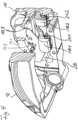
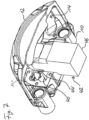
- a machining tool 40 in the form of an end mill with an L-shaped holder 42 is inserted from radially inside through the first recess 14 into the saddle interior.
- One leg 44 of the "L”, which carries the processing tool 40, is parallel to a main plane of the brake disc in the installed state. Insertion into the first recess is possible in this position because the leg 44 of the "L” is shorter than the length of the first recess. In a position rotated 90°, the leg 44 would not enter the first recess 14 fit because its length is greater than the width of the first recess 14.
- the guide surfaces 22.1 and 22.2 are flat.
- the support surfaces mentioned can also be designed in the manner of a channel with a circular arc-shaped contour.
- the processing tool 40 is moved out of the interior of the saddle again. The movements described above take place in the reverse order.
- the longitudinal axis of the leg 44 is designated by the reference number 50, cf. Figure 8 .
- the processing tool 40 with the L-shaped holder 42 is inserted into the first recess 14 in a position in which the longitudinal axis 50 of the leg 44 with the processing tool 40 is oblique with respect to the main plane 52 of the brake disc (not shown). is employed.
- the angle of attack ⁇ is approximately 55°, cf. Figure 9 (a) .
- the tool 40 is then moved translationally into the interior of the saddle. This is then done in accordance with Figure 9 (c) a pivoting of the holder 42 with the processing tool 40 with respect to the saddle about an axis perpendicular to the two longitudinal axes 48 and 50.
- the holder 42 can be pivoted with the processing tool 40 with respect to the saddle.
- the saddle can also be pivoted with respect to the aforementioned elements. Both can also be pivoted at the same time.
- Figure 9 (d) shows a state in which compared to the Figure 9 (c) has been pivoted even further.
- Figure 9 (f) shows the working position in which the support surfaces 22.1 and 22.2 are formed with the processing tool 40.
- the holder 42 with the processing tool 40 is moved out in the reverse order to the move in.
Landscapes
- Engineering & Computer Science (AREA)
- Mechanical Engineering (AREA)
- General Engineering & Computer Science (AREA)
- Braking Arrangements (AREA)
Claims (9)
- Procédé de réalisation d'un étrier d'un frein à disque à étrier, en particulier pour des véhicules utilitaires, dans lequel l'étrier présente :une partie d'étrier (10) du côté d'application du frein, avec au moins une face d'appui (22.1, 22.2) pour absorber des forces de serrage lors du freinage, une partie d'étrier (12) du côté de la jante, réalisée d'un seul tenant avec la partie d'étrier du côté d'application du frein, et un premier évidement (14) situé entre les deux parties d'étrier, dans lequel à l'état monté au moins un disque de frein fait saillie au moins partiellement, caractérisé en ce quepour la réalisation de la face d'appui, on engage un outil d'usinage (40) à travers le premier évidement dans la région, dans laquelle la face d'appui doit être réalisée, dans lequell'outil d'usinage (40) présente un support en forme de L (42), et pour le déplacement dans une position de travail, il peut être déplacé par rapport à l'étrier en translation ainsi qu'en rotation autour d'un axe (48) en direction de l'extension longitudinale d'une des branches du « L » et autour d'un axe perpendiculaire aux deux branches (44, 46) du « L ».
- Procédé de réalisation d'un étrier d'un frein à disque à étrier, en particulier pour des véhicules utilitaires, dans lequel l'étrier présente :une partie d'étrier (10) du côté d'application du frein, avec au moins une face d'appui (22.1, 22.2) pour absorber des forces de serrage lors du freinage,une partie d'étrier (12) du côté de la jante, réalisée d'un seul tenant avec la partie d'étrier du côté d'application du frein, etun deuxième évidement (16) situé entre les deux parties d'étrier, pour le montage/démontage d'au moins une garniture de frein,caractérisé en ce quepour la réalisation de la face d'appui, on engage un outil d'usinage (40) à travers le deuxième évidement dans la région dans laquelle la face d'appui doit être réalisée.
- Procédé selon la revendication 1 ou 2, caractérisé en ce que la face d'appui (22.1, 22.2) est plane au moins par endroits.
- Procédé selon l'une quelconque des revendications précédentes, caractérisé en ce que la face d'appui présente la forme d'une rigole au moins par endroits.
- Procédé selon la revendication 4, caractérisé en ce que la rigole présente un contour en forme d'arc, en particulier en forme d'arc de cercle.
- Procédé selon l'une quelconque des revendications précédentes, caractérisé en ce que dans une première étape, la branche (44) du « L » avec l'outil d'usinage est déplacée dans le premier ou dans le deuxième évidement (14, 16), notamment avec son axe longitudinal (50) parallèle au plan principal d'un disque de frein faisant saillie à l'état monté dans le premier évidement,dans une deuxième étape, on fait tourner le support autour d'un axe (48) en direction de l'extension longitudinale de l'autre branche (44) du « L », de telle manière que l'outil d'usinage (40) soit tourné vers la partie d'étrier du côté d'application du frein (10),dans une troisième étape, l'outil d'usinage est rapproché de la partie d'étrier du côté d'application du frein, etdans une quatrième étape, la face d'appui (22.1, 22.2) est réalisée.
- Procédé selon l'une quelconque des revendications précédentes, caractérisé en ce que dans une première étape, la branche (44) du « L » avec l'outil d'usinage (40) est déplacée dans le premier ou dans le deuxième évidement (14, 16), notamment avec son axe longitudinal (50) incliné d'un angle prédéterminé (α) par rapport au plan principal (52) d'un disque de frein faisant saillie à l'état monté dans le premier évidement,dans une deuxième étape, l'outil d'usinage (40) est rapproché de la partie d'étrier du côté d'application du frein (10),dans une troisième étape, on fait pivoter l'outil d'usinage (40) par rapport à l'étrier autour de l'axe perpendiculaire aux deux branches (44, 46) du « L », de telle manière que la branche du « L » avec l'outil d'usinage soit avec son axe longitudinal (50) perpendiculaire au plan principal (52) d'un disque de frein faisant saillie à l'état monté dans le premier évidement, etdans une quatrième étape, la face d'appui (22.1, 22.2) est réalisée.
- Procédé selon la revendication 7, caractérisé en ce que l'angle d'inclinaison (a) vaut de 30° à 80°, de préférence de 40° à 70° et de plus grande préférence de 50° à 60°.
- Procédé selon l'une quelconque des revendications précédentes, dans lequel la partie d'étrier du côté d'application du frein présente au moins une face de guidage (28, 30, 32, 34, 36, 37, 38, 39) pour maintenir et/ou guider une garniture de frein, une pièce de pression, au moins un dispositif de broche de pression et/ou au moins un dispositif de poinçon de pression dans des directions radiale et/ou périphérique du disque de frein,
caractérisé en ce que
pour la formation de la face de guidage, l'outil d'usinage est amené à travers le premier ou le deuxième évidement (14, 16) dans la région dans laquelle la face de guidage doit être réalisée.
Applications Claiming Priority (2)
| Application Number | Priority Date | Filing Date | Title |
|---|---|---|---|
| DE102008035753A DE102008035753A1 (de) | 2008-07-31 | 2008-07-31 | Verfahren zum Herstellen eines Bremssattels, Bearbeitungswerkzeug zum Ausführen des Verfahrens, mit dem Verfahren hergestellter Bremssattel sowie Scheibenbremse mit einem solchen Sattel |
| PCT/EP2009/005358 WO2010012414A1 (fr) | 2008-07-31 | 2009-07-23 | Procédé de réalisation d'un étrier de frein, outil d'usinage pour la mise en œuvre du procédé, étrier de frein réalisé selon le procédé et frein à disque équipé d'un tel étrier |
Publications (3)
| Publication Number | Publication Date |
|---|---|
| EP2304261A1 EP2304261A1 (fr) | 2011-04-06 |
| EP2304261B1 EP2304261B1 (fr) | 2016-03-09 |
| EP2304261B2 true EP2304261B2 (fr) | 2023-11-29 |
Family
ID=41016993
Family Applications (1)
| Application Number | Title | Priority Date | Filing Date |
|---|---|---|---|
| EP09777399.8A Active EP2304261B2 (fr) | 2008-07-31 | 2009-07-23 | Procédé de réalisation d'un étrier de frein |
Country Status (6)
| Country | Link |
|---|---|
| US (1) | US20110127120A1 (fr) |
| EP (1) | EP2304261B2 (fr) |
| CN (1) | CN102119286A (fr) |
| BR (1) | BRPI0911030A2 (fr) |
| DE (1) | DE102008035753A1 (fr) |
| WO (1) | WO2010012414A1 (fr) |
Families Citing this family (14)
| Publication number | Priority date | Publication date | Assignee | Title |
|---|---|---|---|---|
| JP5492176B2 (ja) * | 2011-11-30 | 2014-05-14 | 曙ブレーキ工業株式会社 | キャリパボディ、キャリパボディのトルク受け部の溝加工方法 |
| DE102012004605B4 (de) | 2012-03-02 | 2023-03-30 | Knorr-Bremse Systeme für Nutzfahrzeuge GmbH | Verfahren und Werkzeug zur spanenden Bearbeitung von Lagerstellen in einem Bremssattel |
| DE102014115764A1 (de) * | 2014-10-30 | 2016-05-04 | Knorr-Bremse Systeme für Nutzfahrzeuge GmbH | Aus Gusseisen bestehender Bremssattel einer Scheibenbremse |
| DE102016115176A1 (de) * | 2016-08-16 | 2018-02-22 | Bpw Bergische Achsen Kg | Verfahren zur Innenbearbeitung eines Bremssattels einer Scheibenbremse |
| DE102017102233A1 (de) | 2017-02-06 | 2018-08-09 | Bpw Bergische Achsen Kg | Verfahren zur Innenbearbeitung eines Bremssattels einer Scheibenbremse |
| IT201700079579A1 (it) * | 2017-07-14 | 2019-01-14 | Freni Brembo Spa | Assieme di pinza freno ed almeno una pastiglia |
| DE112018006637T5 (de) * | 2017-12-28 | 2020-11-12 | ZF Active Safety U.S. Inc. | Unidirektionales Drehsicherungsglied für eine Scheibenbremsanordnung mit einer elektrischen Feststellbremse |
| US10648522B2 (en) * | 2018-03-02 | 2020-05-12 | Arvinmeritor Technology, Llc | Brake caliper housing |
| EP3623656B1 (fr) * | 2018-09-17 | 2021-01-27 | WABCO Europe BVBA | Étrier de frein d'un frein à disque pour véhicules automobiles |
| US20220356916A1 (en) * | 2019-06-19 | 2022-11-10 | Zf Cv Systems Europe Bv | Compressed-air disc brake and pressure piece therefor |
| CN110985568A (zh) * | 2019-11-14 | 2020-04-10 | 浙江万安科技股份有限公司 | 钳体、钳体加工方法、具有该钳体的制动器装配方法 |
| US20220333654A1 (en) * | 2021-04-20 | 2022-10-20 | Mando Corporation | Caliper brake |
| EP4160042A1 (fr) * | 2021-09-30 | 2023-04-05 | Meritor Heavy Vehicle Braking Systems (UK) Limited | Tête de machine outil |
| DE102023103290B3 (de) | 2023-02-10 | 2024-07-18 | Hl Mando Corporation | Schwimmender Bremssattel mit plattenförmigem Bereich zum Anliegen an einem Bremsbelag sowie Werkzeug und Verfahren zur Bearbeitung desselben |
Citations (4)
| Publication number | Priority date | Publication date | Assignee | Title |
|---|---|---|---|---|
| DE19515063C2 (de) † | 1995-04-27 | 2002-06-06 | Knorr Bremse Systeme | Scheibenbremse für Fahrzeuge, insbesondere Straßenfahrzeuge |
| JP2004353850A (ja) † | 2003-05-30 | 2004-12-16 | Tokico Ltd | ディスクブレーキキャリパの加工方法およびシリンダへの軸方向溝の加工方法 |
| DE102005006264B4 (de) † | 2004-11-30 | 2006-11-02 | Knorr-Bremse Systeme für Nutzfahrzeuge GmbH | Scheibenbremse, insbesondere für ein Nutzfahrzeug |
| WO2007077206A1 (fr) † | 2006-01-05 | 2007-07-12 | Sunstar Engineering Pte. Ltd. | Procédé amélioré de fabrication d'étriers pour freins à disque |
Family Cites Families (28)
| Publication number | Priority date | Publication date | Assignee | Title |
|---|---|---|---|---|
| GB818077A (en) | 1956-04-10 | 1959-08-12 | Girling Ltd | Improvements relating to disc brakes for vehicles |
| US3540165A (en) * | 1968-08-05 | 1970-11-17 | Bendix Corp | Device for rotatably holding a braking member having opposed braking surfaces for machining said surfaces |
| US3967705A (en) | 1975-04-02 | 1976-07-06 | The Bendix Corporation | Application adjuster for disc brake |
| CA1030881A (fr) | 1975-04-02 | 1978-05-09 | Donald D. Johannesen | Frein a disque a commande mecanique |
| US4400859A (en) * | 1980-12-23 | 1983-08-30 | Kearney & Trecker Corporation | Machining centers for machining tubular workpieces |
| JPS605406B2 (ja) * | 1981-09-03 | 1985-02-12 | 日産自動車株式会社 | 等速ジヨイントのレ−ス溝加工装置 |
| DE3330942A1 (de) * | 1982-09-17 | 1984-03-22 | Scharmann GmbH & Co, 4050 Mönchengladbach | Horizontal-, bohr- und fraesmaschine |
| US4638550A (en) * | 1982-09-17 | 1987-01-27 | Scharmann Gmbh & Co. | Horizontal drilling and milling machine |
| ES2004205A6 (es) * | 1986-02-01 | 1988-12-16 | Akebono Brake Ind | Metodo y aparato para la fabricacion a maquina de una mordaza de freno de disco |
| DE4101514C2 (de) | 1991-01-19 | 2002-03-21 | Continental Teves Ag & Co Ohg | Teilbelagscheibenbremse für die Radaufhängung eines Kraftfahrzeugs |
| US5632580A (en) * | 1995-03-31 | 1997-05-27 | The United States Of America As Represented By The Secretary Of The Navy | Milling machine extension |
| DE19636942C5 (de) | 1996-09-11 | 2010-07-29 | Wabco Radbremsen Gmbh | Gleitsattelscheibenbremse |
| GB9716363D0 (en) | 1997-08-02 | 1997-10-08 | Lucas Ind Plc | Improvements relating to disc brakes |
| SE522332C2 (sv) * | 2000-05-31 | 2004-02-03 | Haldex Brake Prod Ab | Förfarande för att montera en bromsmekanism i ett bromsok samt ett sådant bromsok |
| ATE344402T1 (de) | 2000-08-17 | 2006-11-15 | Knorr Bremse Systeme | Scheibenbremse mit einem zuspannsystem mit drehhebel |
| US6481542B2 (en) | 2001-02-19 | 2002-11-19 | Meritor Heavy Vehicle Systems, Llc. | Brake adjuster |
| SE523555C2 (sv) | 2001-09-07 | 2004-04-27 | Haldex Brake Prod Ab | Modulformad skrivbroms för ett fordon |
| DE10152248B4 (de) * | 2001-10-23 | 2006-03-16 | Knorr-Bremse Systeme für Nutzfahrzeuge GmbH | Scheibenbremse mit elektromotorisch betätigtem Nachstellsystem |
| DE10219148C1 (de) | 2002-04-29 | 2003-09-18 | Wabco Perrot Bremsen Gmbh | Linearzuspannvorrichtung für eine Scheibenbremse |
| US6811044B2 (en) * | 2002-09-26 | 2004-11-02 | Brian Walker | Shelf liner |
| DE102004002571B4 (de) * | 2003-04-28 | 2015-02-26 | Bpw Bergische Achsen Kg | Bremssattel für eine Scheibenbremse |
| US6811004B1 (en) | 2003-05-09 | 2004-11-02 | Arvinmeritor Technology, Llc | Vehicle brake assembly having a bearing block closure and method of assembly therefor |
| DE102004042574A1 (de) * | 2004-09-02 | 2006-03-30 | Knorr-Bremse Systeme für Nutzfahrzeuge GmbH | Scheibenbremse, insbesondere für Nutzfahrzeuge |
| US7326011B2 (en) * | 2005-09-23 | 2008-02-05 | The Boeing Company | Contouring right angle head for complex machining |
| DE102005054402B4 (de) | 2005-11-15 | 2007-12-06 | Knorr-Bremse Systeme für Nutzfahrzeuge GmbH | Scheibenbremse, insbesondere für ein Nutzfahrzeug |
| DE102006033240B4 (de) | 2006-07-18 | 2016-03-24 | Lucas Varity S.R.O. | Befestigung des Firmenmarkenzeichens an dem Bremssattel einer Scheibenbremse |
| DE102007041658A1 (de) * | 2006-09-02 | 2008-03-13 | Bpw Bergische Achsen Kg | Fahrzeug-Scheibenbremse |
| DE102007001960A1 (de) * | 2007-01-13 | 2008-07-17 | Bpw Bergische Achsen Kg | Scheibenbremse |
-
2008
- 2008-07-31 DE DE102008035753A patent/DE102008035753A1/de not_active Ceased
-
2009
- 2009-07-23 BR BRPI0911030A patent/BRPI0911030A2/pt not_active Application Discontinuation
- 2009-07-23 EP EP09777399.8A patent/EP2304261B2/fr active Active
- 2009-07-23 US US13/056,115 patent/US20110127120A1/en not_active Abandoned
- 2009-07-23 WO PCT/EP2009/005358 patent/WO2010012414A1/fr active Application Filing
- 2009-07-23 CN CN2009801250124A patent/CN102119286A/zh active Pending
Patent Citations (4)
| Publication number | Priority date | Publication date | Assignee | Title |
|---|---|---|---|---|
| DE19515063C2 (de) † | 1995-04-27 | 2002-06-06 | Knorr Bremse Systeme | Scheibenbremse für Fahrzeuge, insbesondere Straßenfahrzeuge |
| JP2004353850A (ja) † | 2003-05-30 | 2004-12-16 | Tokico Ltd | ディスクブレーキキャリパの加工方法およびシリンダへの軸方向溝の加工方法 |
| DE102005006264B4 (de) † | 2004-11-30 | 2006-11-02 | Knorr-Bremse Systeme für Nutzfahrzeuge GmbH | Scheibenbremse, insbesondere für ein Nutzfahrzeug |
| WO2007077206A1 (fr) † | 2006-01-05 | 2007-07-12 | Sunstar Engineering Pte. Ltd. | Procédé amélioré de fabrication d'étriers pour freins à disque |
Also Published As
| Publication number | Publication date |
|---|---|
| EP2304261A1 (fr) | 2011-04-06 |
| EP2304261B1 (fr) | 2016-03-09 |
| BRPI0911030A2 (pt) | 2015-12-29 |
| DE102008035753A1 (de) | 2010-02-04 |
| US20110127120A1 (en) | 2011-06-02 |
| CN102119286A (zh) | 2011-07-06 |
| WO2010012414A1 (fr) | 2010-02-04 |
Similar Documents
| Publication | Publication Date | Title |
|---|---|---|
| EP2304261B2 (fr) | Procédé de réalisation d'un étrier de frein | |
| EP2697015B1 (fr) | Procédé de fabrication d'un flasque de frein pour un frein à disque et flasque de frein pour un frein à disque | |
| EP2529131B1 (fr) | Frein à disque | |
| EP1989021A1 (fr) | Procede et dispositif d'usinage final d'arbres a cames et excentriques montes | |
| EP1171259B1 (fr) | Procede et dispositif pour la division par rupture d'une piece | |
| EP3027926B2 (fr) | Frein à disque, notamment pour véhicules utilitaires, et plaquette de frein d'un tel frein à disque | |
| EP3344895A1 (fr) | Frein à disque comprenant une unité de synchronisation | |
| DE3616695C2 (de) | Teilbelag-Scheibenbremse | |
| EP1974150B1 (fr) | Frein à disque | |
| EP3109499B1 (fr) | Frein a disque, en particulier pour vehicules utilitaires | |
| DE102012006700A1 (de) | Radlagerwerkzeug | |
| EP3500769B2 (fr) | Procédé d'usinage intérieur d'un étrier de frein d'un frein à disque | |
| DE2635823A1 (de) | Scheibenbremse | |
| DE202011103889U1 (de) | Einrichtung an Portaldrehmaschinen zum Bearbeiten von Eisenbahnradsätzen mit Achslagergehäusen | |
| EP2519756B1 (fr) | Étrier de frein pour un système de freinage de véhicule et procédé et dispositif de fabrication d'un étrier de frein | |
| DE2756856A1 (de) | Schwimmsattel-scheibenbremse | |
| DE102015000926B4 (de) | Verfahren zur Herstellung eines Bremssattels einer Scheibenbremse | |
| DE102017102233A1 (de) | Verfahren zur Innenbearbeitung eines Bremssattels einer Scheibenbremse | |
| DE102023103290B3 (de) | Schwimmender Bremssattel mit plattenförmigem Bereich zum Anliegen an einem Bremsbelag sowie Werkzeug und Verfahren zur Bearbeitung desselben | |
| EP2813712B1 (fr) | Unité de piston d'un cylindre plongeur | |
| DE29709802U1 (de) | Vorrichtung zur Aufnahme und Halterung einer hohlzylindrischen Druckhülse | |
| EP1525589B1 (fr) | Procede et dispositif pour demonter un element de commande d'un reacteur a eau bouillante | |
| DE102004036614B3 (de) | Vorrichtung für eine Maschine zum Bearbeiten von Bremsscheiben | |
| DE102009023118A1 (de) | Wickelwalze sowie Verfahren für die Befestigung eines Zapfens an einer Wickelwalze | |
| DE102015008640A1 (de) | Wälzlageranordnung und Verfahren zum Herstellen einer Wälzlageranordnung |
Legal Events
| Date | Code | Title | Description |
|---|---|---|---|
| PUAI | Public reference made under article 153(3) epc to a published international application that has entered the european phase |
Free format text: ORIGINAL CODE: 0009012 |
|
| 17P | Request for examination filed |
Effective date: 20101206 |
|
| AK | Designated contracting states |
Kind code of ref document: A1 Designated state(s): AT BE BG CH CY CZ DE DK EE ES FI FR GB GR HR HU IE IS IT LI LT LU LV MC MK MT NL NO PL PT RO SE SI SK SM TR |
|
| AX | Request for extension of the european patent |
Extension state: AL BA RS |
|
| DAX | Request for extension of the european patent (deleted) | ||
| 17Q | First examination report despatched |
Effective date: 20130102 |
|
| GRAP | Despatch of communication of intention to grant a patent |
Free format text: ORIGINAL CODE: EPIDOSNIGR1 |
|
| INTG | Intention to grant announced |
Effective date: 20151008 |
|
| GRAS | Grant fee paid |
Free format text: ORIGINAL CODE: EPIDOSNIGR3 |
|
| GRAA | (expected) grant |
Free format text: ORIGINAL CODE: 0009210 |
|
| STAA | Information on the status of an ep patent application or granted ep patent |
Free format text: STATUS: THE PATENT HAS BEEN GRANTED |
|
| AK | Designated contracting states |
Kind code of ref document: B1 Designated state(s): AT BE BG CH CY CZ DE DK EE ES FI FR GB GR HR HU IE IS IT LI LT LU LV MC MK MT NL NO PL PT RO SE SI SK SM TR |
|
| REG | Reference to a national code |
Ref country code: GB Ref legal event code: FG4D Free format text: NOT ENGLISH |
|
| REG | Reference to a national code |
Ref country code: AT Ref legal event code: REF Ref document number: 779770 Country of ref document: AT Kind code of ref document: T Effective date: 20160315 Ref country code: CH Ref legal event code: EP |
|
| REG | Reference to a national code |
Ref country code: IE Ref legal event code: FG4D Free format text: LANGUAGE OF EP DOCUMENT: GERMAN |
|
| REG | Reference to a national code |
Ref country code: DE Ref legal event code: R096 Ref document number: 502009012218 Country of ref document: DE |
|
| REG | Reference to a national code |
Ref country code: SE Ref legal event code: TRGR |
|
| RAP2 | Party data changed (patent owner data changed or rights of a patent transferred) |
Owner name: WABCO EUROPE BVBA |
|
| REG | Reference to a national code |
Ref country code: LT Ref legal event code: MG4D |
|
| REG | Reference to a national code |
Ref country code: NL Ref legal event code: MP Effective date: 20160309 |
|
| REG | Reference to a national code |
Ref country code: FR Ref legal event code: PLFP Year of fee payment: 8 |
|
| PG25 | Lapsed in a contracting state [announced via postgrant information from national office to epo] |
Ref country code: HR Free format text: LAPSE BECAUSE OF FAILURE TO SUBMIT A TRANSLATION OF THE DESCRIPTION OR TO PAY THE FEE WITHIN THE PRESCRIBED TIME-LIMIT Effective date: 20160309 Ref country code: GR Free format text: LAPSE BECAUSE OF FAILURE TO SUBMIT A TRANSLATION OF THE DESCRIPTION OR TO PAY THE FEE WITHIN THE PRESCRIBED TIME-LIMIT Effective date: 20160610 Ref country code: FI Free format text: LAPSE BECAUSE OF FAILURE TO SUBMIT A TRANSLATION OF THE DESCRIPTION OR TO PAY THE FEE WITHIN THE PRESCRIBED TIME-LIMIT Effective date: 20160309 Ref country code: NO Free format text: LAPSE BECAUSE OF FAILURE TO SUBMIT A TRANSLATION OF THE DESCRIPTION OR TO PAY THE FEE WITHIN THE PRESCRIBED TIME-LIMIT Effective date: 20160609 Ref country code: ES Free format text: LAPSE BECAUSE OF FAILURE TO SUBMIT A TRANSLATION OF THE DESCRIPTION OR TO PAY THE FEE WITHIN THE PRESCRIBED TIME-LIMIT Effective date: 20160309 |
|
| PG25 | Lapsed in a contracting state [announced via postgrant information from national office to epo] |
Ref country code: PL Free format text: LAPSE BECAUSE OF FAILURE TO SUBMIT A TRANSLATION OF THE DESCRIPTION OR TO PAY THE FEE WITHIN THE PRESCRIBED TIME-LIMIT Effective date: 20160309 Ref country code: LT Free format text: LAPSE BECAUSE OF FAILURE TO SUBMIT A TRANSLATION OF THE DESCRIPTION OR TO PAY THE FEE WITHIN THE PRESCRIBED TIME-LIMIT Effective date: 20160309 Ref country code: NL Free format text: LAPSE BECAUSE OF FAILURE TO SUBMIT A TRANSLATION OF THE DESCRIPTION OR TO PAY THE FEE WITHIN THE PRESCRIBED TIME-LIMIT Effective date: 20160309 Ref country code: LV Free format text: LAPSE BECAUSE OF FAILURE TO SUBMIT A TRANSLATION OF THE DESCRIPTION OR TO PAY THE FEE WITHIN THE PRESCRIBED TIME-LIMIT Effective date: 20160309 |
|
| REG | Reference to a national code |
Ref country code: GB Ref legal event code: 732E Free format text: REGISTERED BETWEEN 20160901 AND 20160907 |
|
| PG25 | Lapsed in a contracting state [announced via postgrant information from national office to epo] |
Ref country code: EE Free format text: LAPSE BECAUSE OF FAILURE TO SUBMIT A TRANSLATION OF THE DESCRIPTION OR TO PAY THE FEE WITHIN THE PRESCRIBED TIME-LIMIT Effective date: 20160309 Ref country code: IS Free format text: LAPSE BECAUSE OF FAILURE TO SUBMIT A TRANSLATION OF THE DESCRIPTION OR TO PAY THE FEE WITHIN THE PRESCRIBED TIME-LIMIT Effective date: 20160709 |
|
| PG25 | Lapsed in a contracting state [announced via postgrant information from national office to epo] |
Ref country code: CZ Free format text: LAPSE BECAUSE OF FAILURE TO SUBMIT A TRANSLATION OF THE DESCRIPTION OR TO PAY THE FEE WITHIN THE PRESCRIBED TIME-LIMIT Effective date: 20160309 Ref country code: RO Free format text: LAPSE BECAUSE OF FAILURE TO SUBMIT A TRANSLATION OF THE DESCRIPTION OR TO PAY THE FEE WITHIN THE PRESCRIBED TIME-LIMIT Effective date: 20160309 Ref country code: SM Free format text: LAPSE BECAUSE OF FAILURE TO SUBMIT A TRANSLATION OF THE DESCRIPTION OR TO PAY THE FEE WITHIN THE PRESCRIBED TIME-LIMIT Effective date: 20160309 Ref country code: PT Free format text: LAPSE BECAUSE OF FAILURE TO SUBMIT A TRANSLATION OF THE DESCRIPTION OR TO PAY THE FEE WITHIN THE PRESCRIBED TIME-LIMIT Effective date: 20160711 Ref country code: SK Free format text: LAPSE BECAUSE OF FAILURE TO SUBMIT A TRANSLATION OF THE DESCRIPTION OR TO PAY THE FEE WITHIN THE PRESCRIBED TIME-LIMIT Effective date: 20160309 |
|
| REG | Reference to a national code |
Ref country code: DE Ref legal event code: R026 Ref document number: 502009012218 Country of ref document: DE |
|
| PLBI | Opposition filed |
Free format text: ORIGINAL CODE: 0009260 |
|
| PLBI | Opposition filed |
Free format text: ORIGINAL CODE: 0009260 |
|
| PG25 | Lapsed in a contracting state [announced via postgrant information from national office to epo] |
Ref country code: BE Free format text: LAPSE BECAUSE OF NON-PAYMENT OF DUE FEES Effective date: 20160731 Ref country code: IT Free format text: LAPSE BECAUSE OF FAILURE TO SUBMIT A TRANSLATION OF THE DESCRIPTION OR TO PAY THE FEE WITHIN THE PRESCRIBED TIME-LIMIT Effective date: 20160309 |
|
| 26 | Opposition filed |
Opponent name: BPW BERGISCHE ACHSEN KG Effective date: 20161207 |
|
| PLAX | Notice of opposition and request to file observation + time limit sent |
Free format text: ORIGINAL CODE: EPIDOSNOBS2 |
|
| 26 | Opposition filed |
Opponent name: KNORR-BREMSE SYSTEME FUER NUTZFAHRZEUGE GMBH Effective date: 20161208 |
|
| PG25 | Lapsed in a contracting state [announced via postgrant information from national office to epo] |
Ref country code: DK Free format text: LAPSE BECAUSE OF FAILURE TO SUBMIT A TRANSLATION OF THE DESCRIPTION OR TO PAY THE FEE WITHIN THE PRESCRIBED TIME-LIMIT Effective date: 20160309 |
|
| PG25 | Lapsed in a contracting state [announced via postgrant information from national office to epo] |
Ref country code: BG Free format text: LAPSE BECAUSE OF FAILURE TO SUBMIT A TRANSLATION OF THE DESCRIPTION OR TO PAY THE FEE WITHIN THE PRESCRIBED TIME-LIMIT Effective date: 20160609 |
|
| REG | Reference to a national code |
Ref country code: CH Ref legal event code: PL |
|
| PG25 | Lapsed in a contracting state [announced via postgrant information from national office to epo] |
Ref country code: MC Free format text: LAPSE BECAUSE OF FAILURE TO SUBMIT A TRANSLATION OF THE DESCRIPTION OR TO PAY THE FEE WITHIN THE PRESCRIBED TIME-LIMIT Effective date: 20160309 |
|
| PG25 | Lapsed in a contracting state [announced via postgrant information from national office to epo] |
Ref country code: CH Free format text: LAPSE BECAUSE OF NON-PAYMENT OF DUE FEES Effective date: 20160731 Ref country code: LI Free format text: LAPSE BECAUSE OF NON-PAYMENT OF DUE FEES Effective date: 20160731 |
|
| REG | Reference to a national code |
Ref country code: IE Ref legal event code: MM4A |
|
| PLBB | Reply of patent proprietor to notice(s) of opposition received |
Free format text: ORIGINAL CODE: EPIDOSNOBS3 |
|
| PG25 | Lapsed in a contracting state [announced via postgrant information from national office to epo] |
Ref country code: SI Free format text: LAPSE BECAUSE OF FAILURE TO SUBMIT A TRANSLATION OF THE DESCRIPTION OR TO PAY THE FEE WITHIN THE PRESCRIBED TIME-LIMIT Effective date: 20160309 |
|
| REG | Reference to a national code |
Ref country code: FR Ref legal event code: PLFP Year of fee payment: 9 |
|
| PG25 | Lapsed in a contracting state [announced via postgrant information from national office to epo] |
Ref country code: IE Free format text: LAPSE BECAUSE OF NON-PAYMENT OF DUE FEES Effective date: 20160723 |
|
| PG25 | Lapsed in a contracting state [announced via postgrant information from national office to epo] |
Ref country code: LU Free format text: LAPSE BECAUSE OF NON-PAYMENT OF DUE FEES Effective date: 20160723 |
|
| REG | Reference to a national code |
Ref country code: AT Ref legal event code: MM01 Ref document number: 779770 Country of ref document: AT Kind code of ref document: T Effective date: 20160723 |
|
| PG25 | Lapsed in a contracting state [announced via postgrant information from national office to epo] |
Ref country code: AT Free format text: LAPSE BECAUSE OF NON-PAYMENT OF DUE FEES Effective date: 20160723 |
|
| PG25 | Lapsed in a contracting state [announced via postgrant information from national office to epo] |
Ref country code: HU Free format text: LAPSE BECAUSE OF FAILURE TO SUBMIT A TRANSLATION OF THE DESCRIPTION OR TO PAY THE FEE WITHIN THE PRESCRIBED TIME-LIMIT; INVALID AB INITIO Effective date: 20090723 Ref country code: CY Free format text: LAPSE BECAUSE OF FAILURE TO SUBMIT A TRANSLATION OF THE DESCRIPTION OR TO PAY THE FEE WITHIN THE PRESCRIBED TIME-LIMIT Effective date: 20160309 |
|
| PG25 | Lapsed in a contracting state [announced via postgrant information from national office to epo] |
Ref country code: MT Free format text: LAPSE BECAUSE OF FAILURE TO SUBMIT A TRANSLATION OF THE DESCRIPTION OR TO PAY THE FEE WITHIN THE PRESCRIBED TIME-LIMIT Effective date: 20160309 Ref country code: TR Free format text: LAPSE BECAUSE OF FAILURE TO SUBMIT A TRANSLATION OF THE DESCRIPTION OR TO PAY THE FEE WITHIN THE PRESCRIBED TIME-LIMIT Effective date: 20160309 Ref country code: MK Free format text: LAPSE BECAUSE OF FAILURE TO SUBMIT A TRANSLATION OF THE DESCRIPTION OR TO PAY THE FEE WITHIN THE PRESCRIBED TIME-LIMIT Effective date: 20160309 |
|
| REG | Reference to a national code |
Ref country code: FR Ref legal event code: PLFP Year of fee payment: 10 |
|
| APBM | Appeal reference recorded |
Free format text: ORIGINAL CODE: EPIDOSNREFNO |
|
| APBP | Date of receipt of notice of appeal recorded |
Free format text: ORIGINAL CODE: EPIDOSNNOA2O |
|
| APAH | Appeal reference modified |
Free format text: ORIGINAL CODE: EPIDOSCREFNO |
|
| APBM | Appeal reference recorded |
Free format text: ORIGINAL CODE: EPIDOSNREFNO |
|
| APBP | Date of receipt of notice of appeal recorded |
Free format text: ORIGINAL CODE: EPIDOSNNOA2O |
|
| APBQ | Date of receipt of statement of grounds of appeal recorded |
Free format text: ORIGINAL CODE: EPIDOSNNOA3O |
|
| APBQ | Date of receipt of statement of grounds of appeal recorded |
Free format text: ORIGINAL CODE: EPIDOSNNOA3O |
|
| PGFP | Annual fee paid to national office [announced via postgrant information from national office to epo] |
Ref country code: SE Payment date: 20190725 Year of fee payment: 11 |
|
| REG | Reference to a national code |
Ref country code: SE Ref legal event code: EUG |
|
| RAP4 | Party data changed (patent owner data changed or rights of a patent transferred) |
Owner name: ZF CV SYSTEMS EUROPE BV |
|
| PG25 | Lapsed in a contracting state [announced via postgrant information from national office to epo] |
Ref country code: SE Free format text: LAPSE BECAUSE OF NON-PAYMENT OF DUE FEES Effective date: 20200724 |
|
| PLAB | Opposition data, opponent's data or that of the opponent's representative modified |
Free format text: ORIGINAL CODE: 0009299OPPO |
|
| R26 | Opposition filed (corrected) |
Opponent name: BPW BERGISCHE ACHSEN KG Effective date: 20161207 |
|
| APBU | Appeal procedure closed |
Free format text: ORIGINAL CODE: EPIDOSNNOA9O |
|
| REG | Reference to a national code |
Ref country code: FR Ref legal event code: PLFP Year of fee payment: 14 |
|
| PLAY | Examination report in opposition despatched + time limit |
Free format text: ORIGINAL CODE: EPIDOSNORE2 |
|
| PLBC | Reply to examination report in opposition received |
Free format text: ORIGINAL CODE: EPIDOSNORE3 |
|
| PLAB | Opposition data, opponent's data or that of the opponent's representative modified |
Free format text: ORIGINAL CODE: 0009299OPPO |
|
| R26 | Opposition filed (corrected) |
Opponent name: BPW BERGISCHE ACHSEN KG Effective date: 20161207 |
|
| PLAT | Information related to reply to examination report in opposition deleted |
Free format text: ORIGINAL CODE: EPIDOSDORE3 |
|
| REG | Reference to a national code |
Ref country code: DE Ref legal event code: R081 Ref document number: 502009012218 Country of ref document: DE Owner name: ZF CV SYSTEMS EUROPE BV, BE Free format text: FORMER OWNER: WABCO RADBREMSEN GMBH, 68229 MANNHEIM, DE |
|
| P01 | Opt-out of the competence of the unified patent court (upc) registered |
Effective date: 20230528 |
|
| PUAH | Patent maintained in amended form |
Free format text: ORIGINAL CODE: 0009272 |
|
| STAA | Information on the status of an ep patent application or granted ep patent |
Free format text: STATUS: PATENT MAINTAINED AS AMENDED |
|
| 27A | Patent maintained in amended form |
Effective date: 20231129 |
|
| AK | Designated contracting states |
Kind code of ref document: B2 Designated state(s): AT BE BG CH CY CZ DE DK EE ES FI FR GB GR HR HU IE IS IT LI LT LU LV MC MK MT NL NO PL PT RO SE SI SK SM TR |
|
| REG | Reference to a national code |
Ref country code: DE Ref legal event code: R102 Ref document number: 502009012218 Country of ref document: DE |
|
| PGFP | Annual fee paid to national office [announced via postgrant information from national office to epo] |
Ref country code: DE Payment date: 20230531 Year of fee payment: 15 |
|
| PGFP | Annual fee paid to national office [announced via postgrant information from national office to epo] |
Ref country code: GB Payment date: 20240530 Year of fee payment: 16 |
|
| PGFP | Annual fee paid to national office [announced via postgrant information from national office to epo] |
Ref country code: FR Payment date: 20240611 Year of fee payment: 16 |