EP2304261B2 - Method for producing a brake caliper - Google Patents
Method for producing a brake caliper Download PDFInfo
- Publication number
- EP2304261B2 EP2304261B2 EP09777399.8A EP09777399A EP2304261B2 EP 2304261 B2 EP2304261 B2 EP 2304261B2 EP 09777399 A EP09777399 A EP 09777399A EP 2304261 B2 EP2304261 B2 EP 2304261B2
- Authority
- EP
- European Patent Office
- Prior art keywords
- calliper
- recess
- machining tool
- section
- supporting face
- Prior art date
- Legal status (The legal status is an assumption and is not a legal conclusion. Google has not performed a legal analysis and makes no representation as to the accuracy of the status listed.)
- Active
Links
- 238000004519 manufacturing process Methods 0.000 title claims description 8
- 238000003754 machining Methods 0.000 claims description 21
- 238000000034 method Methods 0.000 claims description 12
- 238000012545 processing Methods 0.000 description 26
- 238000013461 design Methods 0.000 description 4
- 238000003801 milling Methods 0.000 description 3
- 230000015572 biosynthetic process Effects 0.000 description 2
- 238000007639 printing Methods 0.000 description 2
- 238000013459 approach Methods 0.000 description 1
- 230000000295 complement effect Effects 0.000 description 1
- 230000008878 coupling Effects 0.000 description 1
- 238000010168 coupling process Methods 0.000 description 1
- 238000005859 coupling reaction Methods 0.000 description 1
- 230000001419 dependent effect Effects 0.000 description 1
- 238000003780 insertion Methods 0.000 description 1
- 230000037431 insertion Effects 0.000 description 1
- 238000007789 sealing Methods 0.000 description 1
- 230000003313 weakening effect Effects 0.000 description 1
Images


Classifications
-
- B—PERFORMING OPERATIONS; TRANSPORTING
- B23—MACHINE TOOLS; METAL-WORKING NOT OTHERWISE PROVIDED FOR
- B23C—MILLING
- B23C3/00—Milling particular work; Special milling operations; Machines therefor
-
- F—MECHANICAL ENGINEERING; LIGHTING; HEATING; WEAPONS; BLASTING
- F16—ENGINEERING ELEMENTS AND UNITS; GENERAL MEASURES FOR PRODUCING AND MAINTAINING EFFECTIVE FUNCTIONING OF MACHINES OR INSTALLATIONS; THERMAL INSULATION IN GENERAL
- F16D—COUPLINGS FOR TRANSMITTING ROTATION; CLUTCHES; BRAKES
- F16D55/00—Brakes with substantially-radial braking surfaces pressed together in axial direction, e.g. disc brakes
- F16D55/02—Brakes with substantially-radial braking surfaces pressed together in axial direction, e.g. disc brakes with axially-movable discs or pads pressed against axially-located rotating members
- F16D55/22—Brakes with substantially-radial braking surfaces pressed together in axial direction, e.g. disc brakes with axially-movable discs or pads pressed against axially-located rotating members by clamping an axially-located rotating disc between movable braking members, e.g. movable brake discs or brake pads
-
- F—MECHANICAL ENGINEERING; LIGHTING; HEATING; WEAPONS; BLASTING
- F16—ENGINEERING ELEMENTS AND UNITS; GENERAL MEASURES FOR PRODUCING AND MAINTAINING EFFECTIVE FUNCTIONING OF MACHINES OR INSTALLATIONS; THERMAL INSULATION IN GENERAL
- F16D—COUPLINGS FOR TRANSMITTING ROTATION; CLUTCHES; BRAKES
- F16D55/00—Brakes with substantially-radial braking surfaces pressed together in axial direction, e.g. disc brakes
- F16D2055/0004—Parts or details of disc brakes
- F16D2055/0016—Brake calipers
-
- F—MECHANICAL ENGINEERING; LIGHTING; HEATING; WEAPONS; BLASTING
- F16—ENGINEERING ELEMENTS AND UNITS; GENERAL MEASURES FOR PRODUCING AND MAINTAINING EFFECTIVE FUNCTIONING OF MACHINES OR INSTALLATIONS; THERMAL INSULATION IN GENERAL
- F16D—COUPLINGS FOR TRANSMITTING ROTATION; CLUTCHES; BRAKES
- F16D2125/00—Components of actuators
- F16D2125/18—Mechanical mechanisms
- F16D2125/20—Mechanical mechanisms converting rotation to linear movement or vice versa
- F16D2125/22—Mechanical mechanisms converting rotation to linear movement or vice versa acting transversely to the axis of rotation
- F16D2125/28—Cams; Levers with cams
- F16D2125/32—Cams; Levers with cams acting on one cam follower
-
- F—MECHANICAL ENGINEERING; LIGHTING; HEATING; WEAPONS; BLASTING
- F16—ENGINEERING ELEMENTS AND UNITS; GENERAL MEASURES FOR PRODUCING AND MAINTAINING EFFECTIVE FUNCTIONING OF MACHINES OR INSTALLATIONS; THERMAL INSULATION IN GENERAL
- F16D—COUPLINGS FOR TRANSMITTING ROTATION; CLUTCHES; BRAKES
- F16D2250/00—Manufacturing; Assembly
- F16D2250/0092—Tools or machines for producing linings
-
- Y—GENERAL TAGGING OF NEW TECHNOLOGICAL DEVELOPMENTS; GENERAL TAGGING OF CROSS-SECTIONAL TECHNOLOGIES SPANNING OVER SEVERAL SECTIONS OF THE IPC; TECHNICAL SUBJECTS COVERED BY FORMER USPC CROSS-REFERENCE ART COLLECTIONS [XRACs] AND DIGESTS
- Y10—TECHNICAL SUBJECTS COVERED BY FORMER USPC
- Y10T—TECHNICAL SUBJECTS COVERED BY FORMER US CLASSIFICATION
- Y10T29/00—Metal working
- Y10T29/49—Method of mechanical manufacture
- Y10T29/49995—Shaping one-piece blank by removing material
Description
Die Erfindung betrifft ein Verfahren zum Herstellen einer Sattelscheibenbremse, insbesondere für Nutzfahrzeuge.The invention relates to a method for producing a caliper disc brake, particularly for commercial vehicles.
Ein Verfahren der oben genannten Art ist bekannt, beispielsweise aus der
Einen anderen Weg gehen die Lösungen nach der
Die
Schließlich zeigen die
Demgegenüber bezieht sich die Erfindung auf eine Bremse mit einem einstückig ausgebildeten geschlossenen Sattel, dessen Inneres nur sehr schwer zugänglich ist.In contrast, the invention relates to a brake with a one-piece, closed caliper, the interior of which is very difficult to access.
Der Erfindung liegt die Aufgabe zugrunde, das Herstellungsverfahren nach der
Erfindungsgemäß wird die gestellte Aufgabe durch das Herstellungsverfahren nach Anspruch 1 oder Anspruch 2 gelöst.According to the invention, the object is achieved by the manufacturing method according to claim 1 or claim 2.
Der Erfindung liegt dabei die Erkenntnis zugrunde, daß bei Verwendung der Ausnehmung, in die in eingebautem Zustand die Bremsscheibe hineinragt, um das Bearbeitungswerkzeug zum Ausbilden der Abstützfläche einzuführen, auch bei einem einstückig ausgebildeten Sattel eine zusätzliche Arbeitsöffnung nicht erforderlich ist und auch die Abstützfläche nicht außerhalb des Sattels ausgebildet werden muß.The invention is based on the knowledge that when using the recess into which the brake disc protrudes when installed in order to introduce the processing tool to form the support surface, an additional working opening is not required, even with a one-piece saddle, and the support surface is not outside either of the saddle must be trained.
Nach der Erfindung kann das Bearbeitungswerkzeug auch durch die Montage-/ Demontageöffnung für den Bremsbelag in das Sattelinnere eingeführt werden, um die Abstützfläche auszubilden.According to the invention, the processing tool can also be inserted into the caliper interior through the assembly/disassembly opening for the brake pad in order to form the support surface.
Die Abstützfläche ist nach einer besonders bevorzugten Ausführungsform der Erfindung zumindest abschnittweise eben.According to a particularly preferred embodiment of the invention, the support surface is at least partially flat.
Zusätzlich oder alternativ kann aber auch vorgesehen sein, daß die Abstützfläche zumindest-abschnittweise die Form einer Rinne hat.Additionally or alternatively, it can also be provided that the support surface has the shape of a channel, at least in sections.
Weiter bevorzugt hat die Rinne eine bogenförmige, insbesondere eine kreisbogenförmige Kontur.Further preferably, the channel has an arcuate, in particular a circular arc-shaped, contour.
Die Gestaltung der Abstützfläche hängt jeweils von den übrigen Gegebenheiten in der Bremse ab, insbesondere von der üblicherweise im Sattelinneren angeordneten Zuspanneinrichtung.The design of the support surface depends on the other conditions in the brake, in particular on the application device which is usually arranged inside the caliper.
Nach der Erfindung weist das Bearbeitungswerkzeug eine L-förmige Halterung auf und ist zum Verfahren in eine Arbeitsstellung translatorisch sowie rotatorisch um eine Achse in Richtung der Längserstreckung eines der Schenkel des "L" bezüglich des Sattels verstellbar.According to the invention, the processing tool has an L-shaped holder and can be moved into a working position translationally and rotationally about an axis in the direction of the longitudinal extension of one of the legs of the "L" with respect to the saddle.
Wenn hier von Bewegungen bezüglich des Sattels die Rede ist, so können diese Bewegungen zum einen dadurch hervorgerufen werden, daß das Bearbeitungswerkzeug bewegt wird. Zusätzlich oder alternativ kann aber auch der Sattel bezüglich des Werkzeugs komplementäre Bewegungen ausführen. Selbstverständlich deckt die Erfindung auch Lösungen ab, bei denen sowohl das Bearbeitungswerkzeug als auch der Sattel bewegt bzw. verstellt werden. Das gilt auch für im folgenden beschriebene Bewegungen / Verstellungen.If we are talking about movements with respect to the saddle, these movements can be caused on the one hand by the machining tool being moved. Additionally or alternatively, the saddle can also carry out complementary movements with respect to the tool. Of course the invention covers also solutions in which both the processing tool and the saddle are moved or adjusted. This also applies to the movements/adjustments described below.
Erfindungsgemäß weiter bevorzugt ist vorgesehen, daß
in einem ersten Schritt der Schenkel des "L" mit dem Bearbeitungswerkzeug in die erste oder die zweite Ausnehmung gefahren wird, und zwar mit seiner Längsachse parallel zu der Hauptebene einer in eingebautem Zustand in die erste Ausnehmung hineinragenden Bremsscheibe,
in einem zweiten Schritt die Halterung um eine Achse in Richtung der Längserstrekkung des anderen Schenkels des "L" gedreht wird, so daß das Bearbeitungswerkzeug dem zuspannseitigen Sattelabschnitt zugewandt ist,
in einem dritten Schritt das Bearbeitungswerkzeug auf den zuspannseitigen Sattelabschnitt zu bewegt wird und
in einem vierten Schritt die Abstützfläche ausgebildet wird.According to the invention it is further preferred that
in a first step, the leg of the "L" is moved with the processing tool into the first or second recess, with its longitudinal axis parallel to the main plane of a brake disc which projects into the first recess when installed,
in a second step, the holder is rotated about an axis in the direction of the longitudinal extent of the other leg of the "L", so that the processing tool faces the saddle section on the clamping side,
in a third step, the processing tool is moved towards the saddle section on the clamping side and
in a fourth step the support surface is formed.
Mit anderen Worten wird das Bearbeitungswerkzeug angesichts der gegebenen Geometrie zunächst mit seitlicher Ausrichtung in die erste oder die zweite Ausnehmung und damit in das Sattelinnere eingebracht und erst dann in eine für die Bearbeitung der Abstützfläche geeignete Ausrichtung gedreht und zu der auszubildenden Abstützfläche hin gebracht. Dadurch wird der Schwierigkeit Rechnung getragen, daß die "Breite" der ersten und der zweiten Ausnehmung in aller Regel kleiner ist als die "Länge" des Schenkels des "L" mit dem Bearbeitungswerkzeug.In other words, given the given geometry, the machining tool is first introduced with a lateral orientation into the first or second recess and thus into the saddle interior and only then is it rotated into an orientation suitable for machining the support surface and brought towards the support surface to be formed. This takes into account the difficulty that the "width" of the first and second recesses is generally smaller than the "length" of the leg of the "L" with the processing tool.
Nach dieser Ausgestaltung wird das Problem, daß die Länge des Schenkels des "L" mit dem Bearbeitungswerkzeug größer als die Breite der ersten und der zweiten Ausnehmung ist, dadurch gelöst, daß das Bearbeitungwerkzeug "schräg" durch die erste oder zweite Ausnehmung in das Innere des Sattels eingeführt wird.According to this embodiment, the problem that the length of the leg of the "L" with the machining tool is greater than the width of the first and second recess is solved in that the machining tool is pushed "obliquely" through the first or second recess into the interior of the Saddle is introduced.
Nach der Erfindung kann der Anstellwinkel 30° bis 80° betragen, bevorzugt 40° bis 70°, weiter bevorzugt 50° bis 60°.According to the invention, the angle of attack can be 30° to 80°, preferably 40° to 70°, more preferably 50° to 60°.
Die genaue Festlegung des Anstellwinkels ist dabei selbstverständlich von den jeweiligen geometrischen Gegebenheiten abhängig.The exact definition of the angle of attack is of course dependent on the respective geometric conditions.
Das erfindungsgemäße Verfahren deckt auch eine Version ab, bei der der zuspannseitige Sattelabschnitt mindestens eine Führungsfläche zum Halten und/oder Führen eines Bremsbelages, eines Druckstücks, mindestens einer Druckspindeleinrichtung und/oder mindestens einer Druckstempeleinrichtung in Radial- und/oder Umfangsrichtungen der Bremse aufweist, wobei vorgesehen ist, daß zum Ausbilden der Führungsfläche ein Bearbeitungswerkzeug durch die erste oder die zweite Ausnehm ung in denjenigen Bereich verbracht wird, in dem die Führungsfläche ausgebildet werden soll.The method according to the invention also covers a version in which the application-side caliper section has at least one guide surface for holding and/or guiding a brake pad, a pressure piece, at least one pressure spindle device and/or at least one pressure stamp device in radial and/or circumferential directions of the brake, wherein It is provided that, to form the guide surface, a processing tool is moved through the first or second recess into the area in which the guide surface is to be formed.
Mit anderen Worten kann nach der Erfindung nicht nur vorgesehen sein, die Abstützfläche mit einem Bearbeitungswerkzeug auszubilden, das durch die erste oder die zweite Ausnehmung in das Sattelinnere eingeführt wird, sondern es gilt das gleiche auch für die Ausbildung einer Führungsfläche.In other words, according to the invention, it is not only possible to form the support surface with a processing tool that is inserted into the saddle interior through the first or second recess, but the same also applies to the formation of a guide surface.
Im folgenden ist die Erfindung anhand bevorzugter Ausführungsbeispiele unter Bezugnahme auf die beiliegende Zeichnung mit weiteren Einzelheiten näher erläutert. Dabei zeigen
- Figur 1
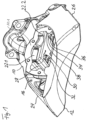
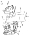
- eine perspektivische Ansicht eines bevorzugten Ausführungsbeispiels des erfindungsgemäßen Bremssattels, von der Felgenseite her gesehen,
- Figur 2
- die gleiche Ansicht wie
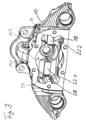
Figur 1 , jedoch von der Zuspannseite her gesehen, - Figur 3
- eine perspektivische Querschnittansicht auf den zuspannseitigen Abschnitt des Sattels,
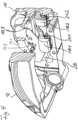
Figur 4- eine perspektivische Längsschnittansicht des Sattels,
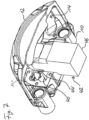
Figur 5- eine perspektivische Ansicht des Sattels von radial innen mit einem Bearbeitungswerkzeug,
- Figur 6
- die gleiche Ansicht wie
Figur 5 Figur 7- die gleiche Ansicht wie
Figur 6 , jedoch mit dem Bearbeitungswerkzeug in einer noch weiter fortgeschrittenen Position, - Figur 8
- eine perspektivische Längsschnittansicht mit dem Bearbeitungswerkzeug in einer Arbeitsstellung,
- die Figuren 9(a) bis (f)
- schematische Schnittansichten zur Erläuterung eines alternativen Herstellungsverfahrens.
- Figure 1
- a perspective view of a preferred embodiment of the brake caliper according to the invention, seen from the rim side,
- Figure 2
- the same view as
Figure 1 , but seen from the clamping side, - Figure 3
- a perspective cross-sectional view of the clamping-side section of the saddle,
- Figure 4
- a perspective longitudinal section view of the saddle,
- Figure 5
- a perspective view of the saddle from radially inside with a machining tool,
- Figure 6
- the same view as
Figure 5 , but with the editing tool in an advanced position, - Figure 7
- the same view as
Figure 6 , but with the editing tool in an even more advanced position, - Figure 8
- a perspective longitudinal section view with the processing tool in a working position,
- Figures 9(a) to (f)
- schematic sectional views to explain an alternative manufacturing process.
Der in den
In
Die beiden Sattelabschnitte 10 und 12 sind einstückig miteinander ausgebildet. Sie sind über Stege 24, 26 miteinander verbunden, die in eingebautem Zustand die Bremsscheibe übergreifen.The two
Im Inneren des Sattels bzw. an dem zuspannseitigen Sattelabschnitt 10 sind gemäß
Eine Flanschfläche 10.1 des zuspannseitigen Sattelschenkels 10, an der ein Verschlußrahmen angebracht werden kann, umläuft eine Axialöffnung 10.2, über die die Abstützflächen 22.1 und 22.2 zugänglich sind. Die Axialöffnung 10.2 dient auch dem späteren Einbringen der vorab erwähnten Teile der Zuspanneinrichtung.A flange surface 10.1 of the clamping-
Im folgenden ist ein erstes Beispiel eines Verfahrens zum Ausbilden der Abstützflächen 22.1 und 22.2 beschrieben:A first example of a method for forming the support surfaces 22.1 and 22.2 is described below:
Gemäß
Nachdem also das Bearbeitungswerkzeug 40 in
Bei dem gezeigten Ausführungsbeispiel sind die Führungsflächen 22.1 und 22.2 eben. Unter Verwendung beispielsweise eines Kugelkopffräsers als Bearbeitungswerkzeug können die genannten Abstützflächen auch nach Art einer Rinne mit kreisbogenförmiger Kontur ausgebildet werden.In the exemplary embodiment shown, the guide surfaces 22.1 and 22.2 are flat. Using, for example, a ball nose milling cutter as a processing tool, the support surfaces mentioned can also be designed in the manner of a channel with a circular arc-shaped contour.
Nach Ausbildung der Abstützflächen 22.1 und 22.2 wird das Bearbeitungswerkzeug 40 wieder aus dem Inneren des Sattels herausgefahren. Dabei erfolgen die oben beschriebenen Bewegungen in umgekehrter Reihenfolge.After the support surfaces 22.1 and 22.2 have been formed, the
Die Längsachse des Schenkels 44 ist mit der Bezugszahl 50 bezeichnet, vgl.
Im folgenden ist ein zweites Beispiel eines Verfahrens zum Ausbilden der Abstützflächen 22.1 und 22.2 unter Bezugnahme auf die
Das Bearbeitungswerkzeug 40 mit dem L-förmigen Halter 42 wird anders als nach dem ersten Beispiel in einer Stellung in die erste Ausnehmung 14 eingeführt, in der die Längsachse 50 des Schenkels 44 mit dem Bearbeitungswerkzeug 40 schräg bezüglich der Hauptebene 52 der (nicht gezeigten) Bremsscheibe angestellt ist. In dem beschriebenen Ausführungsbeispiel beträgt der Anstellwinkel α ca. 55°, vgl.
Gemäß
Wie der
Das Herausfahren der Halterung 42 mit dem Bearbeitungswerkzeug 40 erfolgt in umgekehrter Reihenfolge wie das Hineinfahren.The
Die in der obigen Beschreibung, den Ansprüchen sowie der Zeichnung offenbarten Merkmale der Erfindung können sowohl einzeln als auch in beliebiger Kombination für die Verwirklichung der Erfindung in ihren verschiedenen Ausführungsformen wesentlich sein. The features of the invention disclosed in the above description, the claims and the drawing can be essential for the implementation of the invention in its various embodiments, both individually and in any combination.
Claims (9)
- Method for producing a calliper of a calliper disc brake, in particular for commercial vehicles, the calliper having the following:an application-side calliper section (10) with at least one supporting face (22.1, 22.2) for absorbing clamping forces during braking, a rim-side calliper section (12) which is configured in one piece with the application-side calliper section, and a first recess (14) which lies between the two calliper sections and into which at least one brake disc protrudes at least in sections in the installed state, characterized in that,in order to configure the supporting face, a machining tool (40) is moved through the first recess into that region, in which the supporting face is to be configured, whereinthe machining tool (40) has an L-shaped holder (42) and, for moving into a working position, can be adjusted with regard to the calliper translationally and rotationally about an axis (48) in the direction of the longitudinal extent of one of the limbs of the "L" and about an axis which lies perpendicularly on both limbs (44, 46) of the "L".
- Method for producing a calliper of a calliper disc brake, in particular for commercial vehicles, the calliper having the following:an application-side calliper section (10) with at least one supporting face (22.1, 22.2) for absorbing clamping forces during braking,a rim-side calliper section (12) which is configured in one piece with the application-side calliper section, anda second recess (16) which lies between the two calliper sections for mounting/dismantling at least one brake lining,characterized in that,in order to configure the supporting face, a machining tool (40) is moved through the second recess into that region, in which the supporting face is to be configured.
- Method according to Claim 1 or 2, characterized in that the supporting face (22.1, 22.2) is planar at least in sections.
- Method according to one of the preceding claims, characterized in that the supporting face has the shape of a groove at least in sections.
- Method according to Claim 4, characterized in that the groove has an arcuate, in particular a circularly arcuate contour.
- Method according to one of the preceding claims, characterized in that, in a first step, the limb (44) of the "L" is moved with the machining tool into the first or the second recess (14, 16), to be precise with its longitudinal axis (50) parallel to the main plane of a brake disc which protrudes into the first recess in the installed state,in a second step, the holder is rotated about an axis (48) in the direction of the longitudinal extent of the other limb (44) of the "L", with the result that the machining tool (40) faces the application-side calliper section (10),in a third step, the machining tool is moved towards the application-side calliper section, and,in a fourth step, the supporting face (22.1, 22.2) is configured.
- Method according to one of the preceding claims, characterized in that, in a first step, the limb (44) of the "L" is moved with the machining tool (40) into the first or the second recess (14, 16), to be precise with its longitudinal axis (50) set at a predefined angle (α) with regard to the main plane (52) of a brake disc which protrudes into the first recess in the installed state, in a second step, the machining tool (40) is moved towards the application-side calliper section (10),in a third step, the machining tool (40) is pivoted with regard to the calliper about the axis which lies perpendicularly on both limbs (44, 46) of the "L", with the result that the limb of the "L" lies with the machining tool with its longitudinal axis (50) perpendicular with respect to the main plane (52) of a brake disc which protrudes into the first recess in the installed state, and,in a fourth step, the supporting face (22.1, 22.2) is configured.
- Method according to Claim 7, characterized in that the angle of attack (a) is from 30° to 80°, preferably from 40° to 70°, further preferably from 50° to 60°.
- Method according to one of the preceding claims, the application-side calliper section having at least one guide face (28, 30, 32, 34, 36, 37, 38, 39) for holding and/or guiding a brake lining, a pressure piece, at least one pressure spindle device and/or at least one pressure plunger device in the radial and/or circumferential directions of the brake disc,
characterized in that,
in order to configure the guide face, a machining tool is moved through the first or the second recess (14, 16) into that region, in which the guide face is to be configured.
Applications Claiming Priority (2)
| Application Number | Priority Date | Filing Date | Title |
|---|---|---|---|
| DE102008035753A DE102008035753A1 (en) | 2008-07-31 | 2008-07-31 | Method for producing a caliper, machining tool for carrying out the method, brake caliper produced by the method and disc brake with such a caliper |
| PCT/EP2009/005358 WO2010012414A1 (en) | 2008-07-31 | 2009-07-23 | Method for producing a brake caliper, machining tool for carrying out the method, brake caliper produced using the method, and disk brake having a caliper of said type |
Publications (3)
| Publication Number | Publication Date |
|---|---|
| EP2304261A1 EP2304261A1 (en) | 2011-04-06 |
| EP2304261B1 EP2304261B1 (en) | 2016-03-09 |
| EP2304261B2 true EP2304261B2 (en) | 2023-11-29 |
Family
ID=41016993
Family Applications (1)
| Application Number | Title | Priority Date | Filing Date |
|---|---|---|---|
| EP09777399.8A Active EP2304261B2 (en) | 2008-07-31 | 2009-07-23 | Method for producing a brake caliper |
Country Status (6)
| Country | Link |
|---|---|
| US (1) | US20110127120A1 (en) |
| EP (1) | EP2304261B2 (en) |
| CN (1) | CN102119286A (en) |
| BR (1) | BRPI0911030A2 (en) |
| DE (1) | DE102008035753A1 (en) |
| WO (1) | WO2010012414A1 (en) |
Families Citing this family (13)
| Publication number | Priority date | Publication date | Assignee | Title |
|---|---|---|---|---|
| JP5492176B2 (en) * | 2011-11-30 | 2014-05-14 | 曙ブレーキ工業株式会社 | Caliper body, caliper body torque receiving part grooving method |
| DE102012004605B4 (en) | 2012-03-02 | 2023-03-30 | Knorr-Bremse Systeme für Nutzfahrzeuge GmbH | Process and tool for machining bearing points in a brake caliper |
| DE102014115764A1 (en) | 2014-10-30 | 2016-05-04 | Knorr-Bremse Systeme für Nutzfahrzeuge GmbH | Cast iron brake caliper of a disc brake |
| DE102016115176A1 (en) | 2016-08-16 | 2018-02-22 | Bpw Bergische Achsen Kg | Method for internal machining of a brake caliper of a disc brake |
| DE102017102233A1 (en) | 2017-02-06 | 2018-08-09 | Bpw Bergische Achsen Kg | Method for internal machining of a brake caliper of a disc brake |
| IT201700079579A1 (en) * | 2017-07-14 | 2019-01-14 | Freni Brembo Spa | Brake caliper assembly and at least one pad |
| WO2019133596A1 (en) * | 2017-12-28 | 2019-07-04 | Kelsey-Hayes Company | Uni-directional anti-rotation member for a disc brake assembly with an electric parking brake |
| US10648522B2 (en) * | 2018-03-02 | 2020-05-12 | Arvinmeritor Technology, Llc | Brake caliper housing |
| EP3623656B1 (en) * | 2018-09-17 | 2021-01-27 | WABCO Europe BVBA | Brake calliper of a disk brake for motor vehicles |
| EP3987195B1 (en) * | 2019-06-19 | 2023-08-30 | ZF CV Systems Europe BV | Vehicle brake, in particular a utility vehicle compressed-air disk brake, and pressure piece for the same |
| CN110985568A (en) * | 2019-11-14 | 2020-04-10 | 浙江万安科技股份有限公司 | Clamp body, clamp body machining method and brake assembling method with clamp body |
| US20220333654A1 (en) * | 2021-04-20 | 2022-10-20 | Mando Corporation | Caliper brake |
| EP4160042A1 (en) * | 2021-09-30 | 2023-04-05 | Meritor Heavy Vehicle Braking Systems (UK) Limited | A machine tool head |
Citations (4)
| Publication number | Priority date | Publication date | Assignee | Title |
|---|---|---|---|---|
| DE19515063C2 (en) † | 1995-04-27 | 2002-06-06 | Knorr Bremse Systeme | Disc brake for vehicles, in particular road vehicles |
| JP2004353850A (en) † | 2003-05-30 | 2004-12-16 | Tokico Ltd | Method of machining disc brake caliper and method of machining axial groove in cylinder |
| DE102005006264B4 (en) † | 2004-11-30 | 2006-11-02 | Knorr-Bremse Systeme für Nutzfahrzeuge GmbH | Disc brake, in particular for a commercial vehicle |
| WO2007077206A1 (en) † | 2006-01-05 | 2007-07-12 | Sunstar Engineering Pte. Ltd. | Improved method of manufacturing callipers for disc brakes |
Family Cites Families (28)
| Publication number | Priority date | Publication date | Assignee | Title |
|---|---|---|---|---|
| GB818077A (en) | 1956-04-10 | 1959-08-12 | Girling Ltd | Improvements relating to disc brakes for vehicles |
| US3540165A (en) * | 1968-08-05 | 1970-11-17 | Bendix Corp | Device for rotatably holding a braking member having opposed braking surfaces for machining said surfaces |
| CA1030881A (en) | 1975-04-02 | 1978-05-09 | Donald D. Johannesen | Mechanically actuated disc brake |
| US3967705A (en) | 1975-04-02 | 1976-07-06 | The Bendix Corporation | Application adjuster for disc brake |
| US4400859A (en) * | 1980-12-23 | 1983-08-30 | Kearney & Trecker Corporation | Machining centers for machining tubular workpieces |
| JPS605406B2 (en) * | 1981-09-03 | 1985-02-12 | 日産自動車株式会社 | Constant velocity joint race groove processing equipment |
| DE3330942A1 (en) * | 1982-09-17 | 1984-03-22 | Scharmann GmbH & Co, 4050 Mönchengladbach | Horizontal boring and milling machine |
| US4638550A (en) * | 1982-09-17 | 1987-01-27 | Scharmann Gmbh & Co. | Horizontal drilling and milling machine |
| ES2004205A6 (en) * | 1986-02-01 | 1988-12-16 | Akebono Brake Ind | Caliper machining apparatus and method |
| DE4101514C2 (en) | 1991-01-19 | 2002-03-21 | Continental Teves Ag & Co Ohg | Part brake disc brake for the wheel suspension of a motor vehicle |
| US5632580A (en) * | 1995-03-31 | 1997-05-27 | The United States Of America As Represented By The Secretary Of The Navy | Milling machine extension |
| DE19636942C5 (en) | 1996-09-11 | 2010-07-29 | Wabco Radbremsen Gmbh | sliding saddle |
| GB9716363D0 (en) | 1997-08-02 | 1997-10-08 | Lucas Ind Plc | Improvements relating to disc brakes |
| SE522332C2 (en) * | 2000-05-31 | 2004-02-03 | Haldex Brake Prod Ab | Method of mounting a brake mechanism in a caliper and such caliper |
| DE10139900A1 (en) | 2000-08-17 | 2004-08-12 | Knorr-Bremse Systeme für Nutzfahrzeuge GmbH | Disc brake with tensioning system esp. for utility vehicles has turning lever with apertures for bearing shells/bearing elements to hold lever on caliper |
| US6481542B2 (en) * | 2001-02-19 | 2002-11-19 | Meritor Heavy Vehicle Systems, Llc. | Brake adjuster |
| SE523555C2 (en) | 2001-09-07 | 2004-04-27 | Haldex Brake Prod Ab | Modular writing brake for a vehicle |
| DE10152248B4 (en) * | 2001-10-23 | 2006-03-16 | Knorr-Bremse Systeme für Nutzfahrzeuge GmbH | Disc brake with electric motor operated adjustment system |
| DE10219148C1 (en) | 2002-04-29 | 2003-09-18 | Wabco Perrot Bremsen Gmbh | Linear tensioning system, for a disk brake, has a sliding support with a complementary contour to the support surfaces towards the tensioner shaft, to press the brake linings against the brake disk |
| US6811044B2 (en) * | 2002-09-26 | 2004-11-02 | Brian Walker | Shelf liner |
| DE102004002571B4 (en) * | 2003-04-28 | 2015-02-26 | Bpw Bergische Achsen Kg | Brake caliper for a disc brake |
| US6811004B1 (en) | 2003-05-09 | 2004-11-02 | Arvinmeritor Technology, Llc | Vehicle brake assembly having a bearing block closure and method of assembly therefor |
| DE102004042574A1 (en) * | 2004-09-02 | 2006-03-30 | Knorr-Bremse Systeme für Nutzfahrzeuge GmbH | Disc brake, in particular for commercial vehicles |
| US7326011B2 (en) * | 2005-09-23 | 2008-02-05 | The Boeing Company | Contouring right angle head for complex machining |
| DE102005054402B4 (en) | 2005-11-15 | 2007-12-06 | Knorr-Bremse Systeme für Nutzfahrzeuge GmbH | Disc brake, in particular for a commercial vehicle |
| DE102006033240B4 (en) | 2006-07-18 | 2016-03-24 | Lucas Varity S.R.O. | Attachment of the logo on the brake caliper of a disc brake |
| DE102007041658A1 (en) * | 2006-09-02 | 2008-03-13 | Bpw Bergische Achsen Kg | Disk brake for a vehicle comprises a spring element fixed to a brake caliper or housing on the outer side of a holding-down clamp |
| DE102007001960A1 (en) * | 2007-01-13 | 2008-07-17 | Bpw Bergische Achsen Kg | disc brake |
-
2008
- 2008-07-31 DE DE102008035753A patent/DE102008035753A1/en active Pending
-
2009
- 2009-07-23 CN CN2009801250124A patent/CN102119286A/en active Pending
- 2009-07-23 EP EP09777399.8A patent/EP2304261B2/en active Active
- 2009-07-23 BR BRPI0911030A patent/BRPI0911030A2/en not_active Application Discontinuation
- 2009-07-23 WO PCT/EP2009/005358 patent/WO2010012414A1/en active Application Filing
- 2009-07-23 US US13/056,115 patent/US20110127120A1/en not_active Abandoned
Patent Citations (4)
| Publication number | Priority date | Publication date | Assignee | Title |
|---|---|---|---|---|
| DE19515063C2 (en) † | 1995-04-27 | 2002-06-06 | Knorr Bremse Systeme | Disc brake for vehicles, in particular road vehicles |
| JP2004353850A (en) † | 2003-05-30 | 2004-12-16 | Tokico Ltd | Method of machining disc brake caliper and method of machining axial groove in cylinder |
| DE102005006264B4 (en) † | 2004-11-30 | 2006-11-02 | Knorr-Bremse Systeme für Nutzfahrzeuge GmbH | Disc brake, in particular for a commercial vehicle |
| WO2007077206A1 (en) † | 2006-01-05 | 2007-07-12 | Sunstar Engineering Pte. Ltd. | Improved method of manufacturing callipers for disc brakes |
Also Published As
| Publication number | Publication date |
|---|---|
| EP2304261B1 (en) | 2016-03-09 |
| DE102008035753A1 (en) | 2010-02-04 |
| US20110127120A1 (en) | 2011-06-02 |
| BRPI0911030A2 (en) | 2015-12-29 |
| CN102119286A (en) | 2011-07-06 |
| EP2304261A1 (en) | 2011-04-06 |
| WO2010012414A1 (en) | 2010-02-04 |
Similar Documents
| Publication | Publication Date | Title |
|---|---|---|
| EP2304261B2 (en) | Method for producing a brake caliper | |
| EP2529131B1 (en) | Disc brake | |
| EP2697015B1 (en) | Method for producing a brake carrier for a disc brake and brake carrier for a disc brake | |
| EP1989021A1 (en) | Method and device for the finish machining of composite camshafts and eccentric shafts | |
| EP1171259B1 (en) | Method and device for fracture-separating a workpiece | |
| WO2017036765A1 (en) | Disc brake having a synchronization unit | |
| DE3616695C2 (en) | Part-pad disc brake | |
| EP1974150B1 (en) | Disk brake | |
| EP3027926B2 (en) | Disk brake, in particular for utility vehicles, and brake pad of a disk brake of said type | |
| EP3109499B1 (en) | Disc brake, in particular for a commercial vehicle | |
| EP3500769B2 (en) | Method for machining the interior of a brake caliper of a disc brake | |
| EP2339197A1 (en) | Disc brake, brake calliper of such a brake and method for producing such a brake calliper | |
| DE2635823A1 (en) | DISC BRAKE | |
| DE102006030492B4 (en) | Method for grinding a compressor crankshaft | |
| DE102012006700A1 (en) | Wheel bearing tool i.e. two-piece press plate, for pressing wheel bearing in bearing bore of axle body bearing housing in brake caliper of disk brake of motor car, has circulating pressing surface in pressure contact with bearing | |
| DE202011103889U1 (en) | Installation on portal lathes for machining railway wheel sets with axlebox housings | |
| EP2519756B1 (en) | Brake calliper for a vehicle brake system and method and device for producing a brake calliper | |
| EP3046710B1 (en) | Method for chamfering and polishing toothed workpieces | |
| DE2756856A1 (en) | Floating calliper disc brake - has single non-round bolt in mating opening giving sliding movement | |
| DE102015000926B4 (en) | Process for manufacturing a brake caliper for a disc brake | |
| DE102017102233A1 (en) | Method for internal machining of a brake caliper of a disc brake | |
| EP1525589B1 (en) | Method and device for dismantling a control element of a boiling water reactor | |
| DE102004036614B3 (en) | Device for machine for processing brake discs has traverse fixed to machine at spacing greater than radius of outer circumference of brake disks | |
| DE102009023118A1 (en) | Take-up roller for winding a cylinder during paper manufacture comprises an external fixing unit and an internal fixing unit arranged along the central longitudinal axis of the roller | |
| DE102015008640A1 (en) | Rolling bearing assembly and method of manufacturing a rolling bearing assembly |
Legal Events
| Date | Code | Title | Description |
|---|---|---|---|
| PUAI | Public reference made under article 153(3) epc to a published international application that has entered the european phase |
Free format text: ORIGINAL CODE: 0009012 |
|
| 17P | Request for examination filed |
Effective date: 20101206 |
|
| AK | Designated contracting states |
Kind code of ref document: A1 Designated state(s): AT BE BG CH CY CZ DE DK EE ES FI FR GB GR HR HU IE IS IT LI LT LU LV MC MK MT NL NO PL PT RO SE SI SK SM TR |
|
| AX | Request for extension of the european patent |
Extension state: AL BA RS |
|
| DAX | Request for extension of the european patent (deleted) | ||
| 17Q | First examination report despatched |
Effective date: 20130102 |
|
| GRAP | Despatch of communication of intention to grant a patent |
Free format text: ORIGINAL CODE: EPIDOSNIGR1 |
|
| INTG | Intention to grant announced |
Effective date: 20151008 |
|
| GRAS | Grant fee paid |
Free format text: ORIGINAL CODE: EPIDOSNIGR3 |
|
| GRAA | (expected) grant |
Free format text: ORIGINAL CODE: 0009210 |
|
| STAA | Information on the status of an ep patent application or granted ep patent |
Free format text: STATUS: THE PATENT HAS BEEN GRANTED |
|
| AK | Designated contracting states |
Kind code of ref document: B1 Designated state(s): AT BE BG CH CY CZ DE DK EE ES FI FR GB GR HR HU IE IS IT LI LT LU LV MC MK MT NL NO PL PT RO SE SI SK SM TR |
|
| REG | Reference to a national code |
Ref country code: GB Ref legal event code: FG4D Free format text: NOT ENGLISH |
|
| REG | Reference to a national code |
Ref country code: AT Ref legal event code: REF Ref document number: 779770 Country of ref document: AT Kind code of ref document: T Effective date: 20160315 Ref country code: CH Ref legal event code: EP |
|
| REG | Reference to a national code |
Ref country code: IE Ref legal event code: FG4D Free format text: LANGUAGE OF EP DOCUMENT: GERMAN |
|
| REG | Reference to a national code |
Ref country code: DE Ref legal event code: R096 Ref document number: 502009012218 Country of ref document: DE |
|
| REG | Reference to a national code |
Ref country code: SE Ref legal event code: TRGR |
|
| RAP2 | Party data changed (patent owner data changed or rights of a patent transferred) |
Owner name: WABCO EUROPE BVBA |
|
| REG | Reference to a national code |
Ref country code: LT Ref legal event code: MG4D |
|
| REG | Reference to a national code |
Ref country code: NL Ref legal event code: MP Effective date: 20160309 |
|
| REG | Reference to a national code |
Ref country code: FR Ref legal event code: PLFP Year of fee payment: 8 |
|
| PG25 | Lapsed in a contracting state [announced via postgrant information from national office to epo] |
Ref country code: HR Free format text: LAPSE BECAUSE OF FAILURE TO SUBMIT A TRANSLATION OF THE DESCRIPTION OR TO PAY THE FEE WITHIN THE PRESCRIBED TIME-LIMIT Effective date: 20160309 Ref country code: GR Free format text: LAPSE BECAUSE OF FAILURE TO SUBMIT A TRANSLATION OF THE DESCRIPTION OR TO PAY THE FEE WITHIN THE PRESCRIBED TIME-LIMIT Effective date: 20160610 Ref country code: FI Free format text: LAPSE BECAUSE OF FAILURE TO SUBMIT A TRANSLATION OF THE DESCRIPTION OR TO PAY THE FEE WITHIN THE PRESCRIBED TIME-LIMIT Effective date: 20160309 Ref country code: NO Free format text: LAPSE BECAUSE OF FAILURE TO SUBMIT A TRANSLATION OF THE DESCRIPTION OR TO PAY THE FEE WITHIN THE PRESCRIBED TIME-LIMIT Effective date: 20160609 Ref country code: ES Free format text: LAPSE BECAUSE OF FAILURE TO SUBMIT A TRANSLATION OF THE DESCRIPTION OR TO PAY THE FEE WITHIN THE PRESCRIBED TIME-LIMIT Effective date: 20160309 |
|
| PG25 | Lapsed in a contracting state [announced via postgrant information from national office to epo] |
Ref country code: PL Free format text: LAPSE BECAUSE OF FAILURE TO SUBMIT A TRANSLATION OF THE DESCRIPTION OR TO PAY THE FEE WITHIN THE PRESCRIBED TIME-LIMIT Effective date: 20160309 Ref country code: LT Free format text: LAPSE BECAUSE OF FAILURE TO SUBMIT A TRANSLATION OF THE DESCRIPTION OR TO PAY THE FEE WITHIN THE PRESCRIBED TIME-LIMIT Effective date: 20160309 Ref country code: NL Free format text: LAPSE BECAUSE OF FAILURE TO SUBMIT A TRANSLATION OF THE DESCRIPTION OR TO PAY THE FEE WITHIN THE PRESCRIBED TIME-LIMIT Effective date: 20160309 Ref country code: LV Free format text: LAPSE BECAUSE OF FAILURE TO SUBMIT A TRANSLATION OF THE DESCRIPTION OR TO PAY THE FEE WITHIN THE PRESCRIBED TIME-LIMIT Effective date: 20160309 |
|
| REG | Reference to a national code |
Ref country code: GB Ref legal event code: 732E Free format text: REGISTERED BETWEEN 20160901 AND 20160907 |
|
| PG25 | Lapsed in a contracting state [announced via postgrant information from national office to epo] |
Ref country code: EE Free format text: LAPSE BECAUSE OF FAILURE TO SUBMIT A TRANSLATION OF THE DESCRIPTION OR TO PAY THE FEE WITHIN THE PRESCRIBED TIME-LIMIT Effective date: 20160309 Ref country code: IS Free format text: LAPSE BECAUSE OF FAILURE TO SUBMIT A TRANSLATION OF THE DESCRIPTION OR TO PAY THE FEE WITHIN THE PRESCRIBED TIME-LIMIT Effective date: 20160709 |
|
| PG25 | Lapsed in a contracting state [announced via postgrant information from national office to epo] |
Ref country code: CZ Free format text: LAPSE BECAUSE OF FAILURE TO SUBMIT A TRANSLATION OF THE DESCRIPTION OR TO PAY THE FEE WITHIN THE PRESCRIBED TIME-LIMIT Effective date: 20160309 Ref country code: RO Free format text: LAPSE BECAUSE OF FAILURE TO SUBMIT A TRANSLATION OF THE DESCRIPTION OR TO PAY THE FEE WITHIN THE PRESCRIBED TIME-LIMIT Effective date: 20160309 Ref country code: SM Free format text: LAPSE BECAUSE OF FAILURE TO SUBMIT A TRANSLATION OF THE DESCRIPTION OR TO PAY THE FEE WITHIN THE PRESCRIBED TIME-LIMIT Effective date: 20160309 Ref country code: PT Free format text: LAPSE BECAUSE OF FAILURE TO SUBMIT A TRANSLATION OF THE DESCRIPTION OR TO PAY THE FEE WITHIN THE PRESCRIBED TIME-LIMIT Effective date: 20160711 Ref country code: SK Free format text: LAPSE BECAUSE OF FAILURE TO SUBMIT A TRANSLATION OF THE DESCRIPTION OR TO PAY THE FEE WITHIN THE PRESCRIBED TIME-LIMIT Effective date: 20160309 |
|
| REG | Reference to a national code |
Ref country code: DE Ref legal event code: R026 Ref document number: 502009012218 Country of ref document: DE |
|
| PLBI | Opposition filed |
Free format text: ORIGINAL CODE: 0009260 |
|
| PLBI | Opposition filed |
Free format text: ORIGINAL CODE: 0009260 |
|
| PG25 | Lapsed in a contracting state [announced via postgrant information from national office to epo] |
Ref country code: BE Free format text: LAPSE BECAUSE OF NON-PAYMENT OF DUE FEES Effective date: 20160731 Ref country code: IT Free format text: LAPSE BECAUSE OF FAILURE TO SUBMIT A TRANSLATION OF THE DESCRIPTION OR TO PAY THE FEE WITHIN THE PRESCRIBED TIME-LIMIT Effective date: 20160309 |
|
| 26 | Opposition filed |
Opponent name: BPW BERGISCHE ACHSEN KG Effective date: 20161207 |
|
| PLAX | Notice of opposition and request to file observation + time limit sent |
Free format text: ORIGINAL CODE: EPIDOSNOBS2 |
|
| 26 | Opposition filed |
Opponent name: KNORR-BREMSE SYSTEME FUER NUTZFAHRZEUGE GMBH Effective date: 20161208 |
|
| PG25 | Lapsed in a contracting state [announced via postgrant information from national office to epo] |
Ref country code: DK Free format text: LAPSE BECAUSE OF FAILURE TO SUBMIT A TRANSLATION OF THE DESCRIPTION OR TO PAY THE FEE WITHIN THE PRESCRIBED TIME-LIMIT Effective date: 20160309 |
|
| PG25 | Lapsed in a contracting state [announced via postgrant information from national office to epo] |
Ref country code: BG Free format text: LAPSE BECAUSE OF FAILURE TO SUBMIT A TRANSLATION OF THE DESCRIPTION OR TO PAY THE FEE WITHIN THE PRESCRIBED TIME-LIMIT Effective date: 20160609 |
|
| REG | Reference to a national code |
Ref country code: CH Ref legal event code: PL |
|
| PG25 | Lapsed in a contracting state [announced via postgrant information from national office to epo] |
Ref country code: MC Free format text: LAPSE BECAUSE OF FAILURE TO SUBMIT A TRANSLATION OF THE DESCRIPTION OR TO PAY THE FEE WITHIN THE PRESCRIBED TIME-LIMIT Effective date: 20160309 |
|
| PG25 | Lapsed in a contracting state [announced via postgrant information from national office to epo] |
Ref country code: CH Free format text: LAPSE BECAUSE OF NON-PAYMENT OF DUE FEES Effective date: 20160731 Ref country code: LI Free format text: LAPSE BECAUSE OF NON-PAYMENT OF DUE FEES Effective date: 20160731 |
|
| REG | Reference to a national code |
Ref country code: IE Ref legal event code: MM4A |
|
| PLBB | Reply of patent proprietor to notice(s) of opposition received |
Free format text: ORIGINAL CODE: EPIDOSNOBS3 |
|
| PG25 | Lapsed in a contracting state [announced via postgrant information from national office to epo] |
Ref country code: SI Free format text: LAPSE BECAUSE OF FAILURE TO SUBMIT A TRANSLATION OF THE DESCRIPTION OR TO PAY THE FEE WITHIN THE PRESCRIBED TIME-LIMIT Effective date: 20160309 |
|
| REG | Reference to a national code |
Ref country code: FR Ref legal event code: PLFP Year of fee payment: 9 |
|
| PG25 | Lapsed in a contracting state [announced via postgrant information from national office to epo] |
Ref country code: IE Free format text: LAPSE BECAUSE OF NON-PAYMENT OF DUE FEES Effective date: 20160723 |
|
| PG25 | Lapsed in a contracting state [announced via postgrant information from national office to epo] |
Ref country code: LU Free format text: LAPSE BECAUSE OF NON-PAYMENT OF DUE FEES Effective date: 20160723 |
|
| REG | Reference to a national code |
Ref country code: AT Ref legal event code: MM01 Ref document number: 779770 Country of ref document: AT Kind code of ref document: T Effective date: 20160723 |
|
| PG25 | Lapsed in a contracting state [announced via postgrant information from national office to epo] |
Ref country code: AT Free format text: LAPSE BECAUSE OF NON-PAYMENT OF DUE FEES Effective date: 20160723 |
|
| PG25 | Lapsed in a contracting state [announced via postgrant information from national office to epo] |
Ref country code: HU Free format text: LAPSE BECAUSE OF FAILURE TO SUBMIT A TRANSLATION OF THE DESCRIPTION OR TO PAY THE FEE WITHIN THE PRESCRIBED TIME-LIMIT; INVALID AB INITIO Effective date: 20090723 Ref country code: CY Free format text: LAPSE BECAUSE OF FAILURE TO SUBMIT A TRANSLATION OF THE DESCRIPTION OR TO PAY THE FEE WITHIN THE PRESCRIBED TIME-LIMIT Effective date: 20160309 |
|
| PG25 | Lapsed in a contracting state [announced via postgrant information from national office to epo] |
Ref country code: MT Free format text: LAPSE BECAUSE OF FAILURE TO SUBMIT A TRANSLATION OF THE DESCRIPTION OR TO PAY THE FEE WITHIN THE PRESCRIBED TIME-LIMIT Effective date: 20160309 Ref country code: TR Free format text: LAPSE BECAUSE OF FAILURE TO SUBMIT A TRANSLATION OF THE DESCRIPTION OR TO PAY THE FEE WITHIN THE PRESCRIBED TIME-LIMIT Effective date: 20160309 Ref country code: MK Free format text: LAPSE BECAUSE OF FAILURE TO SUBMIT A TRANSLATION OF THE DESCRIPTION OR TO PAY THE FEE WITHIN THE PRESCRIBED TIME-LIMIT Effective date: 20160309 |
|
| REG | Reference to a national code |
Ref country code: FR Ref legal event code: PLFP Year of fee payment: 10 |
|
| APBM | Appeal reference recorded |
Free format text: ORIGINAL CODE: EPIDOSNREFNO |
|
| APBP | Date of receipt of notice of appeal recorded |
Free format text: ORIGINAL CODE: EPIDOSNNOA2O |
|
| APAH | Appeal reference modified |
Free format text: ORIGINAL CODE: EPIDOSCREFNO |
|
| APBM | Appeal reference recorded |
Free format text: ORIGINAL CODE: EPIDOSNREFNO |
|
| APBP | Date of receipt of notice of appeal recorded |
Free format text: ORIGINAL CODE: EPIDOSNNOA2O |
|
| APBQ | Date of receipt of statement of grounds of appeal recorded |
Free format text: ORIGINAL CODE: EPIDOSNNOA3O |
|
| APBQ | Date of receipt of statement of grounds of appeal recorded |
Free format text: ORIGINAL CODE: EPIDOSNNOA3O |
|
| PGFP | Annual fee paid to national office [announced via postgrant information from national office to epo] |
Ref country code: SE Payment date: 20190725 Year of fee payment: 11 |
|
| REG | Reference to a national code |
Ref country code: SE Ref legal event code: EUG |
|
| RAP4 | Party data changed (patent owner data changed or rights of a patent transferred) |
Owner name: ZF CV SYSTEMS EUROPE BV |
|
| PG25 | Lapsed in a contracting state [announced via postgrant information from national office to epo] |
Ref country code: SE Free format text: LAPSE BECAUSE OF NON-PAYMENT OF DUE FEES Effective date: 20200724 |
|
| PLAB | Opposition data, opponent's data or that of the opponent's representative modified |
Free format text: ORIGINAL CODE: 0009299OPPO |
|
| R26 | Opposition filed (corrected) |
Opponent name: BPW BERGISCHE ACHSEN KG Effective date: 20161207 |
|
| APBU | Appeal procedure closed |
Free format text: ORIGINAL CODE: EPIDOSNNOA9O |
|
| REG | Reference to a national code |
Ref country code: FR Ref legal event code: PLFP Year of fee payment: 14 |
|
| PLAY | Examination report in opposition despatched + time limit |
Free format text: ORIGINAL CODE: EPIDOSNORE2 |
|
| PLBC | Reply to examination report in opposition received |
Free format text: ORIGINAL CODE: EPIDOSNORE3 |
|
| PLAB | Opposition data, opponent's data or that of the opponent's representative modified |
Free format text: ORIGINAL CODE: 0009299OPPO |
|
| R26 | Opposition filed (corrected) |
Opponent name: BPW BERGISCHE ACHSEN KG Effective date: 20161207 |
|
| PLAT | Information related to reply to examination report in opposition deleted |
Free format text: ORIGINAL CODE: EPIDOSDORE3 |
|
| REG | Reference to a national code |
Ref country code: DE Ref legal event code: R081 Ref document number: 502009012218 Country of ref document: DE Owner name: ZF CV SYSTEMS EUROPE BV, BE Free format text: FORMER OWNER: WABCO RADBREMSEN GMBH, 68229 MANNHEIM, DE |
|
| P01 | Opt-out of the competence of the unified patent court (upc) registered |
Effective date: 20230528 |
|
| PGFP | Annual fee paid to national office [announced via postgrant information from national office to epo] |
Ref country code: FR Payment date: 20230620 Year of fee payment: 15 |
|
| PUAH | Patent maintained in amended form |
Free format text: ORIGINAL CODE: 0009272 |
|
| STAA | Information on the status of an ep patent application or granted ep patent |
Free format text: STATUS: PATENT MAINTAINED AS AMENDED |
|
| PGFP | Annual fee paid to national office [announced via postgrant information from national office to epo] |
Ref country code: GB Payment date: 20230601 Year of fee payment: 15 |
|
| 27A | Patent maintained in amended form |
Effective date: 20231129 |
|
| AK | Designated contracting states |
Kind code of ref document: B2 Designated state(s): AT BE BG CH CY CZ DE DK EE ES FI FR GB GR HR HU IE IS IT LI LT LU LV MC MK MT NL NO PL PT RO SE SI SK SM TR |
|
| REG | Reference to a national code |
Ref country code: DE Ref legal event code: R102 Ref document number: 502009012218 Country of ref document: DE |
|
| PGFP | Annual fee paid to national office [announced via postgrant information from national office to epo] |
Ref country code: DE Payment date: 20230531 Year of fee payment: 15 |