EP2302899A2 - Elektronische Vorrichtung und Programmtabellenanzeigeverfahren - Google Patents
Elektronische Vorrichtung und Programmtabellenanzeigeverfahren Download PDFInfo
- Publication number
- EP2302899A2 EP2302899A2 EP10172345A EP10172345A EP2302899A2 EP 2302899 A2 EP2302899 A2 EP 2302899A2 EP 10172345 A EP10172345 A EP 10172345A EP 10172345 A EP10172345 A EP 10172345A EP 2302899 A2 EP2302899 A2 EP 2302899A2
- Authority
- EP
- European Patent Office
- Prior art keywords
- channel
- program
- program table
- recording
- programs
- Prior art date
- Legal status (The legal status is an assumption and is not a legal conclusion. Google has not performed a legal analysis and makes no representation as to the accuracy of the status listed.)
- Granted
Links
Images



Classifications
-
- H—ELECTRICITY
- H04—ELECTRIC COMMUNICATION TECHNIQUE
- H04N—PICTORIAL COMMUNICATION, e.g. TELEVISION
- H04N21/00—Selective content distribution, e.g. interactive television or video on demand [VOD]
- H04N21/40—Client devices specifically adapted for the reception of or interaction with content, e.g. set-top-box [STB]; Operations thereof
- H04N21/41—Structure of client; Structure of client peripherals
- H04N21/426—Internal components of the client ; Characteristics thereof
- H04N21/42607—Internal components of the client ; Characteristics thereof for processing the incoming bitstream
- H04N21/4263—Internal components of the client ; Characteristics thereof for processing the incoming bitstream involving specific tuning arrangements, e.g. two tuners
-
- H—ELECTRICITY
- H04—ELECTRIC COMMUNICATION TECHNIQUE
- H04N—PICTORIAL COMMUNICATION, e.g. TELEVISION
- H04N21/00—Selective content distribution, e.g. interactive television or video on demand [VOD]
- H04N21/40—Client devices specifically adapted for the reception of or interaction with content, e.g. set-top-box [STB]; Operations thereof
- H04N21/41—Structure of client; Structure of client peripherals
- H04N21/422—Input-only peripherals, i.e. input devices connected to specially adapted client devices, e.g. global positioning system [GPS]
- H04N21/42204—User interfaces specially adapted for controlling a client device through a remote control device; Remote control devices therefor
- H04N21/42206—User interfaces specially adapted for controlling a client device through a remote control device; Remote control devices therefor characterized by hardware details
- H04N21/4221—Dedicated function buttons, e.g. for the control of an EPG, subtitles, aspect ratio, picture-in-picture or teletext
-
- H—ELECTRICITY
- H04—ELECTRIC COMMUNICATION TECHNIQUE
- H04N—PICTORIAL COMMUNICATION, e.g. TELEVISION
- H04N21/00—Selective content distribution, e.g. interactive television or video on demand [VOD]
- H04N21/40—Client devices specifically adapted for the reception of or interaction with content, e.g. set-top-box [STB]; Operations thereof
- H04N21/43—Processing of content or additional data, e.g. demultiplexing additional data from a digital video stream; Elementary client operations, e.g. monitoring of home network or synchronising decoder's clock; Client middleware
- H04N21/432—Content retrieval operation from a local storage medium, e.g. hard-disk
- H04N21/4325—Content retrieval operation from a local storage medium, e.g. hard-disk by playing back content from the storage medium
-
- H—ELECTRICITY
- H04—ELECTRIC COMMUNICATION TECHNIQUE
- H04N—PICTORIAL COMMUNICATION, e.g. TELEVISION
- H04N21/00—Selective content distribution, e.g. interactive television or video on demand [VOD]
- H04N21/40—Client devices specifically adapted for the reception of or interaction with content, e.g. set-top-box [STB]; Operations thereof
- H04N21/43—Processing of content or additional data, e.g. demultiplexing additional data from a digital video stream; Elementary client operations, e.g. monitoring of home network or synchronising decoder's clock; Client middleware
- H04N21/433—Content storage operation, e.g. storage operation in response to a pause request, caching operations
- H04N21/4334—Recording operations
-
- H—ELECTRICITY
- H04—ELECTRIC COMMUNICATION TECHNIQUE
- H04N—PICTORIAL COMMUNICATION, e.g. TELEVISION
- H04N21/00—Selective content distribution, e.g. interactive television or video on demand [VOD]
- H04N21/40—Client devices specifically adapted for the reception of or interaction with content, e.g. set-top-box [STB]; Operations thereof
- H04N21/47—End-user applications
- H04N21/482—End-user interface for programme selection
- H04N21/4821—End-user interface for programme selection using a grid, e.g. sorted out by channel and broadcast time
Definitions
- One embodiment of the invention relates to an electronic apparatus and a program table display method.
- Digital broadcast waves contain service information data as well as video data and audio data. Electronic apparatuses receiving the digital broadcast waves can realize various functions based on the service information data.
- a digital broadcast receiving apparatus which can create an electronic program table where information about broadcast programs are described based on service information data, and display the electronic program table on a part of a screen which is displaying a program (for example, see JP-A-11-112899 (KOKAI)).
- an electronic program table can be created based on service information data about the recorded programs.
- multiple programs recorded simultaneously are played back continuously in accordance with what times they were recorded. That is, a program to be played back is changed without user designating programs to-be-viewed newly from the program table. It is therefore requested to indicate a program, which is being played back, exactly on the electronic program table even when recorded programs are played back continuously.
- One of objects of the invention is to provide an electronic apparatus and a program table display method by which a program which is being played back among recorded programs recorded simultaneously can be displayed more exactly.
- an electronic apparatus comprising:
- a program table display method comprising:
- a television broadcast receiving apparatus 100 will be described as an electronic apparatus according to the embodiment of the invention by way of example.
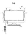
- Fig. 1 is a diagram showing an appearance of the television broadcast receiving apparatus 100 according to this embodiment.
- the television broadcast receiving apparatus will be described as an electronic apparatus according to the embodiment of the invention by way of example, but the electronic apparatus according to the invention is not limited thereto. That is, the electronic apparatus according to the invention may be any apparatus as long as the apparatus is provide with a broadcast receiving function.
- the apparatus may be a broadcast receiving apparatus, a cellular phone including a broadcast receiving function, a personal computer including a broadcast receiving function, a video recording apparatus mounted with a broadcast receiving apparatus, etc.
- broadcasting is not limited to a broadcast to be received as a radio wave propagated in the air, but may be one to be distributed from a broadcast station through a cable or a network such as an IP (Internet Protocol) network so that programs can be received.
- IP Internet Protocol
- the television broadcast receiving apparatus 100 includes a thin cabinet 110 and a support base 120 supporting the cabinet 110.
- the cabinet 110 houses electronic devices including tuners 3 which will be described later.
- a video display module 130 is disposed in a front center space of the cabinet 110, and speakers 140 are disposed on opposite side surfaces of the cabinet 110 to play back stereo audio.
- the video display module 130 is, for example, an SED (Surface-conduction Electron-emitter Display) panel, an LCD (Liquid Crystal Display) panel, or the like.
- a reception module 24 for receiving an operation signal sent from a remote controller 150 by wireless is provided in a front lower space of the cabinet 110.
- an operation module 23 including a power switch and so on is disposed in a side surface of the cabinet 110 of the television broadcast receiving apparatus 100.
- the television broadcast receiving apparatus 100 is supplied with power from the outside through a not-shown plug, and receives various kinds of broadcast waves through an antenna 1 which will be described later. Signals of the received broadcast waves are decoded by a signal processing module 12 so that video signals and audio signals are outputted.
- the video display module 130 processes the decoded video signals to display video, while the speakers 140 process the decoded audio signals to output audio.
- electronic devices including tuners are housed in the cabinet 110, but the invention is not limited thereto. That is, the electronic devices including the tuners 3 may be housed in another housing than the cabinet 110. In this case, this housing is connected to the television broadcast receiving apparatus 100 so that video and audio can be outputted by the video display module 130 and the speakers 140 provided in the television broadcast receiving apparatus 100.
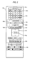
- Fig. 2 is a diagram showing an appearance of the remote controller 150 provided in the television broadcast receiving apparatus according to this embodiment.
- the remote controller 150 is designed to have a power key 150a, broadcast switch keys 150b, direct channel selection keys 150c, a volume control key 150d, a channel up/down key 150e, a focus key 150f, a decide key 150g, blue, red, green and yellow color keys 150h, special playback keys 150i, a screen display key 150j, a time shift key 150k and a program table key 1501.
- the power key 150a is a key for giving an instruction to power on/off the television broadcast receiving apparatus 100.
- the broadcast switch keys 150b are keys each for giving an instruction to switch a broadcast to be displayed on the television broadcast receiving apparatus 100 among digital terrestrial broadcasting, BS digital broadcasting and CS digital broadcasting.
- Each direct channel selection key 150c is a key for giving an instruction to display a channel corresponding to the key on the television broadcast receiving apparatus 100.
- the volume control key 150d is a key for giving an instruction to change the volume to be outputted from the speakers 140.
- the channel up/down key 150c is a key for giving an instruction to change a channel to be displayed on the television broadcast receiving apparatus 100 in channel number order.
- the focus key 150f is a key for giving an instruction to move a focus 45 ( Fig. 6 ) to be displayed on the video display module 130.
- the decide key 150g is a key for giving an instruction to select an item where the focus key 150f is located.
- Each color key 150h is a key each for giving an instruction for operation corresponding to an operation guide displayed on the screen and assigned to the color key.
- Each special playback key 150i is a key for giving an instruction for special playback such as fast forward, rewind, stop, play back, skip to next program, skip to previous program, etc.
- the screen display key 150j is a key for displaying a banner or the like indicating a playback position in a recorded program.
- the time shift key 150k is a key for displaying a past program table 44 ( Fig. 6 ), which shows programs recorded simultaneously by a second recording method which will be described later.
- the past program table 44 is displayed.
- the program table key 1501 is a key for displaying a program table including one week programs since the current time based on EPG (Electronic Program Guide) information.
- EPG Electronic Program Guide
- the past program table 44 can be displayed. As soon as any key is operated, an operation signal indicating the contents of an instruction corresponding to the key is supplied to a control module 18 shown in Fig. 3 , through the reception module 24.
- Fig. 3 is a functional block diagram of the television broadcast receiving apparatus 100 according to this embodiment. Functions of the television broadcast receiving apparatus 100 displaying the past program table 44 according to this embodiment will be described with reference to Fig. 3 .
- the television broadcast receiving apparatus 100 includes the antenna 1, an input terminal 2, the tuners 3, a TS (Transport Stream) processing module 11, the signal processing module 12, a graphic processing module 13, an OSD (On Screen Display) signal generating module 14, an audio processing module 15, a video processing module 16, an HDD (Hard Disk Drive) 17, the control module 18, the operation module 23, the reception module 24, a first card I/F (Interface) 25, a first card holder 26, a second card I/F 28, a second card holder 29, a brightness sensor 31, a communication I/F 32, a LAN terminal 33, a USB I/F 34, a USB terminal 35, an i.LINK I/F 36, an i.LINK terminal 37, an HDMI I/F 38, an HDMI terminal 39, the video display module 130 and the speakers 140.
- a TS Transport Stream
- the signal processing module 12 a graphic processing module 13, an OSD (On Screen Display) signal generating module 14, an audio processing module 15, a video processing module 16, an HDD (Hard Disk Drive)
- control module 18 includes a ROM (Read Only Memory) 19, a RAM (Random Access Memory) 20, a nonvolatile memory 21, a recording/playback control module 22, a channel switch control module 40, and a CPU (Central Processing Unit).
- ROM Read Only Memory
- RAM Random Access Memory
- nonvolatile memory nonvolatile memory
- recording/playback control module 22
- channel switch control module 40 channel switch control module 40
- CPU Central Processing Unit
- the antenna 1 is an antenna which is designed to be able to receive digital terrestrial broadcasting, BS digital broadcasting and CS digital broadcasting as broadcasting formats.
- the input terminal 2 supplies a broadcast signal received by the antenna 1 to the multiple tuners 3.
- each tuner 3 selects a broadcast signal of a desired channel from three kinds of digital terrestrial broadcasting, BS digital broadcasting and CS digital broadcasting, demodulates the broadcast signal of the selected channel (by OFDM (Orthogonal Frequency Division Multiplexing) demodulation in the case of digital terrestrial broadcasting or by PSK (Phase Shift Keying) demodulation in the case of BS digital broadcasting or CS digital broadcasting) to thereby obtain a TS (Transport Stream) containing a desired program, and supplies the TS to the TS processing module 11.
- OFDM Orthogonal Frequency Division Multiplexing
- PSK Phase Shift Keying
- the multiple tuners 3 are provided and will be referred to as tuners 3A, 3B and 3C respectively in accordance with broadcast waves to be received. If there is no need to distinguish the tuners 3A to 3C in particular, each tuner will be referred to as "tuner 3" simply.
- the tuner 3A serves for viewing, and tuners 3B and 3C serve for recording. Description will be made later on a difference between recording methods using broadcast signals of channels selected by the tuners 3B and 3C respectively.
- the multiple TSs of selected channels are supplied from the tuners 3 to the TS processing module 11.
- the TS processing module 11 remultiplexes the TSs into one TS and supplies the remultiplexed TS to the signal processing module 12.
- the TSs of channels selected by the tuners 3B and 3B are supplied from the tuners 3 to the TS processing module 11.
- the TS processing module 11 remultiplexes the TSs into one TS and supplies the remultiplexed TS to the signal processing module 12.
- the signal processing module 12 applies suitable digital signal processing to the TS into which TSs of the multiple channels are remultiplexed and which is supplied from the TS processing module 11.
- the TS to which the digital signal processing has been applied is separated into a data signal, a video signal and an audio signal.
- the separated video signal is outputted to the graphic processing module 13, the audio signal is outputted to the audio processing module 15, and the data signal is outputted to the OSD signal generating module 14 or the control module 18.
- the TS remultiplexed by the TS processing module 11 is supplied to the control module 18 for recording.
- the data signal contains various pieces of information about broadcast programs.
- the information about the programs includes time information.
- time information In Japanese digital terrestrial broadcasting, ARIB STD-B10, which is a standard established by the Association of Radio Industries and Businesses (ARIB), defines a time and date table (TDT) and a time offset table (TOT) as tables of program arrangement information.
- the time offset table (TOT) contains information of offset time serving when summer time is applied.
- a time and date offset table (TOT) is used as current date and current time in this specification.
- TOT time and date offset table
- ARIB TR-B 14 defining operation regulation for digital terrestrial broadcasting in Japan
- a default period with which the time and date offset table (TOT) should be transmitted is defined as 5 seconds.
- the TOT is transmitted with a period of 5 seconds.
- EPG information is another piece of the information about programs contained in the data signal.
- the EPG information includes channel information, a channel number, a program name, a schedule, etc.
- the EPG information is used for generating a program table of one week programs since the current time and the past program table 44 of recorded programs.
- the past program table 44 is generated by a past program table generating module 50.
- the graphic processing module 13 performs processing for decoding the digital video signal outputted from the signal processing module 12.
- the decoded video signal is superposed on and combined with an OSD signal outputted from the OSD signal generating module 14.
- the resulting combined signal is outputted to the video processing module 16.
- the graphic processing module 13 can also output the decoded video signal or the OSD signal to the video processing module 16 selectively.
- the OSD signal generating module 14 Under the control of the control module 18, the OSD signal generating module 14 generates an OSD signal for displaying a UI (User Interface) screen or the like.
- the aforementioned data signal separated from the digital broadcast signal by the signal processing module 12 is converted into an OSD signal in a suitable format by the OSD signal generating module 14 and outputted to the graphic processing module 13.
- the audio processing module 15 converts the audio signal supplied from the signal processing module 12, into an analog audio signal in a format with which the audio signal can be played back by the speakers 140.
- the converted analog audio signal is supplied to the speakers 140 and played back thereby.
- the video processing module 16 converts the signal outputted from the graphic processing module 13, into an analog video signal in a format with which the video signal can be played back on the video display module 130.
- the converted analog video signal is outputted to the video display module 130.
- the HDD 17 stores TSs of every channel under the control of the recording/playback control module 22.
- the recording state of the HDD 17 will be described later with reference to Fig. 4 .
- the control module 18 starts up a system control program and various processing programs recorded in advance on the ROM 19 in accordance with an operation signal inputted from the operation module 23 or an operation signal transmitted from the remote controller 150 and received through the reception module 24.
- the control module 18 controls operation of each module of the apparatus with the RAM 20 as a working memory in accordance with the programs started up.
- the ROM 19 is a memory for storing the system control program and various processing programs to be executed by the CPU.
- the RAM 20 is a so-called working memory where the CPU will expand various programs.
- the nonvolatile memory 21 stores various setting information, control information, etc. required for controlling operation of each module.
- the nonvolatile memory 21 stores channel information of a broadcast viewed immediately before playback of a recorded program.
- the recording/playback control module 22 controls the function of the television broadcast receiving apparatus 100 to record a program and play back the recorded program. That is, the recording/playback control module 22 demultiplexes the TS, into which the TSs of the multiple channels have been remultiplexed and which is outputted from the TS processing module 11, into respective TSs of the respective channels. The demultiplexed TSs are recorded on the HDD 17.
- the recording/playback control module 22 carries out control to play back the recorded data, so that each TS of each channel stored in the HDD 17 can be read, played back and then displayed on the video display module 130, or audio can be outputted from the speakers 140.
- the LAN terminal 33 is provided as a port for exclusive use in an LAN HDD, information of programs based on high-definition image quality can be stably recorded on the HDD 17 without being affected by the environment of another network, the network use condition, etc.
- the television broadcast receiving apparatus 100 has two kinds of recording methods-
- a first recording method is a recording method for designating programs to be recorded individually or for designating the start and end of recording in an arbitrary time. That is, in the first recording method, a broadcast wave of a designated program is received and the TS corresponding to this broadcast wave is recorded on the HDD 17.
- This method is the same recording method as in a related-art HDD recorder or the like where programs to be recorded should be designated individually.
- Each tuner 3B is used as a tuner for receiving a broadcast wave for use in the first recording method.
- the second recording method is not for designating programs individually, but for designating conditions such as channels, hours, days, etc. and recording all the programs that satisfy the conditions. That is, the multiple broadcast waves corresponding to the conditions are received, and the TSs corresponding to these broadcast waves are recorded on the HDD 17 in parallel and channel by channel.
- Each tuner 3C is used as a tuner for receiving a broadcast wave for use in the second recording method.
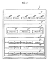
- Fig. 4 is a conceptual diagram of the recording state of the HDD 17 in this embodiment. Recording states of programs recorded by the aforementioned two kinds of recording methods will be described with reference to Fig. 4 .
- the recording/playback control module 22 divides the HDD 17 into a first recording area 171 and a second recording area 172 and performs recording thereon. TSs of programs recorded by the first recording method are stored in the first recording area 171. A time information table 42 created for each channel and each TS 43 of each channel recorded by the second recording method are recorded in the second recording area 172.
- TSs of programs a to e recorded in accordance with programs individually designated by the user are stored in the first recording area 171 (41 a to 41e).
- the TS of each program a to e is stored together with channel information about the program and program information including the name of the program.
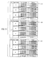
- Fig. 5 is a conceptual diagram of the recording state of time information table 42 in this embodiment.
- Time information tables 42A to 42C correspond to Channels 1 to 3 respectively.
- Channel information, program information, time information and address are recorded in each time information table 42 so as to be associated with one another.
- the time information tables 42 are created every 0.5 seconds, for example, correspondingly to the GOP (Group Of Picture) interval of broadcasting of MPEG (Moving Picture Experts Group) 2.
- the address is a logical address or a physical address.
- Programs A to P recorded in Channels 1 to 3 with designated conditions of time ranges, days of the week, or the like are stored as TSs 43 (TS43A, TS43B, TS43C) for the respective channels in the second recording area 172.
- TSs 43 (TS43A, TS43B, TS43C) for the respective channels in the second recording area 172.
- the recording capacity of the second recording area 172 has reached its limit, recording is continued while parts in the TSs 43 are deleted sequentially in an older recording time order.
- parts in the time information tables 42 are also deleted sequentially in an older recording time order, and parts for a program recorded newly are created and stored.
- the time information tables 42 are not always recorded in the second recording area 172. That is, the time information tables 42 may be recorded on the nonvolatile memory 21 or on recording media connected through various interfaces.
- the television broadcast receiving apparatus 100 has two kinds of playback methods as methods for playing back recorded programs.
- first playback method there is a method for playing back only one program selected from programs stored in the first recording area 171. That is, in the first playback method, a list of programs a to e stored in the first recording area 171 is displayed, and one program selected based on the displayed list is played back.
- the second playback method there is a method for playing back TSs of the multiple channels stored in the second recording area 172 continuously, sequentially, switchably among the channels and along their recording times. That is, when a channel being played back is switched to another selected channel during playback of any one of TSs 43A to 43C of Channels 1 to 3 stored in the second recording area 172, the TS of the selected channel as a destination of the channel switching is read from the second recording area 172 and displayed to start at a time point recorded in almost the same time as the time of the channel which had been played back till then.
- a program in the switched channel can be viewed retrospectively as if broadcasting of the program were viewed in real time.
- the phrase "almost the same time” means about 10 seconds around the recording time corresponding to the position of playback. It takes a few seconds to display video on the video display module 130 after starting playback of a TS 43. As a result, when playback is moved to a position of a program recorded in the same recording time, actually displaying the video of the program may be delayed by a few seconds. Therefore, the position of the program may be moved to a position recorded a few seconds earlier than the time information of the TS 43 which is being played back when the channel switching operation is performed. When the position is moved to the few seconds earlier position of the TS 43, a video image recorded in the same time as the recording time of the channel which had been viewed before the channel switching operation can be displayed actually.
- the position of the program may be moved to a position recorded a few seconds later than the time information of the TS 43 which is being played back when the channel switching operation is performed.
- the position is moved to the few seconds later position of the TS 43, the operation to switch the channel when a broadcast is being viewed in real time can be played back retrospectively.
- the second playback method is carried out in the case where the time shift key 150k is pushed down to designate a program in the past program table 44 as shown in Fig. 6 . That is, the second playback method is referred to as "time shift mode". That is, when a program to be played back is selected from programs A to P recorded by the second recording method as shown in the past program table 44, playback is carried out by the second playback method. According to the time shift mode using the second playback method, the selected recorded program is first played back and other recorded programs are then played back continuously, sequentially and along their recording times.
- the past program table 44 is displayed.
- a program to be played back can be switched to the designated program.
- Fig. 6 is a diagram showing an example of the past program table 44 in this embodiment.
- the past program table 44 includes the focus 45, a table 46, a recording time indicator 47, a channel indicator 48 and a playback time indicator 49.
- the focus 45 moves on the table 46 in accordance with operation on the focus key 150f.
- the focus 45 may be designed to indicate a difference color in the frame or inside of a column of a selected program from that in any program column in order to show that the program has been selected.
- the focus 45 is applied to the position of the latest recorded program of the viewed channel.
- the focus 45 is applied to the position of the latest recorded program of the channel whose channel number is the smallest of channels recorded by the second recording method.
- the past program table 44 is displayed.
- a program to be played back can be switched to the designated program.
- the past program table 44 is displayed.
- the focus 45 is applied to the position of a recorded program which is being played back when the program table key 1501 is pushed down.
- the table 46 is a table for displaying recorded programs.
- the ordinate of the table 46 serves as the recording time indicator 47, and the abscissa of the table 46 serves as the channel indicator 48.
- Program information determined from channel information and time information based on EPG information is displayed in each cell of the table 46.
- the recording time indicator 47 displays a table where up to six hours of recorded programs among recorded programs recorded by the second recording method are tracked back from the recording time of the latest recorded program. When the recording time does not reach six hours, only recorded programs are displayed.
- the channel indicator 48 indicates channels of TSs 43 stored in the second recording area 172.
- the playback time indicator 49 indicates recording time when a program being played back by the second playback method was recorded.
- the recording/playback control module 22 carries out playback of the program to which the focus 45 is applied.
- the recording/playback control module 22 first play backs the program C.
- the recording/playback control module 22 sequentially play backs the program D.
- the program being recorded is displayed in the lowest row of the table 46.
- a part being recorded is displayed in a different manner from the other part on the table 46.
- the operation module 23 accepts an operation signal in accordance with user's operation, and supplies the operation signal to the control module 18.
- the reception module 24 accepts an operation signal in accordance with user's operation on the remote controller 150, and supplies the operation signal to the control module 18.
- the first card holder 26 is connected to the control module 18 through the first card I/F 25.
- a first card 27 can be attached to the first card I/F 25.
- the first card 27 is a recording medium such as an SD (Secure Digital) memory card, an MMC (MultiMedia Card), a CF (Compact Flash) (registered trademark) card, etc.
- the first card 27 attached to the first card holder 26 and the control module 18 can transmit information to each other through the first card I/F 25.
- the control module 18 can store data of images, music, broadcast programs, etc. into the first card 27.
- the control module 18 reads out data of images, music, broadcast programs, etc. stored in the first card 27, and then decoding processing is performed on the read data in the audio processing module 15, the video processing module 16, etc. so that the data can be displayed as video on the video display module 130 or outputted as audio from the speakers 140.
- the second card holder 29 is connected to the control module 18 through the second card I/F 28.
- a second card 30 can be attached to the second card I/F 28.
- the second card 30 is a recording medium, for example, for recording contract information of broadcast reception contracts or the like.
- the second card 30 attached to the second card holder 29 and the control module 18 can transmit information to each other through the second card I/F 28.
- the brightness sensor 31 is disposed in the front surface of the cabinet 110.
- the brightness sensor 31 detects brightness of the environment where the television broadcast receiving apparatus 100 is installed. A result of the detection is supplied to the control module 18.
- the control module 18 controls the luminance of the video display module 130 based on the supplied detection result about the brightness.
- the LAN (Local Area Network) terminal 33 is connected to the control module 18 through the communication I/F 32.
- the LAN terminal 33 is used as a port for exclusive use in an LAN HDD using Ethernet (registered trademark).
- Ethernet registered trademark
- the control module 18 serves as a DHCP (Dynamic Host Configuration Protocol) server, which assigns an IP (Internet Protocol) address to the LAN HDD connected to the LAN terminal 33, and controls the LAN HDD with the IP address.
- DHCP Dynamic Host Configuration Protocol
- a recording medium such as a hard disk, a DVD (optical disk), etc. can be attached to an apparatus such as an HDD, a PC, a DVD recorder, etc. connected to the control module 18 through the communication I/F 32.
- the control module 18 can store data of images, music, broadcast programs, etc. into the recording medium through a hub and an apparatus connected to the hub.
- the control module 18 reads out the data of images, music, broadcast programs, etc. stored in the recording medium, and play backs the read data.
- the data can be displayed as video on the video display module 130 or outputted as audio from the speakers 140.
- the USB (Universal Serial Bus) terminal 35 is connected to the control module 18 through the USB I/F 34.
- the USB terminal 35 is used as a general USB port.
- a cellular phone, a digital camera, a card reader/writer for various memory cards, an HDD, a keyboard, etc. are connected to the USB terminal 35 through a hub.
- the control module 18 and an apparatus connected thereto through the USB terminal 35 and the USB I/F 34 can transmit information to each other.
- the i.LINK terminal 37 is connected to the control module 18 through the i.LINK I/F 36.
- an AV-HDD, a D(Digital)-VHS (Video Home System) or the like is serial-connected to the i.LINK terminal 37.
- the control module 18 and an apparatus connected thereto through the i.LINK terminal 37 and the i.LINK I/F 36 can transmit information to each other.
- the HDMI terminal 39 is connected to the control module 18 through the HDMI I/F 38.
- a personal computer, a liquid crystal display, an AV amplifier or the like is connected to the HDMI terminal 39.
- the control module 18 and an apparatus connected thereto through the HDMI terminal 39 and the HDMI I/F 3 8 can transmit information to each other.
- the channel switch control module 40 controls the operation of switching a channel during playback by any one of the first and second playback methods.
- An instruction to perform the operation of switching the channel is given by any one of the direct channel selection keys 150c and the channel up/down key 150e.
- the operation of switching the channel varies depending on which playback method is being used.
- the program is switched to a program which is being broadcast currently in the same channel. That is, when a designated program is being played back, a program of another channel was not always recorded at the same time as the program being played back. Therefore, a program which is being broadcast currently in the same channel is switched without switching the channel from one recorded program to another.
- the program When a program is being played back by the second playback method, the program is changed to a program of another channel which was recorded at the same time as the program being played back.
- one recorded channel is switched to another recorded channel based on the playback time, a program in the switched channel can be viewed retrospectively as if broadcasting of the program were viewed in real time.
- warning indicating that the channel cannot be switched to the designated channel is displayed.
- the channel switch control module 40 acquires channel information of a channel viewed immediately before the playback of the recorded program, from the nonvolatile memory 21.
- the channel switch control module 40 changes the program to a program being currently broadcast in the channel based on the channel information. Alternatively, the program may be changed to a program being currently broadcast in one of adjacent channels to the channel viewed immediately before the playback of the recorded program.
- Fig. 7 is a schematic diagram showing that a channel being played back by the second playback method is switched according to this embodiment.
- the operation of switching a channel which is being played back by the second playback method will be described with reference to Fig. 7 .
- the following description will be made in the case where the position is changed to a position of a TS 43 of a destination channel to be switched which was recorded at the same time as the playback time.
- the position may be regarded as a position which was recorded at almost the same time.
- Fig. 7 shows recorded programs stored in the second recording area 172 channel by channel, where the ordinate is set as a temporal axis.
- Fig. 7 depicts that programs broadcast from 4 p.m. to 10 p.m. in Channel 1 (CH1), Channel 2 (CH2) and Channel 3 (CH3) were recorded.
- CH1 Channel 1
- CH2 Channel 2
- CH3 Channel 3
- a program A was recorded from 4 p.m. to 5 p.m.
- a program B was recorded from 5 p.m. to 6 p.m.
- a program C was recorded from 6 p.m. to 7 p.m.
- a program D was recorded from 7 p.m. to 8 p.m.
- a program E was recorded from 8 p.m. to 10 p.m.
- Channel 2 of the direct channel selection keys 150c is pushed down when the program C of Channel 1 is being played back.
- An address of a TS 43A which is being played back at that time is read from a time information table 42A in order to acquire time information corresponding to the address.
- Based on the acquired time information, an address of a TS 43B recorded at the same time as the TS 43A is acquired from a time information table 42B of Channel 2. Reading the TS 43B is started at the position of the acquired address.
- one of the direct channel selection keys 150c assigned to Channel 2 is pushed down at the time of 18:30:01.0 when Channel 1 is being played back. Then, the channel switch control module 40 searches the time information table 42B for a time point of a program recorded with time information set as 18:30:01.0. In Channel 2, the program recorded at 18:30:01.0 is a program H. Thus, the TS 43B is read from an address recorded correspondingly to 18:30:01.0. In this manner, the operation of switching from Channel 1 to Channel 2 in response to the pushing-down of the direct channel selection key 150c is completed.
- the channel switch control module 40 reads out a TS 43 of a channel corresponding to the pushed-down channel up/down key 150e and play backs the TS 43.
- Channels 1, 2 and 3 have been recorded simultaneously by the second recording method.
- the up key of the channel up/down key 150e is pushed down when the program C of Channel 1 is being played back. Then, an address of the TS 43A which is being played back at that time is read from the time information table 42A in order to acquire time information corresponding to the address. An address associated with the same time as the acquired time information is acquired from the time information table 42B of Channel 2 whose channel number is one larger than that of Channel 1. The TS 43B is read from the acquired address. In this manner, the operation of switching from Channel 1 to Channel 2 is completed.
- channel switching is executed with reference to the time information table 42 where time information is associated with an address in each of channels broadcast simultaneously.
- the program can be rewound if the previous program skip key of the special playback keys 150i is pushed down.
- Fig. 8 is a flow chart showing the procedure of processing to be executed by the channel switch control module 40 using the second playback method in this embodiment. The procedure of processing until a channel being played back by the second playback method is switched will be described with reference to Fig. 8 .
- the recording/playback control module 22 searches the second recording area 172 for a channel of a program selected from the past program table 44 and an address corresponding to the start time of the program so as to acquire a playback start position (Step S11).
- the recording/playback control module 22 reads a TS 43 at the acquired playback start position from the second recording area 172 (Step S12).
- the recording/playback control module 22 sends the read TS 43 to the audio processing module 15 and the video processing module 16 so as to play back the program (Step S13).
- the channel switch control module 40 determines whether an instruction from the channel up/down key 150e has been received or not (Step S14). When the determination in Step S14 results in that an instruction from the channel up/down key 150e has been received (Yes in Step S14), the channel switch control module 40 determines whether the instruction is from the up key or not (Step S15).
- Step S15 When the determination in Step S15 results in that the instruction is from the up key (Yes in Step S15), the channel switch control module 40 acquires a playback start position of a channel (next channel) whose channel number is larger than the channel number of the channel which is being played back currently (Step S16). That is, time information recorded at the same time is searched in a channel whose channel number is larger than the channel which is being played back currently of channels recorded simultaneously by the second recording method. An address corresponding to the time information is acquired. The playback start position is thus acquired. Then, the procedure returns to Step S12, where the TS 43 is read from the acquired playback position. Thus, switching the channel is carried out.
- the channel switch control module 40 acquires a playback start position of a channel (previous channel) whose channel number is smaller than the channel number of the channel which is being played back currently (Step S17). That is, time information recorded at the same time is searched in a channel whose channel number is smaller than the channel which is being played back currently of the channels recorded simultaneously by the second recording method. An address corresponding to the time information is acquired. The playback start position is thus acquired. Then, the procedure returns to Step S12, where the TS 43 of the designated channel is read from the acquired playback position and played back. Thus, switching the channel is carried out.
- Step S18 the channel switch control module 40 determines whether an instruction from any of the direct channel selection keys 150c has been received or not.
- Step S18 results in that no instruction has been received from any direct channel selection key 150c (No in Step S18)
- the procedure of processing is terminated.
- the channel switch control module 40 determines whether a designated channel has been recorded or not (Step S19).
- Step S19 When the determination in Step S19 results in that the designated channel has not been recorded (No in Step S19), warning indicating that the channel cannot be switched to the designated channel is displayed (Step S20).
- Step S21 when the determination results in that the designated channel has been recorded (Yes in Step S19), the playback start position of the designated channel is acquired (Step S21). That is, time information recorded at the same time is searched in a channel designated by the direct channel selection key 150c of the channels recorded simultaneously by the second recording method. An address corresponding to the time information is acquired. The playback start position is thus acquired. Then, the procedure returns to Step S12, where data is read from the acquired playback position. Thus, switching the channel is carried out.
- the time information is acquired from the time information table 42 in this embodiment, the invention is not limited thereto. That is, the time information may be acquired with reference to a TOT included in the TS 43.
- Fig. 9 is a flow chart showing the procedure of processing to be executed by the channel switch control module 40 using the first playback method in this embodiment. The procedure of processing until a channel being played back by the first playback method is switched will be described with reference to Fig. 9 .
- the recording/playback control module 22 searches the first recording area 171 for a channel of a program selected from the recorded list and an address corresponding to the start time of the program so as to acquire a playback start position (Step S10).
- the recording/playback control module 22 reads a TS 43 at the acquired playback start position from the first recording area 171 (Step S22).
- the recording/playback control module 22 sends the TS 43 read in Step 22 to the audio processing module 15 and the video processing module 16 so as to play back the program (Step S23).
- the channel switch control module 40 determines whether an instruction from the channel up/down key 150e has been received or not (Step S24). When the determination in Step S24 results in that an instruction from the channel up/down key 150e has been received (Yes in Step S24), the channel switch control module 40 switches the currently played back channel to a channel viewed immediately before the start of the playback so as to view the current broadcasting program of the switched channel (Step S25). Alternatively, the channel may be switched to one of adjacent channels to the channel viewed immediately before the start of the playback so as to view the current broadcasting program of the switched channel.
- Step S24 When the determination in Step S24 results in that no instruction has been received from the channel up/down key 150e (No in Step S24), the channel switch control module 40 determines whether an instruction from any of the direct channel selection keys 150c has been received or not (Step S26). When the determination in Step S26 results in that no instruction has been received from any direct channel selection key 150e (No in Step S26), the procedure of processing is terminated. On the contrary, when the determination results in that an instruction has been received from any of the direct channel selection keys 150c (Yes in Step S26), the channel switch control module 40 switches the channel of the program being played back to the designated channel so as to view the current broadcasting program of the designated and switched channel (Step S27). Thus, the operation of switching the channel being played back by the first playback method is terminated.
- the past program table generating module 50 generates a signal for generating the past program table 44 based on EPG information included in TSs 43 stored in the second recording area 172.
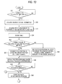
- the procedure of processing for generating the past program table 44, which procedure is executed by the past program table generating module 50, will be described with reference to Fig. 10 .
- Fig. 10 is a flow chart showing the procedure to display the past program table 44 at the beginning of playback based on the second playback method, which procedure is executed by the past program table generating module 50 in this embodiment.
- the past program table generating module 50 determines whether an instruction has been received from the time shift key 150k or not (Step S31). When the determination in Step S31 results in that no instruction has been received from the time shift key 150k (No in Step S31), the procedure returns to Step S31.
- Step S31 when the determination in Step S31 results in that an instruction has been received from the time shift key 150k (Yes in Step S31), the past program table generating module 50 then receives channel information of a channel being currently viewed, from the signal processing module 12 (Step S32).
- the past program table generating module 50 acquires EPG information from TSs 43 of channels recorded by the second recording method (Step S33). That is, EPG information is acquired from each TS 43 stored in the second recording area 172.
- the past program table generating module 50 generates a table 46 based on the channel information acquired in Step S33 (Step S34). That is, a table 46 where program information is displayed in each column with the ordinate set as the recording time indicator 47 and the abscissa set as the channel indicator 48.
- the past program table generating module 50 determines whether the currently viewed channel is a channel recorded by the second recording method or not (Step S35).
- the position of the focus 45 is decided as the latest recorded program of a channel whose channel number is the smallest of the channels recorded by the second recording method (Step S36). Channels are displayed in channel number order by the channel indicator 48 in the past program table 44. Therefore, the position of the focus 45 decided in Step S36 is an end space of the table 46.
- Step S35 when the determination in Step S35 results in that the channel is a channel recorded by the second recording method (Yes in Step S35), the position of the focus is decided as the latest recorded program of the channel which is being viewed (Step S37).
- the past program table generating module 50 displays the past program table 44 where the table 46 decided in Step S34 and the focus 45 decided in Step S36 or S37 are superimposed on each other (Step S38).
- the past program table generating module 50 determines whether a program to be played back has been designated from the past program table 44 or not (Step S39). That is, determination is made as to whether the focus 45 has been moved onto a desired recorded program and the decide key 150g has been pushed down or not.
- Step S39 When the determination in Step S39 results in that no program to be played back has been designated (No in Step S39), the procedure returns to Step S39. On the contrary, when the determination in Step S39 results in that a program to be played back has been designated (Yes in Step S39), playback of the designated recorded program is started. Then, the procedure advances to Step S41 shown in Fig. 11 .
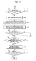
- Fig. 11 is a flow chart showing the procedure of displaying the past program table 44 during playback based on the second playback method, which procedure is executed by the past program table generating module 50 in this embodiment.
- the past program table generating module 50 determines whether an instruction has been received from the program table key 1501 or not (Step S41). When the determination in Step S41 result in that no instruction has been received from the program table key 1501 (No in Step S41), the procedure returns to Step S41. On the contrary, when the determination results in that an instruction has been received from the program table key 1501 (Yes in Step S41), the past program table generating module 50 acquires a playback position of a TS 43 which is being played back by the recording/playback control method 22 (Step S42).
- the past program table generating module 50 decides the position of the focus 45 as a position corresponding to the playback position acquired in Step S42 (Step S43).
- the past program table generating module 50 displays the past program table 44 where the table 46 and the focus 45 decided in Step S43 are superimposed on each other (Step S44).
- the past program table generating module 50 determines whether a program to be played back has been designated from the past program table 44 displayed in Step S44 or not (Step S45).
- the procedure returns to the aforementioned Step S40.
- the past program table generating module 50 determines whether an instruction to terminate the display of the past program table 44 has been received or not (Step S46). Assume that the instruction to terminate the display of the past program table 44 is executed, for example, by pushing down the program table key 1501 again.
- Step S46 When the determination in Step S46 results in that the instruction to terminate the display of the past program table 44 has not been received (No in Step S46), the procedure returns to Step S46. On the contrary, when the determination in Step S46 results in that the instruction to terminate the display of the past program table 44 has been received (Yes in Step 46), the program which was being played back is displayed again (Step S47). That is, playback is resumed at the playback position acquired in Step S42.
- the past program table generating module 50 determines whether an instruction to terminate the playback based on the second playback method has been received or not (Step S48).
- the procedure returns to Step S48.
- the determination in Step S48 results in that the instruction to terminate the playback has been received (Yes in Step S48)
- the playback based on the second playback method is terminated.
- the instruction to terminate the playback for example, means that an instruction to escape from the time shift mode is given by the time shift key 150k, the stop button or the like.
- a program being played back can be displayed more exactly in the past program table 44 when the playback is being carried out by the second playback method.
- a program being played back can be indicated specifically in the past program table 44 by use of the focus 45.
- a channel being played back can be switched to another channel recorded in the same time as the playback time of the channel being played back.
- the channel can be switched to view a program retrospectively as if broadcasting of the program were viewed in real time.
- recorded programs can be played back in a different view point from that in the related art, and a novel method for searching an increasing number of recorded programs for a program to be viewed can be provided.
- the past program table 44 can be displayed by the past program table generating module 50 in this embodiment. Thus, to which channel the channel has moved can be grasped easily.
- the invention is not limited to the aforementioned embodiment per se and constituent members may be changed or modified for embodying the invention without departing from the gist of the invention in a practical stage.
- Constituent members disclosed in the aforementioned embodiment may be combined suitably to form various inventions. For example, some of all constituent members disclosed in the embodiment may be removed. In addition, constituent members disclosed in different embodiments may be combined suitably.
Landscapes
- Engineering & Computer Science (AREA)
- Multimedia (AREA)
- Signal Processing (AREA)
- Human Computer Interaction (AREA)
- Databases & Information Systems (AREA)
- Television Signal Processing For Recording (AREA)
- Two-Way Televisions, Distribution Of Moving Picture Or The Like (AREA)
Applications Claiming Priority (1)
| Application Number | Priority Date | Filing Date | Title |
|---|---|---|---|
| JP2009218567A JP4686628B2 (ja) | 2009-09-24 | 2009-09-24 | 電子機器及び番組表表示方法 |
Publications (3)
| Publication Number | Publication Date |
|---|---|
| EP2302899A2 true EP2302899A2 (de) | 2011-03-30 |
| EP2302899A3 EP2302899A3 (de) | 2015-09-23 |
| EP2302899B1 EP2302899B1 (de) | 2019-10-09 |
Family
ID=43479403
Family Applications (1)
| Application Number | Title | Priority Date | Filing Date |
|---|---|---|---|
| EP10172345.0A Active EP2302899B1 (de) | 2009-09-24 | 2010-08-10 | Elektronische Vorrichtung und Programmtabellenanzeigeverfahren |
Country Status (2)
| Country | Link |
|---|---|
| EP (1) | EP2302899B1 (de) |
| JP (1) | JP4686628B2 (de) |
Cited By (1)
| Publication number | Priority date | Publication date | Assignee | Title |
|---|---|---|---|---|
| CN109168035A (zh) * | 2018-09-17 | 2019-01-08 | 北京数码视讯科技股份有限公司 | 一种epg信息控制装置 |
Families Citing this family (1)
| Publication number | Priority date | Publication date | Assignee | Title |
|---|---|---|---|---|
| JP2012222800A (ja) * | 2011-04-14 | 2012-11-12 | Toshiba Corp | 放送受信装置および放送受信装置の制御方法 |
Citations (1)
| Publication number | Priority date | Publication date | Assignee | Title |
|---|---|---|---|---|
| JPH11112899A (ja) | 1997-09-30 | 1999-04-23 | Matsushita Electric Ind Co Ltd | ディジタル放送受信装置 |
Family Cites Families (8)
| Publication number | Priority date | Publication date | Assignee | Title |
|---|---|---|---|---|
| JP4953496B2 (ja) * | 2000-05-15 | 2012-06-13 | ソニー株式会社 | コンテンツ検索・提示システム及び方法、並びに、ソフトウェア記憶媒体 |
| JP4139592B2 (ja) * | 2001-12-27 | 2008-08-27 | 旭ファイバーグラス株式会社 | 断熱工法選択支援システム |
| KR100793801B1 (ko) * | 2006-07-06 | 2008-01-11 | 엘지전자 주식회사 | 티브이의 방송 프로그램 안내 표시 방법 및 장치 |
| JP2008035218A (ja) * | 2006-07-28 | 2008-02-14 | Funai Electric Co Ltd | 記録再生装置および自動録画方法 |
| JP2008182539A (ja) * | 2007-01-25 | 2008-08-07 | Victor Co Of Japan Ltd | 放送受信記録再生装置および放送受信記録再生方法 |
| JP2008278222A (ja) * | 2007-04-27 | 2008-11-13 | Toshiba Corp | テレビジョン受信装置 |
| JP5153311B2 (ja) * | 2007-12-18 | 2013-02-27 | 三菱電機株式会社 | 放送番組視聴システム |
| JP4958922B2 (ja) * | 2009-01-23 | 2012-06-20 | キヤノン株式会社 | 情報処理装置及びその制御方法 |
-
2009
- 2009-09-24 JP JP2009218567A patent/JP4686628B2/ja active Active
-
2010
- 2010-08-10 EP EP10172345.0A patent/EP2302899B1/de active Active
Patent Citations (1)
| Publication number | Priority date | Publication date | Assignee | Title |
|---|---|---|---|---|
| JPH11112899A (ja) | 1997-09-30 | 1999-04-23 | Matsushita Electric Ind Co Ltd | ディジタル放送受信装置 |
Cited By (2)
| Publication number | Priority date | Publication date | Assignee | Title |
|---|---|---|---|---|
| CN109168035A (zh) * | 2018-09-17 | 2019-01-08 | 北京数码视讯科技股份有限公司 | 一种epg信息控制装置 |
| CN109168035B (zh) * | 2018-09-17 | 2020-11-17 | 北京数码视讯科技股份有限公司 | 一种epg信息控制装置 |
Also Published As
| Publication number | Publication date |
|---|---|
| EP2302899A3 (de) | 2015-09-23 |
| JP4686628B2 (ja) | 2011-05-25 |
| EP2302899B1 (de) | 2019-10-09 |
| JP2011071586A (ja) | 2011-04-07 |
Similar Documents
| Publication | Publication Date | Title |
|---|---|---|
| EP1788805A2 (de) | Zeitschiebe-Wiedergabefunktionsausführungsverfahren und dieses Verfahren benutzendes Fernsehempfangsgerät. | |
| EP2056595B1 (de) | Verfahren zur Bereitstellung der Liste und Unterliste mit Multimedia-Inhalt und Rundfunkempfangsvorrichtung damit | |
| KR101391752B1 (ko) | 영상처리장치 및 그 제어방법 | |
| JP4937415B2 (ja) | 電子機器および番組表作成方法 | |
| JP2007251803A (ja) | 記録再生装置、携帯端末装置、記録再生システム、及び記録再生方法 | |
| US8782522B2 (en) | Video display device and menu screen display method | |
| JP2010176786A (ja) | コントローラ、録画機器及びメニュー表示方法 | |
| EP2302899B1 (de) | Elektronische Vorrichtung und Programmtabellenanzeigeverfahren | |
| US20060232707A1 (en) | Broadcast receiver and broadcast receiving method | |
| KR100757768B1 (ko) | 방송 프로그램 정보 표시 장치 및 방송 프로그램 정보 표시방법 | |
| JP4635098B1 (ja) | 電子機器 | |
| JP5016729B2 (ja) | 表示装置 | |
| EP2302910A1 (de) | Elektronische Vorrichtung und Anzeigeverfahren | |
| EP2373010B1 (de) | Elektronische Vorrichtung und aufgezeichnetes Programmanzeigeverfahren | |
| JP4818471B2 (ja) | 電子機器 | |
| US20090052865A1 (en) | Broadcast receiver and broadcast receiving method | |
| US20060080705A1 (en) | Broadcast receiver, video signal output apparatus and broadcast receiving method | |
| JP2006074614A (ja) | 放送受信装置 | |
| US20080025693A1 (en) | Method and apparatus for recording and reproducing broadcasting program | |
| EP2530931A2 (de) | Aufzeichnungs- und Wiedergabevorrichtung und Aufzeichnungs- und Wiedergabeverfahren | |
| JP2011217188A (ja) | 放送受信装置及び表示制御方法 | |
| US20070277206A1 (en) | Reproduction control device and method for image display apparatus | |
| JP2006094210A (ja) | 放送受信装置 | |
| US8478112B2 (en) | Digital broadcast recording device | |
| JP6113438B2 (ja) | データ管理装置及び方法及びテレビジョン受信装置 |
Legal Events
| Date | Code | Title | Description |
|---|---|---|---|
| PUAI | Public reference made under article 153(3) epc to a published international application that has entered the european phase |
Free format text: ORIGINAL CODE: 0009012 |
|
| 17P | Request for examination filed |
Effective date: 20100810 |
|
| AK | Designated contracting states |
Kind code of ref document: A2 Designated state(s): AL AT BE BG CH CY CZ DE DK EE ES FI FR GB GR HR HU IE IS IT LI LT LU LV MC MK MT NL NO PL PT RO SE SI SK SM TR |
|
| AX | Request for extension of the european patent |
Extension state: BA ME RS |
|
| PUAL | Search report despatched |
Free format text: ORIGINAL CODE: 0009013 |
|
| AK | Designated contracting states |
Kind code of ref document: A3 Designated state(s): AL AT BE BG CH CY CZ DE DK EE ES FI FR GB GR HR HU IE IS IT LI LT LU LV MC MK MT NL NO PL PT RO SE SI SK SM TR |
|
| AX | Request for extension of the european patent |
Extension state: BA ME RS |
|
| RIC1 | Information provided on ipc code assigned before grant |
Ipc: H04N 5/00 20110101AFI20150814BHEP Ipc: H04N 21/482 20110101ALI20150814BHEP Ipc: H04N 21/433 20110101ALI20150814BHEP |
|
| 17Q | First examination report despatched |
Effective date: 20160720 |
|
| STAA | Information on the status of an ep patent application or granted ep patent |
Free format text: STATUS: EXAMINATION IS IN PROGRESS |
|
| RAP1 | Party data changed (applicant data changed or rights of an application transferred) |
Owner name: TOSHIBA VISUAL SOLUTIONS CORPORATION Owner name: KABUSHIKI KAISHA TOSHIBA |
|
| RAP1 | Party data changed (applicant data changed or rights of an application transferred) |
Owner name: TOSHIBA VISUAL SOLUTIONS CORPORATION |
|
| GRAP | Despatch of communication of intention to grant a patent |
Free format text: ORIGINAL CODE: EPIDOSNIGR1 |
|
| STAA | Information on the status of an ep patent application or granted ep patent |
Free format text: STATUS: GRANT OF PATENT IS INTENDED |
|
| INTG | Intention to grant announced |
Effective date: 20190325 |
|
| GRAS | Grant fee paid |
Free format text: ORIGINAL CODE: EPIDOSNIGR3 |
|
| RAP1 | Party data changed (applicant data changed or rights of an application transferred) |
Owner name: TOSHIBA VISUAL SOLUTIONS CORPORATION Owner name: QINGDAO HISENSE ELECTRONICS CO., LTD. |
|
| GRAA | (expected) grant |
Free format text: ORIGINAL CODE: 0009210 |
|
| STAA | Information on the status of an ep patent application or granted ep patent |
Free format text: STATUS: THE PATENT HAS BEEN GRANTED |
|
| AK | Designated contracting states |
Kind code of ref document: B1 Designated state(s): AL AT BE BG CH CY CZ DE DK EE ES FI FR GB GR HR HU IE IS IT LI LT LU LV MC MK MT NL NO PL PT RO SE SI SK SM TR |
|
| REG | Reference to a national code |
Ref country code: GB Ref legal event code: FG4D |
|
| REG | Reference to a national code |
Ref country code: CH Ref legal event code: EP |
|
| REG | Reference to a national code |
Ref country code: IE Ref legal event code: FG4D |
|
| REG | Reference to a national code |
Ref country code: DE Ref legal event code: R096 Ref document number: 602010061411 Country of ref document: DE |
|
| REG | Reference to a national code |
Ref country code: AT Ref legal event code: REF Ref document number: 1190189 Country of ref document: AT Kind code of ref document: T Effective date: 20191115 |
|
| REG | Reference to a national code |
Ref country code: NL Ref legal event code: MP Effective date: 20191009 |
|
| REG | Reference to a national code |
Ref country code: LT Ref legal event code: MG4D |
|
| REG | Reference to a national code |
Ref country code: AT Ref legal event code: MK05 Ref document number: 1190189 Country of ref document: AT Kind code of ref document: T Effective date: 20191009 |
|
| PG25 | Lapsed in a contracting state [announced via postgrant information from national office to epo] |
Ref country code: FI Free format text: LAPSE BECAUSE OF FAILURE TO SUBMIT A TRANSLATION OF THE DESCRIPTION OR TO PAY THE FEE WITHIN THE PRESCRIBED TIME-LIMIT Effective date: 20191009 Ref country code: NO Free format text: LAPSE BECAUSE OF FAILURE TO SUBMIT A TRANSLATION OF THE DESCRIPTION OR TO PAY THE FEE WITHIN THE PRESCRIBED TIME-LIMIT Effective date: 20200109 Ref country code: BG Free format text: LAPSE BECAUSE OF FAILURE TO SUBMIT A TRANSLATION OF THE DESCRIPTION OR TO PAY THE FEE WITHIN THE PRESCRIBED TIME-LIMIT Effective date: 20200109 Ref country code: LT Free format text: LAPSE BECAUSE OF FAILURE TO SUBMIT A TRANSLATION OF THE DESCRIPTION OR TO PAY THE FEE WITHIN THE PRESCRIBED TIME-LIMIT Effective date: 20191009 Ref country code: PL Free format text: LAPSE BECAUSE OF FAILURE TO SUBMIT A TRANSLATION OF THE DESCRIPTION OR TO PAY THE FEE WITHIN THE PRESCRIBED TIME-LIMIT Effective date: 20191009 Ref country code: NL Free format text: LAPSE BECAUSE OF FAILURE TO SUBMIT A TRANSLATION OF THE DESCRIPTION OR TO PAY THE FEE WITHIN THE PRESCRIBED TIME-LIMIT Effective date: 20191009 Ref country code: AT Free format text: LAPSE BECAUSE OF FAILURE TO SUBMIT A TRANSLATION OF THE DESCRIPTION OR TO PAY THE FEE WITHIN THE PRESCRIBED TIME-LIMIT Effective date: 20191009 Ref country code: PT Free format text: LAPSE BECAUSE OF FAILURE TO SUBMIT A TRANSLATION OF THE DESCRIPTION OR TO PAY THE FEE WITHIN THE PRESCRIBED TIME-LIMIT Effective date: 20200210 Ref country code: GR Free format text: LAPSE BECAUSE OF FAILURE TO SUBMIT A TRANSLATION OF THE DESCRIPTION OR TO PAY THE FEE WITHIN THE PRESCRIBED TIME-LIMIT Effective date: 20200110 Ref country code: ES Free format text: LAPSE BECAUSE OF FAILURE TO SUBMIT A TRANSLATION OF THE DESCRIPTION OR TO PAY THE FEE WITHIN THE PRESCRIBED TIME-LIMIT Effective date: 20191009 Ref country code: LV Free format text: LAPSE BECAUSE OF FAILURE TO SUBMIT A TRANSLATION OF THE DESCRIPTION OR TO PAY THE FEE WITHIN THE PRESCRIBED TIME-LIMIT Effective date: 20191009 Ref country code: SE Free format text: LAPSE BECAUSE OF FAILURE TO SUBMIT A TRANSLATION OF THE DESCRIPTION OR TO PAY THE FEE WITHIN THE PRESCRIBED TIME-LIMIT Effective date: 20191009 |
|
| PG25 | Lapsed in a contracting state [announced via postgrant information from national office to epo] |
Ref country code: HR Free format text: LAPSE BECAUSE OF FAILURE TO SUBMIT A TRANSLATION OF THE DESCRIPTION OR TO PAY THE FEE WITHIN THE PRESCRIBED TIME-LIMIT Effective date: 20191009 Ref country code: IS Free format text: LAPSE BECAUSE OF FAILURE TO SUBMIT A TRANSLATION OF THE DESCRIPTION OR TO PAY THE FEE WITHIN THE PRESCRIBED TIME-LIMIT Effective date: 20200224 |
|
| PG25 | Lapsed in a contracting state [announced via postgrant information from national office to epo] |
Ref country code: AL Free format text: LAPSE BECAUSE OF FAILURE TO SUBMIT A TRANSLATION OF THE DESCRIPTION OR TO PAY THE FEE WITHIN THE PRESCRIBED TIME-LIMIT Effective date: 20191009 |
|
| REG | Reference to a national code |
Ref country code: DE Ref legal event code: R097 Ref document number: 602010061411 Country of ref document: DE |
|
| PG2D | Information on lapse in contracting state deleted |
Ref country code: IS |
|
| PG25 | Lapsed in a contracting state [announced via postgrant information from national office to epo] |
Ref country code: RO Free format text: LAPSE BECAUSE OF FAILURE TO SUBMIT A TRANSLATION OF THE DESCRIPTION OR TO PAY THE FEE WITHIN THE PRESCRIBED TIME-LIMIT Effective date: 20191009 Ref country code: CZ Free format text: LAPSE BECAUSE OF FAILURE TO SUBMIT A TRANSLATION OF THE DESCRIPTION OR TO PAY THE FEE WITHIN THE PRESCRIBED TIME-LIMIT Effective date: 20191009 Ref country code: DK Free format text: LAPSE BECAUSE OF FAILURE TO SUBMIT A TRANSLATION OF THE DESCRIPTION OR TO PAY THE FEE WITHIN THE PRESCRIBED TIME-LIMIT Effective date: 20191009 Ref country code: EE Free format text: LAPSE BECAUSE OF FAILURE TO SUBMIT A TRANSLATION OF THE DESCRIPTION OR TO PAY THE FEE WITHIN THE PRESCRIBED TIME-LIMIT Effective date: 20191009 Ref country code: IS Free format text: LAPSE BECAUSE OF FAILURE TO SUBMIT A TRANSLATION OF THE DESCRIPTION OR TO PAY THE FEE WITHIN THE PRESCRIBED TIME-LIMIT Effective date: 20200209 |
|
| PLBE | No opposition filed within time limit |
Free format text: ORIGINAL CODE: 0009261 |
|
| STAA | Information on the status of an ep patent application or granted ep patent |
Free format text: STATUS: NO OPPOSITION FILED WITHIN TIME LIMIT |
|
| REG | Reference to a national code |
Ref country code: DE Ref legal event code: R082 Ref document number: 602010061411 Country of ref document: DE Representative=s name: PFENNING, MEINIG & PARTNER MBB PATENTANWAELTE, DE Ref country code: DE Ref legal event code: R081 Ref document number: 602010061411 Country of ref document: DE Owner name: HLSENSE VISUAL TECHNOLOGY CO., LTD., SHANDONG, CN Free format text: FORMER OWNERS: QINGDAO HISENSE ELECTRONICS CO., LTD., SHANDONG, QINGDAO, CN; TOSHIBA VISUAL SOLUTIONS CORP., MISAWA-SHI, AOMORI, JP Ref country code: DE Ref legal event code: R081 Ref document number: 602010061411 Country of ref document: DE Owner name: TOSHIBA VISUAL SOLUTIONS CORP., MISAWA-SHI, JP Free format text: FORMER OWNERS: QINGDAO HISENSE ELECTRONICS CO., LTD., SHANDONG, QINGDAO, CN; TOSHIBA VISUAL SOLUTIONS CORP., MISAWA-SHI, AOMORI, JP |
|
| PG25 | Lapsed in a contracting state [announced via postgrant information from national office to epo] |
Ref country code: SK Free format text: LAPSE BECAUSE OF FAILURE TO SUBMIT A TRANSLATION OF THE DESCRIPTION OR TO PAY THE FEE WITHIN THE PRESCRIBED TIME-LIMIT Effective date: 20191009 Ref country code: SM Free format text: LAPSE BECAUSE OF FAILURE TO SUBMIT A TRANSLATION OF THE DESCRIPTION OR TO PAY THE FEE WITHIN THE PRESCRIBED TIME-LIMIT Effective date: 20191009 Ref country code: IT Free format text: LAPSE BECAUSE OF FAILURE TO SUBMIT A TRANSLATION OF THE DESCRIPTION OR TO PAY THE FEE WITHIN THE PRESCRIBED TIME-LIMIT Effective date: 20191009 |
|
| 26N | No opposition filed |
Effective date: 20200710 |
|
| PG25 | Lapsed in a contracting state [announced via postgrant information from national office to epo] |
Ref country code: SI Free format text: LAPSE BECAUSE OF FAILURE TO SUBMIT A TRANSLATION OF THE DESCRIPTION OR TO PAY THE FEE WITHIN THE PRESCRIBED TIME-LIMIT Effective date: 20191009 |
|
| PG25 | Lapsed in a contracting state [announced via postgrant information from national office to epo] |
Ref country code: MC Free format text: LAPSE BECAUSE OF FAILURE TO SUBMIT A TRANSLATION OF THE DESCRIPTION OR TO PAY THE FEE WITHIN THE PRESCRIBED TIME-LIMIT Effective date: 20191009 |
|
| REG | Reference to a national code |
Ref country code: CH Ref legal event code: PL |
|
| PG25 | Lapsed in a contracting state [announced via postgrant information from national office to epo] |
Ref country code: LU Free format text: LAPSE BECAUSE OF NON-PAYMENT OF DUE FEES Effective date: 20200810 Ref country code: LI Free format text: LAPSE BECAUSE OF NON-PAYMENT OF DUE FEES Effective date: 20200831 Ref country code: CH Free format text: LAPSE BECAUSE OF NON-PAYMENT OF DUE FEES Effective date: 20200831 |
|
| REG | Reference to a national code |
Ref country code: BE Ref legal event code: MM Effective date: 20200831 |
|
| PG25 | Lapsed in a contracting state [announced via postgrant information from national office to epo] |
Ref country code: IE Free format text: LAPSE BECAUSE OF NON-PAYMENT OF DUE FEES Effective date: 20200810 Ref country code: BE Free format text: LAPSE BECAUSE OF NON-PAYMENT OF DUE FEES Effective date: 20200831 |
|
| PG25 | Lapsed in a contracting state [announced via postgrant information from national office to epo] |
Ref country code: TR Free format text: LAPSE BECAUSE OF FAILURE TO SUBMIT A TRANSLATION OF THE DESCRIPTION OR TO PAY THE FEE WITHIN THE PRESCRIBED TIME-LIMIT Effective date: 20191009 Ref country code: MT Free format text: LAPSE BECAUSE OF FAILURE TO SUBMIT A TRANSLATION OF THE DESCRIPTION OR TO PAY THE FEE WITHIN THE PRESCRIBED TIME-LIMIT Effective date: 20191009 Ref country code: CY Free format text: LAPSE BECAUSE OF FAILURE TO SUBMIT A TRANSLATION OF THE DESCRIPTION OR TO PAY THE FEE WITHIN THE PRESCRIBED TIME-LIMIT Effective date: 20191009 |
|
| PG25 | Lapsed in a contracting state [announced via postgrant information from national office to epo] |
Ref country code: MK Free format text: LAPSE BECAUSE OF FAILURE TO SUBMIT A TRANSLATION OF THE DESCRIPTION OR TO PAY THE FEE WITHIN THE PRESCRIBED TIME-LIMIT Effective date: 20191009 |
|
| P01 | Opt-out of the competence of the unified patent court (upc) registered |
Effective date: 20230511 |
|
| PGFP | Annual fee paid to national office [announced via postgrant information from national office to epo] |
Ref country code: DE Payment date: 20250820 Year of fee payment: 16 |
|
| PGFP | Annual fee paid to national office [announced via postgrant information from national office to epo] |
Ref country code: GB Payment date: 20250820 Year of fee payment: 16 |
|
| PGFP | Annual fee paid to national office [announced via postgrant information from national office to epo] |
Ref country code: FR Payment date: 20250829 Year of fee payment: 16 |