EP2299217B1 - Compartiment de rangement pour un appareil frigorifique - Google Patents
Compartiment de rangement pour un appareil frigorifique Download PDFInfo
- Publication number
- EP2299217B1 EP2299217B1 EP10173646.0A EP10173646A EP2299217B1 EP 2299217 B1 EP2299217 B1 EP 2299217B1 EP 10173646 A EP10173646 A EP 10173646A EP 2299217 B1 EP2299217 B1 EP 2299217B1
- Authority
- EP
- European Patent Office
- Prior art keywords
- flap
- box
- storage compartment
- compartment according
- pivot axis
- Prior art date
- Legal status (The legal status is an assumption and is not a legal conclusion. Google has not performed a legal analysis and makes no representation as to the accuracy of the status listed.)
- Active
Links
- 238000001816 cooling Methods 0.000 title description 2
- 235000014121 butter Nutrition 0.000 claims description 15
- 238000005057 refrigeration Methods 0.000 claims description 5
- 230000000717 retained effect Effects 0.000 claims 1
- 230000005484 gravity Effects 0.000 description 4
- 239000002775 capsule Substances 0.000 description 2
- 230000000694 effects Effects 0.000 description 2
- 238000010276 construction Methods 0.000 description 1
- 230000001934 delay Effects 0.000 description 1
- 239000012530 fluid Substances 0.000 description 1
- 239000007788 liquid Substances 0.000 description 1
- 230000000630 rising effect Effects 0.000 description 1
- 230000006641 stabilisation Effects 0.000 description 1
- 238000011105 stabilization Methods 0.000 description 1
Images

Classifications
-
- F—MECHANICAL ENGINEERING; LIGHTING; HEATING; WEAPONS; BLASTING
- F25—REFRIGERATION OR COOLING; COMBINED HEATING AND REFRIGERATION SYSTEMS; HEAT PUMP SYSTEMS; MANUFACTURE OR STORAGE OF ICE; LIQUEFACTION SOLIDIFICATION OF GASES
- F25D—REFRIGERATORS; COLD ROOMS; ICE-BOXES; COOLING OR FREEZING APPARATUS NOT OTHERWISE PROVIDED FOR
- F25D23/00—General constructional features
- F25D23/02—Doors; Covers
- F25D23/04—Doors; Covers with special compartments, e.g. butter conditioners
-
- F—MECHANICAL ENGINEERING; LIGHTING; HEATING; WEAPONS; BLASTING
- F25—REFRIGERATION OR COOLING; COMBINED HEATING AND REFRIGERATION SYSTEMS; HEAT PUMP SYSTEMS; MANUFACTURE OR STORAGE OF ICE; LIQUEFACTION SOLIDIFICATION OF GASES
- F25D—REFRIGERATORS; COLD ROOMS; ICE-BOXES; COOLING OR FREEZING APPARATUS NOT OTHERWISE PROVIDED FOR
- F25D23/00—General constructional features
- F25D23/02—Doors; Covers
- F25D23/025—Secondary closures
-
- F—MECHANICAL ENGINEERING; LIGHTING; HEATING; WEAPONS; BLASTING
- F25—REFRIGERATION OR COOLING; COMBINED HEATING AND REFRIGERATION SYSTEMS; HEAT PUMP SYSTEMS; MANUFACTURE OR STORAGE OF ICE; LIQUEFACTION SOLIDIFICATION OF GASES
- F25D—REFRIGERATORS; COLD ROOMS; ICE-BOXES; COOLING OR FREEZING APPARATUS NOT OTHERWISE PROVIDED FOR
- F25D23/00—General constructional features
- F25D23/12—Arrangements of compartments additional to cooling compartments; Combinations of refrigerators with other equipment, e.g. stove
- F25D23/123—Butter compartment
Definitions
- the present invention relates to a storage compartment, in particular a door storage compartment, such as a butter compartment, for a refrigeration appliance, in particular a household refrigerating appliance, i. a container which is separable from the remaining interior of the refrigerator to store refrigerated goods at another, usually slightly higher temperature than the rest of the interior can.
- a refrigeration appliance in particular a household refrigerating appliance, i. a container which is separable from the remaining interior of the refrigerator to store refrigerated goods at another, usually slightly higher temperature than the rest of the interior can.
- a butter compartment is normally mounted on the inside of a door of a refrigerator near its upper edge.
- the butter compartment is closed by a flap that pivots upward to open about a horizontal axis. If one would close the door with the flap swung open in such a refrigeration device, the flap would abut against the body of the refrigeration device and break off. To avoid this, the flap usually does not have a stable raised position, but falls immediately when released. A user who wants to access the contents of the butter compartment therefore always needs a hand to hold the flap open.
- US 2006/0290144 A1 discloses a door opening closing device having a rotating mechanism configured to adjust the door between a closed position and an open position relative to a base member.
- the rotary mechanism has a support arm integrally formed with the door, a sector gear portion provided on the arm, a rotary gear supported on the support arm, a first rack portion, and a second rack portion provided on the base member.
- US 1,115,135 discloses a container with a door that is openable and closable.
- the door can be pivoted to open from a vertical to a horizontal position.
- German patent application no. 10 2008 026 381.8 (see also EP-A-2 131 125 ) describes a door storage compartment having a box and a flap which is movable between a closed position in front of an open front of the box and an open position in which it is recessed in a space between two bottom plates of the box.
- Object of the present invention is a storage compartment, in particular a door storage compartment for a refrigerator, to provide a box and a movable flap, wherein the flap after it has been deflected by the user from its closed position, reliably reaches an open position automatically.
- the object is achieved by providing a storage compartment, in particular a door storage compartment, with a box and a flap movable between a closed position in front of an open front of the box and an open position at least partially overlapping with a bottom panel of the box, wherein a first pivot axis (17; ) of the flap (2) on the box (1) in the depth direction on a first guide track (9; 10) is displaceable, at least one connecting the flap with the box spring element is provided, which is more tensioned in the closed position than in the open position ,
- the relaxation of the spring element drives the movement of the flap targeted until it reaches the Open position.
- the path runs or run the tracks in a space between two floor panels or between two ceiling panels of the box.
- the flap overlaps in its open position with the bottom plate of the box largely, especially completely.
- At least a first pivot axis of the flap preferably even two pivot axes guided in the depth direction on a first and second guide rail slidably.
- This web or these webs expediently run below a base plate or above a ceiling plate of the box, so that the movement of the flap can not be blocked by refrigerated goods contained in the box.
- Below the base plate or above the ceiling plate is also the height level of the two plates to understand.
- the tracks are formed as guide grooves on a side wall of the box, and the pivot axes are defined by pins of the flap, which engage in these guide grooves.
- the spring element may suitably attack on one of these pins.
- the spring element is conveniently housed protected in a cavity of the side wall.
- the pin on which the spring element engages can protrude through its guide groove into the cavity.
- the guide grooves leading the first and second pivot axes, respectively diverge vertically toward the front of the box.
- the spring element can contribute to the stabilization of the flap in the closed position by keeping the first pivot axis pressed against one end of the first guide groove in this closed position.
- the spring element expediently has an arm pivotable about an axis and engaging the flap.
- this arm expediently acts on the second pivot axis.
- this second pivot axis is closer to the axis of the arm than the first pivot axis.
- a damper may be provided which delays the flap before reaching the open position.
- a rotary damper in particular a rotary damper can be used, which is coupled via an arm pivotable about an axis of the flap.
- this arm may be the same arm that also engages the second pivot axis.
- the spring element connecting the flap with the box is preferably provided twice, once on each side wall of the box.
- the invention is conceivable in addition to a door storage compartment also on a storage compartment arranged in the cooling space of a refrigerator or freezer, for example under a refrigerated goods deposit.
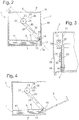
- Fig. 1 Butter compartment shown comprises a substantially cuboid box 1, which is intended to be mounted on the inside of a refrigerator door, not shown, and provided for pivotally mounting on the box 1 flap second
- Fastening means such as locking recesses or projections on hollow in this case formed side walls 3 of the box for hanging on vertical bars of the refrigerator door are known in the art and for clarity in Fig. 1 not shown.
- a vertical rear wall 4 Between the side walls 3 extend a vertical rear wall 4, a ceiling plate 5, and an upper and a lower bottom plate 6, 7. Front edges of the bottom plates 6, 7 extend to near leading edges of the side walls 3; a front edge of the ceiling plate 5 is slightly more set back than the front edges of the bottom plates 6, 7 and centrally provided with an engagement recess 8.
- an upper groove 9 and a lower groove 10 are recessed respectively.
- Both grooves 9, 10 extend over a large part of their length in a gap 11 delimited by the bottom plates 6, 7, rising slightly towards the open front side of the box 1 and, in the present case, open to the internal cavity of the side walls 3.
- the upper groove 9 terminates with an approximately quarter-circular upwardly curved portion 12.
- a downwardly curved portion 13 at the front end of the lower groove 10 has a substantially smaller radius of curvature than the portion 12th
- the flap 2 has substantially the shape of an inverted L-profile with a front panel 15 covering the front of the box 1 and an angled from the upper edge of the front panel 15 web 16. From a lower edge of the front panel 15 are pins 17 in opposite directions laterally. Another pair of laterally projecting pins 18 is formed on at the front plate 15 rearwardly projecting tabs 19.
- the pins 17 are provided to engage in the lower grooves 10 and to define a first pivot axis of the cap 2; the pins 18 form a second pivot axis by engaging in the upper grooves 9.
- the pins 18 extend through the grooves 9 through into the inner cavity of the side walls 3.
- the front panel 15 covers the open front of the box 1, and the web 16 abuts both sides of the engagement recess 8 at the front edge of the ceiling plate 5 at.
- This condition is in Fig. 2 shown in section.
- the pins 17 are located at a locally lowest point at the front end of the lower grooves 10, while the pins 18 from the front upper end of the grooves 9 are a distance away. This locally lowest point defines a kind of detent position for the flap 2 in the closed state.
- Fig. 3 shows a section through a side wall 3 along the in Fig. 2 Level III-III.
- the other side wall 3 is equal to the mirror image shown.
- the side wall 3 comprises an outer plate 20 and an inner plate 21, in which the grooves 9, 10 extend. At least the upper groove 9 is formed as a slot open to an inner cavity 22 of the side wall 3.
- a roller 23 is rotatably mounted on a projecting from the inner plate 21 bearing pin 24.
- the roller 23 is wrapped by a torsionally loaded leg spring 25 with two tangentially projecting arms 26, 27.
- One of the arms, designated 26, abuts against a second pin 28 protruding from the inner plate 21, the second arm 27 presses against a projection 30 of a from the roller 23 radially projecting and rotatable with this rigid arm 29 and exerts on this torque in a clockwise direction.
- the pin 18 engages through the groove 9 in a radially oriented open-edged slot 31 of the arm 29 a.
- Fig. 4 shows a section through the storage compartment with the flap 2 in partially open position.
- the flap 2 is already pivoted by an angle of more than 60 ° in the direction of the horizontal, but is still largely out of the box 1, but the pins are still in the quarter-circle-shaped front portion of the groove 9, and the Arm 29 is only slightly compared to the position of Fig. 2 pivoted clockwise. He therefore only slightly supports the initial pivotal movement of the flap 2; In order to drive these after overcoming the initial resistance, essentially enough to the effect of gravity.
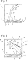
- a (not shown) elastic buffer may be mounted in the gap 11 on the rear wall 4 to a hard, noisy striking the flap 2 upon reaching the open position of the Fig. 5 to avoid.
- a gap 40 is present in the open position, which makes it easier for the user to grab the flap 2 at its web 16, to pull out of the gap 11 and into the closed position of the Fig. 2 to swing back.
- the torsion springs 25 are tightened again.
- Fig. 6 shows you one Fig. 2 analog section according to a second embodiment of the invention.
- a rigid arm 29 is rotatably supported about a projecting from the inner plate 21 of the side wall 3 bearing pin 24.
- the roller 23 is replaced by a toothed on at least a portion of its circumference wheel 32, which meshes with a gear 33 of a rotary damper 34.
- the rotary damper 34 includes in a conventional manner within a liquid-filled capsule 35 a plurality of discs, each fixed to the capsule 35 fixed or rotationally fixed to the gear 33 respectively. The fluid between the discs dampens any rotation of the gear 33.
- a tensioned coil spring 36 engages the wheel 32 on the one hand and a projection of the inner plate 21 on the other hand to apply a clockwise torque to the arm 29. The effect of this torque is the same as described in connection with the first embodiment.
Landscapes
- Engineering & Computer Science (AREA)
- Chemical & Material Sciences (AREA)
- Combustion & Propulsion (AREA)
- Physics & Mathematics (AREA)
- Mechanical Engineering (AREA)
- Thermal Sciences (AREA)
- General Engineering & Computer Science (AREA)
- Refrigerator Housings (AREA)
- Devices That Are Associated With Refrigeration Equipment (AREA)
Claims (12)
- Compartiment de rangement, notamment compartiment de rangement de porte, tel un compartiment pour beurre ou similaire, pour un appareil frigorifique, notamment un appareil frigorifique à usage domestique, comprenant une caisse (1) et un volet (2) déplaçable entre une position fermée devant un côté avant ouvert de la caisse (1) et une position ouverte chevauchant au moins en partie avec une plaque de fond (6) de la caisse (1), un premier axe de pivotement (17 ; 18) du volet (2) étant coulissant sur la caisse (1) en direction en profondeur en étant guidé sur une première voie de guidage (9 ; 10), caractérisé en ce qu'au moins un élément à ressort (25 ; 36) reliant le volet (2) à la caisse (1) est plus tendu dans la position fermée que dans la position ouverte, et en ce que la première voie de guidage (9 ; 10) s'étend dans un espace intermédiaire (11) entre deux plaques de fond (6 ; 7) ou entre deux plaques de plafond (5) de la caisse.
- Compartiment de rangement selon la revendication 1, caractérisé en ce que la première voie de guidage (9 ; 10) s'étend en dessous d'une plaque de fond (6) ou au-dessus d'une plaque de plafond (22) de la caisse (1).
- Compartiment de rangement selon l'une quelconque des revendications précédentes, caractérisé en ce que le volet (2) présente un deuxième axe de pivotement (18 ; 17) coulissant sur la caisse (1) sur une deuxième voie de guidage.
- Compartiment de rangement selon l'une quelconque des revendications 1 à 3, caractérisé en ce que la première et/ou la deuxième voies de guidage sont réalisées comme rainures de guidage (9 ; 10) sur une paroi latérale (3) de la caisse (1), et en ce que le premier et/ou le deuxième axes de pivotement (17 ; 18) sont définis par des tourillons du volet (2), lesquels ont prise dans les rainures de guidage (9 ; 10).
- Compartiment de rangement selon la revendication 4, caractérisé en ce que l'au moins un élément à ressort (25 ; 36) a prise sur l'un des tourillons (18).
- Compartiment de rangement selon la revendication 5, caractérisé en ce que l'élément à ressort (25 ; 36) est logé dans un espace creux (22) de la paroi latérale (3) et en ce que le tourillon (18) a prise dans l'espace creux (22) en traversant la rainure de guidage (9).
- Compartiment de rangement selon la revendication 3, caractérisé en ce qu'une rainure de guidage (9 ; 10) guidant le premier axe de pivotement (17 ; 18) et une rainure de guidage (10 ; 9) guidant le deuxième axe de pivotement (18 ; 17) divergent verticalement en direction du côté avant de la caisse (1).
- Compartiment de rangement selon la revendication 7, caractérisé en ce que dans la position fermée, le premier axe de pivotement (17) est maintenu pressé contre une extrémité de la première rainure de guidage (10) par l'élément à ressort (25 ; 36).
- Compartiment de rangement selon la revendication 8, caractérisé en ce que l'élément à ressort (25) comprend un bras (27) pivotant autour d'un axe (24), lequel bras a prise sur le deuxième axe de pivotement (18).
- Compartiment de rangement selon l'une quelconque des revendications précédentes, caractérisé par un amortisseur (34) destiné à retarder le volet (2) avant l'atteinte de la position ouverte.
- Compartiment de rangement selon la revendication 10, caractérisé en ce que l'amortisseur (34) est un amortisseur de rotation qui est couplé au volet (2) par l'intermédiaire d'un bras (29) pivotant autour d'un axe (24).
- Compartiment de rangement selon l'une quelconque des revendications précédentes, caractérisé en ce qu'un élément à ressort (25 ; 36) reliant le volet (2) à la caisse (1) est placé sur chaque paroi latérale (3) de la caisse (1).
Priority Applications (1)
| Application Number | Priority Date | Filing Date | Title |
|---|---|---|---|
| PL10173646T PL2299217T3 (pl) | 2009-09-02 | 2010-08-23 | Schowek do urządzenia chłodniczego |
Applications Claiming Priority (1)
| Application Number | Priority Date | Filing Date | Title |
|---|---|---|---|
| DE102009029138.5A DE102009029138B4 (de) | 2009-09-02 | 2009-09-02 | Ablagefach für ein Kältegerät |
Publications (3)
| Publication Number | Publication Date |
|---|---|
| EP2299217A2 EP2299217A2 (fr) | 2011-03-23 |
| EP2299217A3 EP2299217A3 (fr) | 2017-10-25 |
| EP2299217B1 true EP2299217B1 (fr) | 2019-01-16 |
Family
ID=43302528
Family Applications (1)
| Application Number | Title | Priority Date | Filing Date |
|---|---|---|---|
| EP10173646.0A Active EP2299217B1 (fr) | 2009-09-02 | 2010-08-23 | Compartiment de rangement pour un appareil frigorifique |
Country Status (4)
| Country | Link |
|---|---|
| EP (1) | EP2299217B1 (fr) |
| DE (1) | DE102009029138B4 (fr) |
| PL (1) | PL2299217T3 (fr) |
| TR (1) | TR201901207T4 (fr) |
Families Citing this family (2)
| Publication number | Priority date | Publication date | Assignee | Title |
|---|---|---|---|---|
| CN109788675B (zh) * | 2017-11-13 | 2023-10-17 | 研祥智慧物联科技有限公司 | 操作机构和机箱 |
| US10458696B1 (en) | 2018-04-04 | 2019-10-29 | Whirlpool Corporation | Opening system for a storage bin assembly |
Family Cites Families (7)
| Publication number | Priority date | Publication date | Assignee | Title |
|---|---|---|---|---|
| US1115345A (en) * | 1914-03-09 | 1914-10-27 | Hugo V Steuernagel | Swinging-structure mount. |
| IT1302708B1 (it) * | 1998-10-20 | 2000-09-29 | Unifor Spa | Contenitore di immagazzinaggio con porta controbilanciata |
| US6471312B1 (en) * | 2000-03-23 | 2002-10-29 | Steelcase Development Corporation | Binder bin including dampening mechanism for door |
| DE10358734A1 (de) * | 2003-12-15 | 2005-07-14 | BSH Bosch und Siemens Hausgeräte GmbH | Kältegerät mit einem mit Schiebetüren verschließbaren Behälter |
| DE202004020074U1 (de) * | 2004-12-28 | 2005-02-24 | Hobby-Wohnwagenwerk Ing. Harald Striewski Gmbh | Tür für insbesondere einen Kühlschrank |
| JP4703287B2 (ja) * | 2005-06-24 | 2011-06-15 | 株式会社ニフコ | 扉開閉装置 |
| DE102008026381A1 (de) * | 2008-06-02 | 2009-12-03 | BSH Bosch und Siemens Hausgeräte GmbH | Türablagefach für ein Kältegerät |
-
2009
- 2009-09-02 DE DE102009029138.5A patent/DE102009029138B4/de not_active Expired - Fee Related
-
2010
- 2010-08-23 EP EP10173646.0A patent/EP2299217B1/fr active Active
- 2010-08-23 PL PL10173646T patent/PL2299217T3/pl unknown
- 2010-08-23 TR TR2019/01207T patent/TR201901207T4/tr unknown
Non-Patent Citations (1)
| Title |
|---|
| None * |
Also Published As
| Publication number | Publication date |
|---|---|
| TR201901207T4 (tr) | 2019-02-21 |
| PL2299217T3 (pl) | 2019-08-30 |
| EP2299217A2 (fr) | 2011-03-23 |
| DE102009029138A1 (de) | 2011-03-03 |
| DE102009029138B4 (de) | 2016-10-27 |
| EP2299217A3 (fr) | 2017-10-25 |
Similar Documents
| Publication | Publication Date | Title |
|---|---|---|
| EP2422150B1 (fr) | Appareil réfrigérant à tiroir | |
| WO2016173894A1 (fr) | Ferrure pour un meuble d'angle et meuble d'angle muni de cette ferrure | |
| WO2007031469A1 (fr) | Porte pour un appareil electromenager | |
| EP2131125B1 (fr) | Compartiment de dépôt de porte pour un appareil de refroidissement | |
| EP2295901B1 (fr) | Bac intégré pour un appareil ménager | |
| EP2299217B1 (fr) | Compartiment de rangement pour un appareil frigorifique | |
| EP3589810A1 (fr) | Système de porte pour appareil de froid | |
| DE4418238A1 (de) | Mehrgelenkiges Scharnier | |
| EP2218992A2 (fr) | Appareil frigorifique | |
| EP2344819B3 (fr) | Appareil réfrigérant, en particulier appareil réfrigérant à usage domestique | |
| DE3613439C2 (de) | Kühlgerät, insbesondere Zweitemperaturen-Kühlschrank | |
| DE19740903C2 (de) | Tiefkühltruhe für Tiefkühlgut, insbesondere Tiefkühlkost oder Speiseeis | |
| EP2059744A1 (fr) | Appareil frigorifique comprenant un contenant qui peut être refermé par des portes coulissantes | |
| EP2274563B1 (fr) | Appareil frigorifique électroménager | |
| DE102009028434A1 (de) | Einbaubehälter für ein Kältegerät | |
| DE102011075561A1 (de) | Ablagefach für ein Kältegerät | |
| DE102004042569A1 (de) | Tür für ein Kühlgerät | |
| EP1660826B1 (fr) | Appareil refrigerant | |
| EP2929264B1 (fr) | Appareil frigorifique équipé d'un dispositif à tiroir pivotant | |
| DE10124565A1 (de) | Beschlagvorrichtung für eine Möbelklappe | |
| EP3045846A1 (fr) | Systeme de porte et meuble frigorifique | |
| DE3418518C2 (fr) | ||
| DE7528875U (de) | Schrankartiges moebel, insbesondere kuehlschrank o.dgl. | |
| DE3201612A1 (de) | Scharnier mit einem am gehaeuse eines zum einbau in einen moebelumbau bestimmten einbaugeraetes, wie einbau-kuehl- oder gefrierschrank, aussen anschlagbaren festen und einem mit diesem ueber ein scherengelenk verbundenen beweglichen scharnierteil | |
| DE2816157A1 (de) | Schrankartiges moebel, insbesondere kuehlschrank o.dgl. |
Legal Events
| Date | Code | Title | Description |
|---|---|---|---|
| PUAI | Public reference made under article 153(3) epc to a published international application that has entered the european phase |
Free format text: ORIGINAL CODE: 0009012 |
|
| 17P | Request for examination filed |
Effective date: 20100823 |
|
| AK | Designated contracting states |
Kind code of ref document: A2 Designated state(s): AL AT BE BG CH CY CZ DE DK EE ES FI FR GB GR HR HU IE IS IT LI LT LU LV MC MK MT NL NO PL PT RO SE SI SK SM TR |
|
| AX | Request for extension of the european patent |
Extension state: BA ME RS |
|
| RAP1 | Party data changed (applicant data changed or rights of an application transferred) |
Owner name: BSH HAUSGERAETE GMBH |
|
| PUAL | Search report despatched |
Free format text: ORIGINAL CODE: 0009013 |
|
| STAA | Information on the status of an ep patent application or granted ep patent |
Free format text: STATUS: EXAMINATION IS IN PROGRESS |
|
| AK | Designated contracting states |
Kind code of ref document: A3 Designated state(s): AL AT BE BG CH CY CZ DE DK EE ES FI FR GB GR HR HU IE IS IT LI LT LU LV MC MK MT NL NO PL PT RO SE SI SK SM TR |
|
| AX | Request for extension of the european patent |
Extension state: BA ME RS |
|
| RIC1 | Information provided on ipc code assigned before grant |
Ipc: F25D 23/12 20060101ALI20170921BHEP Ipc: F25D 23/02 20060101ALI20170921BHEP Ipc: F25D 23/04 20060101AFI20170921BHEP |
|
| 17Q | First examination report despatched |
Effective date: 20171020 |
|
| RBV | Designated contracting states (corrected) |
Designated state(s): AL AT BE BG CH CY CZ DE DK EE ES FI FR GB GR HR HU IE IS IT LI LT LU LV MC MK MT NL NO PL PT RO SE SI SK SM TR |
|
| GRAP | Despatch of communication of intention to grant a patent |
Free format text: ORIGINAL CODE: EPIDOSNIGR1 |
|
| STAA | Information on the status of an ep patent application or granted ep patent |
Free format text: STATUS: GRANT OF PATENT IS INTENDED |
|
| RIC1 | Information provided on ipc code assigned before grant |
Ipc: F25D 23/04 20060101AFI20180913BHEP Ipc: F25D 23/12 20060101ALI20180913BHEP Ipc: F25D 23/02 20060101ALI20180913BHEP |
|
| INTG | Intention to grant announced |
Effective date: 20180927 |
|
| GRAS | Grant fee paid |
Free format text: ORIGINAL CODE: EPIDOSNIGR3 |
|
| GRAA | (expected) grant |
Free format text: ORIGINAL CODE: 0009210 |
|
| STAA | Information on the status of an ep patent application or granted ep patent |
Free format text: STATUS: THE PATENT HAS BEEN GRANTED |
|
| AK | Designated contracting states |
Kind code of ref document: B1 Designated state(s): AL AT BE BG CH CY CZ DE DK EE ES FI FR GB GR HR HU IE IS IT LI LT LU LV MC MK MT NL NO PL PT RO SE SI SK SM TR |
|
| REG | Reference to a national code |
Ref country code: GB Ref legal event code: FG4D Free format text: NOT ENGLISH |
|
| REG | Reference to a national code |
Ref country code: CH Ref legal event code: EP |
|
| REG | Reference to a national code |
Ref country code: IE Ref legal event code: FG4D Free format text: LANGUAGE OF EP DOCUMENT: GERMAN |
|
| REG | Reference to a national code |
Ref country code: DE Ref legal event code: R096 Ref document number: 502010015734 Country of ref document: DE |
|
| REG | Reference to a national code |
Ref country code: AT Ref legal event code: REF Ref document number: 1089992 Country of ref document: AT Kind code of ref document: T Effective date: 20190215 |
|
| REG | Reference to a national code |
Ref country code: NL Ref legal event code: MP Effective date: 20190116 |
|
| REG | Reference to a national code |
Ref country code: LT Ref legal event code: MG4D |
|
| PG25 | Lapsed in a contracting state [announced via postgrant information from national office to epo] |
Ref country code: NL Free format text: LAPSE BECAUSE OF FAILURE TO SUBMIT A TRANSLATION OF THE DESCRIPTION OR TO PAY THE FEE WITHIN THE PRESCRIBED TIME-LIMIT Effective date: 20190116 |
|
| PG25 | Lapsed in a contracting state [announced via postgrant information from national office to epo] |
Ref country code: LT Free format text: LAPSE BECAUSE OF FAILURE TO SUBMIT A TRANSLATION OF THE DESCRIPTION OR TO PAY THE FEE WITHIN THE PRESCRIBED TIME-LIMIT Effective date: 20190116 Ref country code: ES Free format text: LAPSE BECAUSE OF FAILURE TO SUBMIT A TRANSLATION OF THE DESCRIPTION OR TO PAY THE FEE WITHIN THE PRESCRIBED TIME-LIMIT Effective date: 20190116 Ref country code: NO Free format text: LAPSE BECAUSE OF FAILURE TO SUBMIT A TRANSLATION OF THE DESCRIPTION OR TO PAY THE FEE WITHIN THE PRESCRIBED TIME-LIMIT Effective date: 20190416 Ref country code: PT Free format text: LAPSE BECAUSE OF FAILURE TO SUBMIT A TRANSLATION OF THE DESCRIPTION OR TO PAY THE FEE WITHIN THE PRESCRIBED TIME-LIMIT Effective date: 20190516 Ref country code: FI Free format text: LAPSE BECAUSE OF FAILURE TO SUBMIT A TRANSLATION OF THE DESCRIPTION OR TO PAY THE FEE WITHIN THE PRESCRIBED TIME-LIMIT Effective date: 20190116 Ref country code: SE Free format text: LAPSE BECAUSE OF FAILURE TO SUBMIT A TRANSLATION OF THE DESCRIPTION OR TO PAY THE FEE WITHIN THE PRESCRIBED TIME-LIMIT Effective date: 20190116 |
|
| PG25 | Lapsed in a contracting state [announced via postgrant information from national office to epo] |
Ref country code: BG Free format text: LAPSE BECAUSE OF FAILURE TO SUBMIT A TRANSLATION OF THE DESCRIPTION OR TO PAY THE FEE WITHIN THE PRESCRIBED TIME-LIMIT Effective date: 20190416 Ref country code: HR Free format text: LAPSE BECAUSE OF FAILURE TO SUBMIT A TRANSLATION OF THE DESCRIPTION OR TO PAY THE FEE WITHIN THE PRESCRIBED TIME-LIMIT Effective date: 20190116 Ref country code: GR Free format text: LAPSE BECAUSE OF FAILURE TO SUBMIT A TRANSLATION OF THE DESCRIPTION OR TO PAY THE FEE WITHIN THE PRESCRIBED TIME-LIMIT Effective date: 20190417 Ref country code: IS Free format text: LAPSE BECAUSE OF FAILURE TO SUBMIT A TRANSLATION OF THE DESCRIPTION OR TO PAY THE FEE WITHIN THE PRESCRIBED TIME-LIMIT Effective date: 20190516 Ref country code: LV Free format text: LAPSE BECAUSE OF FAILURE TO SUBMIT A TRANSLATION OF THE DESCRIPTION OR TO PAY THE FEE WITHIN THE PRESCRIBED TIME-LIMIT Effective date: 20190116 |
|
| REG | Reference to a national code |
Ref country code: DE Ref legal event code: R097 Ref document number: 502010015734 Country of ref document: DE |
|
| PG25 | Lapsed in a contracting state [announced via postgrant information from national office to epo] |
Ref country code: AL Free format text: LAPSE BECAUSE OF FAILURE TO SUBMIT A TRANSLATION OF THE DESCRIPTION OR TO PAY THE FEE WITHIN THE PRESCRIBED TIME-LIMIT Effective date: 20190116 Ref country code: DK Free format text: LAPSE BECAUSE OF FAILURE TO SUBMIT A TRANSLATION OF THE DESCRIPTION OR TO PAY THE FEE WITHIN THE PRESCRIBED TIME-LIMIT Effective date: 20190116 Ref country code: EE Free format text: LAPSE BECAUSE OF FAILURE TO SUBMIT A TRANSLATION OF THE DESCRIPTION OR TO PAY THE FEE WITHIN THE PRESCRIBED TIME-LIMIT Effective date: 20190116 Ref country code: SK Free format text: LAPSE BECAUSE OF FAILURE TO SUBMIT A TRANSLATION OF THE DESCRIPTION OR TO PAY THE FEE WITHIN THE PRESCRIBED TIME-LIMIT Effective date: 20190116 Ref country code: RO Free format text: LAPSE BECAUSE OF FAILURE TO SUBMIT A TRANSLATION OF THE DESCRIPTION OR TO PAY THE FEE WITHIN THE PRESCRIBED TIME-LIMIT Effective date: 20190116 Ref country code: CZ Free format text: LAPSE BECAUSE OF FAILURE TO SUBMIT A TRANSLATION OF THE DESCRIPTION OR TO PAY THE FEE WITHIN THE PRESCRIBED TIME-LIMIT Effective date: 20190116 |
|
| PLBE | No opposition filed within time limit |
Free format text: ORIGINAL CODE: 0009261 |
|
| STAA | Information on the status of an ep patent application or granted ep patent |
Free format text: STATUS: NO OPPOSITION FILED WITHIN TIME LIMIT |
|
| PG25 | Lapsed in a contracting state [announced via postgrant information from national office to epo] |
Ref country code: SM Free format text: LAPSE BECAUSE OF FAILURE TO SUBMIT A TRANSLATION OF THE DESCRIPTION OR TO PAY THE FEE WITHIN THE PRESCRIBED TIME-LIMIT Effective date: 20190116 |
|
| 26N | No opposition filed |
Effective date: 20191017 |
|
| PG25 | Lapsed in a contracting state [announced via postgrant information from national office to epo] |
Ref country code: SI Free format text: LAPSE BECAUSE OF FAILURE TO SUBMIT A TRANSLATION OF THE DESCRIPTION OR TO PAY THE FEE WITHIN THE PRESCRIBED TIME-LIMIT Effective date: 20190116 |
|
| GBPC | Gb: european patent ceased through non-payment of renewal fee |
Effective date: 20190823 |
|
| PG25 | Lapsed in a contracting state [announced via postgrant information from national office to epo] |
Ref country code: MC Free format text: LAPSE BECAUSE OF FAILURE TO SUBMIT A TRANSLATION OF THE DESCRIPTION OR TO PAY THE FEE WITHIN THE PRESCRIBED TIME-LIMIT Effective date: 20190116 Ref country code: CH Free format text: LAPSE BECAUSE OF NON-PAYMENT OF DUE FEES Effective date: 20190831 Ref country code: LU Free format text: LAPSE BECAUSE OF NON-PAYMENT OF DUE FEES Effective date: 20190823 Ref country code: LI Free format text: LAPSE BECAUSE OF NON-PAYMENT OF DUE FEES Effective date: 20190831 |
|
| REG | Reference to a national code |
Ref country code: BE Ref legal event code: MM Effective date: 20190831 |
|
| PG25 | Lapsed in a contracting state [announced via postgrant information from national office to epo] |
Ref country code: FR Free format text: LAPSE BECAUSE OF NON-PAYMENT OF DUE FEES Effective date: 20190831 Ref country code: IE Free format text: LAPSE BECAUSE OF NON-PAYMENT OF DUE FEES Effective date: 20190823 |
|
| PG25 | Lapsed in a contracting state [announced via postgrant information from national office to epo] |
Ref country code: BE Free format text: LAPSE BECAUSE OF NON-PAYMENT OF DUE FEES Effective date: 20190831 Ref country code: GB Free format text: LAPSE BECAUSE OF NON-PAYMENT OF DUE FEES Effective date: 20190823 |
|
| REG | Reference to a national code |
Ref country code: AT Ref legal event code: MM01 Ref document number: 1089992 Country of ref document: AT Kind code of ref document: T Effective date: 20190823 |
|
| PG25 | Lapsed in a contracting state [announced via postgrant information from national office to epo] |
Ref country code: AT Free format text: LAPSE BECAUSE OF NON-PAYMENT OF DUE FEES Effective date: 20190823 |
|
| PG25 | Lapsed in a contracting state [announced via postgrant information from national office to epo] |
Ref country code: CY Free format text: LAPSE BECAUSE OF FAILURE TO SUBMIT A TRANSLATION OF THE DESCRIPTION OR TO PAY THE FEE WITHIN THE PRESCRIBED TIME-LIMIT Effective date: 20190116 |
|
| PG25 | Lapsed in a contracting state [announced via postgrant information from national office to epo] |
Ref country code: MT Free format text: LAPSE BECAUSE OF FAILURE TO SUBMIT A TRANSLATION OF THE DESCRIPTION OR TO PAY THE FEE WITHIN THE PRESCRIBED TIME-LIMIT Effective date: 20190116 Ref country code: HU Free format text: LAPSE BECAUSE OF FAILURE TO SUBMIT A TRANSLATION OF THE DESCRIPTION OR TO PAY THE FEE WITHIN THE PRESCRIBED TIME-LIMIT; INVALID AB INITIO Effective date: 20100823 |
|
| PG25 | Lapsed in a contracting state [announced via postgrant information from national office to epo] |
Ref country code: MK Free format text: LAPSE BECAUSE OF FAILURE TO SUBMIT A TRANSLATION OF THE DESCRIPTION OR TO PAY THE FEE WITHIN THE PRESCRIBED TIME-LIMIT Effective date: 20190116 |
|
| PGFP | Annual fee paid to national office [announced via postgrant information from national office to epo] |
Ref country code: IT Payment date: 20220831 Year of fee payment: 13 |
|
| REG | Reference to a national code |
Ref country code: DE Ref legal event code: R084 Ref document number: 502010015734 Country of ref document: DE |
|
| PGFP | Annual fee paid to national office [announced via postgrant information from national office to epo] |
Ref country code: TR Payment date: 20230816 Year of fee payment: 14 |
|
| PGFP | Annual fee paid to national office [announced via postgrant information from national office to epo] |
Ref country code: PL Payment date: 20230817 Year of fee payment: 14 Ref country code: DE Payment date: 20230831 Year of fee payment: 14 |