EP2298997A2 - Self-propelled road milling machine - Google Patents
Self-propelled road milling machine Download PDFInfo
- Publication number
- EP2298997A2 EP2298997A2 EP20100009201 EP10009201A EP2298997A2 EP 2298997 A2 EP2298997 A2 EP 2298997A2 EP 20100009201 EP20100009201 EP 20100009201 EP 10009201 A EP10009201 A EP 10009201A EP 2298997 A2 EP2298997 A2 EP 2298997A2
- Authority
- EP
- European Patent Office
- Prior art keywords
- milling machine
- road milling
- operating
- display unit
- unit
- Prior art date
- Legal status (The legal status is an assumption and is not a legal conclusion. Google has not performed a legal analysis and makes no representation as to the accuracy of the status listed.)
- Granted
Links
- 238000003801 milling Methods 0.000 title claims abstract description 81
- 230000003287 optical effect Effects 0.000 claims abstract description 49
- 239000000463 material Substances 0.000 claims abstract description 19
- 239000003086 colorant Substances 0.000 claims description 3
- 238000010276 construction Methods 0.000 description 10
- 230000000007 visual effect Effects 0.000 description 7
- 230000011664 signaling Effects 0.000 description 3
- 230000000694 effects Effects 0.000 description 2
- 238000000034 method Methods 0.000 description 2
- 238000004891 communication Methods 0.000 description 1
- 238000007599 discharging Methods 0.000 description 1
- 230000007613 environmental effect Effects 0.000 description 1
- 230000010354 integration Effects 0.000 description 1
- 230000007794 irritation Effects 0.000 description 1
- 239000007787 solid Substances 0.000 description 1
- 230000005236 sound signal Effects 0.000 description 1
Images

Classifications
-
- E—FIXED CONSTRUCTIONS
- E01—CONSTRUCTION OF ROADS, RAILWAYS, OR BRIDGES
- E01C—CONSTRUCTION OF, OR SURFACES FOR, ROADS, SPORTS GROUNDS, OR THE LIKE; MACHINES OR AUXILIARY TOOLS FOR CONSTRUCTION OR REPAIR
- E01C23/00—Auxiliary devices or arrangements for constructing, repairing, reconditioning, or taking-up road or like surfaces
- E01C23/06—Devices or arrangements for working the finished surface; Devices for repairing or reconditioning the surface of damaged paving; Recycling in place or on the road
- E01C23/08—Devices or arrangements for working the finished surface; Devices for repairing or reconditioning the surface of damaged paving; Recycling in place or on the road for roughening or patterning; for removing the surface down to a predetermined depth high spots or material bonded to the surface, e.g. markings; for maintaining earth roads, clay courts or like surfaces by means of surface working tools, e.g. scarifiers, levelling blades
- E01C23/085—Devices or arrangements for working the finished surface; Devices for repairing or reconditioning the surface of damaged paving; Recycling in place or on the road for roughening or patterning; for removing the surface down to a predetermined depth high spots or material bonded to the surface, e.g. markings; for maintaining earth roads, clay courts or like surfaces by means of surface working tools, e.g. scarifiers, levelling blades using power-driven tools, e.g. vibratory tools
- E01C23/088—Rotary tools, e.g. milling drums
-
- B—PERFORMING OPERATIONS; TRANSPORTING
- B60—VEHICLES IN GENERAL
- B60Q—ARRANGEMENT OF SIGNALLING OR LIGHTING DEVICES, THE MOUNTING OR SUPPORTING THEREOF OR CIRCUITS THEREFOR, FOR VEHICLES IN GENERAL
- B60Q1/00—Arrangement of optical signalling or lighting devices, the mounting or supporting thereof or circuits therefor
- B60Q1/26—Arrangement of optical signalling or lighting devices, the mounting or supporting thereof or circuits therefor the devices being primarily intended to indicate the vehicle, or parts thereof, or to give signals, to other traffic
- B60Q1/50—Arrangement of optical signalling or lighting devices, the mounting or supporting thereof or circuits therefor the devices being primarily intended to indicate the vehicle, or parts thereof, or to give signals, to other traffic for indicating other intentions or conditions, e.g. request for waiting or overtaking
- B60Q1/503—Arrangement of optical signalling or lighting devices, the mounting or supporting thereof or circuits therefor the devices being primarily intended to indicate the vehicle, or parts thereof, or to give signals, to other traffic for indicating other intentions or conditions, e.g. request for waiting or overtaking using luminous text or symbol displays in or on the vehicle, e.g. static text
-
- B—PERFORMING OPERATIONS; TRANSPORTING
- B60—VEHICLES IN GENERAL
- B60Q—ARRANGEMENT OF SIGNALLING OR LIGHTING DEVICES, THE MOUNTING OR SUPPORTING THEREOF OR CIRCUITS THEREFOR, FOR VEHICLES IN GENERAL
- B60Q1/00—Arrangement of optical signalling or lighting devices, the mounting or supporting thereof or circuits therefor
- B60Q1/26—Arrangement of optical signalling or lighting devices, the mounting or supporting thereof or circuits therefor the devices being primarily intended to indicate the vehicle, or parts thereof, or to give signals, to other traffic
- B60Q1/50—Arrangement of optical signalling or lighting devices, the mounting or supporting thereof or circuits therefor the devices being primarily intended to indicate the vehicle, or parts thereof, or to give signals, to other traffic for indicating other intentions or conditions, e.g. request for waiting or overtaking
- B60Q1/543—Arrangement of optical signalling or lighting devices, the mounting or supporting thereof or circuits therefor the devices being primarily intended to indicate the vehicle, or parts thereof, or to give signals, to other traffic for indicating other intentions or conditions, e.g. request for waiting or overtaking for indicating other states or conditions of the vehicle
-
- B—PERFORMING OPERATIONS; TRANSPORTING
- B60—VEHICLES IN GENERAL
- B60Q—ARRANGEMENT OF SIGNALLING OR LIGHTING DEVICES, THE MOUNTING OR SUPPORTING THEREOF OR CIRCUITS THEREFOR, FOR VEHICLES IN GENERAL
- B60Q9/00—Arrangement or adaptation of signal devices not provided for in one of main groups B60Q1/00 - B60Q7/00, e.g. haptic signalling
-
- B—PERFORMING OPERATIONS; TRANSPORTING
- B60—VEHICLES IN GENERAL
- B60R—VEHICLES, VEHICLE FITTINGS, OR VEHICLE PARTS, NOT OTHERWISE PROVIDED FOR
- B60R1/00—Optical viewing arrangements; Real-time viewing arrangements for drivers or passengers using optical image capturing systems, e.g. cameras or video systems specially adapted for use in or on vehicles
- B60R1/12—Mirror assemblies combined with other articles, e.g. clocks
-
- E—FIXED CONSTRUCTIONS
- E01—CONSTRUCTION OF ROADS, RAILWAYS, OR BRIDGES
- E01C—CONSTRUCTION OF, OR SURFACES FOR, ROADS, SPORTS GROUNDS, OR THE LIKE; MACHINES OR AUXILIARY TOOLS FOR CONSTRUCTION OR REPAIR
- E01C23/00—Auxiliary devices or arrangements for constructing, repairing, reconditioning, or taking-up road or like surfaces
- E01C23/06—Devices or arrangements for working the finished surface; Devices for repairing or reconditioning the surface of damaged paving; Recycling in place or on the road
- E01C23/12—Devices or arrangements for working the finished surface; Devices for repairing or reconditioning the surface of damaged paving; Recycling in place or on the road for taking-up, tearing-up, or full-depth breaking-up paving, e.g. sett extractor
- E01C23/122—Devices or arrangements for working the finished surface; Devices for repairing or reconditioning the surface of damaged paving; Recycling in place or on the road for taking-up, tearing-up, or full-depth breaking-up paving, e.g. sett extractor with power-driven tools, e.g. oscillated hammer apparatus
- E01C23/127—Devices or arrangements for working the finished surface; Devices for repairing or reconditioning the surface of damaged paving; Recycling in place or on the road for taking-up, tearing-up, or full-depth breaking-up paving, e.g. sett extractor with power-driven tools, e.g. oscillated hammer apparatus rotary, e.g. rotary hammers
-
- B—PERFORMING OPERATIONS; TRANSPORTING
- B60—VEHICLES IN GENERAL
- B60Q—ARRANGEMENT OF SIGNALLING OR LIGHTING DEVICES, THE MOUNTING OR SUPPORTING THEREOF OR CIRCUITS THEREFOR, FOR VEHICLES IN GENERAL
- B60Q2800/00—Features related to particular types of vehicles not otherwise provided for
- B60Q2800/20—Utility vehicles, e.g. for agriculture, construction work
-
- B—PERFORMING OPERATIONS; TRANSPORTING
- B60—VEHICLES IN GENERAL
- B60R—VEHICLES, VEHICLE FITTINGS, OR VEHICLE PARTS, NOT OTHERWISE PROVIDED FOR
- B60R1/00—Optical viewing arrangements; Real-time viewing arrangements for drivers or passengers using optical image capturing systems, e.g. cameras or video systems specially adapted for use in or on vehicles
- B60R1/12—Mirror assemblies combined with other articles, e.g. clocks
- B60R2001/1215—Mirror assemblies combined with other articles, e.g. clocks with information displays
-
- E—FIXED CONSTRUCTIONS
- E01—CONSTRUCTION OF ROADS, RAILWAYS, OR BRIDGES
- E01C—CONSTRUCTION OF, OR SURFACES FOR, ROADS, SPORTS GROUNDS, OR THE LIKE; MACHINES OR AUXILIARY TOOLS FOR CONSTRUCTION OR REPAIR
- E01C2301/00—Machine characteristics, parts or accessories not otherwise provided for
- E01C2301/30—Cabin details
Definitions
- the invention relates to a self-propelled road milling machine for processing of ground surfaces, in particular roadways.
- Self-propelled road milling machines have been known for a long time. They have a milling device, with which material is milled from the ground surface, and a transport device with which the milled material is conveyed from the milling device to a discharge point. At the discharge point, the material is picked up by a transport vehicle driving ahead or following the road milling machine.
- the known road milling machines are able to mill a relatively large volume of material in a relatively short time, wherein the conveyor belt of the transport device is operated at a relatively high conveying speed.
- the problem arises during the trip to simultaneously pick up the material thrown off the conveyor belt at the discharge point. It should be avoided on the one hand, that the material is dropped in front of or behind and next to the bed of the transport vehicle. On the other hand, it should be avoided that the transport vehicle is overloaded. It is intended that the material is ejected uniformly over the entire length of the loading area.
- the loading of the milled material on the transport vehicle proves to be difficult insofar as the machine operator of the road milling machine, but not the driver of the transport vehicle can watch the charging process. Since road milling machines are known, the common practice at the construction site is that the machine operator of the road milling machine is the driver of the transport vehicle to direct, for lack of better tools, the vehicle horn used, but actually has a different purpose.
- the transport vehicle for example a dump truck
- the speed of the transport vehicle is generally higher than that of the road milling machine. Consequently, the discharge point above the loading area of the transport vehicle moves from front to back. This can be observed by the machine operator of the road milling machine.
- the road milling machine operator operates the horn to prompt the vehicle operator to stop the transport vehicle.
- the discharge point moves to the front end of the truck bed.
- the machine operator of the road milling machine actuates the horn again to prompt the driver of the transport vehicle to start.
- the horn signals may cause irritation to other road users, as the drivers of vehicles passing by the construction site may not know or recognize that the horn signals are instructions to the driver of the transport vehicle.
- the hopping signals are associated with noise, which disturbs not only the site staff, but also residents near the site, especially at night work.
- the vehicle driver of the transport vehicle can be irritated by possible hopping signals of the passing vehicles, resulting in a collision of transport vehicle and road milling machine or for discharging the milled material behind the back of the transport vehicle can lead.
- the constantly recurring hopping signals can also mean that the construction site personnel can no longer distinguish between a horn signal with which the machine operator of the road milling machine wants to warn the construction site personnel of a danger from a horn signal as an instruction for the driver of the transport vehicle. Consequently, the horn signal loses its actual purpose for the construction site staff.
- the recognition of the horn signals for the driver of the transport vehicle requires relatively much attention, since the hopping signals can be missed on the site. In hindsight, if the driver of the transport vehicle overhears the horn signal, he does not have the opportunity to ascertain what instructions the machine operator has given to the road milling machine.
- the invention is therefore an object of the invention to provide a self-propelled road milling machine with which the milled material can be easily and safely unload on the back of a transport vehicle.
- the inventors have recognized at the construction site that the long-standing practice of giving the necessary instructions to the driver of the transport vehicle with the sound signals is associated with the above-mentioned disadvantages.
- the road milling machine is characterized by a signaling device which has an operating unit for inputting at least two different operating states by the machine operator of the road milling machine and an optical display unit for displaying the at least two with the operating unit from Machine operator of the road milling machine predetermined operating conditions for the driver of the transport vehicle includes.
- the signaling device may also comprise a plurality of operating units or optical display units.
- control units are useful, for example, if the road milling machine has several control stations.
- display units are useful, for example, if they are arranged redundantly, z. B. be arranged in pairs to ensure the free view of at least one of the display units under all operating conditions.
- the optical display unit may be provided on the road milling machine or as a separate unit on the transport vehicle.
- the request for braking or stopping the transport vehicle and under the second operating state the request to start or continue the transport vehicle understood. It is crucial that the display of the two operating states is visual.
- the optical request for braking and starting can not irritate other road users and construction site personnel, in contrast to the hopping signals.
- Another advantage is that the visual display for the driver of the transport vehicle is always present. In contrast to the hopping signals, the request for braking and starting can not be overheard. Even if the driver of the transport vehicle is not attentive at the moment when the driver of the road milling machine gives the signal, the driver of the transport vehicle can always recognize from the permanent optical signal whether the transport vehicle should travel or stand. The signal effect of the horn remains for both the other road users and the construction site staff.
- the visual signal of the display unit is also perceptible when the driver of the transport vehicle is disturbed by environmental noise. Furthermore, the visual display is not associated with noise pollution for the site personnel or residents.
- the optical display unit can be designed differently.
- the only decisive factor is that the operating conditions are visually displayed.
- two operating conditions are indicated, wherein the first operating state by a first symbol and the second operating state by a second Icon is displayed, which are different from each other.
- Different symbols can be used. However, these symbols should not correspond to the symbols used on street signs.
- the request for braking or stopping is signaled as a cross and for starting or driving as an arrow. Both symbols can also have different colors.
- the cross may be displayed in red and the arrow in green.
- the icons may flash or scroll across the display area to further increase the attention of the driver.
- the operating unit is preferably arranged on the control station of the road milling machine, on which the machine operator can observe the loading area of the transport vehicle and operate the operating unit.
- the operating unit may have as control elements via one or more keys or switches, with which the two operating states can be specified.
- the operating unit has only one operating element, whereby incorrect operation can be avoided.
- the one control element is a button, wherein the operating unit is designed such that after actuation of the button, an operating state is displayed until the button is pressed again, after which then the other operating state is displayed. Consequently, the operator can easily switch between the two operating states by pressing the button, each of which is permanently displayed with the optical display unit.
- buttons on the control unit with the one button of an operating condition and with the other button of the other operating state will specify. Then, the operating unit is designed such that after the operation of a button, the one operating state is displayed until the other button is pressed, after the operation of the other operating state is displayed.
- the operating element when designed as a button, it proves advantageous if the predetermined operating conditions are signaled to the machine operator of the road milling machine. This can be done for example by optical symbols on the control unit, or on the back of the display unit. For example, signal lamps or the like may be provided.
- An alternative embodiment provides for a switch with at least two switching positions instead of one or two buttons as the operating element, wherein the one and with the other switching position of the other operating state is specified with the one switching position.
- the switch has two latching switching positions, so that the machine operator can recognize the specification of one or the other operating state alone at the position of the switch, without further optical signals to represent the operating state are required.
- the optical display unit In a front-loading road milling machine in which the conveyor belt of the transport device extends in the working direction forward over the front part of the machine frame, the optical display unit preferably has a display surface facing in the working direction of the milling machine. Consequently, the driver of the transport vehicle ahead of the front-end road milling machine can recognize the display surface of the optical display unit in the rearview mirror.
- the visual display unit with the display surface is advantageously arranged on the road milling machine such that the driver of the transport vehicle can recognize the display surface in the left and / or right rearview mirror of the transport vehicle.
- the optical display unit is arranged on one or both longitudinal sides of the machine frame. The display unit should be located at the level at which the rearview mirror of the transport vehicle is located.
- the known road milling machines have a rearview mirror on one or both longitudinal sides.
- a particularly preferred embodiment provides that the optical display unit is arranged on the rear side of the rearview mirror of the road milling machine.
- This embodiment has the advantage that the display unit is part of the rearview mirror, which is arranged in the field of vision of the vehicle driver of the transport vehicle. Furthermore, with the integration of the display unit in the rearview mirror no additional attachments to the road milling machine required with which the view of the driver could be hindered.
- the optical display unit is formed as a self-contained unit, which is not arranged on the road milling machine, but is arranged in or on the transport vehicle.
- the operating unit has a transmitting unit for transmitting a signal for the at least two operating states and the display unit a receiving unit for receiving the signal for the at least two operating states. Transmitting and receiving unit can be known to the expert radio transmitter and receiver.
- the alternative embodiment has the advantage that the optical display unit can be arranged, for example, in the driver's cab directly in the field of vision of the vehicle driver of the transport vehicle. Thus, it is not necessary that the driver of the transport vehicle observes the display unit via the rearview mirror.
- the optical display unit it is possible to form the optical display unit as a portable unit, which is handed over to the driver of the transport vehicle at the construction site. But it is also possible to install the optical display unit firmly in the transport vehicle. For example, it is possible to design the optical display unit as a so-called head-up display, which is known to the person skilled in the art.
- the signal effect of the optical display unit is further increased by the fact that when changing the display from one to the other operating state additionally an audible signal for the driver of the transport vehicle is given.
- the visual display unit forms a self-contained unit that can be arranged in the cab of the transport vehicle.
- the acoustic signal need not have a high volume, so it is not disturbing to others.
- Fig. 1 shows in a simplified schematic representation of a road milling machine, which is a front-loading road milling machine.
- the road milling machine 1 has a machine frame 2 and a chassis 3.
- the control station 4 is located between the front and rear part of the machine frame 2.
- the road milling machine has a milling device 5 arranged on the machine frame 2, with which material can be milled off the road surface.
- the milled material is loaded by means of a transport device 6 onto a transport vehicle 10 traveling ahead of the road milling machine, for example a dump truck.
- the transport device 6 has a conveyor belt 7 that extends over the front part of the machine frame 2 in the working direction A to the front.
- the conveyed at a relatively high speed material is dropped in the working direction A in front of the front end of the conveyor belt 7 at the discharge point 8 above the loading area 9 of the transport vehicle 10.
- the transport vehicle 10 is loaded as follows.
- the transport vehicle 10 travels at a slightly higher speed than the road milling machine 1, so that the discharge point 8 moves from the front to the rear end of the loading area 9.
- the transport vehicle 10 stops while the road milling machine 1 continues. Consequently, the discharge point 8 moves again to the front end of the loading area 9. This process is repeated until the transport vehicle is fully loaded.
- the road milling machine 1 has a device that signals to the driver of the transport vehicle 10 when to start or stop the transport vehicle. This device will be described in detail below.
- the signaling device comprises an optical display unit 11 and an operating unit 12.
- the optical display unit 11 and the rear view mirror of the road milling machine are arranged in a common housing so that they form a unit that links in the working direction A in the present embodiment Side of the machine frame 2 is mounted protruding outward.
- Fig. 1 Optical display unit 11 is shown only hinted.
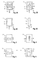
- the Fig. 2A-2D show the optical display unit 11 in the front, rear and side view.
- the optical display unit 11 has a housing 13 with a display surface 14, which faces forward in the working direction A, so that it lies in the field of vision of the rear-view mirror 10A of the vehicle driver of the transport vehicle 10.
- alternately two symbols are displayed on the optical display unit 11, which are set with the operating unit 12 by the machine operator of the road milling machine 1.
- the first symbol that prompts the driver to brake is a cross 15 (FIG. Fig. 2A ), while the second symbol, which prompts the driver to start or continue, is an arrow 16 ( Fig. 2B ).
- the cross 15 and the arrow 16 have different colors, in particular the cross is red and the arrow is green.
- the red cross and the green arrow are composed of a plurality of light segments 15A, 16A, which are connected to a green or red LED, not shown, from behind are illuminated. The individual lighting segments are controlled such that either a red cross 15 or a green arrow 16 is displayed.
- Fig. 2C shows the back of the housing 13 of the optical display unit 11, on which the adjustable rearview mirror 17 of the road milling machine 1 is located.
- the housing 13 of the optical display unit 11 is attached to a bracket 18 on the machine frame 2 ( Fig. 2D ).
- Fig. 3 shows the operating unit 12, which is arranged on the control station 4 in the control panel of the driver of the road milling machine 1.
- the operating unit 12 has a button 20 and two signal lamps 21, 22, in particular red or green LEDs, and an electrical circuit, not shown.
- Operating unit 12 and optical display unit 11 communicate via an electrical line 23.
- the electrical circuit is designed in such a way that after actuation of the button 20 the red cross 15 (FIG. Fig. 2A ) is displayed on the display surface 14 of the optical display unit 11 until the button 20 is pressed again, after which the green arrow 16 (FIG. Fig. 2B ) is shown. After pressing button 20 again, the red cross is displayed again ( Fig. 2A ), etc.
- the operator of the road milling machine 1 can give the driver of the transport vehicle 10 alone by operating the button 20, the required instructions.
- the machine operator is informed about the respective operating state, since the red LED 21 is lit when the red cross is displayed and the green LED 22 is illuminated when the green arrow is displayed.
- Fig. 4 shows an alternative embodiment of the operating unit 12, which differs from that with reference to Fig. 3 described operating unit differs in that instead of the button 20, a switch 24 is provided which has two latching switching positions.
- the first switching position in solid and the second switching position of the switch 24 is shown in dashed lines.
- the red cross Fig. 2A
- the green arrow Fig. 2B
- the operator can recognize only at the position of the switch, which Instructions he gives to the driver of the transport vehicle.
- Signal lamps can be omitted here.
- the optical display unit 11 is part of the road milling machine 1.
- the optical display unit forms a self-contained unit which is arranged in or on the transport vehicle 10.
- the optical display unit can be handed over to the vehicle driver of the transport vehicle and arranged by the vehicle driver in the vehicle cabin.
- the display unit may also be fixedly mounted in the vehicle cabin, for example, be designed as a so-called head-up display.
- the communication between the operating unit 12 and the optical display unit 11 takes place in this embodiment not via an electrical line, but a radio link. Therefore, the operating unit 12 has a transmitting unit 25 only hinted at, and the optical display unit 11 has a receiving unit 26, which is shown only schematically.
- the transmitting unit 25 transmits a radio signal which indicates either one or the other operating state which the receiving unit 26 receives, so that one or the other operating state is displayed on the display surface 14. Otherwise, this embodiment corresponds to the embodiments described above, wherein the corresponding parts are provided with the same reference numerals.
- the display unit 11 also has an acoustic signal transmitter 27, which is located in the housing 13 of the display unit. The acoustic signal generator 27 outputs at each change of the optical display of the one to the other operating state, i. Stopping and driving, an acoustic signal that can clearly perceive the driver of the transport vehicle in the cab, but the construction site staff or other road users does not bother.
Abstract
Description
Die Erfindung betrifft eine selbstfahrende Straßenfräsmaschine zum Bearbeiten von Bodenoberflächen, insbesondere Fahrbahnen.The invention relates to a self-propelled road milling machine for processing of ground surfaces, in particular roadways.
Selbstfahrende Straßenfräsmaschinen sind schon lange bekannt. Sie verfügen über eine Fräseinrichtung, mit der von der Bodenoberfläche Material abgefräst wird, und eine Transporteinrichtung, mit der das abgefräste Material von der Fräseinrichtung zu einer Abwurfstelle gefördert wird. An der Abwurfstelle wird das Material von einem der Straßenfräsmaschine vorausfahrenden oder nachfolgenden Transportfahrzeug aufgenommen.Self-propelled road milling machines have been known for a long time. They have a milling device, with which material is milled from the ground surface, and a transport device with which the milled material is conveyed from the milling device to a discharge point. At the discharge point, the material is picked up by a transport vehicle driving ahead or following the road milling machine.
Die bekannten Straßenfräsmaschinen sind in der Lage, ein verhältnismäßig großes Volumen an Material in einer relativ kurzen Zeit abzufräsen, wobei das Förderband der Transporteinrichtung mit relativ hoher Fördergeschwindigkeit betrieben wird.The known road milling machines are able to mill a relatively large volume of material in a relatively short time, wherein the conveyor belt of the transport device is operated at a relatively high conveying speed.
Bei dem Einsatz der Straßenfräsmaschinen stellt sich während der Fahrt das Problem, das an der Abwurfstelle von dem Förderband abgeworfene Material von dem Transportfahrzeug zeitgleich aufzunehmen. Dabei soll einerseits vermieden werden, dass das Material vor oder hinter sowie neben der Ladefläche des Transportfahrzeugs abgeworfen wird. Andererseits soll vermieden werden, dass das Transportfahrzeug überladen wird. Es wird angestrebt, dass das Material gleichmäßig über die gesamte Länge der Ladefläche abgeworfen wird.When using the road milling machines, the problem arises during the trip to simultaneously pick up the material thrown off the conveyor belt at the discharge point. It should be avoided on the one hand, that the material is dropped in front of or behind and next to the bed of the transport vehicle. On the other hand, it should be avoided that the transport vehicle is overloaded. It is intended that the material is ejected uniformly over the entire length of the loading area.
Die Verladung des abgefrästen Materials auf dem Transportfahrzeug erweist sich insofern als schwierig, als zwar der Maschinenführer der Straßenfräsmaschine, nicht aber der Fahrzeugführer des Transportfahrzeugs den Ladevorgang beobachten kann. Seitdem Straßenfräsmaschinen bekannt sind, ist die übliche Praxis auf der Baustelle, dass der Maschinenführer der Straßenfräsmaschine um den Fahrzeugführer des Transportfahrzeugs zu dirigieren, in Ermangelung besserer Hilfsmittel, die Fahrzeughupe verwendet, die aber eigentlich einen anderen Zweck hat.The loading of the milled material on the transport vehicle proves to be difficult insofar as the machine operator of the road milling machine, but not the driver of the transport vehicle can watch the charging process. Since road milling machines are known, the common practice at the construction site is that the machine operator of the road milling machine is the driver of the transport vehicle to direct, for lack of better tools, the vehicle horn used, but actually has a different purpose.
Bei einer sogenannten Frontlader-Straßenfräsmaschine, bei der sich das Förderband der Transporteinrichtung in Arbeitsrichtung nach vorne über den vorderen Teil des Maschinenrahmens erstreckt, fährt das Transportfahrzeug, beispielsweise ein Muldenkipper, der Straßenfräsmaschine voraus. Dabei ist die Geschwindigkeit des Transportfahrzeugs im Allgemeinen höher als die der Straßenfräsmaschine. Folglich wandert die Abwurfstelle oberhalb der Ladefläche des Transportfahrzeugs von vorne nach hinten. Dies kann der Maschinenführer der Straßenfräsmaschine beobachten. Wenn sich die Abwurfstelle am hinteren Ende der Ladefläche befindet, betätigt der Maschinenführer der Straßenfräsmaschine die Hupe, um den Fahrzeugführer des Transportfahrzeugs aufzufordern, das Transportfahrzeug zu stoppen. Da die Straßenfräsmaschine weiterfährt, wandert die Abwurfstelle zu dem vorderen Ende der Ladefläche. Wenn die Abwurfstelle das vordere Ende der Ladefläche erreicht hat, betätigt der Maschinenführer der Straßenfräsmaschine wieder die Hupe, um den Fahrzeugführer des Transportfahrzeugs zum Anfahren aufzufordern.In a so-called front-loading road milling machine in which the conveyor belt of the transport device extends in the working direction forward over the front part of the machine frame, the transport vehicle, for example a dump truck, precedes the road milling machine. The speed of the transport vehicle is generally higher than that of the road milling machine. Consequently, the discharge point above the loading area of the transport vehicle moves from front to back. This can be observed by the machine operator of the road milling machine. When the discharge point is at the rear end of the bed, the road milling machine operator operates the horn to prompt the vehicle operator to stop the transport vehicle. As the road milling machine continues, the discharge point moves to the front end of the truck bed. When the discharge point has reached the front end of the loading area, the machine operator of the road milling machine actuates the horn again to prompt the driver of the transport vehicle to start.
Die Aufforderung zum Anfahren und Stoppen des Transportfahrzeugs mit Hupsignalen hat sich in der Praxis grundsätzlich bewährt. Daher hat man an dieser üblichen Praxis bisher immer festhalten wollen. Diese Praxis hat verschiedene Nachteile, die aber nicht offensichtlich sind.The request to start and stop the transport vehicle with hopping signals has basically proven itself in practice. Therefore, one has always wanted to stick to this usual practice. This practice has several disadvantages, but they are not obvious.
Zunächst können die Hupsignale zu Irritationen anderer Verkehrsteilnehmer führen, da die Fahrzeugführer der an der Baustelle vorbeifahrenden Fahrzeuge nicht wissen oder nicht erkennen können, dass es sich bei den Hupsignalen um Anweisungen an den Fahrzeugführer des Transportfahrzeugs handelt. Im Übrigen sind die Hupsignale mit Lärm verbunden, der nicht nur das Baustellenpersonal, sondern auch Anwohner in der Nähe der Baustelle insbesondere bei Nachtarbeit stört.First, the horn signals may cause irritation to other road users, as the drivers of vehicles passing by the construction site may not know or recognize that the horn signals are instructions to the driver of the transport vehicle. Incidentally, the hopping signals are associated with noise, which disturbs not only the site staff, but also residents near the site, especially at night work.
Andererseits kann auch der Fahrzeugführer des Transportfahrzeugs durch mögliche Hupsignale der vorbeifahrenden Fahrzeuge irritiert werden, was zu einem Zusammenstoß von Transportfahrzeug und Straßenfräsmaschine oder zum Abwurf des abgefrästen Materials hinter der Ladefläche des Transportfahrzeugs führen kann.On the other hand, the vehicle driver of the transport vehicle can be irritated by possible hopping signals of the passing vehicles, resulting in a collision of transport vehicle and road milling machine or for discharging the milled material behind the back of the transport vehicle can lead.
Die andauernd wiederkehrenden Hupsignale können aber auch dazu führen, dass das Baustellenpersonal nicht mehr zwischen einem Hupsignal, mit dem der Maschinenführer der Straßenfräsmaschine das Baustellenpersonal vor einer Gefahr warnen will, von einem Hupsignal als Anweisung für den Fahrzeugführer des Transportfahrzeugs unterscheiden kann. Folglich verliert das Hupsignal für das Baustellenpersonal seine eigentliche Zweckbestimmung.However, the constantly recurring hopping signals can also mean that the construction site personnel can no longer distinguish between a horn signal with which the machine operator of the road milling machine wants to warn the construction site personnel of a danger from a horn signal as an instruction for the driver of the transport vehicle. Consequently, the horn signal loses its actual purpose for the construction site staff.
Darüber hinaus erfordert die Erkennung der Hupsignale für den Fahrzeugführer des Transportfahrzeugs relativ große Aufmerksamkeit, da die Hupsignale auf der Baustelle überhört werden können. Wenn der Fahrzeugführer des Transportfahrzeugs das Hupsignal überhört, hat er im Nachhinein nicht die Möglichkeit, sich zu vergewissern, welche Anweisungen der Maschinenführer der Straßenfräsmaschine gegeben hat.In addition, the recognition of the horn signals for the driver of the transport vehicle requires relatively much attention, since the hopping signals can be missed on the site. In hindsight, if the driver of the transport vehicle overhears the horn signal, he does not have the opportunity to ascertain what instructions the machine operator has given to the road milling machine.
Der Erfindung liegt daher die Aufgabe zugrunde, eine selbstfahrende Straßenfräsmaschine zu schaffen, mit der sich das abgefräste Material einfach und sicher auf der Ladefläche eines Transportfahrzeugs abladen lässt.The invention is therefore an object of the invention to provide a self-propelled road milling machine with which the milled material can be easily and safely unload on the back of a transport vehicle.
Die Lösung dieser Aufgabe erfolgt erfindungsgemäß mit den Merkmalen des Patentanspruchs 1. Die Unteransprüche betreffen vorteilhafte Ausführungsformen der Erfindung.The solution of this object is achieved according to the invention with the features of claim 1. The subclaims relate to advantageous embodiments of the invention.
Die Erfinder haben auf der Baustelle erkannt, dass die seit langem geübte Praxis, mit Hupsignalen dem Fahrzeugführer des Transportfahrzeugs die erforderlichen Anweisungen zu geben, mit den oben genannten Nachteilen verbunden ist.The inventors have recognized at the construction site that the long-standing practice of giving the necessary instructions to the driver of the transport vehicle with the sound signals is associated with the above-mentioned disadvantages.
Die erfindungsgemäße Straßenfräsmaschine zeichnet sich durch eine Signaleinrichtung aus, die eine Bedieneinheit zur Eingabe von mindestens zwei unterschiedlichen Betriebszuständen durch den Maschinenführer der Straßenfräsmaschine und eine optische Anzeigeeinheit zur Anzeige der mindestens zwei mit der Bedieneinheit vom Maschinenführer der Straßenfräsmaschine vorgegebenen Betriebszustände für den Fahrzeugführer des Transportfahrzeugs umfasst. Die Signaleinrichtung kann auch mehrere Bedieneinheiten oder optische Anzeigeeinheiten umfassen. Mehrere Bedieneinheiten sind beispielsweise sinnvoll, wenn die Straßenfräsmaschine über mehrere Fahrstände verfügt. Mehrere Anzeigeeinheiten sind beispielsweise dann sinnvoll, wenn sie redundant angeordnet werden, z. B. paarweise angeordnet werden, um unter allen Betriebsbedingungen den freien Blick auf mindestens eine der Anzeigeeinheiten sicher zu stellen. Die optische Anzeigeeinheit kann an der Straßenfräsmaschine oder als selbstständige Einheit an dem Transportfahrzeug vorgesehen sein.The road milling machine according to the invention is characterized by a signaling device which has an operating unit for inputting at least two different operating states by the machine operator of the road milling machine and an optical display unit for displaying the at least two with the operating unit from Machine operator of the road milling machine predetermined operating conditions for the driver of the transport vehicle includes. The signaling device may also comprise a plurality of operating units or optical display units. Several control units are useful, for example, if the road milling machine has several control stations. Several display units are useful, for example, if they are arranged redundantly, z. B. be arranged in pairs to ensure the free view of at least one of the display units under all operating conditions. The optical display unit may be provided on the road milling machine or as a separate unit on the transport vehicle.
Unter dem ersten Betriebszustand wird die Aufforderung zum Bremsen bzw. Anhalten des Transportfahrzeugs und unter dem zweiten Betriebszustand die Aufforderung zum Anfahren bzw. Weiterfahren des Transportfahrzeugs verstanden. Entscheidend ist, dass die Anzeige der beiden Betriebszustände optisch ist. Die optische Aufforderung zum Bremsen und Anfahren kann andere Verkehrsteilnehmer und das Baustellenpersonal im Gegensatz zu den Hupsignalen nicht irritieren. Von Vorteil ist auch, dass die optische Anzeige für den Fahrzeugführer des Transportfahrzeugs immer präsent ist. Im Gegensatz zu den Hupsignalen kann die Aufforderung zum Bremsen und Anfahren nicht überhört werden. Selbst wenn der Fahrzeugführer des Transportfahrzeugs in dem Moment nicht aufmerksam ist, an dem der Maschinenführer der Straßenfräsmaschine das Signal gibt, kann der Fahrzeugführer des Transportfahrzeugs an dem bleibenden optischen Signal jederzeit erkennen, ob das Transportfahrzeug fahren oder stehen soll. Dabei bleibt die Signalwirkung der Hupe sowohl für die anderen Verkehrsteilnehmer als auch das Baustellenpersonal erhalten. Das optische Signal der Anzeigeeinheit ist auch dann wahrnehmbar, wenn der Fahrzeugführer des Transportfahrzeugs durch Umgebungslärm gestört wird. Weiterhin ist die optische Anzeige nicht mit einer Lärmbelästigung für das Baustellenpersonal oder die Anwohner verbunden.Under the first operating state, the request for braking or stopping the transport vehicle and under the second operating state, the request to start or continue the transport vehicle understood. It is crucial that the display of the two operating states is visual. The optical request for braking and starting can not irritate other road users and construction site personnel, in contrast to the hopping signals. Another advantage is that the visual display for the driver of the transport vehicle is always present. In contrast to the hopping signals, the request for braking and starting can not be overheard. Even if the driver of the transport vehicle is not attentive at the moment when the driver of the road milling machine gives the signal, the driver of the transport vehicle can always recognize from the permanent optical signal whether the transport vehicle should travel or stand. The signal effect of the horn remains for both the other road users and the construction site staff. The visual signal of the display unit is also perceptible when the driver of the transport vehicle is disturbed by environmental noise. Furthermore, the visual display is not associated with noise pollution for the site personnel or residents.
Die optische Anzeigeeinheit kann unterschiedlich ausgebildet sein. Allein entscheidend ist, dass die Betriebszustände optisch angezeigt werden. Bei einer bevorzugten Ausführungsform werden zwei Betriebszustände angezeigt, wobei der erste Betriebszustand durch ein erstes Symbol und der zweite Betriebszustand durch ein zweites Symbol angezeigt wird, die voneinander verschieden sind. Es können unterschiedliche Symbole verwandt werden. Diese Symbole sollten aber nicht den Symbolen entsprechen, die auf Straßenschildern verwendet werden. Vorzugsweise wird die Aufforderung zum Bremsen bzw. Anhalten als Kreuz und zum Anfahren bzw. Fahren als Pfeil signalisiert. Beide Symbole können auch unterschiedliche Farben haben. Beispielsweise kann das Kreuz rot und der Pfeil grün angezeigt werden. Auch können die Symbole blinken oder über die Anzeigefläche laufen, um die Aufmerksamkeit des Fahrzeugführers weiter zu erhöhen.The optical display unit can be designed differently. The only decisive factor is that the operating conditions are visually displayed. In a preferred embodiment, two operating conditions are indicated, wherein the first operating state by a first symbol and the second operating state by a second Icon is displayed, which are different from each other. Different symbols can be used. However, these symbols should not correspond to the symbols used on street signs. Preferably, the request for braking or stopping is signaled as a cross and for starting or driving as an arrow. Both symbols can also have different colors. For example, the cross may be displayed in red and the arrow in green. Also, the icons may flash or scroll across the display area to further increase the attention of the driver.
Die Bedieneinheit ist vorzugsweise am Fahrstand der Straßenfräsmaschine angeordnet, an dem der Maschinenführer die Ladefläche des Transportfahrzeugs beobachten und die Bedieneinheit bedienen kann.The operating unit is preferably arranged on the control station of the road milling machine, on which the machine operator can observe the loading area of the transport vehicle and operate the operating unit.
Die Bedieneinheit kann als Bedienelemente über ein oder mehrere Tasten oder Schalter verfügen, mit denen sich die beiden Betriebszustände vorgeben lassen.The operating unit may have as control elements via one or more keys or switches, with which the two operating states can be specified.
Bei einer besonders bevorzugten Ausführungsform weist die Bedieneinheit nur ein Bedienelement auf, wodurch Fehlbedienungen vermieden werden können. Vorzugsweise ist das eine Bedienelement ein Taster, wobei die Bedieneinheit derart ausgebildet ist, dass nach Betätigung des Tasters der eine Betriebszustand solange angezeigt wird, bis der Taster erneut betätigt wird, wonach dann der andere Betriebszustand angezeigt wird. Folglich kann der Maschinenführer einfach durch Betätigung des Tasters zwischen den beiden Betriebszuständen umschalten, die jeweils dauerhaft mit der optischen Anzeigeeinheit angezeigt werden.In a particularly preferred embodiment, the operating unit has only one operating element, whereby incorrect operation can be avoided. Preferably, the one control element is a button, wherein the operating unit is designed such that after actuation of the button, an operating state is displayed until the button is pressed again, after which then the other operating state is displayed. Consequently, the operator can easily switch between the two operating states by pressing the button, each of which is permanently displayed with the optical display unit.
Es ist aber auch möglich, dass an der Bedieneinheit zwei Taster vorzusehen, wobei mit dem einen Taster der eine Betriebszustand und mit dem anderen Taster der andere Betriebszustand vorgeben wird. Dann ist die Bedieneinheit derart ausgebildet, dass nach der Betätigung des einen Tasters der eine Betriebszustand so lange angezeigt wird, bis der andere Taster betätigt wird, nach dessen Betätigung der andere Betriebszustand angezeigt wird.But it is also possible that provide two buttons on the control unit, with the one button of an operating condition and with the other button of the other operating state will specify. Then, the operating unit is designed such that after the operation of a button, the one operating state is displayed until the other button is pressed, after the operation of the other operating state is displayed.
Insbesondere wenn das Betriebselement als Taster ausgebildet ist, erweist sich vorteilhaft, wenn die vorgegebenen Betriebszustände dem Maschinenführer der Straßenfräsmaschine signalisiert werden. Dies kann beispielsweise durch optische Symbole auf der Bedieneinheit, oder auf der Rückseite der Anzeigeeinheit erfolgen. Es können beispielsweise Signallampen oder der gleichen vorgesehen sein.In particular, when the operating element is designed as a button, it proves advantageous if the predetermined operating conditions are signaled to the machine operator of the road milling machine. This can be done for example by optical symbols on the control unit, or on the back of the display unit. For example, signal lamps or the like may be provided.
Eine alternative Ausführungsform sieht anstelle eines oder zwei Taster als Bedienelement ein Schalter mit mindestens zwei Schaltstellungen vor, wobei mit der einen Schaltstellung der eine und mit der anderen Schaltstellung der andere Betriebszustand vorgegeben wird. Vorzugsweise hat der Schalter zwei rastende Schaltstellungen, so dass der Maschinenführer allein an der Stellung des Schalters die Vorgabe des einen oder anderen Betriebszustands sofort erkennen kann, ohne dass weiter optische Signale zur Darstellung des Betriebszustands erforderlich sind.An alternative embodiment provides for a switch with at least two switching positions instead of one or two buttons as the operating element, wherein the one and with the other switching position of the other operating state is specified with the one switching position. Preferably, the switch has two latching switching positions, so that the machine operator can recognize the specification of one or the other operating state alone at the position of the switch, without further optical signals to represent the operating state are required.
Bei einer Frontlader-Straßenfräsmaschine, bei der sich das Förderband der Transporteinrichtung in Arbeitsrichtung nach vorne über den vorderen Teil des Maschinenrahmens erstreckt, weist die optische Anzeigeeinheit vorzugsweise eine Anzeigefläche auf, die in Arbeitsrichtung der Fräsmaschine weist. Folglich kann der Fahrzeugführer des der Frontlader-Straßenfräsmaschine vorausfahrenden Transportfahrzeugs die Anzeigefläche der optischen Anzeigeeinheit im Rückspiegel erkennen.In a front-loading road milling machine in which the conveyor belt of the transport device extends in the working direction forward over the front part of the machine frame, the optical display unit preferably has a display surface facing in the working direction of the milling machine. Consequently, the driver of the transport vehicle ahead of the front-end road milling machine can recognize the display surface of the optical display unit in the rearview mirror.
Die optische Anzeigeeinheit mit der Anzeigefläche ist an der Straßenfräsmaschine vorteilhafterweise derart angeordnet, dass der Fahrzeugführer des Transportfahrzeugs die Anzeigefläche in dem linken und/ oder rechten Rückspiegel des Transportfahrzeugs erkennen kann. Vorzugsweise ist die optische Anzeigeeinheit an einer oder beiden Längsseiten des Maschinenrahmens angeordnet. Die Anzeigeeinheit sollte auf der Höhe angeordnet sein, auf der sich der Rückspiegel des Transportfahrzeugs befindet.The visual display unit with the display surface is advantageously arranged on the road milling machine such that the driver of the transport vehicle can recognize the display surface in the left and / or right rearview mirror of the transport vehicle. Preferably, the optical display unit is arranged on one or both longitudinal sides of the machine frame. The display unit should be located at the level at which the rearview mirror of the transport vehicle is located.
Die bekannten Straßenfräsmaschinen weisen an einer oder beiden Längsseiten einen Rückspiegel auf. Eine besonders bevorzugte Ausführungsform sieht vor, dass die optische Anzeigeeinheit an der Rückseite des Rückspiegels der Straßenfräsmaschine angeordnet ist. Diese Ausführungsform hat den Vorteil, dass die Anzeigeeinheit Bestandteil des Rückspiegels ist, der im Blickfeld des Fahrzeugführers des Transportfahrzeugs angeordnet ist. Ferner sind mit der Integration der Anzeigeeinheit in den Rückspiegel keine zusätzlichen Anbauteile an der Straßenfräsmaschine erforderlich, mit denen die Sicht des Fahrzeugführers behindert werden könnte.The known road milling machines have a rearview mirror on one or both longitudinal sides. A particularly preferred embodiment provides that the optical display unit is arranged on the rear side of the rearview mirror of the road milling machine. This embodiment has the advantage that the display unit is part of the rearview mirror, which is arranged in the field of vision of the vehicle driver of the transport vehicle. Furthermore, with the integration of the display unit in the rearview mirror no additional attachments to the road milling machine required with which the view of the driver could be hindered.
Bei einer alternativen Ausführungsform ist die optische Anzeigeeinheit als eine selbstständige Einheit ausgebildet, die nicht an der Straßenfräsmaschine angeordnet ist, sondern in oder an dem Transportfahrzeug angeordnet wird. Bei dieser Ausführungsform weist die Bedieneinheit eine Sendeeinheit zum Senden eines Signals für die mindestens zwei Betriebszustände und die Anzeigeeinheit eine Empfangseinheit zum Empfangen des Signals für die mindestens zwei Betriebszustände auf. Sende- und Empfangseinheit können dem Fachmann bekannte Funksender und -empfänger sein. Die alternative Ausführungsform hat den Vorteil, dass die optische Anzeigeeinheit beispielsweise in der Fahrerkabine direkt im Blickfeld des Fahrzeugführers des Transportfahrzeugs angeordnet werden kann. Damit ist es nicht erforderlich, dass der Fahrzeugführer des Transportfahrzeugs die Anzeigeeinheit über den Rückspiegel beobachtet. Beispielsweise ist es möglich, die optische Anzeigeeinheit als eine portable Einheit auszubilden, die dem Fahrzeugführer des Transportfahrzeugs auf der Baustelle übergeben wird. Es ist aber auch möglich, die optische Anzeigeeinheit fest in das Transportfahrzeug einzubauen. Beispielsweise ist es möglich, die optische Anzeigeeinheit als sogenanntes Head-Up-Display auszubilden, das dem Fachmann bekannt ist.In an alternative embodiment, the optical display unit is formed as a self-contained unit, which is not arranged on the road milling machine, but is arranged in or on the transport vehicle. In this embodiment, the operating unit has a transmitting unit for transmitting a signal for the at least two operating states and the display unit a receiving unit for receiving the signal for the at least two operating states. Transmitting and receiving unit can be known to the expert radio transmitter and receiver. The alternative embodiment has the advantage that the optical display unit can be arranged, for example, in the driver's cab directly in the field of vision of the vehicle driver of the transport vehicle. Thus, it is not necessary that the driver of the transport vehicle observes the display unit via the rearview mirror. For example, it is possible to form the optical display unit as a portable unit, which is handed over to the driver of the transport vehicle at the construction site. But it is also possible to install the optical display unit firmly in the transport vehicle. For example, it is possible to design the optical display unit as a so-called head-up display, which is known to the person skilled in the art.
Bei einer weiteren bevorzugten Ausführungsform wird die Signalwirkung der optischen Anzeigeeinheit noch dadurch weiter erhöht, dass beim Wechsel der Anzeige von dem einen auf den anderen Betriebszustand zusätzlich ein akustisches Signal für den Fahrzeugführer des Transportfahrzeugs gegeben wird. Dies ist insbesondere bei der Ausführungsform von Vorteil, bei der die optische Anzeigeeinheit eine selbstständige Einheit bildet, die in der Fahrerkabine des Transportfahrzeugs angeordnet werden kann. In diesem Fall braucht das akustische Signal keine große Lautstärke haben, so dass es für andere nicht störend ist.In a further preferred embodiment, the signal effect of the optical display unit is further increased by the fact that when changing the display from one to the other operating state additionally an audible signal for the driver of the transport vehicle is given. This is particularly advantageous in the embodiment in which the visual display unit forms a self-contained unit that can be arranged in the cab of the transport vehicle. In this case, the acoustic signal need not have a high volume, so it is not disturbing to others.
Im Folgenden werden mehrere Ausführungsbeispiele der Erfindung unter Bezugnahme auf die Zeichnungen näher erläutert.In the following, several embodiments of the invention will be explained in more detail with reference to the drawings.
Es zeigen:
- Fig. 1
- Eine Straßenfräsmaschine zusammen mit einem Transportfahrzeug in vereinfachter Darstellung,
- Fig. 2 A
- die optische Anzeigeeinheit in der Vorderansicht, wobei das Symbol zum Anhalten angezeigt wird,
- Fig. 2 B
- die optische Anzeigeeinheit, wobei das Symbol zum Anfahren angezeigt wird,
- Fig. 2C
- die optische Anzeigeeinheit in der Rückansicht,
- Fig. 2D
- die optische Anzeigeeinheit in der Seitenansicht,
- Fig. 3
- ein erstes Ausführungsbeispiel der Bedieneinheit,
- Fig. 4
- ein zweites Ausführungsbeispiel der Bedieneinheit,
- Fig. 5
- ein weiteres Ausführungsbeispiel der Bedieneinheit und
- Fig. 6
- ein weiteres Ausführungsbeispiel der Anzeigeeinheit.
- Fig. 1
- A road milling machine together with a transport vehicle in a simplified representation,
- Fig. 2 A
- the optical display unit in the front view, wherein the symbol for stopping is displayed,
- Fig. 2 B
- the visual display unit, wherein the symbol for starting is displayed,
- Fig. 2C
- the optical display unit in the rear view,
- Fig. 2D
- the optical display unit in the side view,
- Fig. 3
- a first embodiment of the operating unit,
- Fig. 4
- A second embodiment of the operating unit,
- Fig. 5
- Another embodiment of the control unit and
- Fig. 6
- a further embodiment of the display unit.
Das abgefräste Material wird mit einer Transporteinrichtung 6 auf ein der Straßenfräsmaschine vorausfahrendes Transportfahrzeug 10, beispielsweise ein Muldenkipper, verladen. Die Transporteinrichtung 6 weist ein Förderband 7 auf, dass sich über den vorderen Teil des Maschinenrahmens 2 in Arbeitsrichtung A nach vorne erstreckt. Das mit relativ hoher Geschwindigkeit geförderte Material wird in Arbeitsrichtung A vor dem vorderen Ende des Förderbands 7 an der Abwurfstelle 8 oberhalb der Ladefläche 9 des Transportfahrzeugs 10 abgeworfen.The milled material is loaded by means of a
Das Transportfahrzeug 10 wird wie folgt beladen. Das Transportfahrzeug 10 fährt mit etwas höherer Geschwindigkeit als die Straßenfräsmaschine 1, so dass die Abwurfstelle 8 von dem vorderen zu dem hinteren Ende der Ladefläche 9 wandert. Dann stoppt das Transportfahrzeug 10, während die Straßenfräsmaschine 1 weiterfährt. Folglich wandert die Abwurfstelle 8 wieder zu dem vorderen Ende der Ladefläche 9. Dieser Vorgang wird solange wiederholt, bis das Transportfahrzeug vollständig beladen ist.The
Die Straßenfräsmaschine 1 verfügt über eine Einrichtung, die dem Fahrzeugführer des Transportfahrzeugs 10 signalisiert, wann er das Transportfahrzeug anfahren oder anhalten soll. Diese Einrichtung wird nachfolgend im Einzelnen beschrieben.The road milling machine 1 has a device that signals to the driver of the
Die Signaleinrichtung umfasst eine optische Anzeigeeinheit 11 und eine Bedieneinheit 12. Bei dem ersten Ausführungsbeispiel sind die optische Anzeigeeinheit 11 und der Rückspiegel der Straßenfräsmaschine in einem gemeinsamen Gehäuse angeordnet, so dass sie eine Einheit bilden, die bei dem vorliegenden Ausführungsbeispiel an der in Arbeitsrichtung A linken Seite des Maschinenrahmens 2 nach außen vorstehend befestigt ist. In
Die optische Anzeigeeinheit 11 weist ein Gehäuse 13 mit einer Anzeigefläche 14 auf, die in Arbeitsrichtung A nach vorne weist, so dass sie im Blickfeld des Rückspiegels 10A des Fahrzeugführers des Transportfahrzeugs 10 liegt.The
Bei dem vorliegenden Ausführungsbeispiel werden auf der optischen Anzeigeeinheit 11 wechselweise zwei Symbole angezeigt, die mit der Bedieneinheit 12 vom Maschinenführer der Straßenfräsmaschine 1 vorgegeben werden. Das erste Symbol, mit dem der Fahrzeugführer zum Bremsen bzw. Anhalten aufgefordert wird, ist ein Kreuz 15 (
Bei den oben beschriebenen Ausführungsbeispielen ist die optische Anzeigeeinheit 11 Bestandteil der Straßenfräsmaschine 1. Bei einer alternativen Ausführungsform bildet die optische Anzeigeeinheit aber eine selbstständige Einheit, die in oder an dem Transportfahrzeug 10 angeordnet wird. Beispielsweise kann die optische Anzeigeeinheit dem Fahrzeugführer des Transportfahrzeugs übergeben und von diesem in der Fahrzeugkabine angeordnet werden. Die Anzeigeeinheit kann aber auch fest in der Fahrzeugkabine montiert sein, beispielsweise als sogenanntes Head-Up-Display ausgebildet sein. Die Kommunikation zwischen der Bedieneinheit 12 und der optischen Anzeigeeinheit 11 erfolgt bei diesem Ausführungsbeispiel nicht über eine elektrische Leitung, sondern eine Funkverbindung. Daher weist die Bedieneinheit 12 eine nur andeutungsweise dargestellte Sendeeinheit 25 und die optische Anzeigeeinheit 11 eine nur andeutungsweise dargestellte Empfangseinheit 26 auf. Die Sendeeinheit 25 sendet ein Funksignal, das entweder den einen oder anderen Betriebszustand angibt, welches die Empfangseinheit 26 empfängt, so dass der eine oder andere Betriebszustand auf der Anzeigefläche 14 angezeigt wird. Ansonsten entspricht diese Ausführungsform den oben beschriebenen Ausführungsbeispielen, wobei auch die einander entsprechenden Teile mit den gleichen Bezugszeichen versehen sind. Die Anzeigeeinheit 11 verfügt neben der Anzeigefläche 14 noch über einen akustischen Signalgeber 27, der sich in dem Gehäuse 13 der Anzeigeeinheit befindet. Der akustische Signalgeber 27 gibt bei jedem Wechsel der optischen Anzeige von dem einen auf den anderen Betriebszustand, d.h. Anhalten und Fahren, ein akustisches Signal, das der Fahrzeugführer des Transportfahrzeugs in der Fahrerkabine deutlich wahrnehmen kann, das Baustellenpersonal oder die übrigen Verkehrsteilnehmer aber nicht stört.In the embodiments described above, the
Claims (12)
einem Maschinenrahmen (2),
einem an dem Maschinenrahmen angeordneten Fahrstand (4) für den Maschinenführer der Straßenfräsmaschine,
einer Fräseinrichtung (5) zum Abfräsen von Material,
einer Transporteinrichtung (7) zum Fördern des abgefrästen Materials zu einer Abwurfstelle, an der das abgefräste Material von einem der Straßenfräsmaschine vorausfahrenden oder nachfolgenden Transportfahrzeug aufgenommen wird,
dadurch gekennzeichnet, dass
die Straßenfräsmaschine mindestens eine Bedieneinheit (12) zur Eingabe von mindestens zwei unterschiedlichen Betriebszuständen durch den Maschinenführer der Straßenfräsmaschine aufweist, wobei mindestens eine optische Anzeigeinheit (11) zur Anzeige der mindestens zwei mit der Bedieneinheit vom Maschinenführer der Straßenfräsmaschine vorgegebenen Betriebszustände für den Fahrzeugführer des der Straßenfräsmaschine vorausfahrenden oder nachfolgenden Transportfahrzeugs vorgesehen ist.Self-propelled road milling machine, with
a machine frame (2),
a control station (4) arranged on the machine frame for the machine operator of the road milling machine,
a milling device (5) for milling material,
a transport device (7) for conveying the milled material to a discharge point at which the milled material is picked up by a transport vehicle driving ahead or following the road milling machine,
characterized in that
the road milling machine having at least one operating unit (12) for inputting at least two different operating states by the machine operator of the road milling machine, wherein at least one optical display unit (11) for displaying the at least two predetermined by the operator of the road milling machine operating conditions for the driver of the road milling machine is provided preceding or subsequent transport vehicle.
Applications Claiming Priority (1)
| Application Number | Priority Date | Filing Date | Title |
|---|---|---|---|
| DE102009041842A DE102009041842A1 (en) | 2009-09-18 | 2009-09-18 | Self-propelled road milling machine |
Publications (3)
| Publication Number | Publication Date |
|---|---|
| EP2298997A2 true EP2298997A2 (en) | 2011-03-23 |
| EP2298997A3 EP2298997A3 (en) | 2014-10-29 |
| EP2298997B1 EP2298997B1 (en) | 2017-03-29 |
Family
ID=43567865
Family Applications (1)
| Application Number | Title | Priority Date | Filing Date |
|---|---|---|---|
| EP10009201.4A Active EP2298997B1 (en) | 2009-09-18 | 2010-09-04 | Self-propelled road milling machine |
Country Status (4)
| Country | Link |
|---|---|
| US (3) | US8979424B2 (en) |
| EP (1) | EP2298997B1 (en) |
| CN (2) | CN102021878A (en) |
| DE (1) | DE102009041842A1 (en) |
Cited By (4)
| Publication number | Priority date | Publication date | Assignee | Title |
|---|---|---|---|---|
| CN104003658A (en) * | 2014-04-01 | 2014-08-27 | 河北寰兴建筑材料有限公司 | Multi-color pavement concrete ready-mixed mortar |
| EP2573266A3 (en) * | 2011-09-22 | 2015-09-30 | BOMAG GmbH | Method for controlling a loading procedure of a transport vehicle with milled material, apparatus for carrying out such a method and a device for milling |
| CN112942028A (en) * | 2019-12-10 | 2021-06-11 | 卡特彼勒路面机械公司 | Work machine and system for monitoring wear of components of work machine |
| EP2573267B2 (en) † | 2011-09-22 | 2022-05-04 | BOMAG GmbH | Maintenance train with a milling device and a transport device and a sensor device for distance monitoring, milling device having a sensor device and method for distance monitoring in a maintenance train |
Families Citing this family (26)
| Publication number | Priority date | Publication date | Assignee | Title |
|---|---|---|---|---|
| DE102008008260B4 (en) * | 2008-02-08 | 2010-09-09 | Wirtgen Gmbh | Control of a mining machine and mining machine |
| US20130189032A1 (en) * | 2011-12-13 | 2013-07-25 | Gestion D'Équipements. B.T. Inc. | Material management system and method for continuous cold in-place recycling of pavement |
| DE202012003689U1 (en) * | 2012-04-10 | 2012-05-02 | Joseph Vögele AG | Construction machine with signaling device |
| DE102012215005A1 (en) | 2012-08-23 | 2014-02-27 | Wirtgen Gmbh | Self-propelled milling machine, as well as method for steering a self-propelled milling machine |
| DE102012215013A1 (en) | 2012-08-23 | 2014-02-27 | Wirtgen Gmbh | Self-propelled milling machine, as well as method for unloading milled material |
| CN102890490A (en) * | 2012-09-25 | 2013-01-23 | 三一重工股份有限公司 | Pavement construction machine group and matched guidance system thereof |
| CN103064418A (en) * | 2012-12-26 | 2013-04-24 | 三一重工股份有限公司 | Milling machine dumper travelling control device and milling machine unit |
| CN103147379B (en) * | 2013-02-28 | 2015-04-01 | 中联重科股份有限公司 | Method, device and system for controlling loading angles of milling machines, and milling machine |
| DE102013004995A1 (en) | 2013-03-21 | 2014-09-25 | Bomag Gmbh | Work train with a self-propelled road milling machine and a transport vehicle, ground milling machine for such a work train, signaling device for the work train and method for transmitting driving commands from a road milling machine to a transport vehicle |
| DE102014216603B4 (en) | 2014-08-21 | 2018-02-22 | Wirtgen Gmbh | Self-propelled milling machine, as well as method for unloading milled material |
| DE102014216763B4 (en) | 2014-08-22 | 2018-07-26 | Wirtgen Gmbh | Self-propelled milling machine, as well as method for unloading milled material |
| DE102014216713B4 (en) | 2014-08-22 | 2018-09-06 | Wirtgen Gmbh | Self-propelled milling machine, as well as method for unloading milled material |
| CN104153282A (en) * | 2014-08-22 | 2014-11-19 | 山推工程机械股份有限公司 | Pavement milling machine |
| PL3124698T3 (en) * | 2015-07-28 | 2018-01-31 | Voegele Ag J | Road finisher with roller indication display device |
| US9783112B2 (en) | 2015-10-27 | 2017-10-10 | Cnh Industrial America Llc | Rear windshield implement status heads-up display |
| US20170130405A1 (en) * | 2015-11-05 | 2017-05-11 | Caterpillar Paving Products Inc. | Truck position control system for milling operations |
| US10688901B2 (en) * | 2016-03-23 | 2020-06-23 | Bomag Gmbh | Intermediate storage vehicle for milled material and work train |
| DE102016003562B4 (en) | 2016-03-23 | 2022-09-22 | Bomag Gmbh | Milling train and method |
| DE102016222589B4 (en) | 2016-11-16 | 2020-01-16 | Wirtgen Gmbh | Self-propelled milling machine and method for controlling a self-propelled milling machine |
| JP6776177B2 (en) * | 2017-05-08 | 2020-10-28 | 福田道路株式会社 | Construction vehicle guidance system |
| DE102017220869A1 (en) | 2017-11-22 | 2019-05-23 | Wirtgen Gmbh | Self-propelled milling machine, method for automatically loading a means of transport with milled material, as well as road or soil treatment unit |
| DE102019104218A1 (en) | 2019-02-19 | 2020-08-20 | Wirtgen Gmbh | Work train, comprising a tillage machine and another vehicle as well as an automated distance monitoring |
| DE102019104850A1 (en) | 2019-02-26 | 2020-08-27 | Wirtgen Gmbh | Paver |
| JP7274399B2 (en) * | 2019-10-29 | 2023-05-16 | 酒井重工業株式会社 | construction vehicle alarm |
| CN111354199B (en) * | 2020-02-19 | 2021-09-03 | 广州小鹏汽车科技有限公司 | Control method, control device, vehicle, and storage medium |
| DE102021206027A1 (en) | 2021-06-14 | 2022-12-15 | Robert Bosch Gesellschaft mit beschränkter Haftung | Method for assisting a driver of a transport vehicle when assuming a loading position |
Citations (2)
| Publication number | Priority date | Publication date | Assignee | Title |
|---|---|---|---|---|
| US20040004544A1 (en) * | 2002-02-20 | 2004-01-08 | Scott William Knutson | Device used to aid in the loading and unloading of vehicles and implements |
| EP1507925B1 (en) * | 2002-05-28 | 2006-02-01 | WIRTGEN GmbH | Suction device and suction method for the disposal of dust in milling machines |
Family Cites Families (21)
| Publication number | Priority date | Publication date | Assignee | Title |
|---|---|---|---|---|
| US2485719A (en) * | 1949-10-25 | Traffic safety light | ||
| DE1930596A1 (en) * | 1968-06-26 | 1970-03-12 | Burt Kenneth L | Traffic control device by means of vision devices |
| US3866169A (en) * | 1973-03-09 | 1975-02-11 | Claude R Haglund | Vehicle signalling apparatus |
| DE19531662A1 (en) * | 1995-08-29 | 1997-03-06 | Claas Ohg | Device for the automatic filling of loading containers |
| DE19547698C2 (en) * | 1995-12-20 | 2000-08-17 | Wirtgen Gmbh | Device and method for milling hard surfaces, in particular road surfaces |
| DE29617116U1 (en) * | 1996-10-01 | 1996-11-21 | Voegele Ag J | Built-in train |
| US7806070B2 (en) * | 2001-06-21 | 2010-10-05 | George Lamont Williams | Method and apparatus for a vehicle forward direction signal |
| US6864787B1 (en) * | 2001-12-05 | 2005-03-08 | Sherri Coseo Veach | Front safety brake lights |
| DE10357074B3 (en) * | 2003-12-04 | 2005-05-19 | Wirtgen Gmbh | Self-propelled road surfacing machine with direct mechanical drive of working roller from drive take-off shaft of internal combustion engine |
| DE102005044211A1 (en) * | 2005-09-12 | 2007-03-22 | Wirtgen Gmbh | Self-propelled construction machine, as well as lifting column for a construction machine |
| DE102006062129B4 (en) * | 2006-12-22 | 2010-08-05 | Wirtgen Gmbh | Road construction machine and method for measuring the cutting depth |
| RU2401904C2 (en) * | 2006-12-22 | 2010-10-20 | Виртген Гмбх | Road carpet crusher and method of locating crusher outline in parallel with earth surface |
| US8465105B2 (en) * | 2007-01-18 | 2013-06-18 | Cmi Terex Corporation | Control system for cutter drum |
| DE102007007970B4 (en) * | 2007-02-17 | 2009-11-26 | Wirtgen Gmbh | Construction machine, in particular road construction machine |
| EP2006448A1 (en) * | 2007-06-21 | 2008-12-24 | Leica Geosystems AG | Paving machine for applying a cover layer made of concrete or asphalt material |
| ATE546991T1 (en) * | 2007-08-03 | 2012-03-15 | Agrocom Gmbh & Co Agrarsystem Kg | AGRICULTURAL WORKING MACHINE |
| US8077023B2 (en) * | 2009-05-08 | 2011-12-13 | Hal's Construction, Inc. | Operational signal system and signal light arrangement |
| EP2256246B1 (en) * | 2009-05-20 | 2018-07-04 | Joseph Vögele AG | Paving machines for applying a cover layer of a road surface |
| DE102011114183A1 (en) * | 2011-09-22 | 2013-03-28 | Bomag Gmbh | Method for controlling a loading process of a transport vehicle with milled material, device for carrying out such a method and milling device |
| DE102011114185A1 (en) * | 2011-09-22 | 2013-03-28 | Bomag Gmbh | Work train with a milling device and a transport device with a sensor device for distance monitoring, milling device with a sensor device and method for distance monitoring in a work train |
| DE102012215005A1 (en) * | 2012-08-23 | 2014-02-27 | Wirtgen Gmbh | Self-propelled milling machine, as well as method for steering a self-propelled milling machine |
-
2009
- 2009-09-18 DE DE102009041842A patent/DE102009041842A1/en not_active Withdrawn
-
2010
- 2010-09-04 EP EP10009201.4A patent/EP2298997B1/en active Active
- 2010-09-14 US US12/881,337 patent/US8979424B2/en active Active
- 2010-09-19 CN CN2010102863483A patent/CN102021878A/en active Pending
- 2010-09-19 CN CN2010205349177U patent/CN202031012U/en not_active Expired - Lifetime
-
2015
- 2015-02-27 US US14/634,379 patent/US9133587B2/en active Active
- 2015-09-09 US US14/848,544 patent/US9435086B2/en active Active
Patent Citations (2)
| Publication number | Priority date | Publication date | Assignee | Title |
|---|---|---|---|---|
| US20040004544A1 (en) * | 2002-02-20 | 2004-01-08 | Scott William Knutson | Device used to aid in the loading and unloading of vehicles and implements |
| EP1507925B1 (en) * | 2002-05-28 | 2006-02-01 | WIRTGEN GmbH | Suction device and suction method for the disposal of dust in milling machines |
Cited By (6)
| Publication number | Priority date | Publication date | Assignee | Title |
|---|---|---|---|---|
| EP2573266A3 (en) * | 2011-09-22 | 2015-09-30 | BOMAG GmbH | Method for controlling a loading procedure of a transport vehicle with milled material, apparatus for carrying out such a method and a device for milling |
| EP2573267B2 (en) † | 2011-09-22 | 2022-05-04 | BOMAG GmbH | Maintenance train with a milling device and a transport device and a sensor device for distance monitoring, milling device having a sensor device and method for distance monitoring in a maintenance train |
| CN104003658A (en) * | 2014-04-01 | 2014-08-27 | 河北寰兴建筑材料有限公司 | Multi-color pavement concrete ready-mixed mortar |
| CN104003658B (en) * | 2014-04-01 | 2016-06-22 | 河北寰兴建筑材料有限公司 | Multiple colored road surface concrete premixing mortar |
| CN112942028A (en) * | 2019-12-10 | 2021-06-11 | 卡特彼勒路面机械公司 | Work machine and system for monitoring wear of components of work machine |
| CN112942028B (en) * | 2019-12-10 | 2024-02-06 | 卡特彼勒路面机械公司 | Work machine and system for monitoring wear of a component of a work machine |
Also Published As
| Publication number | Publication date |
|---|---|
| US9435086B2 (en) | 2016-09-06 |
| EP2298997A3 (en) | 2014-10-29 |
| US20150167261A1 (en) | 2015-06-18 |
| US20110123268A1 (en) | 2011-05-26 |
| DE102009041842A1 (en) | 2011-09-01 |
| CN202031012U (en) | 2011-11-09 |
| US9133587B2 (en) | 2015-09-15 |
| CN102021878A (en) | 2011-04-20 |
| US8979424B2 (en) | 2015-03-17 |
| EP2298997B1 (en) | 2017-03-29 |
| US20160060827A1 (en) | 2016-03-03 |
Similar Documents
| Publication | Publication Date | Title |
|---|---|---|
| EP2298997B1 (en) | Self-propelled road milling machine | |
| EP2280859B1 (en) | Route monitoring system for a vehicle and method for operating the same | |
| EP2573267B1 (en) | Maintenance train with a milling device and a transport device and a sensor device for distance monitoring, milling device having a sensor device and method for distance monitoring in a maintenance train | |
| DE10352733A1 (en) | Motor vehicle steering wheel has a driver communications interface permitting display of information to the driver and input of commands by the driver with minimal distraction from the driving situation | |
| EP0696527A2 (en) | Direction indicator | |
| WO2000071398A1 (en) | Vehicle treatment system and method for operating the same | |
| EP2844512A2 (en) | Vehicle having an electronically controlled vehicle device that can be operated by a driver | |
| DE10131459A1 (en) | Rear-view video monitoring device for assisting a driver in parking has a motorized adjustment mechanism for a viewing screen that allows it to be moved out of the way when not in use | |
| DE102010028988A1 (en) | Safety device to avoid rear-end collisions, vehicle and procedures | |
| DE102008040566A1 (en) | Communication and display device for transmitting overtaking request signal between two vehicles traveling one after other, is provided with display unit that is activated by overtaking request signal | |
| EP1886848A1 (en) | Electric trailer connection device | |
| EP3815975B1 (en) | Self-propelled agricultural machine and method for supporting a driver of a self-propelled agricultural machine when driving the agricultural machine | |
| DE102013002875A1 (en) | Control device for controlling direction display of motor car, has transmitting and receiving device coupled with motor car, by which data related to phase and frequency of flashing of direction displays are indirectly received by motor car | |
| DE102011115378A1 (en) | Device for the safe approach of a water / faeces vehicle to an aircraft | |
| DE19621494C1 (en) | Signal device for communication between traffic lights and vehicle | |
| DE2612109A1 (en) | TRACK COMPACTOR TAMPING MACHINE | |
| DE19747989A1 (en) | Electronic warning system for motor vehicles | |
| DE102004030951A1 (en) | Instrument panel for motor vehicle has electronics with connection for receiving signals for driving direction information from navigation device and controlling at least one light element in instrument panel based on these signals | |
| EP2937840B1 (en) | Driving time display for a commercial vehicle, in particular for a driver's cab of a commercial vehicle | |
| DE19919858B4 (en) | Mobile working machine with remote control device for its control | |
| DE2627340A1 (en) | Variable traffic control sign for road works - has passing arrow sign operated by battery driven motor | |
| DE1930596A1 (en) | Traffic control device by means of vision devices | |
| EP1191151A2 (en) | Control device for winter service spreading and cleaning apparatus | |
| DE10260412B4 (en) | Device for controlling a motor vehicle exterior rearview mirror | |
| EP3858670A1 (en) | Construction machine with lighting arrangement |
Legal Events
| Date | Code | Title | Description |
|---|---|---|---|
| PUAI | Public reference made under article 153(3) epc to a published international application that has entered the european phase |
Free format text: ORIGINAL CODE: 0009012 |
|
| AK | Designated contracting states |
Kind code of ref document: A2 Designated state(s): AL AT BE BG CH CY CZ DE DK EE ES FI FR GB GR HR HU IE IS IT LI LT LU LV MC MK MT NL NO PL PT RO SE SI SK SM TR |
|
| AX | Request for extension of the european patent |
Extension state: BA ME RS |
|
| PUAL | Search report despatched |
Free format text: ORIGINAL CODE: 0009013 |
|
| AK | Designated contracting states |
Kind code of ref document: A3 Designated state(s): AL AT BE BG CH CY CZ DE DK EE ES FI FR GB GR HR HU IE IS IT LI LT LU LV MC MK MT NL NO PL PT RO SE SI SK SM TR |
|
| AX | Request for extension of the european patent |
Extension state: BA ME RS |
|
| RIC1 | Information provided on ipc code assigned before grant |
Ipc: E01C 23/088 20060101AFI20140924BHEP Ipc: B60Q 1/50 20060101ALI20140924BHEP |
|
| 17P | Request for examination filed |
Effective date: 20150421 |
|
| RBV | Designated contracting states (corrected) |
Designated state(s): AL AT BE BG CH CY CZ DE DK EE ES FI FR GB GR HR HU IE IS IT LI LT LU LV MC MK MT NL NO PL PT RO SE SI SK SM TR |
|
| GRAP | Despatch of communication of intention to grant a patent |
Free format text: ORIGINAL CODE: EPIDOSNIGR1 |
|
| INTG | Intention to grant announced |
Effective date: 20161014 |
|
| GRAS | Grant fee paid |
Free format text: ORIGINAL CODE: EPIDOSNIGR3 |
|
| STAA | Information on the status of an ep patent application or granted ep patent |
Free format text: STATUS: GRANT OF PATENT IS INTENDED |
|
| GRAA | (expected) grant |
Free format text: ORIGINAL CODE: 0009210 |
|
| STAA | Information on the status of an ep patent application or granted ep patent |
Free format text: STATUS: THE PATENT HAS BEEN GRANTED |
|
| AK | Designated contracting states |
Kind code of ref document: B1 Designated state(s): AL AT BE BG CH CY CZ DE DK EE ES FI FR GB GR HR HU IE IS IT LI LT LU LV MC MK MT NL NO PL PT RO SE SI SK SM TR |
|
| REG | Reference to a national code |
Ref country code: GB Ref legal event code: FG4D Free format text: NOT ENGLISH |
|
| REG | Reference to a national code |
Ref country code: CH Ref legal event code: EP |
|
| REG | Reference to a national code |
Ref country code: AT Ref legal event code: REF Ref document number: 879882 Country of ref document: AT Kind code of ref document: T Effective date: 20170415 |
|
| REG | Reference to a national code |
Ref country code: IE Ref legal event code: FG4D Free format text: LANGUAGE OF EP DOCUMENT: GERMAN |
|
| REG | Reference to a national code |
Ref country code: DE Ref legal event code: R096 Ref document number: 502010013366 Country of ref document: DE |
|
| REG | Reference to a national code |
Ref country code: SE Ref legal event code: TRGR |
|
| PG25 | Lapsed in a contracting state [announced via postgrant information from national office to epo] |
Ref country code: HR Free format text: LAPSE BECAUSE OF FAILURE TO SUBMIT A TRANSLATION OF THE DESCRIPTION OR TO PAY THE FEE WITHIN THE PRESCRIBED TIME-LIMIT Effective date: 20170329 Ref country code: GR Free format text: LAPSE BECAUSE OF FAILURE TO SUBMIT A TRANSLATION OF THE DESCRIPTION OR TO PAY THE FEE WITHIN THE PRESCRIBED TIME-LIMIT Effective date: 20170630 Ref country code: NO Free format text: LAPSE BECAUSE OF FAILURE TO SUBMIT A TRANSLATION OF THE DESCRIPTION OR TO PAY THE FEE WITHIN THE PRESCRIBED TIME-LIMIT Effective date: 20170629 Ref country code: FI Free format text: LAPSE BECAUSE OF FAILURE TO SUBMIT A TRANSLATION OF THE DESCRIPTION OR TO PAY THE FEE WITHIN THE PRESCRIBED TIME-LIMIT Effective date: 20170329 Ref country code: LT Free format text: LAPSE BECAUSE OF FAILURE TO SUBMIT A TRANSLATION OF THE DESCRIPTION OR TO PAY THE FEE WITHIN THE PRESCRIBED TIME-LIMIT Effective date: 20170329 |
|
| REG | Reference to a national code |
Ref country code: NL Ref legal event code: MP Effective date: 20170329 |
|
| PG25 | Lapsed in a contracting state [announced via postgrant information from national office to epo] |
Ref country code: BG Free format text: LAPSE BECAUSE OF FAILURE TO SUBMIT A TRANSLATION OF THE DESCRIPTION OR TO PAY THE FEE WITHIN THE PRESCRIBED TIME-LIMIT Effective date: 20170629 Ref country code: LV Free format text: LAPSE BECAUSE OF FAILURE TO SUBMIT A TRANSLATION OF THE DESCRIPTION OR TO PAY THE FEE WITHIN THE PRESCRIBED TIME-LIMIT Effective date: 20170329 |
|
| REG | Reference to a national code |
Ref country code: FR Ref legal event code: PLFP Year of fee payment: 8 |
|
| PG25 | Lapsed in a contracting state [announced via postgrant information from national office to epo] |
Ref country code: NL Free format text: LAPSE BECAUSE OF FAILURE TO SUBMIT A TRANSLATION OF THE DESCRIPTION OR TO PAY THE FEE WITHIN THE PRESCRIBED TIME-LIMIT Effective date: 20170329 |
|
| PG25 | Lapsed in a contracting state [announced via postgrant information from national office to epo] |
Ref country code: ES Free format text: LAPSE BECAUSE OF FAILURE TO SUBMIT A TRANSLATION OF THE DESCRIPTION OR TO PAY THE FEE WITHIN THE PRESCRIBED TIME-LIMIT Effective date: 20170329 Ref country code: RO Free format text: LAPSE BECAUSE OF FAILURE TO SUBMIT A TRANSLATION OF THE DESCRIPTION OR TO PAY THE FEE WITHIN THE PRESCRIBED TIME-LIMIT Effective date: 20170329 Ref country code: SK Free format text: LAPSE BECAUSE OF FAILURE TO SUBMIT A TRANSLATION OF THE DESCRIPTION OR TO PAY THE FEE WITHIN THE PRESCRIBED TIME-LIMIT Effective date: 20170329 Ref country code: CZ Free format text: LAPSE BECAUSE OF FAILURE TO SUBMIT A TRANSLATION OF THE DESCRIPTION OR TO PAY THE FEE WITHIN THE PRESCRIBED TIME-LIMIT Effective date: 20170329 Ref country code: EE Free format text: LAPSE BECAUSE OF FAILURE TO SUBMIT A TRANSLATION OF THE DESCRIPTION OR TO PAY THE FEE WITHIN THE PRESCRIBED TIME-LIMIT Effective date: 20170329 |
|
| PG25 | Lapsed in a contracting state [announced via postgrant information from national office to epo] |
Ref country code: SM Free format text: LAPSE BECAUSE OF FAILURE TO SUBMIT A TRANSLATION OF THE DESCRIPTION OR TO PAY THE FEE WITHIN THE PRESCRIBED TIME-LIMIT Effective date: 20170329 Ref country code: PT Free format text: LAPSE BECAUSE OF FAILURE TO SUBMIT A TRANSLATION OF THE DESCRIPTION OR TO PAY THE FEE WITHIN THE PRESCRIBED TIME-LIMIT Effective date: 20170731 Ref country code: PL Free format text: LAPSE BECAUSE OF FAILURE TO SUBMIT A TRANSLATION OF THE DESCRIPTION OR TO PAY THE FEE WITHIN THE PRESCRIBED TIME-LIMIT Effective date: 20170329 Ref country code: IS Free format text: LAPSE BECAUSE OF FAILURE TO SUBMIT A TRANSLATION OF THE DESCRIPTION OR TO PAY THE FEE WITHIN THE PRESCRIBED TIME-LIMIT Effective date: 20170729 |
|
| REG | Reference to a national code |
Ref country code: DE Ref legal event code: R097 Ref document number: 502010013366 Country of ref document: DE |
|
| PG25 | Lapsed in a contracting state [announced via postgrant information from national office to epo] |
Ref country code: DK Free format text: LAPSE BECAUSE OF FAILURE TO SUBMIT A TRANSLATION OF THE DESCRIPTION OR TO PAY THE FEE WITHIN THE PRESCRIBED TIME-LIMIT Effective date: 20170329 |
|
| PLBE | No opposition filed within time limit |
Free format text: ORIGINAL CODE: 0009261 |
|
| STAA | Information on the status of an ep patent application or granted ep patent |
Free format text: STATUS: NO OPPOSITION FILED WITHIN TIME LIMIT |
|
| 26N | No opposition filed |
Effective date: 20180103 |
|
| REG | Reference to a national code |
Ref country code: CH Ref legal event code: PL |
|
| PG25 | Lapsed in a contracting state [announced via postgrant information from national office to epo] |
Ref country code: MC Free format text: LAPSE BECAUSE OF FAILURE TO SUBMIT A TRANSLATION OF THE DESCRIPTION OR TO PAY THE FEE WITHIN THE PRESCRIBED TIME-LIMIT Effective date: 20170329 Ref country code: SI Free format text: LAPSE BECAUSE OF FAILURE TO SUBMIT A TRANSLATION OF THE DESCRIPTION OR TO PAY THE FEE WITHIN THE PRESCRIBED TIME-LIMIT Effective date: 20170329 |
|
| REG | Reference to a national code |
Ref country code: IE Ref legal event code: MM4A |
|
| REG | Reference to a national code |
Ref country code: BE Ref legal event code: MM Effective date: 20170930 |
|
| PG25 | Lapsed in a contracting state [announced via postgrant information from national office to epo] |
Ref country code: LU Free format text: LAPSE BECAUSE OF NON-PAYMENT OF DUE FEES Effective date: 20170904 |
|
| PG25 | Lapsed in a contracting state [announced via postgrant information from national office to epo] |
Ref country code: IE Free format text: LAPSE BECAUSE OF NON-PAYMENT OF DUE FEES Effective date: 20170904 Ref country code: LI Free format text: LAPSE BECAUSE OF NON-PAYMENT OF DUE FEES Effective date: 20170930 Ref country code: CH Free format text: LAPSE BECAUSE OF NON-PAYMENT OF DUE FEES Effective date: 20170930 |
|
| PG25 | Lapsed in a contracting state [announced via postgrant information from national office to epo] |
Ref country code: BE Free format text: LAPSE BECAUSE OF NON-PAYMENT OF DUE FEES Effective date: 20170930 |
|
| REG | Reference to a national code |
Ref country code: FR Ref legal event code: PLFP Year of fee payment: 9 |
|
| PG25 | Lapsed in a contracting state [announced via postgrant information from national office to epo] |
Ref country code: MT Free format text: LAPSE BECAUSE OF FAILURE TO SUBMIT A TRANSLATION OF THE DESCRIPTION OR TO PAY THE FEE WITHIN THE PRESCRIBED TIME-LIMIT Effective date: 20170329 |
|
| REG | Reference to a national code |
Ref country code: AT Ref legal event code: MM01 Ref document number: 879882 Country of ref document: AT Kind code of ref document: T Effective date: 20170904 |
|
| PG25 | Lapsed in a contracting state [announced via postgrant information from national office to epo] |
Ref country code: AT Free format text: LAPSE BECAUSE OF NON-PAYMENT OF DUE FEES Effective date: 20170904 |
|
| PG25 | Lapsed in a contracting state [announced via postgrant information from national office to epo] |
Ref country code: HU Free format text: LAPSE BECAUSE OF FAILURE TO SUBMIT A TRANSLATION OF THE DESCRIPTION OR TO PAY THE FEE WITHIN THE PRESCRIBED TIME-LIMIT; INVALID AB INITIO Effective date: 20100904 |
|
| PG25 | Lapsed in a contracting state [announced via postgrant information from national office to epo] |
Ref country code: CY Free format text: LAPSE BECAUSE OF NON-PAYMENT OF DUE FEES Effective date: 20170329 |
|
| PG25 | Lapsed in a contracting state [announced via postgrant information from national office to epo] |
Ref country code: MK Free format text: LAPSE BECAUSE OF FAILURE TO SUBMIT A TRANSLATION OF THE DESCRIPTION OR TO PAY THE FEE WITHIN THE PRESCRIBED TIME-LIMIT Effective date: 20170329 |
|
| PG25 | Lapsed in a contracting state [announced via postgrant information from national office to epo] |
Ref country code: TR Free format text: LAPSE BECAUSE OF FAILURE TO SUBMIT A TRANSLATION OF THE DESCRIPTION OR TO PAY THE FEE WITHIN THE PRESCRIBED TIME-LIMIT Effective date: 20170329 |
|
| PG25 | Lapsed in a contracting state [announced via postgrant information from national office to epo] |
Ref country code: AL Free format text: LAPSE BECAUSE OF FAILURE TO SUBMIT A TRANSLATION OF THE DESCRIPTION OR TO PAY THE FEE WITHIN THE PRESCRIBED TIME-LIMIT Effective date: 20170329 |
|
| P01 | Opt-out of the competence of the unified patent court (upc) registered |
Effective date: 20230525 |
|
| PGFP | Annual fee paid to national office [announced via postgrant information from national office to epo] |
Ref country code: GB Payment date: 20230921 Year of fee payment: 14 |
|
| PGFP | Annual fee paid to national office [announced via postgrant information from national office to epo] |
Ref country code: SE Payment date: 20230921 Year of fee payment: 14 Ref country code: FR Payment date: 20230919 Year of fee payment: 14 Ref country code: DE Payment date: 20230919 Year of fee payment: 14 |
|
| PGFP | Annual fee paid to national office [announced via postgrant information from national office to epo] |
Ref country code: IT Payment date: 20230929 Year of fee payment: 14 |