EP2298192B1 - Catheter with balloon - Google Patents
Catheter with balloon Download PDFInfo
- Publication number
- EP2298192B1 EP2298192B1 EP10169255A EP10169255A EP2298192B1 EP 2298192 B1 EP2298192 B1 EP 2298192B1 EP 10169255 A EP10169255 A EP 10169255A EP 10169255 A EP10169255 A EP 10169255A EP 2298192 B1 EP2298192 B1 EP 2298192B1
- Authority
- EP
- European Patent Office
- Prior art keywords
- balloon
- catheter
- shaft
- expandable element
- debris
- Prior art date
- Legal status (The legal status is an assumption and is not a legal conclusion. Google has not performed a legal analysis and makes no representation as to the accuracy of the status listed.)
- Expired - Lifetime
Links
- 239000013618 particulate matter Substances 0.000 claims abstract description 16
- 230000014759 maintenance of location Effects 0.000 claims description 18
- 239000000463 material Substances 0.000 claims description 17
- 238000005096 rolling process Methods 0.000 claims description 13
- 239000012530 fluid Substances 0.000 claims description 6
- 239000000523 sample Substances 0.000 claims description 4
- 238000002725 brachytherapy Methods 0.000 claims description 2
- 238000004891 communication Methods 0.000 claims description 2
- 230000002285 radioactive effect Effects 0.000 claims description 2
- 238000002604 ultrasonography Methods 0.000 claims description 2
- 230000001732 thrombotic effect Effects 0.000 claims 1
- 210000004204 blood vessel Anatomy 0.000 abstract description 20
- 238000000034 method Methods 0.000 description 16
- 210000005166 vasculature Anatomy 0.000 description 8
- 239000007787 solid Substances 0.000 description 7
- 229920000642 polymer Polymers 0.000 description 6
- 208000037260 Atherosclerotic Plaque Diseases 0.000 description 5
- -1 polyethylene Polymers 0.000 description 4
- 238000003466 welding Methods 0.000 description 4
- 230000010102 embolization Effects 0.000 description 3
- 238000003780 insertion Methods 0.000 description 3
- 230000037431 insertion Effects 0.000 description 3
- 230000003902 lesion Effects 0.000 description 3
- 125000003473 lipid group Chemical group 0.000 description 3
- 230000002093 peripheral effect Effects 0.000 description 3
- CURLTUGMZLYLDI-UHFFFAOYSA-N Carbon dioxide Chemical compound O=C=O CURLTUGMZLYLDI-UHFFFAOYSA-N 0.000 description 2
- PPBRXRYQALVLMV-UHFFFAOYSA-N Styrene Chemical compound C=CC1=CC=CC=C1 PPBRXRYQALVLMV-UHFFFAOYSA-N 0.000 description 2
- 208000007536 Thrombosis Diseases 0.000 description 2
- 239000000853 adhesive Substances 0.000 description 2
- 230000001070 adhesive effect Effects 0.000 description 2
- 239000008280 blood Substances 0.000 description 2
- 210000004369 blood Anatomy 0.000 description 2
- 238000004519 manufacturing process Methods 0.000 description 2
- 239000002184 metal Substances 0.000 description 2
- 230000000452 restraining effect Effects 0.000 description 2
- 230000000717 retained effect Effects 0.000 description 2
- 239000000126 substance Substances 0.000 description 2
- 230000001225 therapeutic effect Effects 0.000 description 2
- 206010060965 Arterial stenosis Diseases 0.000 description 1
- 229920002799 BoPET Polymers 0.000 description 1
- 229920000106 Liquid crystal polymer Polymers 0.000 description 1
- 239000004977 Liquid-crystal polymers (LCPs) Substances 0.000 description 1
- 239000005041 Mylar™ Substances 0.000 description 1
- 208000031481 Pathologic Constriction Diseases 0.000 description 1
- 239000004952 Polyamide Substances 0.000 description 1
- 239000004698 Polyethylene Substances 0.000 description 1
- 239000004642 Polyimide Substances 0.000 description 1
- 239000004743 Polypropylene Substances 0.000 description 1
- 208000012287 Prolapse Diseases 0.000 description 1
- 239000003570 air Substances 0.000 description 1
- 238000002399 angioplasty Methods 0.000 description 1
- 230000008321 arterial blood flow Effects 0.000 description 1
- 210000001367 artery Anatomy 0.000 description 1
- 230000017531 blood circulation Effects 0.000 description 1
- 229910002092 carbon dioxide Inorganic materials 0.000 description 1
- 239000001569 carbon dioxide Substances 0.000 description 1
- 210000000748 cardiovascular system Anatomy 0.000 description 1
- 229940039231 contrast media Drugs 0.000 description 1
- 239000002872 contrast media Substances 0.000 description 1
- 229920001577 copolymer Polymers 0.000 description 1
- 210000004351 coronary vessel Anatomy 0.000 description 1
- 238000004132 cross linking Methods 0.000 description 1
- 230000010339 dilation Effects 0.000 description 1
- 230000000694 effects Effects 0.000 description 1
- 238000000605 extraction Methods 0.000 description 1
- 230000002496 gastric effect Effects 0.000 description 1
- 238000003384 imaging method Methods 0.000 description 1
- 239000004816 latex Substances 0.000 description 1
- 229920000126 latex Polymers 0.000 description 1
- 239000000203 mixture Substances 0.000 description 1
- 230000004048 modification Effects 0.000 description 1
- 238000012986 modification Methods 0.000 description 1
- 229920001778 nylon Polymers 0.000 description 1
- 239000011368 organic material Substances 0.000 description 1
- 230000001575 pathological effect Effects 0.000 description 1
- 229920002492 poly(sulfone) Polymers 0.000 description 1
- 229920002647 polyamide Polymers 0.000 description 1
- 229920000768 polyamine Polymers 0.000 description 1
- 229920000515 polycarbonate Polymers 0.000 description 1
- 239000004417 polycarbonate Substances 0.000 description 1
- 229920000728 polyester Polymers 0.000 description 1
- 229920000573 polyethylene Polymers 0.000 description 1
- 229920000139 polyethylene terephthalate Polymers 0.000 description 1
- 229920001721 polyimide Polymers 0.000 description 1
- 229920000098 polyolefin Polymers 0.000 description 1
- 229920001155 polypropylene Polymers 0.000 description 1
- 229920001296 polysiloxane Polymers 0.000 description 1
- 229920002635 polyurethane Polymers 0.000 description 1
- 239000004814 polyurethane Substances 0.000 description 1
- 239000004800 polyvinyl chloride Substances 0.000 description 1
- 229920000915 polyvinyl chloride Polymers 0.000 description 1
- 238000011084 recovery Methods 0.000 description 1
- 239000012781 shape memory material Substances 0.000 description 1
- 230000036262 stenosis Effects 0.000 description 1
- 208000037804 stenosis Diseases 0.000 description 1
- 239000004575 stone Substances 0.000 description 1
- 238000003860 storage Methods 0.000 description 1
- 229920002725 thermoplastic elastomer Polymers 0.000 description 1
- 229920002554 vinyl polymer Polymers 0.000 description 1
- XLYOFNOQVPJJNP-UHFFFAOYSA-N water Substances O XLYOFNOQVPJJNP-UHFFFAOYSA-N 0.000 description 1
Images


Classifications
-
- A—HUMAN NECESSITIES
- A61—MEDICAL OR VETERINARY SCIENCE; HYGIENE
- A61B—DIAGNOSIS; SURGERY; IDENTIFICATION
- A61B17/00—Surgical instruments, devices or methods
- A61B17/22—Implements for squeezing-off ulcers or the like on inner organs of the body; Implements for scraping-out cavities of body organs, e.g. bones; for invasive removal or destruction of calculus using mechanical vibrations; for removing obstructions in blood vessels, not otherwise provided for
- A61B17/22031—Gripping instruments, e.g. forceps, for removing or smashing calculi
- A61B17/22032—Gripping instruments, e.g. forceps, for removing or smashing calculi having inflatable gripping elements
-
- A—HUMAN NECESSITIES
- A61—MEDICAL OR VETERINARY SCIENCE; HYGIENE
- A61B—DIAGNOSIS; SURGERY; IDENTIFICATION
- A61B17/00—Surgical instruments, devices or methods
- A61B17/22—Implements for squeezing-off ulcers or the like on inner organs of the body; Implements for scraping-out cavities of body organs, e.g. bones; for invasive removal or destruction of calculus using mechanical vibrations; for removing obstructions in blood vessels, not otherwise provided for
- A61B17/221—Gripping devices in the form of loops or baskets for gripping calculi or similar types of obstructions
-
- A—HUMAN NECESSITIES
- A61—MEDICAL OR VETERINARY SCIENCE; HYGIENE
- A61F—FILTERS IMPLANTABLE INTO BLOOD VESSELS; PROSTHESES; DEVICES PROVIDING PATENCY TO, OR PREVENTING COLLAPSING OF, TUBULAR STRUCTURES OF THE BODY, e.g. STENTS; ORTHOPAEDIC, NURSING OR CONTRACEPTIVE DEVICES; FOMENTATION; TREATMENT OR PROTECTION OF EYES OR EARS; BANDAGES, DRESSINGS OR ABSORBENT PADS; FIRST-AID KITS
- A61F2/00—Filters implantable into blood vessels; Prostheses, i.e. artificial substitutes or replacements for parts of the body; Appliances for connecting them with the body; Devices providing patency to, or preventing collapsing of, tubular structures of the body, e.g. stents
- A61F2/95—Instruments specially adapted for placement or removal of stents or stent-grafts
- A61F2/958—Inflatable balloons for placing stents or stent-grafts
-
- A—HUMAN NECESSITIES
- A61—MEDICAL OR VETERINARY SCIENCE; HYGIENE
- A61M—DEVICES FOR INTRODUCING MEDIA INTO, OR ONTO, THE BODY; DEVICES FOR TRANSDUCING BODY MEDIA OR FOR TAKING MEDIA FROM THE BODY; DEVICES FOR PRODUCING OR ENDING SLEEP OR STUPOR
- A61M25/00—Catheters; Hollow probes
- A61M25/10—Balloon catheters
-
- A—HUMAN NECESSITIES
- A61—MEDICAL OR VETERINARY SCIENCE; HYGIENE
- A61B—DIAGNOSIS; SURGERY; IDENTIFICATION
- A61B17/00—Surgical instruments, devices or methods
- A61B17/22—Implements for squeezing-off ulcers or the like on inner organs of the body; Implements for scraping-out cavities of body organs, e.g. bones; for invasive removal or destruction of calculus using mechanical vibrations; for removing obstructions in blood vessels, not otherwise provided for
- A61B17/22031—Gripping instruments, e.g. forceps, for removing or smashing calculi
- A61B2017/22034—Gripping instruments, e.g. forceps, for removing or smashing calculi for gripping the obstruction or the tissue part from inside
-
- A—HUMAN NECESSITIES
- A61—MEDICAL OR VETERINARY SCIENCE; HYGIENE
- A61B—DIAGNOSIS; SURGERY; IDENTIFICATION
- A61B17/00—Surgical instruments, devices or methods
- A61B17/22—Implements for squeezing-off ulcers or the like on inner organs of the body; Implements for scraping-out cavities of body organs, e.g. bones; for invasive removal or destruction of calculus using mechanical vibrations; for removing obstructions in blood vessels, not otherwise provided for
- A61B17/22031—Gripping instruments, e.g. forceps, for removing or smashing calculi
- A61B2017/22035—Gripping instruments, e.g. forceps, for removing or smashing calculi for retrieving or repositioning foreign objects
-
- A—HUMAN NECESSITIES
- A61—MEDICAL OR VETERINARY SCIENCE; HYGIENE
- A61B—DIAGNOSIS; SURGERY; IDENTIFICATION
- A61B17/00—Surgical instruments, devices or methods
- A61B17/34—Trocars; Puncturing needles
- A61B17/3417—Details of tips or shafts, e.g. grooves, expandable, bendable; Multiple coaxial sliding cannulas, e.g. for dilating
- A61B17/3421—Cannulas
- A61B2017/3435—Cannulas using everted sleeves
-
- A—HUMAN NECESSITIES
- A61—MEDICAL OR VETERINARY SCIENCE; HYGIENE
- A61F—FILTERS IMPLANTABLE INTO BLOOD VESSELS; PROSTHESES; DEVICES PROVIDING PATENCY TO, OR PREVENTING COLLAPSING OF, TUBULAR STRUCTURES OF THE BODY, e.g. STENTS; ORTHOPAEDIC, NURSING OR CONTRACEPTIVE DEVICES; FOMENTATION; TREATMENT OR PROTECTION OF EYES OR EARS; BANDAGES, DRESSINGS OR ABSORBENT PADS; FIRST-AID KITS
- A61F2/00—Filters implantable into blood vessels; Prostheses, i.e. artificial substitutes or replacements for parts of the body; Appliances for connecting them with the body; Devices providing patency to, or preventing collapsing of, tubular structures of the body, e.g. stents
- A61F2/95—Instruments specially adapted for placement or removal of stents or stent-grafts
- A61F2002/9528—Instruments specially adapted for placement or removal of stents or stent-grafts for retrieval of stents
-
- A—HUMAN NECESSITIES
- A61—MEDICAL OR VETERINARY SCIENCE; HYGIENE
- A61F—FILTERS IMPLANTABLE INTO BLOOD VESSELS; PROSTHESES; DEVICES PROVIDING PATENCY TO, OR PREVENTING COLLAPSING OF, TUBULAR STRUCTURES OF THE BODY, e.g. STENTS; ORTHOPAEDIC, NURSING OR CONTRACEPTIVE DEVICES; FOMENTATION; TREATMENT OR PROTECTION OF EYES OR EARS; BANDAGES, DRESSINGS OR ABSORBENT PADS; FIRST-AID KITS
- A61F2/00—Filters implantable into blood vessels; Prostheses, i.e. artificial substitutes or replacements for parts of the body; Appliances for connecting them with the body; Devices providing patency to, or preventing collapsing of, tubular structures of the body, e.g. stents
- A61F2/95—Instruments specially adapted for placement or removal of stents or stent-grafts
- A61F2/958—Inflatable balloons for placing stents or stent-grafts
- A61F2002/9583—Means for holding the stent on the balloon, e.g. using protrusions, adhesives or an outer sleeve
- A61F2002/9586—Means for holding the stent on the balloon, e.g. using protrusions, adhesives or an outer sleeve the means being inside the balloon
-
- A—HUMAN NECESSITIES
- A61—MEDICAL OR VETERINARY SCIENCE; HYGIENE
- A61M—DEVICES FOR INTRODUCING MEDIA INTO, OR ONTO, THE BODY; DEVICES FOR TRANSDUCING BODY MEDIA OR FOR TAKING MEDIA FROM THE BODY; DEVICES FOR PRODUCING OR ENDING SLEEP OR STUPOR
- A61M25/00—Catheters; Hollow probes
- A61M25/0043—Catheters; Hollow probes characterised by structural features
- A61M2025/006—Catheters; Hollow probes characterised by structural features having a special surface topography or special surface properties, e.g. roughened or knurled surface
-
- A—HUMAN NECESSITIES
- A61—MEDICAL OR VETERINARY SCIENCE; HYGIENE
- A61M—DEVICES FOR INTRODUCING MEDIA INTO, OR ONTO, THE BODY; DEVICES FOR TRANSDUCING BODY MEDIA OR FOR TAKING MEDIA FROM THE BODY; DEVICES FOR PRODUCING OR ENDING SLEEP OR STUPOR
- A61M25/00—Catheters; Hollow probes
- A61M25/10—Balloon catheters
- A61M2025/1043—Balloon catheters with special features or adapted for special applications
- A61M2025/1081—Balloon catheters with special features or adapted for special applications having sheaths or the like for covering the balloon but not forming a permanent part of the balloon, e.g. retractable, dissolvable or tearable sheaths
-
- A—HUMAN NECESSITIES
- A61—MEDICAL OR VETERINARY SCIENCE; HYGIENE
- A61M—DEVICES FOR INTRODUCING MEDIA INTO, OR ONTO, THE BODY; DEVICES FOR TRANSDUCING BODY MEDIA OR FOR TAKING MEDIA FROM THE BODY; DEVICES FOR PRODUCING OR ENDING SLEEP OR STUPOR
- A61M25/00—Catheters; Hollow probes
- A61M25/10—Balloon catheters
- A61M2025/1043—Balloon catheters with special features or adapted for special applications
- A61M2025/109—Balloon catheters with special features or adapted for special applications having balloons for removing solid matters, e.g. by grasping or scraping plaque, thrombus or other matters that obstruct the flow
Definitions
- the present invention relates to invasive medical devices, and more specifically to such devices for the delivery and retrieval of objects in the body.
- Catheters are medical devices that are used to deliver or retrieve objects in the body.
- the catheter tip is inserted into the body through a natural or artificial opening and delivered to a desired location.
- a catheter is used to deliver and deploy a stent in an arterial stenosis.
- Endoscopic catheters are used to deliver an imaging device for gastrointestinal use.
- U.S. Patent 5,437,638 to Bowman discloses a multilumen catheter having a plurality of inflatable tubes at its tip. Each tube is attached to a different lumen, so that each tube may be individually inflated and deflated. The tubes are initially inserted into their respective lumens. In a procedure to open a constricted body passage, the tubes are inflated in the constriction. The tubes may also be provided with gripping surfaces and are manipulated by appropriate fluid pressures to grasp and recover objects in a body passageway.
- U.S. Patent No. 5,941,895 to Myler et al discloses a catheter for the retrieval of a stent.
- the catheter includes a tubular body and an axially moveable guidewire that are adapted to grasp engagement members on a stent to be retrieved.
- U.S. Patent No. 5,109,830 to Cho discloses a catheter having a tip designed to facilitate navigation of the catheter through the cardiovascular system.
- the tip has an inner element having a memorized preformed curved shape that it assumes when it is not disposed within an outer restraining sleeve.
- the inner element When in the sleeve, the inner element is straightened by the rigidity of the sleeve.
- the inner element is removed from the sleeve in order to facilitate navigation of the tip around a curve or bend in a blood vessel.
- the inner element is disposed in the sleeve when passing through a straight region of a blood vessel.
- U.S. Patent No. 4,597,389 to Wheat discloses a catheter having an annular balloon at its tip for grasping an object
- the catheter tip is delivered to the object to be grasped with the balloon in its deflated state.
- the balloon is then positioned with the, object in the central passageway of the annular balloon.
- the central passageway becomes constricted so as to grasp the object
- the catheter is then withdrawn from the body.
- US 4,469,100 diseloses a system according to the preamble of claim 1, an extraction device for removing foreign bodies such as a uretal stone from a human body passage.
- a double lumen catheter is provided having a tubular balloon attached circumjacent o the distal end thereof.
- a suction lumen is open at the distal end and a pressure applying lumen is open to the interior of the balloon.
- the balloon includes a lower reentrant portion.
- the present invention is defined in the appended claims and provides a system comprising a catheter and an expandable element.
- the expandable element may be for example, an inflatable balloon. In its expanded state, the expandable element has an annular shape surrounding a central passageway.
- the expandable element is configured to roll on the catheter shaft without slipping when at least a portion of the shaft is in the passageway.
- the expandable element is mounted on the catheter shaft and is delivered to a body site in an unexpanded state. The expandable element is then brought to the expanded state.
- the catheter may be used to deliver or retrieve an object into or from a body passageway.
- the catheter may also be used to retrieve atheromatous plaque debris and other particulate, solid or semi-solid matter present in pathologically-involved blood vessels, and to remove said matter from the body
- the system may also be used to assist in navigating the catheter tip in narrow or curved body passages.
- the invention provides a system comprising:
- the system of the invention can be used in a method for delivering an object to a site in the body, comprising:
- the system of the invention can be used in a method for retrieving an object from a body site comprising:
- the System of the invention can be used in a method for removing debris and/or other particulate matter from a blood vessel comprising:
- the system of the invention can be used in a method for distending and/or expanding a pathologically-involved region of a blood vessel wall and removing debris and/or other particulate matter from said blood vessel comprising:
- the system of the invention can be used in a method for distending and/or expanding a pathologically-involved region of a blood vessel wall and removing debris and/or other particulate matter from said blood vessel comprising:
- the system of the invention can comprise a balloon bearing a sleeve on its outer surface, therein a portion of the inner surface of the wall of said sleeve is attached at one or more attachment points to the outer surface of said balloon, such that an annular space exists between said sleeve and at least a portion of the outer surface of said balloon on at least one side ofsaid attachment points.
- Fig. 1 shows a catheter 10 .
- the catheter 10 has a cylindrical shaft 12 extending from its proximal end 14 to its distal end 16.
- the cylindrical shaft 12 may have a single lumen 13, as shown in Fig. 1 , or it may have two or more lumens (not shown).
- At the distal end 16 is an expandable element 18.
- the expandable element 18 may be an inflatable balloon 18, as shown in Fig. 1 .
- the expandable element may be resiliently compressible element that is maintained in a compressed state by means of a restraining sleeve that is removed in order to allow the element to attain its expanded state.
- the expandable element may be a recovery coil, a self-expendable element, or an element formed from a shape-memory material or other means.
- the balloon 18 is shown in Fig. 1 in its deflated state. In this state the balloon is a cylindrical shell formed from an inner layer 20 and an outer layer 21.
- the inner and outer layers 20 and 21 are formed from a biocompatible flexible fluid impervious material.
- Materials for the manufacture of balloons for use in invasive medical devices include polyolefines (such as polyethylene, polypropylene and polypentene), polyesters (such as Mylar), polyurethane, polyamides (nylons), polyamines, polyvinyls (such as flexible polyvinylchloride, or PVA), liquid crystal polymers, styrene polymers (such as ABS) and other polymers such as silicone, latex, thermoplastic elastomers, polyethylene terephthalates, polyacrylenesulfide, polycarbonate, polysulfone, polyimide, polyeterimide, Peek; as well as copolymers, poly-blends and transformed species (e.g. following irradiation, cross linking or chemical treatment) of the aforementioned materials or of other materials, providing they have the appropriate biomechanical properties.
- polyolefines such as polyethylene, polypropylene and polypentene
- polyesters such as Mylar
- polyurethane such as polyamide
- the inner and outer layers 20 and 21 are continuous with each other.
- the inner and outer layers 20 and 21 may be welded together at circular seams 22.
- the balloon thus has an annular lumen 24.
- the lumen 24 is collapsed when the balloon 18 is in its deflated state shown in Fig.1 .
- the lumen 24 is in fluid communication with the lumen of the catheter shaft through an opening 26 in the wall of the shaft, and an overlying opening 28 in the inner layer 20.
- the balloon having an annular lumen (as described hereinabove) is attached to the catheter shaft at one or more points on the inner circumference of the balloon. At one or more of these attachment points there is an opening in the balloon that is situated such that it overlays a similarly-sized and shaped opening in the shaft wall, thereby permitting the passage of an inflation medium between the lumen of the catheter shaft and the internal space of the balloon.
- the number of attachment points is not limited and these points can be arranged in any suitable or convenient arrangement, for example including (but not limited to) longitudinal, circumferential, helical or other arrangements.
- the inner layer 20 is attached to the outer surface of the catheter shaft 12 at two discrete attachment regions 64 and 66.
- the inner layer 20 is bonded to the catheter shaft in a single circular band 32 around the shaft 12 that surrounds catheter opening 26 and balloon opening 28.
- the balloon inner layer 20 is attached to the catheter shaft (either at two discrete regions or as a single circular band, as described in the two immediately preceding preferred embodiments and shown in Figs. 7a and 7b ) as close as possible to the margins of shaft opening 26, such that, in the case of the embodiment depicted in Fig.
- the distance between the distal side of attachment region 64 and the proximal side of attachment region 66 approximates to the diameter of opening 26.
- the width of said circular band i.e. the distance between the proximal and distal margins of said band
- the bonding of the balloon to the catheter shaft at the attachment site(s) may be achieved by the use of any suitable biocompatible adhesive, heat welding, ultrasonic welding, or mechanical means.
- the balloon 18 is inflated by delivering a fluid such as compressed air, carbon dioxide, contrast media or water from a source 30 through the lumen 13 of the catheter shaft to the lumen of the balloon 18.
- a fluid such as compressed air, carbon dioxide, contrast media or water
- Fig. 2 shows the catheter after inflation of the balloon 18.
- the balloon 18 surrounds a central passageway 25 which is at least partially occupied by the catheter shaft 12. Since the wall of the balloon is bonded to the catheter shaft only at the seam 32, the balloon can travel along the shaft between a first position shown in Fig. 2a in which it extends maximally in a posterior direction, and a second position shown in Fig. 2b in which it extends maximally in an anterior direction. Movement of the balloon between the positions shown in Fig. 2 occurs by the balloon 18 rolling along the shaft 12 without slipping, with the outer surface 21 of the balloon 18 passing over the inner surface 20.
- the balloon 18 may be attached to the catheter shaft close to the distal end of catheter shaft 12, such that when said the balloon is caused to roll over said shaft in a distal direction, said balloon may occupy an extreme distal position, such that at least a portion thereof extends beyond the distal tip of said catheter shaft.
- balloon 18 is attached to the shaft at a location such that upon rolling, no portion of said balloon ever extends beyond the distal tip of catheter shaft 12.
- the balloon and catheter are mutually arranged such that a length of catheter shaft always extends beyond the distal margin of said balloon.
- Fig. 1 the terminal balloon location depicted in Fig. 1 may result in collapse of the portion of the balloon that extends beyond the distal tip of the catheter, thereby releasing any objects, debris or other substances or entities held by that region of the balloon. Consequently, the presently described embodiment (having the balloon located in a more central position) would be the embodiment of choice for such balloon geometries and materials.
- the balloon position in this embodiment is schematically shown in Figs. 7 and 9 .
- the catheter system of the present invention may, in one mode of operation, be used to retrieve atheromatous plaque debris and other particulate, solid or semi-solid matter present in pathologically-involved blood vessels, and to remove said matter from the body. Furthermore, in a modification of this mode of operation (as will be described hereinbelow), the catheter system of the present invention may also be used to distend and/or expand a pathologically-involved region of a blood vessel wall (e.g. in a region of the internal vessel wall in which there has been a build up of atheromatous plaque), in addition to safely retrieving any plaque debris released by this process.
- a pathologically-involved region of a blood vessel wall e.g. in a region of the internal vessel wall in which there has been a build up of atheromatous plaque
- Such debris (and, indeed, any other particulate or semi-solid matter present in the region of the catheter balloon) is retrieved by means of 'trapping' said debris in the space between the balloon wall and the catheter shaft.
- said debris In the case of debris trapped beneath the distal portion of the balloon, said debris is held in position during proximal movement of the catheter by a syringe-like suction effect (i.e. the creation of a reduced pressure zone within the blood vessel on the distal side of the proximally-moving inflated balloon).
- a syringe-like suction effect i.e. the creation of a reduced pressure zone within the blood vessel on the distal side of the proximally-moving inflated balloon.
- said debris Conversely, in the case of debris trapped beneath the proximal portion of the balloon, said debris is held in position during movement of the catheter by the distally-directed hydrodynamic forces exerted by the arterial blood flow.
- the entrapment process is completed following deflation of the balloon (or other expandable element), as a result of which the debris is securely held between the balloon and catheter shaft, thus allowing the safe withdrawal of the catheter system through the vasculature and the removal of said system from the body.
- the catheter shaft further comprises surface features that may assist in the retention of atherosclerotic plaque debris and other solid, semi-solid particulate or aggregate material on the surface of said shaft.
- the debris which is trapped in the annular space between the inflated balloon and the catheter shaft may be retained and subsequently removed from the body upon withdrawal of the catheter.
- Fig. 8 depicts three possible, but not limiting conformations for the retention elements. Firstly ( Fig. 8a ), the elements may be in the form of collection cups 68 that encircle the catheter shaft.
- the retention element is provided in the form of a series of grooves 70, of any shape and profile, radial or axial to the catheter shaft or forming any angle with the catheter shaft.
- Fig. 8b the retention element is provided in the form of a series of grooves 70, of any shape and profile, radial or axial to the catheter shaft or forming any angle with the catheter shaft.
- the retention element is present in the form of a series of surface protrusions arranged such that there is a debris-retaining annular groove or depression 72 between each adjacent pair of protrusions 74, of any shape and profile, radial or axial to the catheter shaft or forming any angle with the catheter shaft.
- the retention elements may be formed of any combination of the aforementioned grooves and protrusions.
- the aforementioned retention elements may be located on the catheter shaft 12 surface either on the distal side of the balloon 18 ( Fig. 9a ), on the proximal side of said balloon ( Fig. 9b ) or on both sides thereof ( Fig. 9c ).
- the three aforementioned examples of retention elements should not, however, be considered as limiting. Rather, any suitable element that may be conveniently formed within the wall of the catheter shaft, or added thereto may be employed in order to increase the retention of debris by the presently-claimed catheter system.
- the presently-disclosed and claimed system further comprises a retaining sleeve for assisting in the collection of debris (and other particulate matter, as mentioned hereinabove) and for the storage thereof prior to, and during, the removal of the catheter from the body.
- Said debris is collected and stored in the space between the sleeve and a portion of the catheter shaft not occupied by the balloon.
- said sleeve functions as an 'extension' of the balloon with respect to its debris-trapping capability.
- the debris may be trapped and stored between at least one portion of the sleeve and the balloon.
- the sleeve which is attached to the outer surface of the balloon, can - in one embodiment - cover only part of the length of said balloon.
- the sleeve may be of the same length as the balloon and arranged such that it precisely overlays and covers said balloon.
- the sleeve may be longer than the length of the balloon and arranged such that the balloon is completely covered thereby.
- the sleeve may be attached to the balloon at one or more discrete attachment points, at any location on the outer surface of the balloon, such that an annular space exists between said sleeve and the catheter shaft on at least one side of said attachment points.
- a similar annular space may also exist between said sleeve and the outer surface of the balloon on at least one side of said sleeve attachment points.
- the sleeve may be attached to the balloon at one or more discrete attachment points, at any location on the sleeve surface.
- the attachment points 76 of the sleeve 78 may, as illustrated in Fig. 10 , be situated close to the proximal end of the balloon 18 ( Fig. 10a ), close to the distal end of said balloon ( Fig. 10b ) or at or close to the mid-point thereof (10c).
- the other end may optionally be attached to the shaft, distal to the balloon or proximal to the balloon, by mean of at least one sleeve extension, or additional fixing feature including, but not limited to , a hook or a basket, in any suitable form, made of any material, metal or polymer or other.
- the bonding of the attachment mean to the catheter shaft may be achieved by the use of any suitable biocompatible adhesive, heat welding, ultrasonic welding, or mechanical means.
- the sleeve may be provided in any suitable form, including (but not limited to) cylindrical, semi-cylindrical, conical, frusto-conical, web-like etc.
- Said sleeve may be constructed from any suitable biocompatible metal, polymer, other organic material, or of other materials, providing they have the appropriate biomechanical properties. Examples of suitable polymers include those polymers described hereinabove for use in the manufacture of the balloon.
- Fig. 3 shows insertion of the catheter tip into a small blood vessel 40, for example, to deliver an object 42 into the vessel 40.
- the object 42 may be, for example, a stent, as shown in Fig. 3 .
- the object 42 may be a work tool that is to be delivered to be delivered to a site in the body.
- the work tool may be, for example, a tool for working on a stenosis, such as a drill, dagger, probe, a radioactive source for brachytherapy, etc.
- the tool may also be, for example, a light guide, a light source, a radio frequency electrode, or an ultrasound probe.
- the object 42 Prior to insertion of the catheter into the body, the object 42 is mounted onto the distal end of the catheter. In Fig.
- the catheter tip has been delivered through an artery 44 to the orifice 34 of the vessel 40 with the balloon 18 in its deflated state.
- the balloon 18 is then inflated so that the inflated balloon is still in its first, proximally located position in which the distal end of the balloon 18 is adjacent to the distal end of the catheter shaft 12, as shown in Fig. 3b .
- the inflated balloon 18 presses upon the wall of the vessel 44.
- the catheter tip is then advanced distally into the narrow vessel 40.
- the balloon 18 also advances in the vessel 44. The balloon 18 thus rolls along the shaft and along the wall of the vessel 44.
- the speed of the balloon 18 in the vessel 44 is about half of that of the tip of the shaft. Since the balloon 18 advances in the vessel 44 at a slower rate than the catheter shaft 12, the balloon 18 moves posteriorly along the shaft 12 towards the second position of the balloon 18 on the shaft, as shown in Fig. 3c . Further anterior advancement of the catheter tip in the vessel 40 causes the balloon to travel further along the shaft posteriorly, until the catheter tip bearing the stent is completely extended beyond the balloon and the stent is positioned in the vessel 40. Since there is a high level of friction between the outer surface of the balloon with the wall of the vessel, there is no slipping of the outer surface of the balloon on the vessel wall, and there is thus no damage to the vessel wall.
- the stent can then be deployed in the vessel 40 by any mechanism (not shown) known in the art for deploying a stent.
- the balloon 18 may be deflated and the catheter withdrawn from the body.
- Fig. 11A illustrates aspects of a further preferred embodiment in which an expandable stent 42 is mounted over the deflated balloon 18 prior to delivery of the catheter system to the treatment site.
- This embodiment is of particular value in clinical situations in which it is desired that a single catheter system be used to cause both dilation of a pathologically-involved section of a blood vessel (such as a coronary artery) and to safely retrieve any debris released as a result of the dilatation process (or present in the treated region for any other reason).
- the same embodiment is shown in Fig. 11B following inflation of the balloon 18 and expansion of the stent 42, after which processes both the stent and the regions of the balloon not covered by the stent are in contact with the internal surface of the wall of the blood vessel 44.
- the balloon is disposed such that it may be caused to roll along the blood vessel wall (as described hereinabove) thereby trapping debris released during the stenting process between itself and the catheter shaft 12.
- Fig. 11C One example of this movement of the balloon is shown in Fig. 11C , where the balloon 18 is shown after the catheter shaft 12 has been moved a short distance proximally and the balloon 18 has rolled distally (in relation to said catheter shaft).
- the balloon may, of course, be caused to roll proximally or, in another preferred mode, it may be caused to alternate between proximal and distal rolling movements, thereby maximizing the debris collection and entrapment.
- the balloon in this embodiment may also be fitted with a retaining sleeve, as described hereinabove.
- the catheter shaft used in this embodiment may also be fitted with retentive surface features as described hereinbefore.
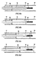
- Fig. 4 shows a catheter 60 which has several components in common with the catheter 10 of Figs. 1 and 2 , and similar components in the catheters 10 and 60 are indicated by the same reference numerals, without further comment or explanation.
- the catheter 60 includes a ramming mechanism that is used to urge the balloon from its first position shown in Fig. 5a to its second position shown in Fig. 5b .
- the ramming mechanism includes a cylindrical flexible cover 56 enclosing at least a portion of the catheter shaft 12.
- the distal end of the flexible cover 56 is attached to an annular ramming plate 57.
- the cover 56 and the ramming plate 57 are slidable along the catheter shaft 12.
- Fig. 6 shows use of the catheter 10 for retrieving an object 50 from a body passageway 52.
- the object 50 may be, for example, a stent that is to be removed from the body.
- the object 50 may be unwanted debris that is to be removed from the body.
- the tip of the catheter shaft 12 is advanced in the passageway 52 with the balloon 18 in its deflated state in its first position, until the catheter tip is close to the object 50, with the balloon in its deflated state.
- the balloon 18 is then inflated ( Fig. 6b ) while remaining in its first position in which the distal end of the balloon 18 is adjacent to the distal end of the catheter tip.
- the balloon 18 is then urged into its second position by means of the ramming mechanism, as explained above ( Fig. 6c ). As the balloon 18 rolls distally over the catheter tip, the object 50 enters the lumen 54 of the balloon 18, and is grasped by the balloon 18 ( Fig. 6c ). The balloon 18 continues to roll over the catheter tip until it has completely enveloped the object 50 as shown in Fig. 6d . The balloon 18 can then be deflated and the catheter removed from the body together with the object 50.
- the system of the present invention may also be used to perform a retrograde ballooning procedure for the combined purpose of removing atheromatous plaque materials and preventing the latrogenic release of said materials into the blood streams, as will be presently described.
- angioplasty is performed by bringing a balloon catheter to the desired operating site, inflating the balloon to a sufficient pressure to allow distension of the arterial wall, thereby expanding and opening the previously blocked or partially-blocked arterial lumen.
- Such a procedure may be not well adapted to certain pathological situations. For example, vulnerable plaques may present with a very thin cap, prone to rupture thereby releasing their lipid core and atheromatous material downstream into the blood flow.
- the catheter system of the present invention permits the use of a new therapeutic sodality in which the operator introduces the non-inflated balloon distal to the lesion to be treated.
- the balloon is then inflated and caused to move proximally with its retrograde, rolling, tank track-like motion by gently pulling the catheter shaft in a proximal direction.
- the arterial lesion may be squeezed up to its proximal shoulder, allowing release of the lipid core and of the atheromateous material into the blood stream, proximal to the inflated balloon.
- the operator gently pushes the catheter shaft (i.e, in a distal direction), causing a forward, rolling, tank track-like motion of the balloon along the catheter shaft causing the debris and atheromateous material to be trapped between the catheter shaft and the balloon (or ⁇ if present ⁇ between the retaining sleeve and balloon or within shaft retention elements, as described hereinabove).
- the operator then deflates the balloon, ensuring complete entrapment of the collected material.
- the method described hereinabove may also be applied in the opposite direction, i.e. the balloon is inflated on the proximal side of the lesion and then rolled distally.
Landscapes
- Health & Medical Sciences (AREA)
- Life Sciences & Earth Sciences (AREA)
- Heart & Thoracic Surgery (AREA)
- Biomedical Technology (AREA)
- Engineering & Computer Science (AREA)
- General Health & Medical Sciences (AREA)
- Animal Behavior & Ethology (AREA)
- Public Health (AREA)
- Veterinary Medicine (AREA)
- Surgery (AREA)
- Vascular Medicine (AREA)
- Nuclear Medicine, Radiotherapy & Molecular Imaging (AREA)
- Medical Informatics (AREA)
- Molecular Biology (AREA)
- Orthopedic Medicine & Surgery (AREA)
- Anesthesiology (AREA)
- Child & Adolescent Psychology (AREA)
- Biophysics (AREA)
- Pulmonology (AREA)
- Hematology (AREA)
- Oral & Maxillofacial Surgery (AREA)
- Transplantation (AREA)
- Cardiology (AREA)
- Media Introduction/Drainage Providing Device (AREA)
- Surgical Instruments (AREA)
- Materials For Medical Uses (AREA)
Applications Claiming Priority (2)
| Application Number | Priority Date | Filing Date | Title |
|---|---|---|---|
| IL16155404A IL161554A0 (en) | 2004-04-22 | 2004-04-22 | Catheter |
| EP05735055A EP1753348B1 (en) | 2004-04-22 | 2005-04-21 | Catheter with balloon |
Related Parent Applications (2)
| Application Number | Title | Priority Date | Filing Date |
|---|---|---|---|
| EP05735055.5 Division | 2005-04-21 | ||
| EP05735055A Division EP1753348B1 (en) | 2004-04-22 | 2005-04-21 | Catheter with balloon |
Publications (2)
| Publication Number | Publication Date |
|---|---|
| EP2298192A1 EP2298192A1 (en) | 2011-03-23 |
| EP2298192B1 true EP2298192B1 (en) | 2012-09-12 |
Family
ID=34074021
Family Applications (2)
| Application Number | Title | Priority Date | Filing Date |
|---|---|---|---|
| EP10169255A Expired - Lifetime EP2298192B1 (en) | 2004-04-22 | 2005-04-21 | Catheter with balloon |
| EP05735055A Expired - Lifetime EP1753348B1 (en) | 2004-04-22 | 2005-04-21 | Catheter with balloon |
Family Applications After (1)
| Application Number | Title | Priority Date | Filing Date |
|---|---|---|---|
| EP05735055A Expired - Lifetime EP1753348B1 (en) | 2004-04-22 | 2005-04-21 | Catheter with balloon |
Country Status (12)
| Country | Link |
|---|---|
| US (2) | US7824370B2 (https=) |
| EP (2) | EP2298192B1 (https=) |
| JP (2) | JP4969441B2 (https=) |
| KR (1) | KR20070011526A (https=) |
| CN (2) | CN101972510B (https=) |
| AT (1) | ATE476923T1 (https=) |
| AU (1) | AU2005235226A1 (https=) |
| CA (1) | CA2563657A1 (https=) |
| DE (1) | DE602005022858D1 (https=) |
| ES (1) | ES2348515T3 (https=) |
| IL (3) | IL161554A0 (https=) |
| WO (1) | WO2005102184A1 (https=) |
Families Citing this family (33)
| Publication number | Priority date | Publication date | Assignee | Title |
|---|---|---|---|---|
| US8556851B2 (en) | 2005-07-05 | 2013-10-15 | Angioslide Ltd. | Balloon catheter |
| US9439662B2 (en) | 2005-07-05 | 2016-09-13 | Angioslide Ltd. | Balloon catheter |
| US8343170B2 (en) | 2005-08-12 | 2013-01-01 | Massicotte J Mathieu | Method and device for extracting objects from the body |
| US8388599B2 (en) * | 2006-05-05 | 2013-03-05 | Abbott Laboratories | Method with balloon catheter having first and second inflatable elements |
| JP2010516351A (ja) * | 2007-01-25 | 2010-05-20 | レベル・スリー・イノベイションズ・プロプライエタリー・リミテッド | 管拡張装置 |
| US20100256600A1 (en) * | 2009-04-04 | 2010-10-07 | Ferrera David A | Neurovascular otw pta balloon catheter and delivery system |
| US8827951B2 (en) | 2008-07-02 | 2014-09-09 | Doron Besser | Balloon catheter system and methods of use thereof |
| US8109985B2 (en) * | 2008-07-23 | 2012-02-07 | Boston Scientific Scimed, Inc. | Occlusion crossing device and method |
| WO2011089599A1 (en) | 2010-01-19 | 2011-07-28 | Angioslide Ltd. | Balloon catheter system and methods of making and use thereof |
| US9227084B2 (en) * | 2011-09-29 | 2016-01-05 | Radiadyne Llc | Universal balloon for brachytherapy applicator |
| CA2860301C (en) * | 2012-01-15 | 2019-04-23 | Triticum Ltd. | Device and method for removing occlusions in a biological vessel |
| US9381326B2 (en) | 2012-06-15 | 2016-07-05 | W. L. Gore & Associates, Inc. | Vascular occlusion and drug delivery devices, systems, and methods |
| JP2016503330A (ja) * | 2012-12-04 | 2016-02-04 | アンジオスライド リミテッド | バルーンカテーテル及びその使用方法 |
| US9693676B2 (en) | 2013-05-10 | 2017-07-04 | J. Mathieu Massicotte | Toroidal balloon-driven vehicle |
| DK3021928T3 (da) * | 2013-07-18 | 2023-01-09 | Univ Maryland | Selvekspanderende kanyle |
| US9480850B2 (en) * | 2013-08-16 | 2016-11-01 | Cardiac Pacemakers, Inc. | Leadless cardiac pacemaker and retrieval device |
| CN104415449B (zh) * | 2013-08-21 | 2019-12-10 | 复旦大学附属肿瘤医院 | 膀胱冲洗防堵塞导尿管 |
| US10213208B2 (en) * | 2014-03-24 | 2019-02-26 | J. Mathieu Massicotte | Toroidal balloon for external or internal compression with unique insertion or removal |
| CN104095668B (zh) * | 2014-07-15 | 2016-08-24 | 中国人民解放军第二军医大学 | 异形球囊式输尿管结石阻挡取出器 |
| US10772647B2 (en) | 2015-01-28 | 2020-09-15 | Triticum Ltd. | Device and method for removing occlusions in a biological vessel |
| CN105919649B (zh) * | 2016-06-15 | 2018-03-23 | 汕头大学医学院第一附属医院 | 一种套叠式血管内异物取出装置 |
| US10460395B2 (en) | 2016-06-30 | 2019-10-29 | Square, Inc. | Graphical user interface for tracking transactions |
| US20180005203A1 (en) * | 2016-06-30 | 2018-01-04 | Square, Inc. | Display notification of information upon payment authorization |
| US10453049B2 (en) | 2016-06-30 | 2019-10-22 | Square, Inc. | Physical, logical separation of balances of funds |
| GB2558930A (en) * | 2017-01-20 | 2018-07-25 | The Flume Catheter Company Ltd | Urinary catheter |
| GB2565843B (en) * | 2017-08-25 | 2019-09-25 | Strait Access Tech Holdings Pty Ltd | Invaginating device |
| US11559673B2 (en) * | 2018-06-22 | 2023-01-24 | Acclarent, Inc. | Multi-balloon instrument for dilating eustachian tube via middle ear |
| US10576248B2 (en) | 2018-07-23 | 2020-03-03 | Crossbay Medical, Inc. | Apparatus and method for everting catheter for uterine access for biopsy and cytology |
| US11756020B1 (en) | 2019-07-31 | 2023-09-12 | Block, Inc. | Gesture and context interpretation for secure interactions |
| CN120959962A (zh) | 2019-10-09 | 2025-11-18 | 克劳斯贝医疗有限公司 | 在子宫腔中输送和放置iud的外翻导管的设备和方法 |
| US12256923B2 (en) | 2020-08-13 | 2025-03-25 | Covidien Lp | Endoluminal robotic systems and methods for suturing |
| US12383352B2 (en) | 2020-08-13 | 2025-08-12 | Covidien Lp | Endoluminal robotic (ELR) systems and methods |
| GB202018856D0 (en) | 2020-11-30 | 2021-01-13 | King S College London | An eversion robot system and method of operating the eversion robot system |
Family Cites Families (73)
| Publication number | Priority date | Publication date | Assignee | Title |
|---|---|---|---|---|
| US4004588A (en) * | 1975-05-21 | 1977-01-25 | Wrightson Nma Limited | Apparatus for flushing ova from cows or mares |
| JPS5431825Y2 (https=) * | 1975-06-30 | 1979-10-04 | ||
| US4271839A (en) | 1979-07-25 | 1981-06-09 | Thomas J. Fogarty | Dilation catheter method and apparatus |
| US4243040A (en) * | 1979-09-17 | 1981-01-06 | Beecher William H | Extracting device for removing objects from human body passages |
| US4597389A (en) | 1982-09-30 | 1986-07-01 | Ibrahim Adel A | Device for removing objects from tubular body passages |
| JPS59502134A (ja) | 1982-10-08 | 1984-12-27 | ハ−ドキャッスル、ディビッド | 体腔への開路装置 |
| US4469100A (en) | 1983-03-14 | 1984-09-04 | Hardwick Charles W | Intussuscepting balloon catheter for stone extraction |
| US4611594A (en) * | 1984-04-11 | 1986-09-16 | Northwestern University | Medical instrument for containment and removal of calculi |
| DE3442736C2 (de) * | 1984-11-23 | 1987-03-05 | Tassilo Dr.med. 7800 Freiburg Bonzel | Dilatationskatheter |
| EP0200668A3 (en) * | 1985-04-25 | 1988-03-09 | FOGARTY, Thomas J. | Apparatus and method for dislodging and removing occlusive objects from body passages |
| JPS63158064A (ja) * | 1986-12-23 | 1988-07-01 | テルモ株式会社 | 血管拡張カテ−テル |
| US4748982A (en) * | 1987-01-06 | 1988-06-07 | Advanced Cardiovascular Systems, Inc. | Reinforced balloon dilatation catheter with slitted exchange sleeve and method |
| USRE34633E (en) * | 1987-11-13 | 1994-06-07 | Cook Incorporated | Balloon guide |
| US5019041A (en) * | 1988-03-08 | 1991-05-28 | Scimed Life Systems, Inc. | Balloon catheter inflation device |
| EP0359489A2 (en) | 1988-09-15 | 1990-03-21 | Baxter International Inc. | Everting balloon catheter with anchor annulus and balloon for same |
| US4946440A (en) * | 1988-10-05 | 1990-08-07 | Hall John E | Evertible membrane catheter and method of use |
| EP0638327B1 (en) | 1989-01-30 | 2008-08-20 | C.R. Bard, Inc. | Rapidly exchangeable coronary catheter |
| US5074845A (en) * | 1989-07-18 | 1991-12-24 | Baxter International Inc. | Catheter with heat-fused balloon with waist |
| US5092839A (en) * | 1989-09-29 | 1992-03-03 | Kipperman Robert M | Coronary thrombectomy |
| US5109830A (en) | 1990-04-10 | 1992-05-05 | Candela Laser Corporation | Apparatus for navigation of body cavities |
| CA2048120A1 (en) * | 1990-08-06 | 1992-02-07 | William J. Drasler | Thrombectomy method and device |
| US5254091A (en) * | 1991-01-08 | 1993-10-19 | Applied Medical Resources Corporation | Low profile balloon catheter and method for making same |
| US5307814A (en) * | 1991-09-17 | 1994-05-03 | Medrad, Inc. | Externally moveable intracavity probe for MRI imaging and spectroscopy |
| AU6098494A (en) | 1993-01-29 | 1994-08-15 | United States Of America, Represented By The Secretary, Department Of Health And Human Services, The | Multifinger topocatheter tip for multilumen catheter for angioplasty and manipulation |
| US5630822A (en) * | 1993-07-02 | 1997-05-20 | General Surgical Innovations, Inc | Laparoscopic tissue removal device |
| US5445646A (en) * | 1993-10-22 | 1995-08-29 | Scimed Lifesystems, Inc. | Single layer hydraulic sheath stent delivery apparatus and method |
| US6120523A (en) * | 1994-02-24 | 2000-09-19 | Radiance Medical Systems, Inc. | Focalized intraluminal balloons |
| US5470314A (en) * | 1994-07-22 | 1995-11-28 | Walinsky; Paul | Perfusion balloon catheter with differential compliance |
| US5632754A (en) * | 1994-12-23 | 1997-05-27 | Devices For Vascular Intervention | Universal catheter with interchangeable work element |
| US5534007A (en) * | 1995-05-18 | 1996-07-09 | Scimed Life Systems, Inc. | Stent deployment catheter with collapsible sheath |
| US5865801A (en) * | 1995-07-18 | 1999-02-02 | Houser; Russell A. | Multiple compartmented balloon catheter with external pressure sensing |
| US6004341A (en) * | 1996-12-05 | 1999-12-21 | Loma Linda University Medical Center | Vascular wound closure device |
| CA2211249C (en) * | 1996-07-24 | 2007-07-17 | Cordis Corporation | Balloon catheter and methods of use |
| US5941895A (en) | 1996-09-04 | 1999-08-24 | Hemodynamics, Inc. | Cardiovascular stent and retrieval apparatus |
| AU5621198A (en) | 1996-12-30 | 1998-07-31 | Imagyn Medical Technologies, Inc. | Expandable access device and method of constructing and using same |
| US6974469B2 (en) * | 1997-03-06 | 2005-12-13 | Scimed Life Systems, Inc. | Distal protection device and method |
| WO1999016499A1 (en) * | 1997-10-01 | 1999-04-08 | Boston Scientific Corporation | Dilation systems and related methods |
| US6695810B2 (en) * | 1997-11-21 | 2004-02-24 | Advanced Interventional Technologies, Inc. | Endolumenal aortic isolation assembly and method |
| US6179827B1 (en) * | 1998-03-16 | 2001-01-30 | Chase Medical | Catheter having integral expandable/collapsible lumen |
| US6383195B1 (en) * | 1998-04-13 | 2002-05-07 | Endoline, Inc. | Laparoscopic specimen removal apparatus |
| US6007557A (en) * | 1998-04-29 | 1999-12-28 | Embol-X, Inc. | Adjustable blood filtration system |
| JP2000005189A (ja) * | 1998-06-24 | 2000-01-11 | Terumo Corp | 異物除去用カテーテル |
| US6287506B1 (en) | 1998-07-09 | 2001-09-11 | Schneider (Usa) Inc. | Method for reducing dilation balloon cone stiffness |
| US6059813A (en) | 1998-11-06 | 2000-05-09 | Scimed Life Systems, Inc. | Rolling membrane stent delivery system |
| US6544278B1 (en) * | 1998-11-06 | 2003-04-08 | Scimed Life Systems, Inc. | Rolling membrane stent delivery system |
| US6129706A (en) * | 1998-12-10 | 2000-10-10 | Janacek; Jaroslav | Corrugated catheter balloon |
| US6264630B1 (en) | 1998-12-23 | 2001-07-24 | Scimed Life Systems, Inc. | Balloon catheter having an oscillating tip configuration |
| US6022359A (en) * | 1999-01-13 | 2000-02-08 | Frantzen; John J. | Stent delivery system featuring a flexible balloon |
| US6280412B1 (en) * | 1999-06-17 | 2001-08-28 | Scimed Life Systems, Inc. | Stent securement by balloon modification |
| JP2001009037A (ja) | 1999-06-25 | 2001-01-16 | Terumo Corp | 狭窄部拡張用バルーンおよびバルーンカテーテル |
| US6602263B1 (en) * | 1999-11-30 | 2003-08-05 | St. Jude Medical Atg, Inc. | Medical grafting methods and apparatus |
| US7201770B2 (en) * | 2000-03-21 | 2007-04-10 | Cordis Corporation | Everting balloon stent delivery system having tapered leading edge |
| AUPQ641400A0 (en) * | 2000-03-23 | 2000-04-15 | Kleiner, Daniel E. | A device incorporating a hollow member for being positioned along a body cavity of a patient and method of positioning same |
| US20040073243A1 (en) * | 2000-06-29 | 2004-04-15 | Concentric Medical, Inc., A Delaware Corporation | Systems, methods and devices for removing obstructions from a blood vessel |
| US6607552B1 (en) * | 2000-09-18 | 2003-08-19 | Scimed Life Systems, Inc. | Rolling socks |
| ES2370109T3 (es) | 2001-01-09 | 2011-12-12 | Microvention, Inc. | Catéteres de embolectomía. |
| US7226464B2 (en) * | 2001-03-01 | 2007-06-05 | Scimed Life Systems, Inc. | Intravascular filter retrieval device having an actuatable dilator tip |
| US7604612B2 (en) | 2001-05-01 | 2009-10-20 | St. Jude Medical, Cardiology Division, Inc. | Emboli protection devices and related methods of use |
| US20020177870A1 (en) * | 2001-05-25 | 2002-11-28 | Ivan Sepetka | Single lumen balloon catheter |
| JP4460289B2 (ja) * | 2001-08-23 | 2010-05-12 | シー. ガム、ダレル | カテーテルアセンブリ |
| CA2457189C (en) * | 2001-09-28 | 2011-08-09 | Boston Scientific Limited | Medical devices comprising nanomaterials and therapeutic methods utilizing the same |
| US7189250B2 (en) * | 2002-01-10 | 2007-03-13 | Scimed Life Systems, Inc. | Aspirating balloon catheter for treating vulnerable plaque |
| US20030176884A1 (en) * | 2002-03-12 | 2003-09-18 | Marwane Berrada | Everted filter device |
| JP2004097807A (ja) * | 2002-08-20 | 2004-04-02 | Nipro Corp | 血栓捕捉カテーテル |
| US6808524B2 (en) * | 2002-09-16 | 2004-10-26 | Prorhythm, Inc. | Balloon alignment and collapsing system |
| US20050261719A1 (en) * | 2002-11-25 | 2005-11-24 | Israel Chermoni | Catheter and method of its use |
| JP4289919B2 (ja) | 2003-05-06 | 2009-07-01 | 朝日インテック株式会社 | 薬液注入装置 |
| WO2005000130A1 (en) | 2003-06-11 | 2005-01-06 | Concentric Medical, Inc. | Systems, methods and devices for removing obstructions from a blood vessel |
| US20050004553A1 (en) * | 2003-07-02 | 2005-01-06 | Medtronic Ave, Inc. | Sheath catheter having variable over-the-wire length and methods of use |
| US20050085826A1 (en) * | 2003-10-21 | 2005-04-21 | Scimed Life Systems, Inc. | Unfolding balloon catheter for proximal embolus protection |
| US7491213B2 (en) * | 2004-01-13 | 2009-02-17 | Boston Scientific Scimed, Inc. | Catheter shaft having distal support |
| US20050267492A1 (en) | 2004-05-12 | 2005-12-01 | Philippe Poncet | Surgical instrument for specimen retrieval |
| US7972351B2 (en) * | 2004-07-13 | 2011-07-05 | Boston Scientific Scimed, Inc. | Balloon folding design and method and apparatus for making balloons |
-
2004
- 2004-04-22 IL IL16155404A patent/IL161554A0/xx unknown
-
2005
- 2005-04-21 AU AU2005235226A patent/AU2005235226A1/en not_active Abandoned
- 2005-04-21 CN CN2010102249449A patent/CN101972510B/zh not_active Expired - Fee Related
- 2005-04-21 DE DE602005022858T patent/DE602005022858D1/de not_active Expired - Lifetime
- 2005-04-21 US US11/587,179 patent/US7824370B2/en not_active Expired - Fee Related
- 2005-04-21 JP JP2007509059A patent/JP4969441B2/ja not_active Expired - Fee Related
- 2005-04-21 CA CA002563657A patent/CA2563657A1/en not_active Abandoned
- 2005-04-21 KR KR1020067024395A patent/KR20070011526A/ko not_active Withdrawn
- 2005-04-21 CN CN2005800207330A patent/CN1972636B/zh not_active Expired - Fee Related
- 2005-04-21 AT AT05735055T patent/ATE476923T1/de not_active IP Right Cessation
- 2005-04-21 EP EP10169255A patent/EP2298192B1/en not_active Expired - Lifetime
- 2005-04-21 ES ES05735055T patent/ES2348515T3/es not_active Expired - Lifetime
- 2005-04-21 EP EP05735055A patent/EP1753348B1/en not_active Expired - Lifetime
- 2005-04-21 WO PCT/IL2005/000420 patent/WO2005102184A1/en not_active Ceased
-
2006
- 2006-10-19 IL IL178738A patent/IL178738A0/en unknown
-
2010
- 2010-10-10 US US12/901,535 patent/US8388574B2/en not_active Expired - Fee Related
-
2011
- 2011-02-02 IL IL211022A patent/IL211022A0/en unknown
- 2011-06-14 JP JP2011132174A patent/JP2011200689A/ja active Pending
Also Published As
| Publication number | Publication date |
|---|---|
| IL178738A0 (en) | 2007-02-11 |
| US20080051706A1 (en) | 2008-02-28 |
| KR20070011526A (ko) | 2007-01-24 |
| CA2563657A1 (en) | 2005-11-03 |
| CN101972510A (zh) | 2011-02-16 |
| US20110040365A1 (en) | 2011-02-17 |
| AU2005235226A1 (en) | 2005-11-03 |
| US7824370B2 (en) | 2010-11-02 |
| EP2298192A1 (en) | 2011-03-23 |
| JP2007533394A (ja) | 2007-11-22 |
| IL211022A0 (en) | 2011-04-28 |
| US8388574B2 (en) | 2013-03-05 |
| CN101972510B (zh) | 2013-06-12 |
| CN1972636A (zh) | 2007-05-30 |
| IL161554A0 (en) | 2004-09-27 |
| EP1753348B1 (en) | 2010-08-11 |
| WO2005102184A1 (en) | 2005-11-03 |
| JP2011200689A (ja) | 2011-10-13 |
| ATE476923T1 (de) | 2010-08-15 |
| ES2348515T3 (es) | 2010-12-07 |
| JP4969441B2 (ja) | 2012-07-04 |
| DE602005022858D1 (de) | 2010-09-23 |
| CN1972636B (zh) | 2010-09-01 |
| EP1753348A1 (en) | 2007-02-21 |
Similar Documents
| Publication | Publication Date | Title |
|---|---|---|
| EP2298192B1 (en) | Catheter with balloon | |
| ES2324915T3 (es) | Cateter de balon desplegable para proteccion proximal del embolo. | |
| ES2792100T3 (es) | Aparatos de trombectomía mecánica para retención de coágulos | |
| AU720376B2 (en) | Incisor-dilator with tapered balloon | |
| CA2703345C (en) | Balloons and balloon catheter systems for treating vascular occlusions | |
| US5458615A (en) | Stent delivery system | |
| US7722634B2 (en) | Medical device and method of intravenous filtration | |
| US9980839B2 (en) | Balloon catheter for multiple adjustable stent deployment | |
| JP2956966B2 (ja) | カテーテルアセンブリおよびステント供給システム | |
| EP2181728B1 (en) | Balloon Catheter | |
| JPH09501852A (ja) | 偏心状のバルーンを備えた拡張カテーテル | |
| JP2004510486A (ja) | フィルタ送達および回収装置 | |
| CN102711897A (zh) | 囊导管及其使用方法 | |
| JP2011526530A (ja) | 蛇腹式バルーンカテーテルシステム及びその使用方法 | |
| WO2000013739A1 (en) | Stent deployment system and method of use | |
| ES2352568T3 (es) | Catéter con globo. |
Legal Events
| Date | Code | Title | Description |
|---|---|---|---|
| PUAI | Public reference made under article 153(3) epc to a published international application that has entered the european phase |
Free format text: ORIGINAL CODE: 0009012 |
|
| AC | Divisional application: reference to earlier application |
Ref document number: 1753348 Country of ref document: EP Kind code of ref document: P |
|
| AK | Designated contracting states |
Kind code of ref document: A1 Designated state(s): AT BE BG CH CY CZ DE DK EE ES FI FR GB GR HU IE IS IT LI LT LU MC NL PL PT RO SE SI SK TR |
|
| 17P | Request for examination filed |
Effective date: 20110923 |
|
| GRAP | Despatch of communication of intention to grant a patent |
Free format text: ORIGINAL CODE: EPIDOSNIGR1 |
|
| GRAS | Grant fee paid |
Free format text: ORIGINAL CODE: EPIDOSNIGR3 |
|
| GRAA | (expected) grant |
Free format text: ORIGINAL CODE: 0009210 |
|
| AC | Divisional application: reference to earlier application |
Ref document number: 1753348 Country of ref document: EP Kind code of ref document: P |
|
| AK | Designated contracting states |
Kind code of ref document: B1 Designated state(s): AT BE BG CH CY CZ DE DK EE ES FI FR GB GR HU IE IS IT LI LT LU MC NL PL PT RO SE SI SK TR |
|
| REG | Reference to a national code |
Ref country code: GB Ref legal event code: FG4D |
|
| REG | Reference to a national code |
Ref country code: CH Ref legal event code: EP |
|
| REG | Reference to a national code |
Ref country code: AT Ref legal event code: REF Ref document number: 574662 Country of ref document: AT Kind code of ref document: T Effective date: 20120915 |
|
| REG | Reference to a national code |
Ref country code: IE Ref legal event code: FG4D |
|
| REG | Reference to a national code |
Ref country code: DE Ref legal event code: R096 Ref document number: 602005036151 Country of ref document: DE Effective date: 20121108 |
|
| PG25 | Lapsed in a contracting state [announced via postgrant information from national office to epo] |
Ref country code: FI Free format text: LAPSE BECAUSE OF FAILURE TO SUBMIT A TRANSLATION OF THE DESCRIPTION OR TO PAY THE FEE WITHIN THE PRESCRIBED TIME-LIMIT Effective date: 20120912 Ref country code: LT Free format text: LAPSE BECAUSE OF FAILURE TO SUBMIT A TRANSLATION OF THE DESCRIPTION OR TO PAY THE FEE WITHIN THE PRESCRIBED TIME-LIMIT Effective date: 20120912 |
|
| REG | Reference to a national code |
Ref country code: NL Ref legal event code: VDEP Effective date: 20120912 |
|
| REG | Reference to a national code |
Ref country code: AT Ref legal event code: MK05 Ref document number: 574662 Country of ref document: AT Kind code of ref document: T Effective date: 20120912 |
|
| REG | Reference to a national code |
Ref country code: LT Ref legal event code: MG4D Effective date: 20120912 |
|
| PG25 | Lapsed in a contracting state [announced via postgrant information from national office to epo] |
Ref country code: GR Free format text: LAPSE BECAUSE OF FAILURE TO SUBMIT A TRANSLATION OF THE DESCRIPTION OR TO PAY THE FEE WITHIN THE PRESCRIBED TIME-LIMIT Effective date: 20121213 Ref country code: SE Free format text: LAPSE BECAUSE OF FAILURE TO SUBMIT A TRANSLATION OF THE DESCRIPTION OR TO PAY THE FEE WITHIN THE PRESCRIBED TIME-LIMIT Effective date: 20120912 Ref country code: SI Free format text: LAPSE BECAUSE OF FAILURE TO SUBMIT A TRANSLATION OF THE DESCRIPTION OR TO PAY THE FEE WITHIN THE PRESCRIBED TIME-LIMIT Effective date: 20120912 |
|
| PG25 | Lapsed in a contracting state [announced via postgrant information from national office to epo] |
Ref country code: NL Free format text: LAPSE BECAUSE OF FAILURE TO SUBMIT A TRANSLATION OF THE DESCRIPTION OR TO PAY THE FEE WITHIN THE PRESCRIBED TIME-LIMIT Effective date: 20120912 Ref country code: BE Free format text: LAPSE BECAUSE OF FAILURE TO SUBMIT A TRANSLATION OF THE DESCRIPTION OR TO PAY THE FEE WITHIN THE PRESCRIBED TIME-LIMIT Effective date: 20120912 Ref country code: CZ Free format text: LAPSE BECAUSE OF FAILURE TO SUBMIT A TRANSLATION OF THE DESCRIPTION OR TO PAY THE FEE WITHIN THE PRESCRIBED TIME-LIMIT Effective date: 20120912 Ref country code: ES Free format text: LAPSE BECAUSE OF FAILURE TO SUBMIT A TRANSLATION OF THE DESCRIPTION OR TO PAY THE FEE WITHIN THE PRESCRIBED TIME-LIMIT Effective date: 20121223 Ref country code: IS Free format text: LAPSE BECAUSE OF FAILURE TO SUBMIT A TRANSLATION OF THE DESCRIPTION OR TO PAY THE FEE WITHIN THE PRESCRIBED TIME-LIMIT Effective date: 20130112 Ref country code: RO Free format text: LAPSE BECAUSE OF FAILURE TO SUBMIT A TRANSLATION OF THE DESCRIPTION OR TO PAY THE FEE WITHIN THE PRESCRIBED TIME-LIMIT Effective date: 20120912 Ref country code: EE Free format text: LAPSE BECAUSE OF FAILURE TO SUBMIT A TRANSLATION OF THE DESCRIPTION OR TO PAY THE FEE WITHIN THE PRESCRIBED TIME-LIMIT Effective date: 20120912 |
|
| PG25 | Lapsed in a contracting state [announced via postgrant information from national office to epo] |
Ref country code: PL Free format text: LAPSE BECAUSE OF FAILURE TO SUBMIT A TRANSLATION OF THE DESCRIPTION OR TO PAY THE FEE WITHIN THE PRESCRIBED TIME-LIMIT Effective date: 20120912 Ref country code: SK Free format text: LAPSE BECAUSE OF FAILURE TO SUBMIT A TRANSLATION OF THE DESCRIPTION OR TO PAY THE FEE WITHIN THE PRESCRIBED TIME-LIMIT Effective date: 20120912 Ref country code: PT Free format text: LAPSE BECAUSE OF FAILURE TO SUBMIT A TRANSLATION OF THE DESCRIPTION OR TO PAY THE FEE WITHIN THE PRESCRIBED TIME-LIMIT Effective date: 20130114 |
|
| PG25 | Lapsed in a contracting state [announced via postgrant information from national office to epo] |
Ref country code: AT Free format text: LAPSE BECAUSE OF FAILURE TO SUBMIT A TRANSLATION OF THE DESCRIPTION OR TO PAY THE FEE WITHIN THE PRESCRIBED TIME-LIMIT Effective date: 20120912 |
|
| PLBE | No opposition filed within time limit |
Free format text: ORIGINAL CODE: 0009261 |
|
| STAA | Information on the status of an ep patent application or granted ep patent |
Free format text: STATUS: NO OPPOSITION FILED WITHIN TIME LIMIT |
|
| PG25 | Lapsed in a contracting state [announced via postgrant information from national office to epo] |
Ref country code: DK Free format text: LAPSE BECAUSE OF FAILURE TO SUBMIT A TRANSLATION OF THE DESCRIPTION OR TO PAY THE FEE WITHIN THE PRESCRIBED TIME-LIMIT Effective date: 20120912 Ref country code: BG Free format text: LAPSE BECAUSE OF FAILURE TO SUBMIT A TRANSLATION OF THE DESCRIPTION OR TO PAY THE FEE WITHIN THE PRESCRIBED TIME-LIMIT Effective date: 20121212 |
|
| 26N | No opposition filed |
Effective date: 20130613 |
|
| REG | Reference to a national code |
Ref country code: DE Ref legal event code: R097 Ref document number: 602005036151 Country of ref document: DE Effective date: 20130613 |
|
| PG25 | Lapsed in a contracting state [announced via postgrant information from national office to epo] |
Ref country code: MC Free format text: LAPSE BECAUSE OF FAILURE TO SUBMIT A TRANSLATION OF THE DESCRIPTION OR TO PAY THE FEE WITHIN THE PRESCRIBED TIME-LIMIT Effective date: 20120912 Ref country code: CY Free format text: LAPSE BECAUSE OF FAILURE TO SUBMIT A TRANSLATION OF THE DESCRIPTION OR TO PAY THE FEE WITHIN THE PRESCRIBED TIME-LIMIT Effective date: 20120912 |
|
| REG | Reference to a national code |
Ref country code: CH Ref legal event code: PL |
|
| REG | Reference to a national code |
Ref country code: IE Ref legal event code: MM4A |
|
| PG25 | Lapsed in a contracting state [announced via postgrant information from national office to epo] |
Ref country code: CH Free format text: LAPSE BECAUSE OF NON-PAYMENT OF DUE FEES Effective date: 20130430 Ref country code: LI Free format text: LAPSE BECAUSE OF NON-PAYMENT OF DUE FEES Effective date: 20130430 |
|
| PG25 | Lapsed in a contracting state [announced via postgrant information from national office to epo] |
Ref country code: IE Free format text: LAPSE BECAUSE OF NON-PAYMENT OF DUE FEES Effective date: 20130421 |
|
| PG25 | Lapsed in a contracting state [announced via postgrant information from national office to epo] |
Ref country code: TR Free format text: LAPSE BECAUSE OF FAILURE TO SUBMIT A TRANSLATION OF THE DESCRIPTION OR TO PAY THE FEE WITHIN THE PRESCRIBED TIME-LIMIT Effective date: 20120912 |
|
| PG25 | Lapsed in a contracting state [announced via postgrant information from national office to epo] |
Ref country code: LU Free format text: LAPSE BECAUSE OF NON-PAYMENT OF DUE FEES Effective date: 20130421 Ref country code: HU Free format text: LAPSE BECAUSE OF FAILURE TO SUBMIT A TRANSLATION OF THE DESCRIPTION OR TO PAY THE FEE WITHIN THE PRESCRIBED TIME-LIMIT; INVALID AB INITIO Effective date: 20050421 |
|
| REG | Reference to a national code |
Ref country code: FR Ref legal event code: PLFP Year of fee payment: 12 |
|
| REG | Reference to a national code |
Ref country code: FR Ref legal event code: PLFP Year of fee payment: 13 |
|
| REG | Reference to a national code |
Ref country code: FR Ref legal event code: PLFP Year of fee payment: 14 |
|
| PGFP | Annual fee paid to national office [announced via postgrant information from national office to epo] |
Ref country code: DE Payment date: 20180420 Year of fee payment: 14 |
|
| PGFP | Annual fee paid to national office [announced via postgrant information from national office to epo] |
Ref country code: FR Payment date: 20180420 Year of fee payment: 14 Ref country code: IT Payment date: 20180423 Year of fee payment: 14 |
|
| PGFP | Annual fee paid to national office [announced via postgrant information from national office to epo] |
Ref country code: GB Payment date: 20180418 Year of fee payment: 14 |
|
| REG | Reference to a national code |
Ref country code: DE Ref legal event code: R119 Ref document number: 602005036151 Country of ref document: DE |
|
| GBPC | Gb: european patent ceased through non-payment of renewal fee |
Effective date: 20190421 |
|
| PG25 | Lapsed in a contracting state [announced via postgrant information from national office to epo] |
Ref country code: GB Free format text: LAPSE BECAUSE OF NON-PAYMENT OF DUE FEES Effective date: 20190421 Ref country code: DE Free format text: LAPSE BECAUSE OF NON-PAYMENT OF DUE FEES Effective date: 20191101 |
|
| PG25 | Lapsed in a contracting state [announced via postgrant information from national office to epo] |
Ref country code: FR Free format text: LAPSE BECAUSE OF NON-PAYMENT OF DUE FEES Effective date: 20190430 |
|
| PG25 | Lapsed in a contracting state [announced via postgrant information from national office to epo] |
Ref country code: IT Free format text: LAPSE BECAUSE OF NON-PAYMENT OF DUE FEES Effective date: 20190421 |