EP2298058B1 - Aufsatzeinstellverbindung zur Nivellierung eines Mähwerks und Fahrzeug - Google Patents
Aufsatzeinstellverbindung zur Nivellierung eines Mähwerks und Fahrzeug Download PDFInfo
- Publication number
- EP2298058B1 EP2298058B1 EP10175160A EP10175160A EP2298058B1 EP 2298058 B1 EP2298058 B1 EP 2298058B1 EP 10175160 A EP10175160 A EP 10175160A EP 10175160 A EP10175160 A EP 10175160A EP 2298058 B1 EP2298058 B1 EP 2298058B1
- Authority
- EP
- European Patent Office
- Prior art keywords
- deck
- lift
- mower deck
- fender
- mower
- Prior art date
- Legal status (The legal status is an assumption and is not a legal conclusion. Google has not performed a legal analysis and makes no representation as to the accuracy of the status listed.)
- Active
Links
Images


Classifications
-
- A—HUMAN NECESSITIES
- A01—AGRICULTURE; FORESTRY; ANIMAL HUSBANDRY; HUNTING; TRAPPING; FISHING
- A01D—HARVESTING; MOWING
- A01D34/00—Mowers; Mowing apparatus of harvesters
- A01D34/01—Mowers; Mowing apparatus of harvesters characterised by features relating to the type of cutting apparatus
- A01D34/412—Mowers; Mowing apparatus of harvesters characterised by features relating to the type of cutting apparatus having rotating cutters
- A01D34/63—Mowers; Mowing apparatus of harvesters characterised by features relating to the type of cutting apparatus having rotating cutters having cutters rotating about a vertical axis
- A01D34/74—Cutting-height adjustment
Definitions
- This invention relates to mower decks suspended from lawn and garden tractors and other grass mowing machines, and more specifically to a linkage that may be used to properly level and align a mower deck at a specified cutting height and a vehicle.
- a mower deck may be suspended from a lawn and garden tractor or other vehicle, or "floated” on wheels attached to the mower deck.
- the mower deck may cover one or more rotary cutting blades.
- the mower deck and blades should be in proper alignment relative to the mowing vehicle at all cutting heights.
- the mower deck should be properly aligned so that each rotary cutting blade is level side-to-side, and has a slight forward angle or "rake.”
- Proper alignment of the mower deck helps achieve better cut quality, prevents grass frazzling, provides better grass dispersal, better bagging results, and reduces the power required to run the engine.
- the mower deck should be calibrated so that the blades are at the cutting height specified by the mower deck height control knob or lever.
- US2004/0154278A1 shows a mid-mount mower having a front frame unit including a pair of right and left front longitudinal frames, a first cross frame interconnecting the front longitudinal frames in forward positions thereof longitudinally of the vehicle body, and a second cross frame interconnecting the front longitudinal frames in rearward positions thereof longitudinally of the vehicle body, the front frame unit supporting the front wheel unit and also supporting a lift mechanism for vertically movably suspending the mower unit; a rear frame unit including a pair of right and left rear longitudinal frames, the rear frame unit being connected to the front frame unit; and a rear wheel drive unit interconnecting the rear longitudinal frames.
- measurements can be taken from a hard, level floor or ground surface under the vehicle up to the tip of a rotary cutting blade.
- the blades may be manually rotated to a position parallel to the vehicle axle and measurements are taken from the ground up to the left and right outside blade tips.
- the blades may be considered level side-to-side if the left and right measurements are within about 0,3175 cm (1/8 inch) of each other.
- the blades are rotated to point straight forward and backward, and measurements are taken from the ground up to the front and rear blade tips.
- the blades are considered properly aligned front-to-rear if the front blade tip is about 0,3175 cm (1/8 inch) to about 1,27 cm (1 ⁇ 2 inch) lower than the rear blade tip. This may be referred to as "rake.”
- one or more adjustments may be made on the linkages between the mower deck and vehicle frame. For example, to level the mower deck side-to-side, a nut or other connector on the left-hand lift link may be turned to raise or lower the left side of the mower deck. Similarly, to properly align the mower deck front-to-rear, yokes or other connectors between the front of the mower deck and vehicle frame may be adjusted in either direction to lift or lower the front of the mower deck.
- the linkages may include threaded hangers, cams, or slotted mounting brackets attaching the deck to the vehicle frame. Leveling and rake adjustment may be repeated until the height of the cutting blades corresponds to the cutting height designated on the mower deck height control knob or lever.
- a convenient and simple adjustment mechanism is needed for leveling a mower deck.
- An adjustment linkage is needed that reduces, minimizes or eliminates the necessity of reaching around the mounting and drive components on a mower deck. It is therefore the object of the present invention to comply with one, some or all of these needs.
- a top adjusting linkage for leveling a mower deck comprises a deck lift pedal connected to a pivotable lift arm for raising and lowering the mower deck, a draft arm pivotably attached to the mower deck, and a lift rod connecting the lift arm to the draft arm and having an upper end that is engageable to change the spacing between the lift arm and the draft arm.
- a fender deck includes an access opening through which the engageable upper end of the lift rod may be accessed by the operator.
- a top adjusting linkage for leveling a mower deck may comprise a fender deck positioned over the mower deck and having a pair of footrests, a pair of fenders and an operator station for mounting an operator seat; access openings through the fender deck adjacent each footrest; and a pair of lift rods with lower ends connected to draft arms supporting the mower deck and upper ends connected to pivotable lift arms that raise and lower the mower deck; the upper ends under the fender deck and being engageable by inserting a tool from above the fender deck through the access openings to change the spacing between the draft arms and lift arms.
- the top adjusting linkage may further comprise a pair of frame rails under the fender deck to which the lift arms are pivotably mounted.
- the top adjusting linkage may further comprising a sleeve pivotably mounted to each of the lift arms, the upper ends of the lift rods extending through the sleeves.
- the lift rod may be pivotably connected between the lift arm and the draft arm.
- the lower end of the lift rod may be threaded to a lift link pivotably mounted to the draft arm.
- the upper end of the lift rod may be inserted through a lift link pivotably mounted to the lift arm.
- the top adjusting linkage of claim may further comprise a removable plug in the access opening.
- Fig. 1 shows lawn and garden tractor 10 having mower deck 11 suspended from the vehicle between the front and rear wheels.
- the mower deck may be under the longitudinal frame rails 12.
- the lawn and garden tractor may include fender deck 13 mounted to the frame.
- the fender deck may be a one piece molded plastic shell, or a composite or sheet metal structure.
- the fender deck may include left and right footrests 14, fenders 15, and an operator station where seat 16 may be positioned and mounted.
- the mower deck may be suspended from the frame rails with a four bar linkage.
- the mower deck may cover one or more rotary cutting blades on generally vertical shafts driven by an engine drive shaft and a belt and pulley arrangement.
- the mower deck may have anti-scalp wheels. The anti-scalp wheels may be less than about one inch above the ground surface when mowing.
- the operator may use deck lift pedal 18 to raise and lower the mower deck between a mowing position and a transport position.
- the deck lift pedal may be mounted on pivot axis 19 on plate 20 secured to or adjacent frame rail 12.
- Pedal connecting rod 21 may be pivotably mounted between deck lift pedal 18 and lift arm 22.
- a pair of lift arms 22 may be mounted on lift shaft 23 which extends laterally across the vehicle frame between the pair of frame rails.
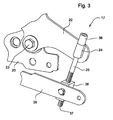
- top adjusting mower linkage 17 includes lift rod 25 that is generally vertically aligned and connects each lift arm 22 to a draft arm 26.
- the upper end 27 of lift rod 25 may be pivotably fastened to the lift arm, and the lower end 28 may be pivotably fastened to the draft arm.
- the upper end 27 of the lift rod may be pivotably fastened to the lift arm using lift link 24.
- Lift link 24 may be a cast sleeve that is pivotably mounted to the outer end of the lift arm, and the upper end of the lift rod may be inserted through the lift link.
- the lower end 28 of the lift rod may be inserted through an opening in the draft arm adjacent the end of the draft arm connected to draft tower 30, and fastened with a washer and clip.
- Each of the upper and lower ends of the lift rod can pivot on axes that are parallel to the lift shaft.
- the upper end of the lift rod, or an adjustment nut on the upper end of the lift rod may be engaged with a tool to change the effective length of lift rod 25.
- An adjustment may be performed to increase or decrease the spacing between each lift arm 22 and draft arm 26.
- An operator may perform this adjustment to align and level the mower deck by accessing the upper end of the lift rod from above the mower deck and fender deck.
- An adjustment tool may be inserted through an access opening 32 in the fender deck to engage the upper end of the lift rod, or an adjustment nut threaded thereto.
- adjusting nut 29 may be threaded to the upper end of each lift rod.
- the adjustment nut may have a hex head that the operator may access and rotate with a socket wrench extending through access opening 32 in the fender deck.
- the upper end of the lift rod is provided with cap screw 36 that may be rotated with an Allen wrench inserted through opening 32.
- the lower end 37 of the lift rod may be externally threaded through internally threaded lift link 38 that is pivotaby mounted to draft arm 26.
- An operator may perform adjustments to align and level the mower deck by inserting a tool through access opening 32 through the fender deck directly above the upper end of the lift rod.
- Each access opening 32 in the fender deck may be at or adjacent each footrest 14.
- Removable plug 34 may cover the opening when not in use.
- guide sleeve 35 may be attached to the fender deck to extend downwardly from the opening and help guide the adjustment tool into engagement with the adjusting nut or upper end of the lift rod.
Landscapes
- Life Sciences & Earth Sciences (AREA)
- Environmental Sciences (AREA)
- Harvester Elements (AREA)
Claims (3)
- Fahrzeug (10), vorzugsweise Rasen- und Gartentraktor, umfassend ein Aufsatzeinstellgestänge zur Nivellierung eines Mähwerks (11), ein Kotflügeldeck (13), das über dem Mähwerk (11) positioniert ist und ein Paar Fußstützen (14) aufweist, ein Paar Kotflügel (15) und eine Bedienerstation zur Montage eines Bedienersitzes (16); gekennzeichnet durch Zugangsöffnungen (32) durch das Kotflügeldeck (13) neben jeder Fußstütze (14) und ein Paar Hubstangen (25) mit unteren Enden (28), die mit das Mähwerk (11) stützenden Zugarmen verbunden sind, und oberen Enden (27), die mit schwenkbaren Hubarmen (22) verbunden sind, die das Mähwerk (11) anheben und absenken; wobei sich die oberen Enden (27) unter dem Kotflügeldeck (13) befinden und durch Einführen eines Werkzeugs von oberhalb des Kotflügeldecks (13) durch die Zugangsöffnungen (32) in Eingriff gebracht werden können, um den Abstand zwischen den Zugarmen (26) und den Hubarmen (22) zu ändern.
- Fahrzeug nach Anspruch 1, gekennzeichnet durch ein Paar Rahmenträger (12) unter dem Kotflügeldeck (13), an denen die Hubarme (22) schwenkbar angebracht sind.
- Fahrzeug nach Anspruch 1 oder 2, gekennzeichnet durch eine Hülse, die schwenkbar an jedem der Hubarme (22) angebracht ist, wobei sich die oberen Enden der Hubstangen (25) durch die Hülsen erstrecken.
Applications Claiming Priority (1)
| Application Number | Priority Date | Filing Date | Title |
|---|---|---|---|
| US12/556,251 US7861502B1 (en) | 2009-09-09 | 2009-09-09 | Top adjusting linkage for leveling a mower deck |
Publications (2)
| Publication Number | Publication Date |
|---|---|
| EP2298058A1 EP2298058A1 (de) | 2011-03-23 |
| EP2298058B1 true EP2298058B1 (de) | 2012-11-14 |
Family
ID=43384840
Family Applications (1)
| Application Number | Title | Priority Date | Filing Date |
|---|---|---|---|
| EP10175160A Active EP2298058B1 (de) | 2009-09-09 | 2010-09-03 | Aufsatzeinstellverbindung zur Nivellierung eines Mähwerks und Fahrzeug |
Country Status (2)
| Country | Link |
|---|---|
| US (1) | US7861502B1 (de) |
| EP (1) | EP2298058B1 (de) |
Families Citing this family (9)
| Publication number | Priority date | Publication date | Assignee | Title |
|---|---|---|---|---|
| US9003751B2 (en) * | 2008-01-20 | 2015-04-14 | Exmark Mfg. Co., Inc. | Mower cutting deck having a height of cut adjustment system with deck suspension linkages that each have an easily acessible threaded adjuster for deck truing or rake angle setting purposes |
| CN102273354A (zh) * | 2010-06-09 | 2011-12-14 | 泉峰(中国)贸易有限公司 | 草坪维护设备 |
| CN102598950A (zh) * | 2011-03-07 | 2012-07-25 | 绿友机械集团股份有限公司 | 剪草机刀盘调高装置 |
| US20150296711A1 (en) | 2014-04-17 | 2015-10-22 | Deere & Company | Mower deck leveling system |
| CN106961913B (zh) * | 2017-04-22 | 2020-08-21 | 南陵旺科知识产权运营有限公司 | 除草装置 |
| US11191209B2 (en) * | 2018-03-26 | 2021-12-07 | Deere & Company | Mower deck level adjuster |
| US12063883B2 (en) | 2019-10-15 | 2024-08-20 | Exmark Manufacturing Company Incorporated | Grounds maintenance vehicle with adjustable implement angle |
| US11533842B2 (en) | 2019-10-15 | 2022-12-27 | Exmark Manufacturing Company Incorporated | Grounds maintenance vehicle with adjustable implement angle |
| US11678605B2 (en) | 2020-05-12 | 2023-06-20 | Deere & Company | Mower deck leveling linkage |
Family Cites Families (25)
| Publication number | Priority date | Publication date | Assignee | Title |
|---|---|---|---|---|
| US3166880A (en) * | 1963-04-01 | 1965-01-26 | Clemar Company | Mower |
| US4664405A (en) * | 1986-07-14 | 1987-05-12 | Deere & Company | Tractor power lift with a mechanical disconnect to power source |
| JPH0455443Y2 (de) * | 1986-12-16 | 1992-12-25 | ||
| US5161353A (en) * | 1991-08-21 | 1992-11-10 | Deweze Manufacturing, Inc. | Slope mower with improved blade housing floatation |
| JPH0595702A (ja) * | 1991-10-04 | 1993-04-20 | Kubota Corp | 乗用型芝刈機 |
| US5351467A (en) * | 1993-07-26 | 1994-10-04 | Noma Outdoor Products, Inc. | Height adjustment mechanism for riding mower cutting deck |
| US5816033A (en) * | 1995-11-16 | 1998-10-06 | Exmark Mfg. Co., Inc. | Riding lawn mower including a mower deck height control mechanism |
| US5797252A (en) * | 1996-05-13 | 1998-08-25 | Deere & Company | Height of cut adjustment mechanism |
| US6023921A (en) * | 1997-04-14 | 2000-02-15 | Murray, Inc. | Arrangement for leveling a mower housing |
| JP3400349B2 (ja) * | 1998-05-20 | 2003-04-28 | 株式会社クボタ | トラクタ |
| US6837032B1 (en) | 2000-08-15 | 2005-01-04 | Deere & Company | Pedal actuated height adjustment mechanism for a mower cutting deck |
| US6427430B1 (en) | 2000-08-15 | 2002-08-06 | Deere & Company | Pedal lift system for lawn tractor mower deck |
| US6658831B2 (en) * | 2000-11-17 | 2003-12-09 | Wright Manufacturing, Inc. | Power lawn mower with deck lift system |
| US6588188B2 (en) * | 2001-01-05 | 2003-07-08 | Bush Hog, L.L.C. | Foot lift cutter deck mower units |
| US20030094071A1 (en) * | 2001-11-19 | 2003-05-22 | Mtd Products Inc | Foot pedal lift assist |
| JP3830454B2 (ja) * | 2003-02-10 | 2006-10-04 | 株式会社クボタ | 乗用草刈機 |
| WO2004098264A1 (ja) * | 2003-05-08 | 2004-11-18 | Yanmar Co. Ltd. | モアトラクタ |
| US7540134B1 (en) * | 2003-07-17 | 2009-06-02 | Pat Reich | Riding mower with deck height adjustment |
| US7063177B1 (en) * | 2003-07-18 | 2006-06-20 | Auburn Consolidated Industries, Inc. | Walk behind mower |
| US7540135B2 (en) * | 2005-07-13 | 2009-06-02 | Claude Strope | Mower deck height adjustment |
| US7318311B2 (en) * | 2005-08-22 | 2008-01-15 | Wright Manufacturing, Inc. | Lawn mower with deck lift system and/or pump lock-out system |
| JP4814687B2 (ja) * | 2006-01-26 | 2011-11-16 | 株式会社クボタ | 乗用型草刈機 |
| US7448191B2 (en) * | 2007-02-14 | 2008-11-11 | Deere & Company | Mower deck lift system with transport lock |
| US7578117B2 (en) * | 2007-03-20 | 2009-08-25 | Mtd Products Inc | Foot actuated height adjustment mechanism for a lawnmower cutting deck |
| US8438822B2 (en) * | 2008-01-20 | 2013-05-14 | Exmark Mfg. Co., Inc. | Height of cut adjustment system for mower cutting deck |
-
2009
- 2009-09-09 US US12/556,251 patent/US7861502B1/en active Active
-
2010
- 2010-09-03 EP EP10175160A patent/EP2298058B1/de active Active
Also Published As
| Publication number | Publication date |
|---|---|
| EP2298058A1 (de) | 2011-03-23 |
| US7861502B1 (en) | 2011-01-04 |
Similar Documents
| Publication | Publication Date | Title |
|---|---|---|
| EP2298058B1 (de) | Aufsatzeinstellverbindung zur Nivellierung eines Mähwerks und Fahrzeug | |
| US8261521B2 (en) | Self-leveling four-bar linkage for suspending a header of an agricultural implement | |
| US8333058B2 (en) | Self-leveling four-bar linkage for suspending a header of an agricultural implement | |
| US11191209B2 (en) | Mower deck level adjuster | |
| US8096374B1 (en) | Control system and vehicle incorporating same | |
| US3680880A (en) | Implement mounting and lift arrangement | |
| US20150296711A1 (en) | Mower deck leveling system | |
| US4541230A (en) | Dethatching attachment for a power lawnmower | |
| EP3874933A1 (de) | Schnitthöhen und -neigungsanpassungssystem | |
| US20150027097A1 (en) | Connection device for an attachment of a self-propelled work machine | |
| US4106269A (en) | Adjustable ground roller for mower | |
| JP5378104B2 (ja) | 歩行型管理機 | |
| EP2825016B1 (de) | Mähwerkhebevorrichtung für rasenmäher | |
| NL8602289A (nl) | Maaimachine. | |
| JP3499835B2 (ja) | 茎葉処理機 | |
| US11678605B2 (en) | Mower deck leveling linkage | |
| JP2883977B2 (ja) | 野菜の刈取器 | |
| US4689940A (en) | Lawn and garden maintenance apparatus | |
| JP3907311B2 (ja) | 豆刈機 | |
| JP4092567B2 (ja) | ミッドマウント型茎葉刈取機 | |
| GB2049386A (en) | Mower mounted on vehicle | |
| JPH03143323A (ja) | コンバインの刈取装置 | |
| JP2005204530A (ja) | 芝刈機における集草ボックスのカバー装置 | |
| JPH0687694B2 (ja) | 芝刈機のモーア支持構造 |
Legal Events
| Date | Code | Title | Description |
|---|---|---|---|
| PUAI | Public reference made under article 153(3) epc to a published international application that has entered the european phase |
Free format text: ORIGINAL CODE: 0009012 |
|
| AK | Designated contracting states |
Kind code of ref document: A1 Designated state(s): AL AT BE BG CH CY CZ DE DK EE ES FI FR GB GR HR HU IE IS IT LI LT LU LV MC MK MT NL NO PL PT RO SE SI SK SM TR |
|
| AX | Request for extension of the european patent |
Extension state: BA ME RS |
|
| 17P | Request for examination filed |
Effective date: 20110923 |
|
| GRAP | Despatch of communication of intention to grant a patent |
Free format text: ORIGINAL CODE: EPIDOSNIGR1 |
|
| GRAS | Grant fee paid |
Free format text: ORIGINAL CODE: EPIDOSNIGR3 |
|
| GRAA | (expected) grant |
Free format text: ORIGINAL CODE: 0009210 |
|
| AK | Designated contracting states |
Kind code of ref document: B1 Designated state(s): AL AT BE BG CH CY CZ DE DK EE ES FI FR GB GR HR HU IE IS IT LI LT LU LV MC MK MT NL NO PL PT RO SE SI SK SM TR |
|
| REG | Reference to a national code |
Ref country code: GB Ref legal event code: FG4D |
|
| REG | Reference to a national code |
Ref country code: AT Ref legal event code: REF Ref document number: 583454 Country of ref document: AT Kind code of ref document: T Effective date: 20121115 Ref country code: CH Ref legal event code: EP |
|
| REG | Reference to a national code |
Ref country code: IE Ref legal event code: FG4D |
|
| REG | Reference to a national code |
Ref country code: DE Ref legal event code: R096 Ref document number: 602010003592 Country of ref document: DE Effective date: 20130110 |
|
| REG | Reference to a national code |
Ref country code: NL Ref legal event code: VDEP Effective date: 20121114 |
|
| REG | Reference to a national code |
Ref country code: AT Ref legal event code: MK05 Ref document number: 583454 Country of ref document: AT Kind code of ref document: T Effective date: 20121114 |
|
| REG | Reference to a national code |
Ref country code: LT Ref legal event code: MG4D |
|
| PG25 | Lapsed in a contracting state [announced via postgrant information from national office to epo] |
Ref country code: SE Free format text: LAPSE BECAUSE OF FAILURE TO SUBMIT A TRANSLATION OF THE DESCRIPTION OR TO PAY THE FEE WITHIN THE PRESCRIBED TIME-LIMIT Effective date: 20121114 Ref country code: ES Free format text: LAPSE BECAUSE OF FAILURE TO SUBMIT A TRANSLATION OF THE DESCRIPTION OR TO PAY THE FEE WITHIN THE PRESCRIBED TIME-LIMIT Effective date: 20130225 Ref country code: NO Free format text: LAPSE BECAUSE OF FAILURE TO SUBMIT A TRANSLATION OF THE DESCRIPTION OR TO PAY THE FEE WITHIN THE PRESCRIBED TIME-LIMIT Effective date: 20130214 Ref country code: LT Free format text: LAPSE BECAUSE OF FAILURE TO SUBMIT A TRANSLATION OF THE DESCRIPTION OR TO PAY THE FEE WITHIN THE PRESCRIBED TIME-LIMIT Effective date: 20121114 Ref country code: HR Free format text: LAPSE BECAUSE OF FAILURE TO SUBMIT A TRANSLATION OF THE DESCRIPTION OR TO PAY THE FEE WITHIN THE PRESCRIBED TIME-LIMIT Effective date: 20121114 Ref country code: FI Free format text: LAPSE BECAUSE OF FAILURE TO SUBMIT A TRANSLATION OF THE DESCRIPTION OR TO PAY THE FEE WITHIN THE PRESCRIBED TIME-LIMIT Effective date: 20121114 |
|
| PG25 | Lapsed in a contracting state [announced via postgrant information from national office to epo] |
Ref country code: BE Free format text: LAPSE BECAUSE OF FAILURE TO SUBMIT A TRANSLATION OF THE DESCRIPTION OR TO PAY THE FEE WITHIN THE PRESCRIBED TIME-LIMIT Effective date: 20121114 Ref country code: GR Free format text: LAPSE BECAUSE OF FAILURE TO SUBMIT A TRANSLATION OF THE DESCRIPTION OR TO PAY THE FEE WITHIN THE PRESCRIBED TIME-LIMIT Effective date: 20130215 Ref country code: SI Free format text: LAPSE BECAUSE OF FAILURE TO SUBMIT A TRANSLATION OF THE DESCRIPTION OR TO PAY THE FEE WITHIN THE PRESCRIBED TIME-LIMIT Effective date: 20121114 Ref country code: PT Free format text: LAPSE BECAUSE OF FAILURE TO SUBMIT A TRANSLATION OF THE DESCRIPTION OR TO PAY THE FEE WITHIN THE PRESCRIBED TIME-LIMIT Effective date: 20130314 Ref country code: LV Free format text: LAPSE BECAUSE OF FAILURE TO SUBMIT A TRANSLATION OF THE DESCRIPTION OR TO PAY THE FEE WITHIN THE PRESCRIBED TIME-LIMIT Effective date: 20121114 Ref country code: PL Free format text: LAPSE BECAUSE OF FAILURE TO SUBMIT A TRANSLATION OF THE DESCRIPTION OR TO PAY THE FEE WITHIN THE PRESCRIBED TIME-LIMIT Effective date: 20121114 |
|
| PG25 | Lapsed in a contracting state [announced via postgrant information from national office to epo] |
Ref country code: AT Free format text: LAPSE BECAUSE OF FAILURE TO SUBMIT A TRANSLATION OF THE DESCRIPTION OR TO PAY THE FEE WITHIN THE PRESCRIBED TIME-LIMIT Effective date: 20121114 |
|
| PG25 | Lapsed in a contracting state [announced via postgrant information from national office to epo] |
Ref country code: DK Free format text: LAPSE BECAUSE OF FAILURE TO SUBMIT A TRANSLATION OF THE DESCRIPTION OR TO PAY THE FEE WITHIN THE PRESCRIBED TIME-LIMIT Effective date: 20121114 Ref country code: BG Free format text: LAPSE BECAUSE OF FAILURE TO SUBMIT A TRANSLATION OF THE DESCRIPTION OR TO PAY THE FEE WITHIN THE PRESCRIBED TIME-LIMIT Effective date: 20130214 Ref country code: CZ Free format text: LAPSE BECAUSE OF FAILURE TO SUBMIT A TRANSLATION OF THE DESCRIPTION OR TO PAY THE FEE WITHIN THE PRESCRIBED TIME-LIMIT Effective date: 20121114 Ref country code: SK Free format text: LAPSE BECAUSE OF FAILURE TO SUBMIT A TRANSLATION OF THE DESCRIPTION OR TO PAY THE FEE WITHIN THE PRESCRIBED TIME-LIMIT Effective date: 20121114 Ref country code: EE Free format text: LAPSE BECAUSE OF FAILURE TO SUBMIT A TRANSLATION OF THE DESCRIPTION OR TO PAY THE FEE WITHIN THE PRESCRIBED TIME-LIMIT Effective date: 20121114 |
|
| PG25 | Lapsed in a contracting state [announced via postgrant information from national office to epo] |
Ref country code: IT Free format text: LAPSE BECAUSE OF FAILURE TO SUBMIT A TRANSLATION OF THE DESCRIPTION OR TO PAY THE FEE WITHIN THE PRESCRIBED TIME-LIMIT Effective date: 20121114 Ref country code: RO Free format text: LAPSE BECAUSE OF FAILURE TO SUBMIT A TRANSLATION OF THE DESCRIPTION OR TO PAY THE FEE WITHIN THE PRESCRIBED TIME-LIMIT Effective date: 20121114 Ref country code: NL Free format text: LAPSE BECAUSE OF FAILURE TO SUBMIT A TRANSLATION OF THE DESCRIPTION OR TO PAY THE FEE WITHIN THE PRESCRIBED TIME-LIMIT Effective date: 20121114 |
|
| PLBE | No opposition filed within time limit |
Free format text: ORIGINAL CODE: 0009261 |
|
| STAA | Information on the status of an ep patent application or granted ep patent |
Free format text: STATUS: NO OPPOSITION FILED WITHIN TIME LIMIT |
|
| 26N | No opposition filed |
Effective date: 20130815 |
|
| PG25 | Lapsed in a contracting state [announced via postgrant information from national office to epo] |
Ref country code: CY Free format text: LAPSE BECAUSE OF FAILURE TO SUBMIT A TRANSLATION OF THE DESCRIPTION OR TO PAY THE FEE WITHIN THE PRESCRIBED TIME-LIMIT Effective date: 20121114 |
|
| REG | Reference to a national code |
Ref country code: DE Ref legal event code: R097 Ref document number: 602010003592 Country of ref document: DE Effective date: 20130815 |
|
| PG25 | Lapsed in a contracting state [announced via postgrant information from national office to epo] |
Ref country code: MC Free format text: LAPSE BECAUSE OF FAILURE TO SUBMIT A TRANSLATION OF THE DESCRIPTION OR TO PAY THE FEE WITHIN THE PRESCRIBED TIME-LIMIT Effective date: 20121114 |
|
| REG | Reference to a national code |
Ref country code: FR Ref legal event code: ST Effective date: 20140530 |
|
| REG | Reference to a national code |
Ref country code: IE Ref legal event code: MM4A |
|
| PG25 | Lapsed in a contracting state [announced via postgrant information from national office to epo] |
Ref country code: IE Free format text: LAPSE BECAUSE OF NON-PAYMENT OF DUE FEES Effective date: 20130903 |
|
| PG25 | Lapsed in a contracting state [announced via postgrant information from national office to epo] |
Ref country code: FR Free format text: LAPSE BECAUSE OF NON-PAYMENT OF DUE FEES Effective date: 20130930 |
|
| REG | Reference to a national code |
Ref country code: CH Ref legal event code: PL |
|
| PG25 | Lapsed in a contracting state [announced via postgrant information from national office to epo] |
Ref country code: SM Free format text: LAPSE BECAUSE OF FAILURE TO SUBMIT A TRANSLATION OF THE DESCRIPTION OR TO PAY THE FEE WITHIN THE PRESCRIBED TIME-LIMIT Effective date: 20121114 |
|
| PG25 | Lapsed in a contracting state [announced via postgrant information from national office to epo] |
Ref country code: MT Free format text: LAPSE BECAUSE OF FAILURE TO SUBMIT A TRANSLATION OF THE DESCRIPTION OR TO PAY THE FEE WITHIN THE PRESCRIBED TIME-LIMIT Effective date: 20121114 Ref country code: TR Free format text: LAPSE BECAUSE OF FAILURE TO SUBMIT A TRANSLATION OF THE DESCRIPTION OR TO PAY THE FEE WITHIN THE PRESCRIBED TIME-LIMIT Effective date: 20121114 |
|
| PG25 | Lapsed in a contracting state [announced via postgrant information from national office to epo] |
Ref country code: LU Free format text: LAPSE BECAUSE OF NON-PAYMENT OF DUE FEES Effective date: 20130903 Ref country code: CH Free format text: LAPSE BECAUSE OF NON-PAYMENT OF DUE FEES Effective date: 20140930 Ref country code: HU Free format text: LAPSE BECAUSE OF FAILURE TO SUBMIT A TRANSLATION OF THE DESCRIPTION OR TO PAY THE FEE WITHIN THE PRESCRIBED TIME-LIMIT; INVALID AB INITIO Effective date: 20100903 Ref country code: MK Free format text: LAPSE BECAUSE OF FAILURE TO SUBMIT A TRANSLATION OF THE DESCRIPTION OR TO PAY THE FEE WITHIN THE PRESCRIBED TIME-LIMIT Effective date: 20121114 Ref country code: LI Free format text: LAPSE BECAUSE OF NON-PAYMENT OF DUE FEES Effective date: 20140930 |
|
| PG25 | Lapsed in a contracting state [announced via postgrant information from national office to epo] |
Ref country code: IS Free format text: LAPSE BECAUSE OF FAILURE TO SUBMIT A TRANSLATION OF THE DESCRIPTION OR TO PAY THE FEE WITHIN THE PRESCRIBED TIME-LIMIT Effective date: 20121114 |
|
| PG25 | Lapsed in a contracting state [announced via postgrant information from national office to epo] |
Ref country code: AL Free format text: LAPSE BECAUSE OF FAILURE TO SUBMIT A TRANSLATION OF THE DESCRIPTION OR TO PAY THE FEE WITHIN THE PRESCRIBED TIME-LIMIT Effective date: 20121114 |
|
| PGFP | Annual fee paid to national office [announced via postgrant information from national office to epo] |
Ref country code: DE Payment date: 20210819 Year of fee payment: 12 |
|
| REG | Reference to a national code |
Ref country code: DE Ref legal event code: R119 Ref document number: 602010003592 Country of ref document: DE |
|
| PG25 | Lapsed in a contracting state [announced via postgrant information from national office to epo] |
Ref country code: DE Free format text: LAPSE BECAUSE OF NON-PAYMENT OF DUE FEES Effective date: 20230401 |
|
| PGFP | Annual fee paid to national office [announced via postgrant information from national office to epo] |
Ref country code: GB Payment date: 20230927 Year of fee payment: 14 |