EP2297601B1 - In situ anschliessbarer glasfasersteckverbinder mit spleisselement - Google Patents
In situ anschliessbarer glasfasersteckverbinder mit spleisselement Download PDFInfo
- Publication number
- EP2297601B1 EP2297601B1 EP09758958.4A EP09758958A EP2297601B1 EP 2297601 B1 EP2297601 B1 EP 2297601B1 EP 09758958 A EP09758958 A EP 09758958A EP 2297601 B1 EP2297601 B1 EP 2297601B1
- Authority
- EP
- European Patent Office
- Prior art keywords
- optical fiber
- backbone
- fiber
- connector
- collar body
- Prior art date
- Legal status (The legal status is an assumption and is not a legal conclusion. Google has not performed a legal analysis and makes no representation as to the accuracy of the status listed.)
- Active
Links
Images


Classifications
-
- G—PHYSICS
- G02—OPTICS
- G02B—OPTICAL ELEMENTS, SYSTEMS OR APPARATUS
- G02B6/00—Light guides; Structural details of arrangements comprising light guides and other optical elements, e.g. couplings
- G02B6/24—Coupling light guides
- G02B6/36—Mechanical coupling means
- G02B6/38—Mechanical coupling means having fibre to fibre mating means
- G02B6/3807—Dismountable connectors, i.e. comprising plugs
- G02B6/3833—Details of mounting fibres in ferrules; Assembly methods; Manufacture
- G02B6/3846—Details of mounting fibres in ferrules; Assembly methods; Manufacture with fibre stubs
-
- G—PHYSICS
- G02—OPTICS
- G02B—OPTICAL ELEMENTS, SYSTEMS OR APPARATUS
- G02B6/00—Light guides; Structural details of arrangements comprising light guides and other optical elements, e.g. couplings
- G02B6/24—Coupling light guides
- G02B6/36—Mechanical coupling means
- G02B6/38—Mechanical coupling means having fibre to fibre mating means
- G02B6/3807—Dismountable connectors, i.e. comprising plugs
- G02B6/3887—Anchoring optical cables to connector housings, e.g. strain relief features
- G02B6/3888—Protection from over-extension or over-compression
-
- G—PHYSICS
- G02—OPTICS
- G02B—OPTICAL ELEMENTS, SYSTEMS OR APPARATUS
- G02B6/00—Light guides; Structural details of arrangements comprising light guides and other optical elements, e.g. couplings
- G02B6/24—Coupling light guides
- G02B6/36—Mechanical coupling means
- G02B6/38—Mechanical coupling means having fibre to fibre mating means
- G02B6/3807—Dismountable connectors, i.e. comprising plugs
- G02B6/381—Dismountable connectors, i.e. comprising plugs of the ferrule type, e.g. fibre ends embedded in ferrules, connecting a pair of fibres
- G02B6/3818—Dismountable connectors, i.e. comprising plugs of the ferrule type, e.g. fibre ends embedded in ferrules, connecting a pair of fibres of a low-reflection-loss type
- G02B6/3821—Dismountable connectors, i.e. comprising plugs of the ferrule type, e.g. fibre ends embedded in ferrules, connecting a pair of fibres of a low-reflection-loss type with axial spring biasing or loading means
Definitions
- the present invention is directed to an optical fiber connector.
- optical fiber connectors are not well suited for field installations.
- an adhesive is required to mount these types of connectors on to an optical fiber. This process can be awkward and time consuming to perform in the field. Also post-assembly polishing requires that the craftsman have a higher degree skill.
- hybrid optical fiber splice connectors as described in JP Patent No. 3445479 , JP Application No. 2004-210251 ( WO 2006/019516 ) and JP Application No. 2004-210357 ( WO 2006/019515 ).
- these hybrid splice connectors are not compatible with standard connector formats and require significant piecewise assembly of the connector in the field. The handling and orientation of multiple small pieces of the connector can result in incorrect connector assembly that may either result in decreased performance or increase the chance of damaging the fiber.
- US Patent No. 7,369,738 describes an optical fiber connector that includes a pre-polished fiber stub disposed in ferrule that is spliced to a field fiber with a mechanical splice.
- a connector called an NPC
- 3M Company St. Paul, MN
- an optical fiber connector for terminating an optical fiber.
- the optical fiber connector includes a housing configured to mate with a receptacle.
- the optical fiber connector also includes a collar body disposed in the housing, wherein the collar body includes a fiber stub disposed in a first end portion of the collar body.
- the fiber stub includes a first optical fiber mounted in a ferrule and has a first end proximate to an end face of the ferrule and a second end.
- the collar body further includes a mechanical splice device disposed in a portion of the collar body, where the mechanical splice device is configured to splice the second end of the fiber stub to a second optical fiber.
- the optical fiber connector also includes a backbone to retain the collar body within the housing, the backbone including a fiber jacket clamping portion to clamp a jacket portion that surrounds a portion of the second optical fiber upon actuation.
- the optical fiber connector also includes a boot attachable to a portion of the backbone, wherein the boot actuates the fiber jacket clamping portion of the backbone upon attachment to the backbone.
- a method for terminating an optical fiber in an optical connector is provided.
- the present invention is directed to an optical fiber connector.
- the optical fiber connector of the exemplary embodiments is of compact length and is capable of straightforward field termination. Further, the straightforward field termination can be accomplished without the use of a connector termination platform or separate crimping tool.
- the exemplary connector(s) described herein can be readily installed and utilized for Fiber To The Home (FTTH) and/or Fiber To The X (FTTX) network installations.
- the exemplary connector(s) can be utilized in installation environments that require ease of use when handling multiple connections, especially where labor costs are more expensive.
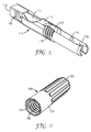
- an optical fiber connector 100 is shown in isometric view in Fig. 1 .
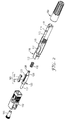
- the components of the optical fiber connector are shown in an exploded view in Fig. 2 .
- Fig. 3 shows a section view of the optical fiber connector 100.
- Figs. 4-6 show close up views of elements of the optical fiber connector, including the collar body 120, the backbone 116, and the boot 180.
- Optical connector 100 is configured to mate with a receptacle of a corresponding format.
- exemplary optical connector 100 is configured as having an SC format.
- optical connectors having other standard formats, such as ST, FC, and LC connector formats can also be provided.
- SC-type optical fiber connector 100 can include a connector body having a housing 110 and a fiber boot 180.
- a cap 190 can be placed at the front end of the connector to protect the stub fiber end when not in use.
- Connector 100 includes a housing 110 having an outer shell configured to be received in an SC receptacle (e.g., an SC coupling, an SC adapter, or an SC socket). As shown in Fig. 2 , connector 100 also includes a collar body 120 (which can also be referred to as a barrel) to house a ferrule and a splice device, a multi-purpose backbone 116 that retains the collar body 120 within the connector, and a boot 180.
- SC receptacle e.g., an SC coupling, an SC adapter, or an SC socket.
- a collar body 120 which can also be referred to as a barrel to house a ferrule and a splice device, a multi-purpose backbone 116 that retains the collar body 120 within the connector, and a boot 180.
- Optical fiber cable 135 is a jacketed cable that includes an outer jacket 136, a coated portion 137 (e.g., with a buffer coating or the like), a fiber portion 138 (e.g., the bare clad/core), and strength members 139.
- the strength members 139 comprise aramid, Kevlar, or polyester yarn or strands disposed between an inner surface of the fiber jacket 136 and an outer surface of coated portion 137.
- Optical fiber cable 135 can be a standard cylindrically shaped cable structure or it can be an alternatively shaped structure, such as a rectangular-shaped cable.
- the backbone 116 provides structural support for the connector 100.
- the backbone 116 is an elongated structure (having a length of from about 50 mm to about 60 mm) that also provides clamping for the optical fiber being terminated in the field.
- the backbone 116 can provide further axial strain relief by providing a clamping surface for the strength members of the optical fiber being terminated.
- Backbone 116 includes an opening 112 at a front end to allow for insertion of the collar body 120 (see e.g., Fig. 7A ).
- Backbone 116 further includes an access opening 117, which can provide access to actuate a mechanical splice device disposed within the connector collar body.
- access opening 117 can have a cut-out or shallow depression formed on the sides to accommodate a user's thumb or finger during actuation of the splice device.
- the backbone 116 has an axial bore throughout to permit passage of the optical fiber being terminated.
- backbone 116 can further include a mounting structure 118 that provides for coupling to the fiber boot 180.
- the mounting structure comprises a threaded surface formed on an outer portion of backbone 116 that is configured to engage a corresponding threaded surface 184 of the boot 180 (see Fig. 6 ). Also, the mounting structure 118 can provide a retention area for securing the strength members of the optical fiber cable being terminated.
- the backbone can include a fiber guide 113 formed in an interior portion therein to provide axial alignment support for the optical fiber cable being terminated.
- the fiber guide portion 113 is a funnel-shaped channel or groove that aligns a buffered portion of the optical fiber and guides the fiber toward the mechanical splice device 140 housed in the collar body 120.
- the backbone 116 also includes a collar body mount structure 115 configured to receive and secure the collar body 120 within the backbone.
- collar body mount structure 115 comprises a rigid structure formed in an interior region of backbone 116 having an axial bore therethrough. The axial bore can be of appropriate size to receive and engage raised end structures 128 of collar body 120 (see Fig. 3 ).
- collar body mount structure 115 also forms a shoulder that can be used as a flange to provide resistance against spring 155 that is positioned over the second end portion 126 of the collar body 120. The spring 155 provides and maintains an adequate contact force when two connectors are joined together.
- Backbone 116 can further include one or more stops 114 formed on an interior portion thereof to provide a boundary for the insertion of the jacketed portion 136 of the optical fiber cable 135 being terminated (as explained in more detail below).
- backbone 116 includes a clamping portion 119 formed at one an end of the backbone.
- the clamping portion 119 is configured to clamp onto the jacket portion 136 of the optical fiber cable 135 being terminated in connector 100.
- clamping portion 119 comprises a collet-type, split body shape that is actuated when the boot is secured to mounting structure 118.
- the clamping portion 119 can include raised inner surfaces to permit ready clamping of the cable jacket portion 136.
- the connector can also include an adapter tube to be placed over the cable jacket portion of the optical fiber cable, for example, when the optical fiber cable being clamped is of a smaller diameter.
- the clamping portion 119 also can provide a guide structure when inserting fiber cable 135 during the termination process.
- boot 180 can be utilized to clamp the fiber strength members 139 and the fiber jacket 136. The interaction of the boot 180 and the backbone 116 will be described in greater detail below.
- housing 110 and backbone 116 are formed or molded from a polymer material, although metal and other suitably rigid materials can also be utilized. Housing 110 is preferably secured to an outer surface of backbone 116 via snap fit (see e.g., outer engagement surface 111 shown in Fig. 5 ).
- connector 100 further includes a collar body 120 that is disposed within the connector housing and retained by the backbone.
- the collar body 120 is a multi-purpose element that can house a ferrule 132 and optical fiber stub 134 and a mechanical splice device 140.
- the collar body is configured to have some limited axial movement within backbone 116.
- the collar body 120 can include a collar or shoulder 125 that can be used as a flange to provide resistance against spring 155 (see Figs. 2 and 3 ), interposed between the collar body and the backbone portion 115.
- collar body 120 can be formed or molded from a polymer material, although metal and other suitable materials can also be utilized.
- collar body 120 can comprise an injection-molded, integral material.
- collar body 120 includes a first end portion 121 having an opening to receive and house a ferrule 132 having an optical fiber stub 134 secured therein.
- the collar body also includes a second end portion 126 configured to engage with the collar body mount structure 115 of backbone 116.
- second end portion 126 has a raised structure portion 128 that has a sloping shape that is insertable through the bore of the collar body mount structure 115, as is shown in Fig. 3 . Raised surfaces 128 of the second end portion can be inserted into the bore and engage against backbone mount structure 115 due to the bias of the spring 155.
- the collar body 120 also secures the fiber stub and ferrule in place in the connector 100.
- Ferrule 132 can be formed from a ceramic, glass, plastic, or metal material to support the optical fiber stub 134 inserted and secured therein. In a preferred aspect, ferrule 132 is a ceramic ferrule.
- An optical fiber stub 134 is inserted through the ferrule 132, such that a first fiber stub end slightly protrudes from or is coincident or coplanar with the end face of ferrule 132.
- this first fiber stub end is factory polished (e.g., a flat or angle-polish, with or without bevels).
- a second end of the fiber stub 134 extends part-way into the interior of the connector 100 and is spliced to the fiber portion 138 of an optical fiber cable (such as optical fiber cable 135).
- the second end of fiber stub 134 can be cleaved (flat or angled, with or without bevels).
- the second end of fiber stub 134 can be polished in the factory to reduce the sharpness of the edge of the fiber, which can create scrapings (debris) as it is installed in the splice element.
- an electrical arc such as one provided by a conventional fusion splicer machine, can be utilized to melt the tip of the fiber and form a rounded end, thereby removing the sharp edges.
- This electrical arc technique can be used in conjunction with polishing by an abrasive material to better control end face shape while reducing possible distortion of the core.
- An alternative non-contact method utilizes laser energy to ablate/melt the tip of the fiber.
- Fibers 134, 138 can comprise standard single mode or multimode optical fiber, such as SMF 28 (available from Corning Inc.).
- fiber stub 134 additionally includes a carbon coating disposed on the outer clad of the fiber to further protect the glass-based fiber.
- fiber stub 134 is pre-installed and secured (e.g., by epoxy or other adhesive) in ferrule 132, which is disposed in the first end portion 121 of collar body 120.
- Ferrule 132 is preferably secured within collar body first end portion 121 via an epoxy or other suitable adhesive.
- pre-installation of the fiber stub can be performed in the factory.
- collar body 120 further includes a splice element housing portion 123.
- splice element housing portion 123 provides an opening 122 in which a mechanical splice element 142 can be inserted and secured in the central cavity of collar body 120.
- mechanical splice element 142 is part of a mechanical splice device (also referred to herein as a splice device or splice), such as a 3MTM FIBRLOKTM mechanical fiber optic splice device, available from 3M Company, of Saint Paul, Minnesota.
- an optical fiber splice device (similar to a 3MTM FIBRLOKTM II mechanical fiber optic splice device) that includes a splice element that comprises a sheet of ductile material having a focus hinge that couples two legs, where each of the legs includes a fiber gripping channel (e.g., a V-type (or similar) groove) to optimize clamping forces for conventional glass optical fibers received therein.
- the ductile material for example, can be aluminum or anodized aluminum.
- a conventional index matching fluid can be preloaded into the V-groove region of the splice element for improved optical connectivity within the splice element. In another aspect, no index matching fluid is utilized.
- the splice element 142 can be configured similar to the splice element from a 3MTM FIBRLOKTM II mechanical fiber optic splice device or a 3MTM FIBRLOKTM 4x4 mechanical fiber optic splice device.
- Other conventional mechanical splice devices can also be utilized in accordance with alternative aspects of the present invention and are described in U.S. Patent Nos. 4,824,197 ; 5,102,212 ; 5,138,681 ; and 5,155,787 , each of which is incorporated by reference herein, in their entirety.
- Mechanical splice element 142 allows a field technician to splice the second end of fiber stub 134 to a stripped fiber portion 138 of an optical fiber cable 135 at a field installation location.
- splice device 140 can include splice element 142 and an actuating cap 144 ( Fig. 2 ). In operation, as the cap 144 is moved from an open position to a closed position (e.g. downward in the embodiment depicted in Fig. 2 or in the direction of arrow 107 in Fig.
- one or more cam bars located on an interior portion of the cap 144 can slide over the splice element legs, urging them toward one another.
- Two fiber ends, e.g., one end of fiber stub 134 and one end of fiber 138 from optical fiber cable 135) are held in place in grooves formed in the splice element and butted against each other and are spliced together in a channel, such as a V-groove channel to provide sufficient optical connection, as the element legs are moved toward one another.
- Splice element 142 is mountable in a mounting device or cradle 124 (partially shown in Fig. 4 ) located in portion 123 of collar body 120.
- cradle 124 is integrally formed in collar body 120, e.g., by molding.
- Cradle 124 can secure (through e.g., snug or snap-fit) the axial and lateral position of the splice element 142.
- the mounting device 124 can be configured to hold the splice element such that the splice device cannot be rotated or easily moved forward or backward once installed.
- the mechanical splice allows a field technician to splice the second end of fiber stub 134 to the fiber of an optical fiber cable 135 at a field installation location.
- the term "splice,” as utilized herein, should not be construed in a limiting sense since splice device 140 can allow removal of a fiber.
- the element can be "re-opened” after initial actuation, where the splice element housing portion can be configured to allow for the removal of the splice cap if so desired by a screw driver or similar device. This configuration permits repositioning of the spliced fibers, followed by replacement of the cap to the actuating position.
- boot 180 can be utilized for several purposes with optical connector 100.
- boot 180 includes a tapered body 182 having an axial bore throughout.
- the boot 180 includes threaded grooves 184 formed on an inner surface of the body 182 at the opening 185, where the grooves are configured to engage with the correspondingly threaded mounting structure 118 of the backbone 116.
- the axial length of boot 180 is configured such that a rear section 183 of the boot, which has a smaller opening than at front opening 185, engages the jacket clamp portion 119 of the backbone.
- the axial movement of the boot relative to the backbone forces the legs of clamp portion 119 to move radially inwards so that the fiber jacket 136 is tightly gripped.
- the strength members 139 of the optical fiber cable can be disposed between the boot and the threaded mounting structure 118 to secure the strength members as the boot is installed. This construction can also provide a connector termination capable of surviving rougher handling and greater pull forces.
- boot 180 is formed from a rigid material.
- one exemplary material can comprise a fiberglass reinforced polyphenylene sulfide compound material.
- the materials used to form the boot 180 and the backbone 116 are the same.
- An exemplary fiber cable utilized in this embodiment comprises a 3.0 mm jacketed drop cable, commercially available from Samsung Cable, Thai-han Cable, and others (all of Korea).
- the optical connector of the exemplary embodiments can be configured to terminate the fibers of other types of jacketed drop cable, including 3.5 mm drop cable, and others.
- the optical fiber connector of the exemplary embodiments is of compact length and is capable of straightforward field termination without the use of a connector termination platform or separate crimping tool.
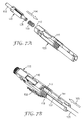
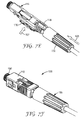
- An exemplary termination process is now described with reference to Figs. 7A - 7F . Please note that reference numbers used in these figures correspond with like features from Figs. 1-6 .
- the optical fiber connector is partly assembled by inserting the collar body 120, with ferrule 132 secured therein, in the direction of arrow 104 into the opening 112 of the backbone 116. This step may be performed prior to the field termination process or during the field termination process. As mentioned above, the raised structure 128 of the collar body is inserted into the bore of structure 115. The spring 155 will provide some bias against axial movement after insertion.
- optical fiber cable 135 is prepared by cutting of a portion of the fiber cable jacket 136 and stripping off a coated portion of the fiber near the terminating fiber end to leave a bare fiber portion 138 and cleaving (flat or angled) the fiber end to match the orientation of the pre-installed fiber stub.
- about 50 mm of the jacket 136 can be removed, leaving about 25 mm of stripped fiber.
- a commercial fiber cleaver such as an Ilsintech MAX CI-01 or the Ilsintech MAX CI-08, available from Israelintech, Korea (not shown) can be utilized to provide a flat or an angled cleave.
- a cleaved fiber can be optically coupled to the fiber stub 134 in the splice device.
- the boot 180 can be slid over the fiber cable 135 for later use.
- optical fiber cable 135 can be inserted in the direction of arrow 105 through the rear end of the connector (i.e., through the clamping portion 119 of the connector backbone).
- the prepared fiber end can be spliced to the fiber stub with the mechanical splice device 140.
- the fiber cable 135 is continually inserted until the coated portion 137 of the fiber begins bowing at 137' (which occurs as the end of fiber 138 meets the fiber stub 134 with sufficient end loading force).
- Fig. 7C shows that the stops 114 formed on an interior portion of the backbone provide a boundary to stop further insertion of the jacketed portion 136 of the optical fiber cable 135.
- the splice device can then be actuated while the fibers are subject to an appropriate end loading force.
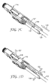
- Fig. 7D shows that a user can simultaneously compress the jacket clamp portion 119 of the backbone by applying force in the direction of arrows 106 (with one hand) while pressing downward (with a modest thumb or finger force) in the direction of arrow 107 onto the cap 144 of the splicing device.
- the fiber jacket can then be released at clamping portion 119, thereby removing the fiber bow.
- the boot 180 (which is previously placed over fiber cable 135) is then pushed onto the backbone 116. As is shown in Fig. 7E , the boot 180 can be pushed axially toward the backbone mounting section 118 and then screwed onto the backbone mounting section 118 to secure the boot 180 in place. As mentioned above, the installation of the boot 180 onto the backbone 116 tightens the collet-style clamping portion 119 onto the fiber jacket. During this installation, the user can hold the Kevlar strands 139 in place over the mounting structure 118 by application of a modest force (e.g., by thumb pressure) in the direction of arrow 108. After completion of the boot installation, the excess Kevlar can be removed (e.g., cut away). As shown in Fig. 7F , the installation can be completed by sliding the housing 110 onto the backbone.
- a modest force e.g., by thumb pressure
- the above termination procedure can be accomplished without the use of any additional fiber termination platform or specialized tool.
- the optical connector is reusable in that the splice cap can be removed and the above steps can be repeated.
- optical connectors described above can be used in many conventional optical connector applications such as drop cables and/or jumpers.
- the optical connectors described above can also be utilized for termination (connectorization) of optical fibers for interconnection and cross connection in optical fiber networks inside a fiber distribution unit at an equipment room or a wall mount patch panel, inside pedestals, cross connect cabinets or closures or inside outlets in premises for optical fiber structured cabling applications.
- the optical connectors described above can also be used in termination of optical fiber in optical equipment.
- one or more of the optical connectors described above can be utilized in alternative applications.
- the optical connector of the exemplary embodiments is of compact length and is capable of straightforward field termination with reduced assembly times.
- Such exemplary connectors can be readily installed and utilized for FTTP and/or FTTX network installations.
Landscapes
- Physics & Mathematics (AREA)
- General Physics & Mathematics (AREA)
- Optics & Photonics (AREA)
- Mechanical Coupling Of Light Guides (AREA)
Claims (9)
- Lichtleitfaser-Steckverbinder (100), Folgendes aufweisend:ein Gehäuse (110), konfiguriert, um zu einem Behältnis zu passen;einen Bundkörper (120), angeordnet im Gehäuse, wobei der Bundkörper einen Faserstumpf (134) einschließt, der in einem ersten Endabschnitt des Bundkörpers angeordnet ist, wobei der Faserstumpf eine erste, in einem Bundring (132) des Faserstumpfs angebrachte Lichtleitfaser einschließt, wobei die erste Lichtleitfaser ein erstes Ende nahe einer Endfläche des Bundrings und ein zweites Ende hat, wobei der Bundkörper weiter eine mechanische Spleißeinrichtung (140) aufweist, die in einem Abschnitt des Bundkörpers angeordnet ist, wobei die mechanische Spleißeinrichtung konfiguriert ist, um das zweite Ende des Faserstumpfs zu einer zweiten Lichtleitfaser (138) zu spleißen;eine Hauptstütze (116) zum Halten des Bundkörpers im Gehäuse, wobei die Hauptstütze einen Fasermantel-Klemmabschnitt (119) aufweist, um einen Mantelabschnitt (136) zu klemmen, der bei Betätigung einen Abschnitt der zweiten Lichtleitfaser umgibt; undeine Hülse (180), anbringbar an einem Abschnitt der Hauptstütze, wobei die Hülse konfiguriert ist, um den Fasermantel-Klemmabschnitt der Hauptstütze beim Anbringen der Hauptstütze zu betätigen.
- Lichtleitfaser-Steckverbinder nach Anspruch 1, wobei die Hülse (180) eine Stärke (139) der zweiten Lichtleitfaser gegen einen Anbringungsabschnitt (118) der Hauptstütze hält.
- Lichtleitfaser-Steckverbinder nach Anspruch 1, wobei der Lichtleitfaser - Steckverbinder konfiguriert ist, um ein SC-Behältnis aufzunehmen.
- Lichtleitfaser-Steckverbinder nach Anspruch 1, wobei die mechanische Spleißeinrichtung ein Spleißelement (142) und eine Betätigungskappe (144) aufweist.
- Lichtleitfaser-Steckverbinder nach Anspruch 1, wobei der Fasermantel-Klemmabschnitt eine zangenartige Form mit geteiltem Körper aufweist.
- Lichtleitfaser-Steckverbinder nach Anspruch 1, wobei die Hülse über einen schraubenartigen Mechanismus an der Hauptstütze angebracht ist.
- Lichtleitfaser-Steckverbinder nach Anspruch 1, wobei die Hauptstütze weiter eine Faserführung (113) aufweist.
- Lichtleitfaser-Steckverbinder nach Anspruch 1, wobei die Hauptstütze weiter eine Zugangsfläche (117) mit einer Öffnung und einer an den Seiten davon ausgebildeten flachen Vertiefung einschließt, um das fingerbetätigte Aktivieren der mechanischen Spleißeinrichtung aufzunehmen.
- Lichtleitfaser-Steckverbinder nach Anspruch 1, wobei die Hauptstütze Anschläge (114) einschließt, die auf einer Innenfläche davon ausgebildet sind, um den Durchgang einer ummantelten Faser (136) durch weiteres Eindringen zu verhindern.
Priority Applications (1)
| Application Number | Priority Date | Filing Date | Title |
|---|---|---|---|
| EP16200020.2A EP3171208A1 (de) | 2008-06-06 | 2009-05-15 | Feldanschliessbarer glasfasersteckverbinder mit spleisselement |
Applications Claiming Priority (2)
| Application Number | Priority Date | Filing Date | Title |
|---|---|---|---|
| US5943308P | 2008-06-06 | 2008-06-06 | |
| PCT/US2009/044073 WO2009148797A1 (en) | 2008-06-06 | 2009-05-15 | Field terminable optical fiber connector with splice element |
Related Child Applications (1)
| Application Number | Title | Priority Date | Filing Date |
|---|---|---|---|
| EP16200020.2A Division EP3171208A1 (de) | 2008-06-06 | 2009-05-15 | Feldanschliessbarer glasfasersteckverbinder mit spleisselement |
Publications (3)
| Publication Number | Publication Date |
|---|---|
| EP2297601A1 EP2297601A1 (de) | 2011-03-23 |
| EP2297601A4 EP2297601A4 (de) | 2016-01-27 |
| EP2297601B1 true EP2297601B1 (de) | 2016-11-23 |
Family
ID=41398432
Family Applications (2)
| Application Number | Title | Priority Date | Filing Date |
|---|---|---|---|
| EP16200020.2A Withdrawn EP3171208A1 (de) | 2008-06-06 | 2009-05-15 | Feldanschliessbarer glasfasersteckverbinder mit spleisselement |
| EP09758958.4A Active EP2297601B1 (de) | 2008-06-06 | 2009-05-15 | In situ anschliessbarer glasfasersteckverbinder mit spleisselement |
Family Applications Before (1)
| Application Number | Title | Priority Date | Filing Date |
|---|---|---|---|
| EP16200020.2A Withdrawn EP3171208A1 (de) | 2008-06-06 | 2009-05-15 | Feldanschliessbarer glasfasersteckverbinder mit spleisselement |
Country Status (5)
| Country | Link |
|---|---|
| US (3) | US8573859B2 (de) |
| EP (2) | EP3171208A1 (de) |
| CN (1) | CN102057308B (de) |
| PL (1) | PL2297601T3 (de) |
| WO (1) | WO2009148797A1 (de) |
Families Citing this family (138)
| Publication number | Priority date | Publication date | Assignee | Title |
|---|---|---|---|---|
| CN102057308B (zh) * | 2008-06-06 | 2013-10-09 | 3M创新有限公司 | 具有接合元件的可现场端接的光纤连接器 |
| US8408815B2 (en) * | 2009-06-18 | 2013-04-02 | Senko Advanced Components, Inc. | Optical fiber connector and adapter |
| EP2460043A1 (de) * | 2009-07-31 | 2012-06-06 | Corning Cable Systems LLC | Glasfaserstecker, kabelanordnungen und herstellungsverfahren dafür |
| US8295669B2 (en) | 2009-08-27 | 2012-10-23 | 3M Innovative Properties Company | Compact optical fiber splice holder device |
| CN102272646B (zh) * | 2009-09-11 | 2014-08-20 | 韩国光导发光元件株式会社 | 现场组装光学连接器 |
| KR100985146B1 (ko) * | 2010-01-06 | 2010-10-05 | 네트워크케이블 주식회사 | Fc타입 현장 조립형 광커넥터 |
| US8388242B2 (en) * | 2010-05-19 | 2013-03-05 | Adc Telecommunications, Inc. | In-line splice with integrated splice holder |
| CN102116910B (zh) * | 2010-05-31 | 2012-07-04 | 王其彪 | 光纤与v型槽粘合一体化冷接技术 |
| US8267596B2 (en) * | 2010-08-23 | 2012-09-18 | Corning Cable Systems Llc | Fiber optic cable assemblies with fiber access apertures and methods of assembly |
| US8998502B2 (en) * | 2010-09-03 | 2015-04-07 | Corning Incorporated | Fiber optic connectors and ferrules and methods for using the same |
| GB2485070B (en) * | 2010-10-28 | 2013-05-08 | Aj World Co Ltd | Field assembled optical connector |
| US20140037250A1 (en) * | 2011-01-04 | 2014-02-06 | 3M Innovative Properties Company | Field installed optical fiber connector for jacketed fiber cable and termination method |
| US9188747B2 (en) | 2011-05-23 | 2015-11-17 | Senko Advanced Components, Inc. | True one piece housing fiber optic adapter |
| US8876407B2 (en) | 2011-05-25 | 2014-11-04 | Tyco Electronics Corporation | Cable anchoring system |
| US8734028B2 (en) | 2011-05-25 | 2014-05-27 | Tyco Electronics Corporation | Tool-less clamping mechanism |
| US8876405B2 (en) | 2011-06-27 | 2014-11-04 | 3M Innovative Properties Company | Field terminable optical connector with splice element for jacketed cable |
| AU2011372009A1 (en) * | 2011-06-30 | 2014-01-16 | Corning Cable Systems (Shanghai) Co., Ltd. | Fiber optic connectors,cable assemblies and method for making the same |
| US8465317B2 (en) * | 2011-10-05 | 2013-06-18 | Senko Advanced Components, Inc. | Latching connector with remote release |
| WO2013059959A1 (en) | 2011-10-25 | 2013-05-02 | Corning Cable Systems (Shanghai) Co., Ltd. | Fiber optic connectors, cable assemblies and method for making the same |
| US20150003790A1 (en) * | 2012-01-12 | 2015-01-01 | 3M Innovative Properties Company | Field mountable duplex optical fiber connector with mechanical splice elements |
| MX2014008294A (es) | 2012-01-13 | 2014-08-21 | 3M Innovative Properties Co | Conector para cubiertas de telecomunicaciones. |
| CN202563124U (zh) * | 2012-02-09 | 2012-11-28 | 泰科电子(上海)有限公司 | 光纤连接器 |
| CN104169766B (zh) | 2012-02-13 | 2016-09-28 | 康宁光电通信有限责任公司 | 光纤电缆子组件和用于制作所述子组件的方法 |
| CN103376513B (zh) * | 2012-04-27 | 2016-08-10 | 3M创新有限公司 | 光纤连接器 |
| WO2013159331A1 (en) * | 2012-04-27 | 2013-10-31 | 3M Innovative Properties Company | Optical fiber connector |
| BR112014029084A2 (pt) | 2012-05-22 | 2017-06-27 | Adc Telecommunications Inc | conector de fibra ótica robusto |
| US8974124B2 (en) | 2012-08-16 | 2015-03-10 | Senko Advanced Components, Inc. | Fiber optic connector |
| JP6433900B2 (ja) | 2012-09-12 | 2018-12-05 | コーニング リサーチ アンド ディヴェロップメント コーポレイション | 遠隔グリップ多心コネクタ |
| US8998506B2 (en) | 2012-09-14 | 2015-04-07 | 3M Innovative Properties Company | Field terminable ST format optical fiber connector |
| US8934751B2 (en) | 2012-11-13 | 2015-01-13 | 3M Innovative Properties Company | Telecommunications cable inlet device |
| CN103969753B (zh) * | 2013-01-25 | 2015-10-14 | 鸿富锦精密工业(深圳)有限公司 | 光纤连接器 |
| EP2972536A4 (de) * | 2013-03-11 | 2016-10-19 | Adc Telecommunications Inc | Glasfaserstecker und glasfaserkabelanordnungen mit einem in der buchse des glasfasersteckers verankerten glasfaserkabel |
| BR112015024236A2 (pt) * | 2013-03-21 | 2017-07-18 | 3M Innovative Properties Co | conector óptico para cabos encapados |
| US9268103B2 (en) | 2013-05-10 | 2016-02-23 | Senko Advanced Components, Inc. | Interlockable fiber optic connector adaptors |
| US9360649B2 (en) | 2013-05-22 | 2016-06-07 | Senko Advanced Components, Inc. | Cable guide for fiber optic cables |
| EP3022599A1 (de) | 2013-07-16 | 2016-05-25 | 3M Innovative Properties Company | Telekommunikationsgehäuse für externe verbindungen |
| WO2015050605A1 (en) | 2013-07-16 | 2015-04-09 | 3M Innovative Properties Company | Strain relief assembly |
| US20160131857A1 (en) | 2013-07-16 | 2016-05-12 | 3M Innovative Properties Company | Connector for telecommunication enclosure |
| JP2015049382A (ja) * | 2013-09-02 | 2015-03-16 | スリーエム イノベイティブ プロパティズ カンパニー | 光ファイバコネクタ |
| CN103472543B (zh) * | 2013-09-27 | 2017-09-05 | 连展科技电子(昆山)有限公司 | 光纤连接器 |
| US9618703B2 (en) | 2013-10-03 | 2017-04-11 | Senko Advanced Components, Inc. | Connector housing for securing an optical cable and methods of use and manufacture thereof |
| US9310568B2 (en) | 2013-11-15 | 2016-04-12 | 3M Innovative Properties Company | Hybrid fiber connector patch cord assemblies |
| US9477049B2 (en) | 2013-12-20 | 2016-10-25 | Senko Advanced Components, Inc. | Lockable connectors and connection assemblies |
| US9535230B2 (en) | 2014-01-31 | 2017-01-03 | Senko Advanced Components, Inc. | Integrated fiber optic cable fan-out connector |
| CN104849814A (zh) * | 2014-02-14 | 2015-08-19 | 鸿富锦精密工业(深圳)有限公司 | 光纤连接器 |
| US9297964B2 (en) | 2014-04-18 | 2016-03-29 | Senko Advanced Components, Inc. | Optical fiber connector assembly |
| US9274287B2 (en) | 2014-05-13 | 2016-03-01 | Senko Advanced Components, Inc. | Optical fiber connector and ferrule |
| US9618702B2 (en) | 2014-06-09 | 2017-04-11 | Senko Advanced Components, Inc. | Reduced-profile data transmission element connectors, adapters, and connection assemblies thereof |
| CN106716204A (zh) * | 2014-07-21 | 2017-05-24 | Te连接荷兰有限责任公司 | 具有锚固至光纤连接器的防护件的光缆的光纤连接器和光缆组件 |
| US9599778B2 (en) | 2014-10-22 | 2017-03-21 | Senko Advanced Components, Inc. | Latching connector with remote release |
| WO2016073273A2 (en) * | 2014-11-04 | 2016-05-12 | 3M Innovative Properties Company | Field installed optical fiber connector for jacketed fiber cable and termination method |
| US9494745B2 (en) | 2015-01-16 | 2016-11-15 | Senko Advanced Components, Inc. | Sealable communication cable connection assemblies |
| US9507101B2 (en) * | 2015-02-03 | 2016-11-29 | SENKO Advanced Components (HK) Ltd. | Optical fiber connector with improved optical fiber cable fixing mechanism |
| BR112017018058B1 (pt) * | 2015-02-25 | 2023-05-02 | Ppc Broadband, Inc | Conector para acoplar um cabo de fibra óptica a um ponto de conexão, e conjunto |
| US9658409B2 (en) | 2015-03-03 | 2017-05-23 | Senko Advanced Components, Inc. | Optical fiber connector with changeable polarity |
| US9684139B2 (en) | 2015-05-29 | 2017-06-20 | Senko Advanced Components, Inc. | Optical fiber connector with changeable gender |
| EP3320382A4 (de) | 2015-07-10 | 2019-02-20 | 3M Innovative Properties Company | Optische faser mit bragg-gitter und dünnschicht-beschichtung sowie verbinder |
| CN204790081U (zh) * | 2015-07-22 | 2015-11-18 | 江苏亨通光网科技有限公司 | 一种通用于fttx室内、外圆形引入光缆的快速连接器 |
| US9817195B2 (en) | 2015-10-13 | 2017-11-14 | 3M Innovative Properties Company | Cable sealing device |
| US9726830B1 (en) | 2016-06-28 | 2017-08-08 | Senko Advanced Components, Inc. | Connector and adapter system for two-fiber mechanical transfer type ferrule |
| CN106066515B (zh) * | 2016-07-27 | 2018-10-26 | 杭州雷特通信技术有限公司 | 一种高效快速生产的光纤活动连接器 |
| US10185102B2 (en) | 2016-11-07 | 2019-01-22 | Corning Research & Development Corporation | Optical fiber connector with integrated installation tools |
| US10228521B2 (en) | 2016-12-05 | 2019-03-12 | Senko Advanced Components, Inc. | Narrow width adapters and connectors with modular latching arm |
| US10078188B1 (en) | 2016-12-05 | 2018-09-18 | Senko Advanced Components, Inc. | Springless push/pull fiber optic connector |
| WO2018125707A1 (en) * | 2016-12-29 | 2018-07-05 | Corning Optical Communications LLC | Fiber optic cable assembly and fabrication method using sequentially arranged boots for multi-fiber ferrule |
| BR102017000982A8 (pt) * | 2017-01-17 | 2023-04-11 | Furukawa Ind S A Produtos Eletricos | Conector para cabo de fibra óptica única e mordente para cabo de fibra óptica única |
| WO2018137172A1 (en) * | 2017-01-25 | 2018-08-02 | Corning Research & Development Corporation | Field terminable optical fiber connector |
| US10185100B2 (en) | 2017-01-30 | 2019-01-22 | Senko Advanced Components, Inc | Modular connector and adapter assembly using a removable anchor device |
| US10725248B2 (en) | 2017-01-30 | 2020-07-28 | Senko Advanced Components, Inc. | Fiber optic receptacle with integrated device therein incorporating a behind-the-wall fiber optic receptacle |
| US10444444B2 (en) | 2017-01-30 | 2019-10-15 | Senko Advanced Components, Inc. | Remote release tab connector assembly |
| US11333836B2 (en) | 2017-01-30 | 2022-05-17 | Senko Advanced Components, Inc. | Adapter for optical connectors |
| CN113156586A (zh) | 2017-01-30 | 2021-07-23 | 扇港元器件股份有限公司 | 具有可逆极性的光学连接器 |
| US10416394B2 (en) | 2017-01-30 | 2019-09-17 | Senko Advanced Components, Inc. | Fiber optic receptacle with integrated device therein |
| US9989712B1 (en) | 2017-03-20 | 2018-06-05 | Senko Advanced Components, Inc | MPO connector assembly with push-pull tab |
| US10754098B2 (en) | 2017-04-07 | 2020-08-25 | Senko Advanced Components, Inc. | Behind the wall optical connector with reduced components |
| US10209461B2 (en) | 2017-04-07 | 2019-02-19 | Senko Advanced Components | Behind the wall optical connector with reduced components |
| US10359583B2 (en) | 2017-04-07 | 2019-07-23 | Senko Advanced Components, Inc. | Behind the wall optical connector with reduced components |
| US10989884B2 (en) | 2017-04-07 | 2021-04-27 | Senko Advanced Components, Inc. | Behind the wall optical connector with reduced components |
| US10718910B2 (en) | 2017-05-03 | 2020-07-21 | Senko Advanced Components, Inc | Field terminated ruggedized fiber optic connector system |
| US10401576B2 (en) | 2017-05-10 | 2019-09-03 | Senko Advanced Components, Inc. | MPO micro-latch-lock connector |
| US10146016B1 (en) | 2017-05-10 | 2018-12-04 | Senko Advanced Components, Inc | MPO micro-latchlock connector |
| US10295759B2 (en) | 2017-05-18 | 2019-05-21 | Senko Advanced Components, Inc. | Optical connector with forward-biasing projections |
| US10359576B2 (en) | 2017-06-15 | 2019-07-23 | Senko Advanced Components, Inc. | SC low profile connector with optional boot |
| EP3646075B1 (de) | 2017-06-28 | 2025-07-30 | Corning Research & Development Corporation | Multiports mit verbindungsanschlüssen mit befestigungsmerkmalen, die flexuren betätigen; und verfahren zur herstellung davon |
| US11668890B2 (en) | 2017-06-28 | 2023-06-06 | Corning Research & Development Corporation | Multiports and other devices having optical connection ports with securing features and methods of making the same |
| US10281668B2 (en) | 2017-07-14 | 2019-05-07 | Senko Advanced Components, Inc. | Ultra-small form factor optical connectors |
| US11822133B2 (en) | 2017-07-14 | 2023-11-21 | Senko Advanced Components, Inc. | Ultra-small form factor optical connector and adapter |
| US10718911B2 (en) | 2017-08-24 | 2020-07-21 | Senko Advanced Components, Inc. | Ultra-small form factor optical connectors using a push-pull boot receptacle release |
| US12001064B2 (en) | 2017-07-14 | 2024-06-04 | Senko Advanced Components, Inc. | Small form factor fiber optic connector with multi-purpose boot |
| US10641972B2 (en) | 2017-08-17 | 2020-05-05 | Senko Advanced Components, Inc | Anti-jam alignment sleeve holder or connector housing for a ferrule assembly |
| JP2019086572A (ja) * | 2017-11-02 | 2019-06-06 | 株式会社フジクラ | 光コネクタ、把持部材、及び、光コネクタの製造方法 |
| US10444442B2 (en) | 2017-11-03 | 2019-10-15 | Senko Advanced Components, Inc. | MPO optical fiber connector |
| US11002923B2 (en) | 2017-11-21 | 2021-05-11 | Senko Advanced Components, Inc. | Fiber optic connector with cable boot release having a two-piece clip assembly |
| US10324262B1 (en) | 2017-12-07 | 2019-06-18 | Wei Min Wang | Field terminable fiber optic connectors |
| WO2019126337A1 (en) * | 2017-12-19 | 2019-06-27 | US Conec, Ltd | Mini duplex connector with push-pull polarity mechanism and carrier |
| US10678000B2 (en) | 2018-01-05 | 2020-06-09 | Senko Advanced Components, Inc. | Pull rod and alignment key for a fiber optic connector and adapter |
| WO2019183070A2 (en) | 2018-03-19 | 2019-09-26 | Senko Advanced Components, Inc. | Removal tool for removing a plural of micro optical connectors from an adapter interface |
| MX2020002280A (es) | 2018-03-28 | 2020-10-07 | Senko Advanced Components Inc | Conector de fibra óptica de diseño compacto con un capuchón de múltiples usos. |
| CA3095881A1 (en) | 2018-04-02 | 2019-10-10 | Senko Advanced Components, Inc | Hybrid ingress protected connector and adapter assembly |
| US11041993B2 (en) | 2018-04-19 | 2021-06-22 | Senko Advanced Components, Inc. | Fiber optic adapter with removable insert for polarity change and removal tool for the same |
| US10948664B2 (en) | 2018-05-08 | 2021-03-16 | Senko Advanced Components, Inc. | Ingress protected optical fiber connector having a reduced diameter with a removable retaining nut |
| US10921528B2 (en) | 2018-06-07 | 2021-02-16 | Senko Advanced Components, Inc. | Dual spring multi-fiber optic connector |
| CN112088327A (zh) | 2018-07-15 | 2020-12-15 | 扇港元器件股份有限公司 | 超小型光学连接器和适配器 |
| US10444441B1 (en) | 2018-08-10 | 2019-10-15 | Senko Advanced Components, Inc. | Pivotable housing for a fiber optic connector |
| CN112534324A (zh) | 2018-08-13 | 2021-03-19 | 扇港元器件股份有限公司 | 用于从插座释放光纤连接器的缆线套管组件 |
| US11086087B2 (en) | 2018-09-12 | 2021-08-10 | Senko Advanced Components, Inc. | LC type connector with clip-on push/pull tab for releasing connector from a receptacle using a cable boot |
| US10921531B2 (en) | 2018-09-12 | 2021-02-16 | Senko Advanced Components, Inc. | LC type connector with push/pull assembly for releasing connector from a receptacle using a cable boot |
| US10921530B2 (en) | 2018-09-12 | 2021-02-16 | Senko Advanced Components, Inc. | LC type connector with push/pull assembly for releasing connector from a receptacle using a cable boot |
| US11092756B2 (en) | 2018-10-10 | 2021-08-17 | Senko Advanced Components, Inc. | Ingress protected connector with an unitary orientation feature |
| US10976502B2 (en) | 2018-10-11 | 2021-04-13 | Seniko Advanced Components, Inc. | Outdoor rated assembly configured to blind mate opposing fiber optic connectors therein with a safety spring assembly |
| US11806831B2 (en) | 2018-11-21 | 2023-11-07 | Senko Advanced Components, Inc. | Fixture and method for polishing fiber optic connector ferrules |
| US11175464B2 (en) | 2018-11-25 | 2021-11-16 | Senko Advanced Components, Inc. | Open ended spring body for use in an optical fiber connector |
| US11689247B2 (en) | 2019-01-16 | 2023-06-27 | Mertek Industries, Llc | Patch cord including wireless components |
| US11307359B2 (en) | 2019-02-07 | 2022-04-19 | Senko Advanced Components, Inc. | Ingress protected, outdoor rated connector with integrated optical connector plug frame |
| US12038613B2 (en) | 2019-03-28 | 2024-07-16 | Senko Advanced Components, Inc. | Behind-the-wall optical connector and assembly of the same |
| US11579379B2 (en) | 2019-03-28 | 2023-02-14 | Senko Advanced Components, Inc. | Fiber optic adapter assembly |
| TWM600397U (zh) * | 2019-04-11 | 2020-08-21 | 連訊通信股份有限公司 | 光纖連接器 |
| CN113495327A (zh) * | 2020-04-07 | 2021-10-12 | 连讯通信(天津)有限公司 | 光纤连接器 |
| US11340406B2 (en) | 2019-04-19 | 2022-05-24 | Senko Advanced Components, Inc. | Small form factor fiber optic connector with resilient latching mechanism for securing within a hook-less receptacle |
| CN112083531B (zh) * | 2019-06-12 | 2021-10-19 | 烽火通信科技股份有限公司 | 一种光纤活动连接器 |
| CN114026480B (zh) | 2019-06-13 | 2023-05-26 | 扇港元器件有限公司 | 用于从插座端口释放光纤连接器的杆驱动闩锁臂和使用方法 |
| US11906795B2 (en) | 2019-06-19 | 2024-02-20 | Senko Advanced Components, Inc. | Fiber optic connector assembly with crimp tube subassembly and method of use |
| US11467354B2 (en) | 2019-07-23 | 2022-10-11 | Senko Advanced Components, Inc. | Ultra-small form factor receptacle for receiving a fiber optic connector opposing a ferrule assembly |
| US11422318B2 (en) | 2019-08-08 | 2022-08-23 | Senko Advanced Components, Inc. | Push pull mechanism for an outdoor rated connector assembly |
| US10845542B1 (en) | 2019-08-19 | 2020-11-24 | Afl Telecommunications Llc | Cable node transition assemblies |
| US11353664B1 (en) | 2019-08-21 | 2022-06-07 | Senko Advanced Components, Inc. | Fiber optic connector |
| US12300943B2 (en) | 2019-09-30 | 2025-05-13 | Mertek Industries, Llc | Patch panel traceable networking system |
| US11520111B2 (en) | 2019-11-13 | 2022-12-06 | Senko Advanced Components, Inc. | Fiber optic connector |
| WO2022005952A1 (en) | 2020-06-29 | 2022-01-06 | Corning Research & Development Corporation | Terminals having a multi-fiber optical connection port that inhibits damage from single-fiber connectors |
| US11604320B2 (en) | 2020-09-30 | 2023-03-14 | Corning Research & Development Corporation | Connector assemblies for telecommunication enclosures |
| EP4237889B1 (de) | 2020-10-30 | 2025-08-27 | Corning Research & Development Corporation | Weibliche faseroptische verbinder mit kipphebel |
| US11880076B2 (en) | 2020-11-30 | 2024-01-23 | Corning Research & Development Corporation | Fiber optic adapter assemblies including a conversion housing and a release housing |
| US11994722B2 (en) | 2020-11-30 | 2024-05-28 | Corning Research & Development Corporation | Fiber optic adapter assemblies including an adapter housing and a locking housing |
| EP4050392A1 (de) * | 2021-02-25 | 2022-08-31 | Corning Research & Development Corporation | Glasfaserzugentlastung |
| US12523821B2 (en) | 2021-04-08 | 2026-01-13 | Commscope Technologies Llc | Telecommunications connector with latch release mechanism |
| EP4354191A4 (de) * | 2021-06-03 | 2024-09-11 | Chaozhou Three-Circle (Group) Co., Ltd. | Ferrulenanordnung und glasfaserschnellverbinder damit |
| CN113359242B (zh) * | 2021-06-22 | 2022-01-28 | 深圳市欧耐特通讯有限公司 | 双回路铠装光纤交叉密集分接结构 |
| US20240427102A1 (en) * | 2023-06-22 | 2024-12-26 | Afl Telecommunications Llc | Optical fiber cassette |
Family Cites Families (41)
| Publication number | Priority date | Publication date | Assignee | Title |
|---|---|---|---|---|
| US4155624A (en) * | 1976-12-23 | 1979-05-22 | Thomas & Betts Corporation | Duplex optical fiber connector |
| US4588256A (en) * | 1982-09-07 | 1986-05-13 | Minnesota Mining And Manufacturing Company | Optical fiber connector |
| JPS60250312A (ja) | 1984-05-26 | 1985-12-11 | Nec Corp | 光フアイバコネクタ |
| JPS6188208A (ja) * | 1984-10-08 | 1986-05-06 | Nec Corp | 光フアイバ・コネクタ |
| US4863235A (en) * | 1986-07-21 | 1989-09-05 | American Telephone And Telegraph Company, At&T Bell Laboratories | Connector for optical fiber cable |
| US4795229A (en) | 1987-05-07 | 1989-01-03 | Amp Incorporated | Strain relief assembly for optical fiber connector |
| FR2615631B1 (fr) * | 1987-05-21 | 1989-08-04 | Radiall Ind | Procede de mise en place d'une fibre optique dans un element de connecteur de fibres optiques, et element de connecteur pour la mise en oeuvre du procede |
| US5102212A (en) * | 1988-04-18 | 1992-04-07 | Minnesota Mining And Manufacturing Company | Stamped precision lightguide interconnect centering element |
| US5159653A (en) * | 1988-04-18 | 1992-10-27 | Minnesota Mining And Manufacturing Company | Optical fiber splice |
| US5138681A (en) | 1988-04-18 | 1992-08-11 | Minnesota Mining And Manufacturing Company | Optical fiber splice |
| US4824197A (en) | 1988-04-18 | 1989-04-25 | Minnesota Mining And Manufacturing Company | Stamped precision lightguide interconnect centering element |
| JPH04212112A (ja) | 1990-07-18 | 1992-08-03 | Fuji Electric Co Ltd | 光ファイバ用コネクタ |
| US5185844A (en) * | 1991-07-29 | 1993-02-09 | At&T Bell Laboratories | Closure for optical fiber connective arrangements and method of providing same |
| US5155787A (en) | 1991-09-06 | 1992-10-13 | Minnesota Mining And Manufacturing Company | Multiple optical fiber splice element having ramped porch |
| US5185148A (en) * | 1991-12-16 | 1993-02-09 | Mycogen Corporation | Process for controlling scarab pests with Bacillus thuringiensis isolates |
| JPH0618746A (ja) | 1992-07-02 | 1994-01-28 | Mitsubishi Cable Ind Ltd | 光ファイバ用コネクタ構造 |
| US5321784A (en) * | 1993-02-18 | 1994-06-14 | Minnesota Mining And Manufacturing Company | Pull-proof, modular fiber optic connector system |
| JP3445479B2 (ja) | 1997-11-26 | 2003-09-08 | 住友電気工業株式会社 | メカニカルスプライス型光コネクタ及びその製造方法 |
| US6019521A (en) * | 1998-02-09 | 2000-02-01 | The Whitaker Corporation | Optical fiber connector |
| KR100320389B1 (ko) | 1998-12-31 | 2005-09-30 | 주식회사 머큐리 | 광케이블 분기장치 |
| US6302596B1 (en) * | 1999-07-07 | 2001-10-16 | International Business Machines Corporation | Small form factor optoelectronic transceivers |
| KR100636442B1 (ko) | 1999-10-08 | 2006-10-18 | 뿌예 소씨에떼 아노님 | 광섬유 케이블 유입구장치 |
| CA2428893C (en) * | 2002-05-31 | 2007-12-18 | Thomas & Betts International, Inc. | Connector for hard-line coaxial cable |
| US7140787B2 (en) * | 2002-08-21 | 2006-11-28 | 3M Innovative Properties Company | Optical fiber mechanical splice with strain relief mechanism |
| US6796722B2 (en) * | 2002-09-19 | 2004-09-28 | Yazaki North America, Inc. | Termination ferrule for fiber optics |
| US7011454B2 (en) * | 2003-08-25 | 2006-03-14 | Panduit Corp. | Reversible fiber optic stub fiber connector |
| US7204644B2 (en) * | 2004-03-24 | 2007-04-17 | Corning Cable Systems Llc | Field installable optical fiber connector |
| US7270487B2 (en) * | 2004-04-30 | 2007-09-18 | Corning Cable Systems Llc | Field installable optical fiber connector |
| JP2006019516A (ja) | 2004-07-01 | 2006-01-19 | Fujitsu Ltd | 波長可変レーザ及びその制御方法 |
| JP4544928B2 (ja) | 2004-07-16 | 2010-09-15 | スリーエム イノベイティブ プロパティズ カンパニー | 光コネクタ及び光ファイバ接続システム |
| JP4416591B2 (ja) | 2004-07-16 | 2010-02-17 | スリーエム イノベイティブ プロパティズ カンパニー | 光コネクタ及び光ファイバ接続システム |
| US7346256B2 (en) * | 2004-11-04 | 2008-03-18 | Panduit Corp. | Re-terminable LC connector assembly and cam termination tool |
| US7359613B2 (en) * | 2005-05-27 | 2008-04-15 | Tyco Electronics Corporation | Optical fiber termination apparatus for taut sheath splicing and method for using the same |
| WO2007050470A1 (en) * | 2005-10-24 | 2007-05-03 | 3M Innovative Properties Company | Optical connector, fiber distribution unit, and fiber termination platform for optical connectors |
| US7393148B2 (en) * | 2005-12-06 | 2008-07-01 | Tyco Electronics Corporation | Optical fiber splicing closures and methods |
| KR100724076B1 (ko) | 2005-12-16 | 2007-06-04 | 네트워크케이블 주식회사 | 현장조립형 광커넥터 |
| US7572064B2 (en) | 2006-07-24 | 2009-08-11 | Corning Cable Systems Llc | Optical fiber mechanical splice connector |
| KR100821298B1 (ko) | 2006-10-18 | 2008-04-11 | 네트워크케이블 주식회사 | 광섬유 고정수단이 개선된 현장조립형 광커넥터 |
| BRPI0807941A2 (pt) * | 2007-02-16 | 2014-07-01 | 3M Innovative Proprietes Company | Conector de fibra ótica de preensão à distância |
| US7785017B2 (en) * | 2007-09-27 | 2010-08-31 | Corning Cable Systems Llc | Strain-relief assemblies and methods for a field-installable fiber optic connector |
| CN102057308B (zh) * | 2008-06-06 | 2013-10-09 | 3M创新有限公司 | 具有接合元件的可现场端接的光纤连接器 |
-
2009
- 2009-05-15 CN CN200980121093.0A patent/CN102057308B/zh not_active Expired - Fee Related
- 2009-05-15 EP EP16200020.2A patent/EP3171208A1/de not_active Withdrawn
- 2009-05-15 WO PCT/US2009/044073 patent/WO2009148797A1/en not_active Ceased
- 2009-05-15 EP EP09758958.4A patent/EP2297601B1/de active Active
- 2009-05-15 US US12/990,520 patent/US8573859B2/en active Active
- 2009-05-15 PL PL09758958T patent/PL2297601T3/pl unknown
-
2013
- 2013-10-29 US US14/066,370 patent/US8840320B2/en active Active
-
2014
- 2014-08-21 US US14/465,433 patent/US9103995B2/en active Active
Also Published As
| Publication number | Publication date |
|---|---|
| EP2297601A1 (de) | 2011-03-23 |
| US20140050445A1 (en) | 2014-02-20 |
| US8840320B2 (en) | 2014-09-23 |
| US20110044588A1 (en) | 2011-02-24 |
| EP2297601A4 (de) | 2016-01-27 |
| CN102057308A (zh) | 2011-05-11 |
| PL2297601T3 (pl) | 2017-05-31 |
| WO2009148797A1 (en) | 2009-12-10 |
| CN102057308B (zh) | 2013-10-09 |
| US20140363130A1 (en) | 2014-12-11 |
| US9103995B2 (en) | 2015-08-11 |
| EP3171208A1 (de) | 2017-05-24 |
| US8573859B2 (en) | 2013-11-05 |
Similar Documents
| Publication | Publication Date | Title |
|---|---|---|
| EP2297601B1 (de) | In situ anschliessbarer glasfasersteckverbinder mit spleisselement | |
| US20190041588A1 (en) | Field installable optical fiber connector for fiber optic cables with rigid strength members | |
| EP2724188B1 (de) | Am einsatzort anschliessbarer optischer verbinder mit spleisselement für ein ummanteltes kabel | |
| US20150003790A1 (en) | Field mountable duplex optical fiber connector with mechanical splice elements | |
| EP1949156B1 (de) | Optischer verbinder und methode der nutzung | |
| US9983366B2 (en) | Field installed optical fiber connector for jacketed fiber cable and termination method | |
| US20140037250A1 (en) | Field installed optical fiber connector for jacketed fiber cable and termination method | |
| US8295669B2 (en) | Compact optical fiber splice holder device | |
| US9383526B2 (en) | Optical fiber connector | |
| KR100944702B1 (ko) | 스플라이스 요소를 갖는 현장 접속가능 광섬유 커넥터 | |
| WO2014040545A1 (en) | Field terminable st format optical fiber connector | |
| WO2018137172A1 (en) | Field terminable optical fiber connector |
Legal Events
| Date | Code | Title | Description |
|---|---|---|---|
| PUAI | Public reference made under article 153(3) epc to a published international application that has entered the european phase |
Free format text: ORIGINAL CODE: 0009012 |
|
| 17P | Request for examination filed |
Effective date: 20101221 |
|
| AK | Designated contracting states |
Kind code of ref document: A1 Designated state(s): AT BE BG CH CY CZ DE DK EE ES FI FR GB GR HR HU IE IS IT LI LT LU LV MC MK MT NL NO PL PT RO SE SI SK TR |
|
| AX | Request for extension of the european patent |
Extension state: AL BA RS |
|
| DAX | Request for extension of the european patent (deleted) | ||
| RA4 | Supplementary search report drawn up and despatched (corrected) |
Effective date: 20160105 |
|
| RIC1 | Information provided on ipc code assigned before grant |
Ipc: G02B 6/38 20060101ALI20151221BHEP Ipc: G02B 6/36 20060101AFI20151221BHEP |
|
| GRAP | Despatch of communication of intention to grant a patent |
Free format text: ORIGINAL CODE: EPIDOSNIGR1 |
|
| INTG | Intention to grant announced |
Effective date: 20160603 |
|
| RIN1 | Information on inventor provided before grant (corrected) |
Inventor name: PARK, CHANSOOL Inventor name: LARSON, DONALD K. |
|
| GRAS | Grant fee paid |
Free format text: ORIGINAL CODE: EPIDOSNIGR3 |
|
| GRAA | (expected) grant |
Free format text: ORIGINAL CODE: 0009210 |
|
| AK | Designated contracting states |
Kind code of ref document: B1 Designated state(s): AT BE BG CH CY CZ DE DK EE ES FI FR GB GR HR HU IE IS IT LI LT LU LV MC MK MT NL NO PL PT RO SE SI SK TR |
|
| REG | Reference to a national code |
Ref country code: GB Ref legal event code: FG4D |
|
| REG | Reference to a national code |
Ref country code: CH Ref legal event code: EP |
|
| REG | Reference to a national code |
Ref country code: IE Ref legal event code: FG4D |
|
| REG | Reference to a national code |
Ref country code: AT Ref legal event code: REF Ref document number: 848425 Country of ref document: AT Kind code of ref document: T Effective date: 20161215 |
|
| REG | Reference to a national code |
Ref country code: DE Ref legal event code: R096 Ref document number: 602009042630 Country of ref document: DE |
|
| PG25 | Lapsed in a contracting state [announced via postgrant information from national office to epo] |
Ref country code: LV Free format text: LAPSE BECAUSE OF FAILURE TO SUBMIT A TRANSLATION OF THE DESCRIPTION OR TO PAY THE FEE WITHIN THE PRESCRIBED TIME-LIMIT Effective date: 20161123 |
|
| REG | Reference to a national code |
Ref country code: LT Ref legal event code: MG4D |
|
| REG | Reference to a national code |
Ref country code: NL Ref legal event code: MP Effective date: 20161123 |
|
| REG | Reference to a national code |
Ref country code: FR Ref legal event code: PLFP Year of fee payment: 9 |
|
| REG | Reference to a national code |
Ref country code: AT Ref legal event code: MK05 Ref document number: 848425 Country of ref document: AT Kind code of ref document: T Effective date: 20161123 |
|
| PG25 | Lapsed in a contracting state [announced via postgrant information from national office to epo] |
Ref country code: NL Free format text: LAPSE BECAUSE OF FAILURE TO SUBMIT A TRANSLATION OF THE DESCRIPTION OR TO PAY THE FEE WITHIN THE PRESCRIBED TIME-LIMIT Effective date: 20161123 Ref country code: LT Free format text: LAPSE BECAUSE OF FAILURE TO SUBMIT A TRANSLATION OF THE DESCRIPTION OR TO PAY THE FEE WITHIN THE PRESCRIBED TIME-LIMIT Effective date: 20161123 Ref country code: GR Free format text: LAPSE BECAUSE OF FAILURE TO SUBMIT A TRANSLATION OF THE DESCRIPTION OR TO PAY THE FEE WITHIN THE PRESCRIBED TIME-LIMIT Effective date: 20170224 Ref country code: SE Free format text: LAPSE BECAUSE OF FAILURE TO SUBMIT A TRANSLATION OF THE DESCRIPTION OR TO PAY THE FEE WITHIN THE PRESCRIBED TIME-LIMIT Effective date: 20161123 Ref country code: NO Free format text: LAPSE BECAUSE OF FAILURE TO SUBMIT A TRANSLATION OF THE DESCRIPTION OR TO PAY THE FEE WITHIN THE PRESCRIBED TIME-LIMIT Effective date: 20170223 |
|
| REG | Reference to a national code |
Ref country code: ES Ref legal event code: FG2A Ref document number: 2613486 Country of ref document: ES Kind code of ref document: T3 Effective date: 20170524 |
|
| PG25 | Lapsed in a contracting state [announced via postgrant information from national office to epo] |
Ref country code: AT Free format text: LAPSE BECAUSE OF FAILURE TO SUBMIT A TRANSLATION OF THE DESCRIPTION OR TO PAY THE FEE WITHIN THE PRESCRIBED TIME-LIMIT Effective date: 20161123 Ref country code: PT Free format text: LAPSE BECAUSE OF FAILURE TO SUBMIT A TRANSLATION OF THE DESCRIPTION OR TO PAY THE FEE WITHIN THE PRESCRIBED TIME-LIMIT Effective date: 20170323 Ref country code: HR Free format text: LAPSE BECAUSE OF FAILURE TO SUBMIT A TRANSLATION OF THE DESCRIPTION OR TO PAY THE FEE WITHIN THE PRESCRIBED TIME-LIMIT Effective date: 20161123 Ref country code: FI Free format text: LAPSE BECAUSE OF FAILURE TO SUBMIT A TRANSLATION OF THE DESCRIPTION OR TO PAY THE FEE WITHIN THE PRESCRIBED TIME-LIMIT Effective date: 20161123 |
|
| PG25 | Lapsed in a contracting state [announced via postgrant information from national office to epo] |
Ref country code: EE Free format text: LAPSE BECAUSE OF FAILURE TO SUBMIT A TRANSLATION OF THE DESCRIPTION OR TO PAY THE FEE WITHIN THE PRESCRIBED TIME-LIMIT Effective date: 20161123 Ref country code: RO Free format text: LAPSE BECAUSE OF FAILURE TO SUBMIT A TRANSLATION OF THE DESCRIPTION OR TO PAY THE FEE WITHIN THE PRESCRIBED TIME-LIMIT Effective date: 20161123 Ref country code: SK Free format text: LAPSE BECAUSE OF FAILURE TO SUBMIT A TRANSLATION OF THE DESCRIPTION OR TO PAY THE FEE WITHIN THE PRESCRIBED TIME-LIMIT Effective date: 20161123 Ref country code: CZ Free format text: LAPSE BECAUSE OF FAILURE TO SUBMIT A TRANSLATION OF THE DESCRIPTION OR TO PAY THE FEE WITHIN THE PRESCRIBED TIME-LIMIT Effective date: 20161123 Ref country code: DK Free format text: LAPSE BECAUSE OF FAILURE TO SUBMIT A TRANSLATION OF THE DESCRIPTION OR TO PAY THE FEE WITHIN THE PRESCRIBED TIME-LIMIT Effective date: 20161123 |
|
| REG | Reference to a national code |
Ref country code: DE Ref legal event code: R097 Ref document number: 602009042630 Country of ref document: DE |
|
| PG25 | Lapsed in a contracting state [announced via postgrant information from national office to epo] |
Ref country code: BE Free format text: LAPSE BECAUSE OF FAILURE TO SUBMIT A TRANSLATION OF THE DESCRIPTION OR TO PAY THE FEE WITHIN THE PRESCRIBED TIME-LIMIT Effective date: 20161123 Ref country code: LU Free format text: LAPSE BECAUSE OF NON-PAYMENT OF DUE FEES Effective date: 20170531 Ref country code: BG Free format text: LAPSE BECAUSE OF FAILURE TO SUBMIT A TRANSLATION OF THE DESCRIPTION OR TO PAY THE FEE WITHIN THE PRESCRIBED TIME-LIMIT Effective date: 20170223 |
|
| PLBE | No opposition filed within time limit |
Free format text: ORIGINAL CODE: 0009261 |
|
| STAA | Information on the status of an ep patent application or granted ep patent |
Free format text: STATUS: NO OPPOSITION FILED WITHIN TIME LIMIT |
|
| 26N | No opposition filed |
Effective date: 20170824 |
|
| PG25 | Lapsed in a contracting state [announced via postgrant information from national office to epo] |
Ref country code: SI Free format text: LAPSE BECAUSE OF FAILURE TO SUBMIT A TRANSLATION OF THE DESCRIPTION OR TO PAY THE FEE WITHIN THE PRESCRIBED TIME-LIMIT Effective date: 20161123 |
|
| REG | Reference to a national code |
Ref country code: CH Ref legal event code: PL |
|
| PG25 | Lapsed in a contracting state [announced via postgrant information from national office to epo] |
Ref country code: MC Free format text: LAPSE BECAUSE OF FAILURE TO SUBMIT A TRANSLATION OF THE DESCRIPTION OR TO PAY THE FEE WITHIN THE PRESCRIBED TIME-LIMIT Effective date: 20161123 |
|
| REG | Reference to a national code |
Ref country code: IE Ref legal event code: MM4A |
|
| PG25 | Lapsed in a contracting state [announced via postgrant information from national office to epo] |
Ref country code: CH Free format text: LAPSE BECAUSE OF NON-PAYMENT OF DUE FEES Effective date: 20170531 Ref country code: LI Free format text: LAPSE BECAUSE OF NON-PAYMENT OF DUE FEES Effective date: 20170531 |
|
| PG25 | Lapsed in a contracting state [announced via postgrant information from national office to epo] |
Ref country code: LU Free format text: LAPSE BECAUSE OF NON-PAYMENT OF DUE FEES Effective date: 20170515 |
|
| REG | Reference to a national code |
Ref country code: FR Ref legal event code: PLFP Year of fee payment: 10 |
|
| PG25 | Lapsed in a contracting state [announced via postgrant information from national office to epo] |
Ref country code: IE Free format text: LAPSE BECAUSE OF NON-PAYMENT OF DUE FEES Effective date: 20170515 |
|
| REG | Reference to a national code |
Ref country code: DE Ref legal event code: R081 Ref document number: 602009042630 Country of ref document: DE Owner name: CORNING RESEARCH DEVELOPMENT CORP., CORNING, US Free format text: FORMER OWNER: 3M INNOVATIVE PROPERTIES COMPANY, ST. PAUL, MINN., US Ref country code: DE Ref legal event code: R081 Ref document number: 602009042630 Country of ref document: DE Owner name: CORNING RESEARCH & DEVELOPMENT CORP., CORNING, US Free format text: FORMER OWNER: 3M INNOVATIVE PROPERTIES COMPANY, ST. PAUL, MN, US Ref country code: DE Ref legal event code: R081 Ref document number: 602009042630 Country of ref document: DE Owner name: CORNING RESEARCH & DEVELOPMENT CORP., CORNING, US Free format text: FORMER OWNER: 3M INNOVATIVE PROPERTIES COMPANY, ST. PAUL, MINN., US |
|
| REG | Reference to a national code |
Ref country code: GB Ref legal event code: 732E Free format text: REGISTERED BETWEEN 20180726 AND 20180801 |
|
| PG25 | Lapsed in a contracting state [announced via postgrant information from national office to epo] |
Ref country code: MT Free format text: LAPSE BECAUSE OF NON-PAYMENT OF DUE FEES Effective date: 20170515 |
|
| REG | Reference to a national code |
Ref country code: ES Ref legal event code: PC2A Owner name: CORNING RESEARCH & DEVELOPMENT CORPORATION Effective date: 20181015 |
|
| PG25 | Lapsed in a contracting state [announced via postgrant information from national office to epo] |
Ref country code: HU Free format text: LAPSE BECAUSE OF FAILURE TO SUBMIT A TRANSLATION OF THE DESCRIPTION OR TO PAY THE FEE WITHIN THE PRESCRIBED TIME-LIMIT; INVALID AB INITIO Effective date: 20090515 |
|
| PGFP | Annual fee paid to national office [announced via postgrant information from national office to epo] |
Ref country code: SE Payment date: 20190627 Year of fee payment: 12 |
|
| PG25 | Lapsed in a contracting state [announced via postgrant information from national office to epo] |
Ref country code: CY Free format text: LAPSE BECAUSE OF NON-PAYMENT OF DUE FEES Effective date: 20161123 |
|
| PG25 | Lapsed in a contracting state [announced via postgrant information from national office to epo] |
Ref country code: MK Free format text: LAPSE BECAUSE OF FAILURE TO SUBMIT A TRANSLATION OF THE DESCRIPTION OR TO PAY THE FEE WITHIN THE PRESCRIBED TIME-LIMIT Effective date: 20161123 |
|
| PG25 | Lapsed in a contracting state [announced via postgrant information from national office to epo] |
Ref country code: TR Free format text: LAPSE BECAUSE OF FAILURE TO SUBMIT A TRANSLATION OF THE DESCRIPTION OR TO PAY THE FEE WITHIN THE PRESCRIBED TIME-LIMIT Effective date: 20161123 |
|
| PG25 | Lapsed in a contracting state [announced via postgrant information from national office to epo] |
Ref country code: IS Free format text: LAPSE BECAUSE OF FAILURE TO SUBMIT A TRANSLATION OF THE DESCRIPTION OR TO PAY THE FEE WITHIN THE PRESCRIBED TIME-LIMIT Effective date: 20170323 |
|
| PG25 | Lapsed in a contracting state [announced via postgrant information from national office to epo] |
Ref country code: PL Free format text: LAPSE BECAUSE OF NON-PAYMENT OF DUE FEES Effective date: 20200515 |
|
| REG | Reference to a national code |
Ref country code: FR Ref legal event code: PLFP Year of fee payment: 15 |
|
| P01 | Opt-out of the competence of the unified patent court (upc) registered |
Effective date: 20230527 |
|
| PGFP | Annual fee paid to national office [announced via postgrant information from national office to epo] |
Ref country code: IT Payment date: 20230510 Year of fee payment: 15 Ref country code: ES Payment date: 20230607 Year of fee payment: 15 Ref country code: DE Payment date: 20230412 Year of fee payment: 15 |
|
| REG | Reference to a national code |
Ref country code: DE Ref legal event code: R119 Ref document number: 602009042630 Country of ref document: DE |
|
| PG25 | Lapsed in a contracting state [announced via postgrant information from national office to epo] |
Ref country code: DE Free format text: LAPSE BECAUSE OF NON-PAYMENT OF DUE FEES Effective date: 20241203 |
|
| PG25 | Lapsed in a contracting state [announced via postgrant information from national office to epo] |
Ref country code: IT Free format text: LAPSE BECAUSE OF NON-PAYMENT OF DUE FEES Effective date: 20240515 |
|
| REG | Reference to a national code |
Ref country code: ES Ref legal event code: FD2A Effective date: 20250627 |
|
| PG25 | Lapsed in a contracting state [announced via postgrant information from national office to epo] |
Ref country code: ES Free format text: LAPSE BECAUSE OF NON-PAYMENT OF DUE FEES Effective date: 20240516 |
|
| PGFP | Annual fee paid to national office [announced via postgrant information from national office to epo] |
Ref country code: GB Payment date: 20250410 Year of fee payment: 17 |
|
| PGFP | Annual fee paid to national office [announced via postgrant information from national office to epo] |
Ref country code: FR Payment date: 20250409 Year of fee payment: 17 |