EP2296238A1 - Box for electrical switchgear - Google Patents
Box for electrical switchgear Download PDFInfo
- Publication number
- EP2296238A1 EP2296238A1 EP10290458A EP10290458A EP2296238A1 EP 2296238 A1 EP2296238 A1 EP 2296238A1 EP 10290458 A EP10290458 A EP 10290458A EP 10290458 A EP10290458 A EP 10290458A EP 2296238 A1 EP2296238 A1 EP 2296238A1
- Authority
- EP
- European Patent Office
- Prior art keywords
- box
- lines
- side wall
- boxes
- side walls
- Prior art date
- Legal status (The legal status is an assumption and is not a legal conclusion. Google has not performed a legal analysis and makes no representation as to the accuracy of the status listed.)
- Granted
Links
- 238000005336 cracking Methods 0.000 abstract 1
- 238000010616 electrical installation Methods 0.000 abstract 1
- 229920003023 plastic Polymers 0.000 description 2
- 238000007789 sealing Methods 0.000 description 2
- 210000002105 tongue Anatomy 0.000 description 2
- 230000000903 blocking effect Effects 0.000 description 1
- 239000000428 dust Substances 0.000 description 1
- 238000010292 electrical insulation Methods 0.000 description 1
- 229920002457 flexible plastic Polymers 0.000 description 1
- 238000009434 installation Methods 0.000 description 1
- 239000011810 insulating material Substances 0.000 description 1
- 238000009413 insulation Methods 0.000 description 1
- 238000000465 moulding Methods 0.000 description 1
- 239000002245 particle Substances 0.000 description 1
- 230000000630 rising effect Effects 0.000 description 1
Images


Classifications
-
- H—ELECTRICITY
- H02—GENERATION; CONVERSION OR DISTRIBUTION OF ELECTRIC POWER
- H02B—BOARDS, SUBSTATIONS OR SWITCHING ARRANGEMENTS FOR THE SUPPLY OR DISTRIBUTION OF ELECTRIC POWER
- H02B1/00—Frameworks, boards, panels, desks, casings; Details of substations or switching arrangements
- H02B1/26—Casings; Parts thereof or accessories therefor
- H02B1/46—Boxes; Parts thereof or accessories therefor
-
- H—ELECTRICITY
- H02—GENERATION; CONVERSION OR DISTRIBUTION OF ELECTRIC POWER
- H02B—BOARDS, SUBSTATIONS OR SWITCHING ARRANGEMENTS FOR THE SUPPLY OR DISTRIBUTION OF ELECTRIC POWER
- H02B1/00—Frameworks, boards, panels, desks, casings; Details of substations or switching arrangements
- H02B1/26—Casings; Parts thereof or accessories therefor
- H02B1/30—Cabinet-type casings; Parts thereof or accessories therefor
- H02B1/308—Mounting of cabinets together
Definitions
- the present invention generally relates to a box for electrical equipment having a bottom and four side walls rising perpendicularly to this bottom, at least one side wall having a plurality of lines of lower strength allowing a break in the side wall of the along two of these first lines and the removal of a removable portion of said side wall located between these two lines.
- An object of the present invention is to allow the combination of boxes of different sizes or the combination of several boxes of reduced dimensions along the same side wall of another box of larger dimensions.
- the corresponding side wall can be broken in two different ways, or along two lines of lower successive strength, so as to open a window of reduced dimensions at one or the other of two different locations on the side wall or along the two lines of the lowest resistance furthest away, so as to open a larger window in the side wall.
- Such a window can thus be opened to the right of each row of electrical equipment, so as to facilitate the association of two boxes together.
- Each of these boxes 10, 20, 30 has a bottom 11, 21, 31 having a rectangular or square shape and four side walls 12, 13, 14, 15, 22, 23, 24, 25, 32, 33, 34, 35 which rise from this bottom 11, 21, 31, perpendicular to it, along each of its sides. They are made of insulating material, for example plastic.
- each of the boxes 10, 20, 30 according to the invention comprises at least one side wall 13, 14, 15, 22, 23, 24, 25, 33, 35 comprising at least three lines 17, 27, 37 of lower resistance allowing a break of this side wall 13, 14, 15, 22, 23, 24, 25, 33, 35 along a any couple of these lines 17 of lower strength.
- the lines 17 of lower resistance are represented for example on the figure 2 which shows the side wall 14 of a first of the three boxes 10, 20, 30, called main box 10, before breaking of this wall along these lines 17.
- This wall 14 of the main box 10 has five lines 17 more low resistance.
- the sidewalls 22, 23, 24, 25 of the second box 20 and the sidewalls 33, 35 of the third box 30 shown in FIG. figure 1 each has three lines 27, 37 of lower resistance.
- the relevant sidewalls 13, 14, 15, 22, 23, 24, 25, 33, 35 may be broken along two successive lines 17, 27, 37 so as to allow the withdrawal, at several different locations of the concerned wall, a removable portion 16, 26, 36 of this wall, whose length is equal to the interval between the two successive lines 17.
- This withdrawal makes it possible to open, for example, a window 14B in the side wall 14.
- the sidewalls 13, 14, 15, 22, 23, 24, 25, 33, 35 concerned may also be broken along two lines 17, 27, 37 further away so as to allow the removal of a larger portion of this wall.
- This withdrawal makes it possible to open, for example, a window 14A, 24A, 25A, 35A of larger dimensions than the window 14B in the side wall 14, 24, 25, 35.
- Each of these lines 17, 27, 37 of lower resistance extends perpendicular to the bottom 11, 21, 31 of the box 10, 20, 30, from this bottom to the free edge of the corresponding side wall.
- Each line 17, 27, 37 of lower resistance corresponds for example to a zone of the side wall 13, 14, 15, 22, 23, 24, 25, 33, 35 having a thickness less than the thickness of the rest of this wall.
- the mechanical strength of the wall is lower along this line, and the wall breaks easily along this line.
- This zone of thickness less than the thickness of the remainder of the side wall is for example made by local thinning of this wall during its molding.
- the bottom 11, 21, 31 of each box 10, 20, 30 also comprises lines of lower resistance which run along the side walls 13, 14, 15, 22, 23, 24, 25, 33, 35 between the lines 17, 27, 37 of lower resistance of these side walls.
- the box 10, 20 according to the invention is adapted to accommodate a number of rows of modular electrical equipment greater than two.
- the rows of modular equipment are then mounted on as many support rails which extend perpendicularly to two opposite side walls 12, 14, 22, 24 of this box 10, 20, hereinafter referred to as the longitudinal side walls 12, 14, 22, 24.
- the box 10, 20 then comprises, on at least one of these two longitudinal side walls 12, 14, 22, 24, a number of lines 17, 27 of lower resistance equal to the number of rows of electrical equipment. plus one.
- the main box 10 is here adapted to accommodate four rows of modular devices (not shown) and has an elongated rectangular shape of longitudinal axis X.
- the longitudinal side wall 14 of the main box 10 has five lines 17 of lower strength.
- the five lines 17 of lower resistance of the longitudinal side wall 14 delimit four removable portions 16 of this wall.
- the five lines 17 of lower resistance of the longitudinal side wall 14 are spaced here by a regular pitch equal to 150 millimeters, and placed so that each of the four removable portions 16 of this wall is located opposite the the end of one of the four rows of electrical equipment housed in the main box 10.
- the number and the positioning of the lines 17 of lower resistance thus facilitate the electrical connection of the electrical equipment mounted on the support rails of the two associated boxes.
- two windows 14A, 14B are open in the longitudinal side wall 14 by the removal of three removable portions 16: the first window 14A is obtained by the removal of two removable portions 16 and thus measures twice the spacing pitch of the lines 17 of lower resistance, here 300 mm, while the second window 14B is obtained by the removal of a removable portion 16 and thus once the spacing step 17 of lower resistance, here 150 mm.
- the box according to the invention it is also possible thanks to the box according to the invention to open in the longitudinal side wall 14 of the main box 10 a single window width equal to once, twice, three times or four times the step of spacing lines 17 of lower strength, here 150, 300, 450 or 600 millimeters, and place the window size less than 600 millimeters at different locations on the longitudinal side wall 14.
- the secondary box 20 is adapted to house two rows of electrical equipment. It comprises here in each of its side walls 22, 23, 24, 25 three lines 27 of lower strength. These three lines 27 are visible on the side wall 22 of the secondary box 20 of the figure 1 . As shown in figure 1 , the removal of the two removable portions of the side wall 24 of the secondary box 20 adjacent to the main box 10 creates an opening 24A of the same dimensions as the opening 14A of the longitudinal side wall 14 of the main box 10.
- Tertiary box 30 is adapted to house a single row of electrical equipment. It comprises here in two of its side walls 33, three lines 37 of lower resistance and in the other two side walls 32, 34 two lines 37 of lower strength. As shown in figure 1 , the removal of a removable portion 36 of the side wall 34 adjacent to the main box 10 opens a window 34A of the same dimensions as the window 14B of the longitudinal side wall 14 of the main box 10, which allows to associate the main and tertiary boxes 30.
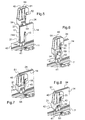
- At least one jumper 40 and at least one tab 42 is provided. represented in particular on the Figures 4 to 9 , which respectively cooperate with the cut edges of the side walls 14, 24, 34, 25, 35 of each pair of boxes and with the cut edges of the bottoms 11, 21, 31 of these pairs of boxes.
- jumpers 40 and tabs 42 used depends on the number of windows open in the side walls of the boxes and the length of these windows.
- jumpers 40 for each pair of windows put in vis-à-vis for the association of two boxes and a number of tabs sufficient to cover the entire length of each of its pairs of windows.
- the tabs 42 are made for example of flexible plastic. They comprise in each of their longitudinal slices a groove adapted to cooperate with the cut edge of the bottom 11, 21, 31 of said box 10, 20, 30.
- Each tab 42 has a length equal to the spacing pitch of the lines 17, 27, 37 of lower resistance.
- Each jumper 40 is preferably made of rigid plastic. It has a U-shaped profile adapted to grip the cut edge of the side walls 14, 24, 34, 25, 35 of two boxes 10, 20, 30 placed side by side to hold them together in a dust-tight manner and electrically isolated.
- each jumper 40 The spacing of the two lateral wings 51 of each jumper 40 is substantially equal to twice the thickness of the side wall 14, 24, 34, 25, 35 of the boxes 10, 20, 30, with a clearance close allowing the assembly of this jumper 40.
- the side walls 14, 24, 34, 25, 35 whose cut edges are inserted in said rider 40 are thus clamped against each other, as shown in FIG. figure 8 ..
- each jumper 40 is substantially equal to the height of the side walls 14, 24, 34, 25, 35 of each box 10, 20, 30, so that it covers most of the cut edge of each side wall 14 , 24, 34, 25, 35 ( figure 8 ).
- Each box 10, 20, 30 also comprises positioning means 43 of said jumper 40 with respect to each side wall 14, 24, 34, 25, 35 on which it is mounted.
- These positioning means comprise, on the inner face of each side wall 14, 24, 34, 25, 35, disposed on either side of each line 17, 27, 37 of lower strength of each box, two amounts 43 which form with said side wall 14, 24, 34, 25, 35 two grooves open towards each other, as shown in FIG. figure 3 .
- Each post 43 protrudes from the inner face of each side wall 14, 24, 34, 25, 35, towards the inside of the corresponding box. It extends parallel to the line 17, 27, 37 of lower resistance corresponding and here comprises a return in the direction of this line 17, 27, 37 of lower resistance.
- These positioning means also comprise, in each lateral wing 51 of the rider 40, a notch 52 adapted to house the free end of one of said uprights 43 ( Figures 5 and 6 ).
- the user places the windows 14A, 14B, 24A, 34A, 25A, 35A open in the side walls 14, 24, 25, 35 of two boxes facing each other, so that the cut edges of each wall 14, 24, 34, 25, 35 and each bottom 11, 21, 31 are arranged in parallel.
- the user installs the tabs 42 by inserting the cut edge of the bottoms 11, 21, 31 of each box 10, 20, 30 to be associated in the grooves of the longitudinal slices of the tabs 42.
- each tab 42 having a length equal to the spacing pitch between two lines 17, 27, 37 of lower resistance of each side wall, the user therefore installs between the two boxes to associate a number of tabs 42 equal to the number removable portions 16, 26, 36 removed to open the corresponding window.
- tongues 42 thus provide a tight and insulating connection between the two bottoms of the two associated boxes.
- each wing 51 of the rider 40 is guided by the grooves formed by the uprights 43 whose access has been released by the removal of the corresponding removable portions 16, 26, 36 of each side wall 14, 24, 34, 25, 35.
- each upright 43 engages in a notch 52 of the corresponding wing 51 of the rider 40.
- each wing 51 of the rider 40 then overlaps the free end of the corresponding post 43, blocking any movement of the rider in the plane of the corresponding side wall.
- Each jumper 40 also has fastening elements 53 ( Figures 5 to 8 ) which protrude from each of the wings 51 of the rider 40 and are adapted to be screwed onto the screwing well 41 closest to the upright 43 which cooperate with the rider 40.
- each fixing element 53 of the Jumper 40 covers the corresponding screwing well 41 and further comprises a through opening disposed opposite the opening of this screwing well 41 allowing the passage of a fixing screw 44.
- the jumper 40 is then fixed on each side to each of the two boxes 10, 20, 30 to associate and holds firmly the two side walls 14, 24, 25, 34, 35 adjacent two contiguous boxes.
- a jumper 40 is installed at each end of the pairs 14A, 24A, 14B, 34A, 25A, 35A of windows put vis-à-vis.
- the base of the jumper 40 intended to come into contact with the bottom 11, 21, 31 of the box 10, 20, 30 includes a hook 54 which accommodates the end of the tongue 42 connecting the funds 11, 21, 31 corresponding to the two boxes to associate so that the base of the rider 40 fits perfectly to the bottom of the associated boxes.
Abstract
Description
La présente invention concerne de manière générale une boîte pour appareillages électriques comportant un fond et quatre parois latérales s'élevant perpendiculairement à ce fond, dont au moins une paroi latérale comportant une pluralité de lignes de plus faible résistance autorisant une cassure de la paroi latérale le long de deux de ces premières lignes et le retrait d'une portion amovible de ladite paroi latérale située entre ces deux lignes.The present invention generally relates to a box for electrical equipment having a bottom and four side walls rising perpendicularly to this bottom, at least one side wall having a plurality of lines of lower strength allowing a break in the side wall of the along two of these first lines and the removal of a removable portion of said side wall located between these two lines.
On connaît déjà, notamment du document
L'inconvénient principal d'une telle boîte est qu'elle ne peut pas être associée à une boîte du même type mais de longueur et donc de capacité différente.The main disadvantage of such a box is that it can not be associated with a box of the same type but of length and therefore of different capacity.
On connaît également du document
Un but de la présente invention est de permettre l'association de boîtes de tailles différentes ou l'association de plusieurs boîtes de dimensions réduites le long d'une même paroi latérale d'une autre boîte de plus grandes dimensions.An object of the present invention is to allow the combination of boxes of different sizes or the combination of several boxes of reduced dimensions along the same side wall of another box of larger dimensions.
A cet effet, on propose selon l'invention une boîte pour appareillages électriques telle que décrite dans la revendication 1.For this purpose, a box for electrical equipment as described in claim 1 is proposed according to the invention.
Ainsi la paroi latérale correspondante peut être cassée de deux manières différentes, soit le long de deux lignes de plus faible résistance successives, de manière à ouvrir une fenêtre de dimensions réduites à l'un ou l'autre de deux endroits différents sur la paroi latérale, soit le long des deux lignes de plus faible résistance les plus éloignées, de manière à ouvrir une fenêtre de plus grandes dimensions dans la paroi latérale.Thus the corresponding side wall can be broken in two different ways, or along two lines of lower successive strength, so as to open a window of reduced dimensions at one or the other of two different locations on the side wall or along the two lines of the lowest resistance furthest away, so as to open a larger window in the side wall.
Une telle fenêtre peut être ainsi ouverte au droit de chaque rangée d'appareillages électriques, de manière à faciliter l'association de deux boîtes entre elles.Such a window can thus be opened to the right of each row of electrical equipment, so as to facilitate the association of two boxes together.
Ceci autorise l'association de boîtes de tailles différentes ou de plusieurs boîtes le long d'une même paroi latérale d'une autre boîte. L'association des différentes boîtes se fait de manière aisée et celles-ci offrent une grande souplesse d'utilisation.This allows the combination of boxes of different sizes or several boxes along the same side wall of another box. The combination of the different boxes is easy and they offer great flexibility of use.
D'autres caractéristiques avantageuses et non limitatives de la boîte selon l'invention sont énoncées dans les revendications 2 à 9.Other advantageous and non-limiting features of the box according to the invention are set forth in claims 2 to 9.
La description qui va suivre, en regard des dessins annexés, donnée à titre d'exemple non limitatif, fera bien comprendre en quoi consiste l'invention et comment elle peut être réalisée.The description which follows, with reference to the accompanying drawings, given by way of non-limiting example, will make it clear what the invention consists of and how it can be achieved.
Sur les dessins annexés :
- la
figure 1 est une vue schématique en perspective de trois boîtes selon l'invention associées entre elles ; - la
figure 2 est une vue en perspective d'une paroi latérale d'une premières des trois boîtes de lafigure 1 avant son association avec les deux autres ; - la
figure 3 est une vue de détail de lafigure 2 ; - la
figure 4 est une vue de détail de la première boîte de lafigure 1 , représentée en l'absence des deux autres boîtes, qui montre une étape de l'association de la première boîte avec l'une des deux autres boîtes ; - la
figure 5 est une vue de détail de lafigure 4 ; - les
figures 6, 7 et 8 sont des vue schématiques montrant des étapes successives de l'association de la première boîte avec l'une des deux autres boîtes postérieures à l'étape montrée sur lafigure 4 ; et, - la
figure 9 est une vue de détail des deux autres boîtes de lafigure 1 , en l'absence de la première boîte.
- the
figure 1 is a schematic perspective view of three boxes according to the invention associated with each other; - the
figure 2 is a perspective view of a side wall of a first of the three boxes of thefigure 1 before his association with the other two; - the
figure 3 is a detail view of thefigure 2 ; - the
figure 4 is a detail view of the first box of thefigure 1 , shown in the absence of the other two boxes, which shows a step of the association of the first box with one of the other two boxes; - the
figure 5 is a detail view of thefigure 4 ; - the
Figures 6, 7 and 8 are schematic views showing successive steps in the association of the first box with one of the other two posterior boxes in the step shown on thefigure 4 ; and, - the
figure 9 is a detail view of the other two boxes of thefigure 1 , in the absence of the first box.
On a représenté sur la
Chacune de ces boîtes 10, 20, 30 comporte un fond 11, 21, 31 présentant une forme rectangulaire ou carré et quatre parois latérales 12, 13, 14, 15, 22, 23, 24, 25, 32, 33, 34, 35 qui s'élèvent à partir de ce fond 11, 21, 31, perpendiculairement à celui-ci, le long de chacun de ses côtés. Elles sont réalisées en matériau isolant, par exemple en matière plastique.Each of these
De manière remarquable, chacune des boîtes 10, 20, 30 selon l'invention comporte au moins une paroi latérale 13, 14, 15, 22, 23, 24, 25, 33, 35 comprenant au moins trois lignes 17, 27, 37 de plus faible résistance autorisant une cassure de cette paroi latérale 13, 14, 15, 22, 23, 24, 25, 33, 35 le long d'un couple quelconque de ces lignes 17 de plus faible résistance.Remarkably, each of the
Les lignes 17 de plus faible résistance sont représentées par exemple sur la
Ainsi, les parois latérales 13, 14, 15, 22, 23, 24, 25, 33, 35 concernées peuvent être cassées le long de deux lignes 17, 27, 37 successives de manière à autoriser le retrait, à plusieurs endroits différents de la paroi concernée, d'une portion amovible 16, 26, 36 de cette paroi, dont la longueur est égale à l'intervalle entre les deux lignes 17 successives.Thus, the
Ce retrait permet d'ouvrir par exemple une fenêtre 14B dans la paroi latérale 14.This withdrawal makes it possible to open, for example, a
Les parois latérales 13, 14, 15, 22, 23, 24, 25, 33, 35 concernées peuvent également être cassées le long de deux lignes 17, 27, 37 plus éloignées de manière à autoriser le retrait d'une plus grande portion de cette paroi.The
Ce retrait permet d'ouvrir par exemple une fenêtre 14A, 24A, 25A, 35A de plus grande dimensions que la fenêtre 14B dans la paroi latérale 14, 24, 25, 35.This withdrawal makes it possible to open, for example, a
Chacune de ces lignes 17, 27, 37 de plus faible résistance s'étend perpendiculairement au fond 11, 21, 31 de la boîte 10, 20, 30, depuis ce fond jusqu'au bord libre de la paroi latérale correspondante.Each of these
Chaque lignes 17, 27, 37 de plus faible résistance correspond par exemple à une zone de la paroi latérale 13, 14, 15, 22, 23, 24, 25, 33, 35 présentant une épaisseur inférieure à l'épaisseur du reste de cette paroi. Ainsi, la résistance mécanique de la paroi est plus faible le long de cette ligne, et la paroi se casse facilement le long de cette ligne.Each
Cette zone d'épaisseur inférieure à l'épaisseur du reste de la paroi latérale est par exemple réalisée par un amincissement local de cette paroi lors de son moulage.This zone of thickness less than the thickness of the remainder of the side wall is for example made by local thinning of this wall during its molding.
Le fond 11, 21, 31 de chaque boîte 10, 20, 30 comporte également des lignes de plus faible résistance qui courent le long des parois latérales 13, 14, 15, 22, 23, 24, 25, 33, 35, entre les lignes 17, 27, 37 de plus faible résistance de ces parois latérales.The
La boîte 10, 20 selon l'invention est adaptée à loger un nombre de rangées d'appareillages électriques modulaires supérieur au égal à deux.The
Les rangées d'appareillages modulaires sont alors montées sur autant de rails de support qui s'étendent perpendiculairement à deux parois latérales 12, 14, 22, 24 opposées de cette boîte 10, 20, appelées dans la suite parois latérales longitudinales 12, 14, 22, 24.The rows of modular equipment are then mounted on as many support rails which extend perpendicularly to two
La boîte 10, 20 selon l'invention comporte alors, sur au moins une de ces deux parois latérales longitudinales 12, 14, 22, 24, un nombre de lignes 17, 27 de plus faible résistance égal au nombre de rangées d'appareillages électriques plus un.The
La boîte principale 10 est ici adaptée à loger quatre rangées d'appareillages modulaires (non représentés) et présente une forme rectangulaire allongée d'axe longitudinal X.The
Comme décrit précédemment, la paroi latérale longitudinale 14 de la boîte principale 10 comporte cinq lignes 17 de plus faible résistance.As previously described, the
Comme représenté sur la
Les cinq lignes 17 de plus faible résistance de la paroi latérale longitudinale 14 sont espacées ici d'un pas régulier égal à 150 millimètres, et placées de sorte que chacune des quatre portions amovibles 16 de cette paroi se situe en vis-à-vis de l'extrémité d'une des quatre rangée d'appareillages électriques logées dans la boîte principale 10.The five
Le nombre et le positionnement des lignes 17 de plus faible résistance facilitent ainsi le raccordement électrique des appareillages électriques montés sur les rails de support des deux boîtes associées.The number and the positioning of the
La présence de ces cinq lignes 17 de plus faible résistance dans la paroi latérale longitudinal 14 autorise la cassure de cette paroi le long de n'importe quel couple de deux lignes 17 de plus faible résistance, et le retrait d'une ou plusieurs portions amovibles 16 de cette paroi.The presence of these five
Dans l'exemple représenté sur la
Ces deux fenêtres 14A, 14B sont séparées par une portion amovible 16 de la paroi latérale longitudinale 14 qui reste solidaire du fond 11 de la boîte principale 10.These two
Cependant, il est également possible grâce à la boîte selon l'invention d'ouvrir dans la paroi latérale longitudinale 14 de la boîte principale 10 une seule fenêtre de largeur égale à une fois, deux fois, trois fois ou quatre fois le pas d'espacement des lignes 17 de plus faible résistance, soit ici 150, 300, 450 ou 600 millimètres, et de placer les fenêtre de taille inférieure à 600 millimètres à différents endroits sur la paroi latérale longitudinale 14.However, it is also possible thanks to the box according to the invention to open in the
La boîte secondaire 20 est adaptée à loger deux rangées d'appareillages électriques. Elle comporte ici dans chacune de ses parois latérales 22, 23, 24, 25 trois lignes 27 de plus faible résistance. Ces trois lignes 27 sont visibles sur la paroi latérale 22 de la boîte secondaire 20 de la
La boîte tertiaire 30 est adaptée à loger une seule rangée d'appareillage électrique. Elle comporte ici dans deux de ses parois latérales 33, 35 trois lignes 37 de plus faible résistance et dans les deux autres parois latérales 32, 34 deux lignes 37 de plus faible résistance. Comme le montre la
En outre, le retrait de deux portions amovibles 26, 36 des parois latérales 25, 35 adjacentes des boîtes secondaires 20 et tertiaires 30 ouvre les fenêtres 25A, 35A de même dimensions dans ces deux parois et autorise l'association de ces deux boîtes, comme représenté sur la
Pour sécuriser l'association de chaque couple de boîtes, et garantir les propriétés d'étanchéité et d'isolation de l'association de ces trois boîtes 10, 20, 30, il est prévu au moins un cavalier 40 et au moins une languette 42 souple représentés notamment sur les
Le nombre de cavaliers 40 et de languettes 42 utilisés dépend du nombre de fenêtres ouvertes dans les parois latérales des boîtes et de la longueur de ces fenêtres.The number of
Il est prévu de préférence deux cavaliers 40 pour chaque couple de fenêtres mises en vis-à-vis pour l'association de deux boîtes et un nombre de languettes suffisant pour couvrir toute la longueur de chacun de ses couples de fenêtres.It is preferably provided two
Ces languettes 42 et ces cavaliers 40 sont représentés par exemple sur les
Les languettes 42 sont réalisées par exemple en plastique souple. Elles comportent dans chacune de leurs tranches longitudinales une rainure adaptée à coopérer avec le bord coupé du fond 11, 21, 31 de ladite boîte 10, 20, 30.The
Chaque languette 42 présente une longueur égale au pas d'espacement des lignes 17, 27, 37 de plus faible résistance.Each
Chaque cavalier 40 est réalisé de préférence en plastique rigide. Il présente un profil en forme de U adapté à enserrer le bord coupé des parois latérales 14, 24, 34, 25, 35 de deux boîtes 10, 20, 30 placées côte à côte afin de les maintenir ensemble de manière étanche à la poussière et isolée électriquement.Each
L'écartement des deux ailes latérales 51 de chaque cavalier 40 est sensiblement égal à deux fois l'épaisseur de la paroi latérale 14, 24, 34, 25, 35 des boîtes 10, 20, 30, à un jeu près permettant le montage de ce cavalier 40. Les parois latérales 14, 24, 34, 25, 35 dont les bords coupés sont insérés dans ledit cavalier 40 sont ainsi serrées l'une contre l'autre, comme représenté sur la
La hauteur de chaque cavalier 40 est sensiblement égale à la hauteur des parois latérales 14, 24, 34, 25, 35 de chaque boîte 10, 20, 30, de sorte qu'il recouvre la majeur partie du bord coupé de chaque paroi latérale 14, 24, 34, 25, 35 (
Chaque boîte 10, 20, 30 comporte également des moyens de positionnement 43 dudit cavalier 40 par rapport à chaque paroi latérale 14, 24, 34, 25, 35 sur laquelle il est monté.Each
Ces moyens de positionnement comportent, sur la face intérieure de chaque paroi latérale 14, 24, 34, 25, 35, disposé de part et d'autre de chaque ligne 17, 27, 37 de plus faible résistance de chaque boîte, deux montants 43 qui forment avec ladite paroi latérale 14, 24, 34, 25, 35 deux rainures ouvertes l'une vers l'autre, comme représenté sur la
Chaque montant 43 fait saillie à partir de la face interne de chaque paroi latérales 14, 24, 34, 25, 35, vers l'intérieur de la boîte correspondante. Il s'étend parallèlement à la ligne 17, 27, 37 de plus faible résistance correspondante et comporte ici un retour dans la direction de cette ligne 17, 27, 37 de plus faible résistance.Each
Ces montants 43 s'élèvent à partir du fond de la boîte sur une partie de la hauteur de la paroi latérale 14, 24, 34, 25, 35 correspondante.These amounts 43 rise from the bottom of the box over a portion of the height of the
Ces moyens de positionnement comportent également, dans chaque aile latérale 51 du cavalier 40, une encoche 52 adaptée à loger l'extrémité libre d'un desdits montants 43 (
Il est enfin prévu dans le fond 11, 21, 31 de chaque boîte 10, 20, 30, à proximité de chaque montant 43, un puits de vissage 41 d'une vis de fixation du cavalier 40 (
En pratique, pour associer deux boîtes 10, 20, 30 le long d'une de leurs parois latérales 14, 24, 34, 25, 35, l'utilisateur casse la paroi latérale 14, 24, 34, 25, 35 de chaque boîte 10, 20, 30 pour ouvrir une fenêtre 14A, 14B, 24A, 34A, 25A, 35A de même taille dans chaque boîte 10, 20, 30.In practice, to associate two
Il retire les portions amovibles 16, 26, 36 des parois latérales 14, 24, 25, 35 correspondantes. Ce faisant, il libère l'accès à l'une des rainures formées par les montants 43 de chaque paroi latérale disposés le long des deux lignes 17, 27, 37 de plus faible résistance cassées. Les deux rainures libérées se font face de part et d'autre de la fenêtre 14A, 14B, 24A, 34A, 25A, 35A ouverte dans la paroi latérale 14, 24, 34, 25, 35 correspondante.It removes the
L'utilisateur place les fenêtres 14A, 14B, 24A, 34A, 25A, 35A ouvertes dans les parois latérales 14, 24, 25, 35 de deux boîtes en vis-à-vis, de manière à ce que les bords coupés de chaque paroi latérale 14, 24, 34, 25, 35 et de chaque fond 11, 21, 31 soient disposés parallèlement.The user places the
Dans une étape préliminaire non représentée, l'utilisateur installe les languettes 42 en insérant le bord coupé des fonds 11, 21, 31 de chaque boîte 10, 20, 30 à associer dans les rainures des tranches longitudinales des languettes 42.In a preliminary step not shown, the user installs the
Ici, chaque languette 42 présentant une longueur égale au pas d'espacement entre deux lignes 17, 27, 37 de plus faible résistance de chaque paroi latérale, l'utilisateur installe donc entre les deux boîtes à associer un nombre de languettes 42 égal au nombre de portions amovibles 16, 26, 36 retirées pour ouvrir la fenêtre correspondante.Here, each
Ces languettes 42 réalisent ainsi un raccord étanche et isolant entre les deux fonds des deux boîtes associées.These
Ensuite, l'utilisateur installe les cavaliers 40.Then, the user installs the
Comme représenté sur les
Lorsque le cavalier 40 est complètement engagé sur les bords coupés des parois latérales concernées, l'extrémité libre de chaque montant 43 s'engage dans une encoche 52 de l'aile 51 correspondante du cavalier 40.When the
Une partie de chaque aile 51 du cavalier 40 chevauche alors l'extrémité libre du montant 43 correspondant, bloquant tout déplacement du cavalier dans le plan de la paroi latérale correspondante.A portion of each
Chaque cavalier 40 comporte également des éléments de fixation 53 (
L'utilisateur visse ainsi les vis de fixation 44 dans chaque puits de vissage 41 à travers l'ouverture traversante de chaque élément de fixation 53 du cavalier 40 (
Le cavalier 40 est alors fixé de part et d'autre à chacune des deux boîtes 10, 20, 30 à associer et maintient solidement les deux parois latérales 14, 24, 25, 34, 35 adjacentes des deux boîtes accolées.The
Comme représenté sur la
Comme représenté sur les
L'installation des languettes 42 et des cavaliers 40 est ainsi facile et permet de garantir l'étanchéité à la poussière et l'isolation électrique des boîtes associées.The installation of the
La présente invention n'est nullement limitée aux modes de réalisation décrits et représentés mais l'homme du métier saura y apporter toute variante conforme à son esprit.The present invention is not limited to the embodiments described and shown, but the skilled person will be able to make any variant consistent with his mind.
Claims (9)
Priority Applications (1)
| Application Number | Priority Date | Filing Date | Title |
|---|---|---|---|
| PL10290458T PL2296238T3 (en) | 2009-09-14 | 2010-08-26 | Box for electrical switchgear |
Applications Claiming Priority (1)
| Application Number | Priority Date | Filing Date | Title |
|---|---|---|---|
| FR0904367A FR2950204B1 (en) | 2009-09-14 | 2009-09-14 | BOX FOR ELECTRICAL EQUIPMENT |
Publications (2)
| Publication Number | Publication Date |
|---|---|
| EP2296238A1 true EP2296238A1 (en) | 2011-03-16 |
| EP2296238B1 EP2296238B1 (en) | 2015-12-23 |
Family
ID=42124270
Family Applications (1)
| Application Number | Title | Priority Date | Filing Date |
|---|---|---|---|
| EP10290458.8A Active EP2296238B1 (en) | 2009-09-14 | 2010-08-26 | Box for electrical switchgear |
Country Status (3)
| Country | Link |
|---|---|
| EP (1) | EP2296238B1 (en) |
| FR (1) | FR2950204B1 (en) |
| PL (1) | PL2296238T3 (en) |
Cited By (2)
| Publication number | Priority date | Publication date | Assignee | Title |
|---|---|---|---|---|
| CN104167671A (en) * | 2014-07-30 | 2014-11-26 | 安徽卓越电力设备有限公司 | Electric-shock-preventing power transformation box |
| EP2863501A3 (en) * | 2013-10-17 | 2015-08-19 | Hager Electro GmbH & Co. KG | Connecting element, box part, and kit for forming a box which can be installed in a wall recess |
Citations (4)
| Publication number | Priority date | Publication date | Assignee | Title |
|---|---|---|---|---|
| EP1403990A1 (en) | 2002-09-26 | 2004-03-31 | ABB PATENT GmbH | Electrical installation device |
| EP1582656A2 (en) * | 2004-03-29 | 2005-10-05 | Eurotherm S.P.A. | Embedded housing for a storey distribution system |
| EP1835587A1 (en) | 2006-03-10 | 2007-09-19 | Schneider Electric Industries Sas | Box for switchboard enclosure |
| WO2009097844A1 (en) * | 2008-02-04 | 2009-08-13 | Hager Electro Gmbh & Co. Kg | Installation box, in particular distribution box for surface wiring |
-
2009
- 2009-09-14 FR FR0904367A patent/FR2950204B1/en not_active Expired - Fee Related
-
2010
- 2010-08-26 EP EP10290458.8A patent/EP2296238B1/en active Active
- 2010-08-26 PL PL10290458T patent/PL2296238T3/en unknown
Patent Citations (4)
| Publication number | Priority date | Publication date | Assignee | Title |
|---|---|---|---|---|
| EP1403990A1 (en) | 2002-09-26 | 2004-03-31 | ABB PATENT GmbH | Electrical installation device |
| EP1582656A2 (en) * | 2004-03-29 | 2005-10-05 | Eurotherm S.P.A. | Embedded housing for a storey distribution system |
| EP1835587A1 (en) | 2006-03-10 | 2007-09-19 | Schneider Electric Industries Sas | Box for switchboard enclosure |
| WO2009097844A1 (en) * | 2008-02-04 | 2009-08-13 | Hager Electro Gmbh & Co. Kg | Installation box, in particular distribution box for surface wiring |
Cited By (2)
| Publication number | Priority date | Publication date | Assignee | Title |
|---|---|---|---|---|
| EP2863501A3 (en) * | 2013-10-17 | 2015-08-19 | Hager Electro GmbH & Co. KG | Connecting element, box part, and kit for forming a box which can be installed in a wall recess |
| CN104167671A (en) * | 2014-07-30 | 2014-11-26 | 安徽卓越电力设备有限公司 | Electric-shock-preventing power transformation box |
Also Published As
| Publication number | Publication date |
|---|---|
| EP2296238B1 (en) | 2015-12-23 |
| PL2296238T3 (en) | 2016-06-30 |
| FR2950204B1 (en) | 2011-11-04 |
| FR2950204A1 (en) | 2011-03-18 |
Similar Documents
| Publication | Publication Date | Title |
|---|---|---|
| EP3494315B1 (en) | Clip for holding two planar elements | |
| EP0145571A2 (en) | Electrical ducting with continuous accessibility | |
| EP2296238B1 (en) | Box for electrical switchgear | |
| EP2148403B1 (en) | Clip-on gutter cover and gutter equipped with such a clip-on cover | |
| EP3089295B1 (en) | Electrical interconnection device for an equipotential connection between a cable tray piece and an electrical cable piece. | |
| EP2363933A1 (en) | Sealing device for electric box and electric box provided with such a device | |
| FR2637131A1 (en) | Assembly to be used with electrical conductors | |
| FR2953905A1 (en) | Light fixture suspension case for use during e.g. building construction, has cover comprising passage opening for passage of light fixture suspension device, and bridge with fixation units for fixing suspension device at distance from base | |
| EP1707700B1 (en) | Frame of a double walled demountable partition | |
| EP0593362B1 (en) | Profile device for cabling of electrical apparatuses in a wall, appropriate frame and channel for assembling such a device | |
| EP2958195B1 (en) | Modular device for communication box | |
| FR2990570A1 (en) | CONNECTION BIT FOR ISOLATED ELECTRICAL POWER CABLE AND METHOD FOR MANUFACTURING THE CONNECTION TIP | |
| FR2727577A1 (en) | Four face electrical supply, control and distribution for housing cables for supply or lighting | |
| CA2138239A1 (en) | Multiple plug connector base | |
| EP1801315A2 (en) | Toeboard's end piece, corresponding toeboard and scaffolding | |
| FR2810466A1 (en) | BYPASS ACCESSORY POSITIONED AT THE JOINT OF TWO TRUNKS | |
| EP2688165B1 (en) | Method for mounting a hollow partition | |
| FR2537789A1 (en) | Cap-tool for a self-stripping contact | |
| FR2666479A1 (en) | MOUNTING BOX FOR ELECTRICAL APPLIANCE. | |
| EP2182127A1 (en) | Structure comprising a first and a second wall leaf, substantially vertical and spaced apart | |
| EP2636816A1 (en) | Device for coating a wall | |
| FR2963492A1 (en) | Fixation panel i.e. S81 panel, for fixing e.g. smart electricity meter on wall, has intermediate zone defined such that connectors are located at equidistance from terminals with tolerance of specific value relative to position | |
| EP2728245A1 (en) | Lighting device, to be contained in the opening of a partition | |
| WO2014188129A1 (en) | Junction box for cavity wall | |
| FR3107401A1 (en) | Recessed box, especially for shuttered walls |
Legal Events
| Date | Code | Title | Description |
|---|---|---|---|
| PUAI | Public reference made under article 153(3) epc to a published international application that has entered the european phase |
Free format text: ORIGINAL CODE: 0009012 |
|
| AK | Designated contracting states |
Kind code of ref document: A1 Designated state(s): AL AT BE BG CH CY CZ DE DK EE ES FI FR GB GR HR HU IE IS IT LI LT LU LV MC MK MT NL NO PL PT RO SE SI SK SM TR |
|
| AX | Request for extension of the european patent |
Extension state: BA ME RS |
|
| 17P | Request for examination filed |
Effective date: 20110420 |
|
| GRAP | Despatch of communication of intention to grant a patent |
Free format text: ORIGINAL CODE: EPIDOSNIGR1 |
|
| RIC1 | Information provided on ipc code assigned before grant |
Ipc: H02B 1/46 20060101AFI20150616BHEP |
|
| INTG | Intention to grant announced |
Effective date: 20150708 |
|
| GRAS | Grant fee paid |
Free format text: ORIGINAL CODE: EPIDOSNIGR3 |
|
| GRAA | (expected) grant |
Free format text: ORIGINAL CODE: 0009210 |
|
| AK | Designated contracting states |
Kind code of ref document: B1 Designated state(s): AL AT BE BG CH CY CZ DE DK EE ES FI FR GB GR HR HU IE IS IT LI LT LU LV MC MK MT NL NO PL PT RO SE SI SK SM TR |
|
| REG | Reference to a national code |
Ref country code: GB Ref legal event code: FG4D Free format text: NOT ENGLISH |
|
| REG | Reference to a national code |
Ref country code: CH Ref legal event code: EP |
|
| REG | Reference to a national code |
Ref country code: IE Ref legal event code: FG4D Free format text: LANGUAGE OF EP DOCUMENT: FRENCH |
|
| REG | Reference to a national code |
Ref country code: AT Ref legal event code: REF Ref document number: 766912 Country of ref document: AT Kind code of ref document: T Effective date: 20160115 |
|
| REG | Reference to a national code |
Ref country code: DE Ref legal event code: R096 Ref document number: 602010029677 Country of ref document: DE |
|
| REG | Reference to a national code |
Ref country code: LT Ref legal event code: MG4D |
|
| REG | Reference to a national code |
Ref country code: NL Ref legal event code: MP Effective date: 20151223 |
|
| PG25 | Lapsed in a contracting state [announced via postgrant information from national office to epo] |
Ref country code: LT Free format text: LAPSE BECAUSE OF FAILURE TO SUBMIT A TRANSLATION OF THE DESCRIPTION OR TO PAY THE FEE WITHIN THE PRESCRIBED TIME-LIMIT Effective date: 20151223 Ref country code: NO Free format text: LAPSE BECAUSE OF FAILURE TO SUBMIT A TRANSLATION OF THE DESCRIPTION OR TO PAY THE FEE WITHIN THE PRESCRIBED TIME-LIMIT Effective date: 20160323 Ref country code: HR Free format text: LAPSE BECAUSE OF FAILURE TO SUBMIT A TRANSLATION OF THE DESCRIPTION OR TO PAY THE FEE WITHIN THE PRESCRIBED TIME-LIMIT Effective date: 20151223 |
|
| REG | Reference to a national code |
Ref country code: AT Ref legal event code: MK05 Ref document number: 766912 Country of ref document: AT Kind code of ref document: T Effective date: 20151223 |
|
| PG25 | Lapsed in a contracting state [announced via postgrant information from national office to epo] |
Ref country code: NL Free format text: LAPSE BECAUSE OF FAILURE TO SUBMIT A TRANSLATION OF THE DESCRIPTION OR TO PAY THE FEE WITHIN THE PRESCRIBED TIME-LIMIT Effective date: 20151223 Ref country code: FI Free format text: LAPSE BECAUSE OF FAILURE TO SUBMIT A TRANSLATION OF THE DESCRIPTION OR TO PAY THE FEE WITHIN THE PRESCRIBED TIME-LIMIT Effective date: 20151223 Ref country code: SE Free format text: LAPSE BECAUSE OF FAILURE TO SUBMIT A TRANSLATION OF THE DESCRIPTION OR TO PAY THE FEE WITHIN THE PRESCRIBED TIME-LIMIT Effective date: 20151223 Ref country code: GR Free format text: LAPSE BECAUSE OF FAILURE TO SUBMIT A TRANSLATION OF THE DESCRIPTION OR TO PAY THE FEE WITHIN THE PRESCRIBED TIME-LIMIT Effective date: 20160324 Ref country code: LV Free format text: LAPSE BECAUSE OF FAILURE TO SUBMIT A TRANSLATION OF THE DESCRIPTION OR TO PAY THE FEE WITHIN THE PRESCRIBED TIME-LIMIT Effective date: 20151223 |
|
| PG25 | Lapsed in a contracting state [announced via postgrant information from national office to epo] |
Ref country code: CZ Free format text: LAPSE BECAUSE OF FAILURE TO SUBMIT A TRANSLATION OF THE DESCRIPTION OR TO PAY THE FEE WITHIN THE PRESCRIBED TIME-LIMIT Effective date: 20151223 Ref country code: ES Free format text: LAPSE BECAUSE OF FAILURE TO SUBMIT A TRANSLATION OF THE DESCRIPTION OR TO PAY THE FEE WITHIN THE PRESCRIBED TIME-LIMIT Effective date: 20151223 |
|
| REG | Reference to a national code |
Ref country code: FR Ref legal event code: PLFP Year of fee payment: 7 |
|
| PG25 | Lapsed in a contracting state [announced via postgrant information from national office to epo] |
Ref country code: SM Free format text: LAPSE BECAUSE OF FAILURE TO SUBMIT A TRANSLATION OF THE DESCRIPTION OR TO PAY THE FEE WITHIN THE PRESCRIBED TIME-LIMIT Effective date: 20151223 Ref country code: SK Free format text: LAPSE BECAUSE OF FAILURE TO SUBMIT A TRANSLATION OF THE DESCRIPTION OR TO PAY THE FEE WITHIN THE PRESCRIBED TIME-LIMIT Effective date: 20151223 Ref country code: PT Free format text: LAPSE BECAUSE OF FAILURE TO SUBMIT A TRANSLATION OF THE DESCRIPTION OR TO PAY THE FEE WITHIN THE PRESCRIBED TIME-LIMIT Effective date: 20160426 Ref country code: RO Free format text: LAPSE BECAUSE OF FAILURE TO SUBMIT A TRANSLATION OF THE DESCRIPTION OR TO PAY THE FEE WITHIN THE PRESCRIBED TIME-LIMIT Effective date: 20151223 Ref country code: EE Free format text: LAPSE BECAUSE OF FAILURE TO SUBMIT A TRANSLATION OF THE DESCRIPTION OR TO PAY THE FEE WITHIN THE PRESCRIBED TIME-LIMIT Effective date: 20151223 Ref country code: IS Free format text: LAPSE BECAUSE OF FAILURE TO SUBMIT A TRANSLATION OF THE DESCRIPTION OR TO PAY THE FEE WITHIN THE PRESCRIBED TIME-LIMIT Effective date: 20160423 Ref country code: AT Free format text: LAPSE BECAUSE OF FAILURE TO SUBMIT A TRANSLATION OF THE DESCRIPTION OR TO PAY THE FEE WITHIN THE PRESCRIBED TIME-LIMIT Effective date: 20151223 |
|
| REG | Reference to a national code |
Ref country code: DE Ref legal event code: R097 Ref document number: 602010029677 Country of ref document: DE |
|
| PLBE | No opposition filed within time limit |
Free format text: ORIGINAL CODE: 0009261 |
|
| STAA | Information on the status of an ep patent application or granted ep patent |
Free format text: STATUS: NO OPPOSITION FILED WITHIN TIME LIMIT |
|
| PG25 | Lapsed in a contracting state [announced via postgrant information from national office to epo] |
Ref country code: DK Free format text: LAPSE BECAUSE OF FAILURE TO SUBMIT A TRANSLATION OF THE DESCRIPTION OR TO PAY THE FEE WITHIN THE PRESCRIBED TIME-LIMIT Effective date: 20151223 |
|
| 26N | No opposition filed |
Effective date: 20160926 |
|
| PG25 | Lapsed in a contracting state [announced via postgrant information from national office to epo] |
Ref country code: BE Free format text: LAPSE BECAUSE OF NON-PAYMENT OF DUE FEES Effective date: 20160831 |
|
| PG25 | Lapsed in a contracting state [announced via postgrant information from national office to epo] |
Ref country code: SI Free format text: LAPSE BECAUSE OF FAILURE TO SUBMIT A TRANSLATION OF THE DESCRIPTION OR TO PAY THE FEE WITHIN THE PRESCRIBED TIME-LIMIT Effective date: 20151223 |
|
| REG | Reference to a national code |
Ref country code: DE Ref legal event code: R119 Ref document number: 602010029677 Country of ref document: DE |
|
| PG25 | Lapsed in a contracting state [announced via postgrant information from national office to epo] |
Ref country code: MC Free format text: LAPSE BECAUSE OF FAILURE TO SUBMIT A TRANSLATION OF THE DESCRIPTION OR TO PAY THE FEE WITHIN THE PRESCRIBED TIME-LIMIT Effective date: 20151223 |
|
| REG | Reference to a national code |
Ref country code: CH Ref legal event code: PL |
|
| GBPC | Gb: european patent ceased through non-payment of renewal fee |
Effective date: 20160826 |
|
| PG25 | Lapsed in a contracting state [announced via postgrant information from national office to epo] |
Ref country code: LI Free format text: LAPSE BECAUSE OF NON-PAYMENT OF DUE FEES Effective date: 20160831 Ref country code: CH Free format text: LAPSE BECAUSE OF NON-PAYMENT OF DUE FEES Effective date: 20160831 |
|
| REG | Reference to a national code |
Ref country code: IE Ref legal event code: MM4A |
|
| PG25 | Lapsed in a contracting state [announced via postgrant information from national office to epo] |
Ref country code: IE Free format text: LAPSE BECAUSE OF NON-PAYMENT OF DUE FEES Effective date: 20160826 Ref country code: DE Free format text: LAPSE BECAUSE OF NON-PAYMENT OF DUE FEES Effective date: 20170301 Ref country code: GB Free format text: LAPSE BECAUSE OF NON-PAYMENT OF DUE FEES Effective date: 20160826 |
|
| PG25 | Lapsed in a contracting state [announced via postgrant information from national office to epo] |
Ref country code: LU Free format text: LAPSE BECAUSE OF NON-PAYMENT OF DUE FEES Effective date: 20160826 |
|
| REG | Reference to a national code |
Ref country code: FR Ref legal event code: PLFP Year of fee payment: 8 |
|
| PGFP | Annual fee paid to national office [announced via postgrant information from national office to epo] |
Ref country code: IT Payment date: 20170831 Year of fee payment: 8 |
|
| PG25 | Lapsed in a contracting state [announced via postgrant information from national office to epo] |
Ref country code: HU Free format text: LAPSE BECAUSE OF FAILURE TO SUBMIT A TRANSLATION OF THE DESCRIPTION OR TO PAY THE FEE WITHIN THE PRESCRIBED TIME-LIMIT; INVALID AB INITIO Effective date: 20100826 Ref country code: CY Free format text: LAPSE BECAUSE OF FAILURE TO SUBMIT A TRANSLATION OF THE DESCRIPTION OR TO PAY THE FEE WITHIN THE PRESCRIBED TIME-LIMIT Effective date: 20151223 |
|
| PG25 | Lapsed in a contracting state [announced via postgrant information from national office to epo] |
Ref country code: MK Free format text: LAPSE BECAUSE OF FAILURE TO SUBMIT A TRANSLATION OF THE DESCRIPTION OR TO PAY THE FEE WITHIN THE PRESCRIBED TIME-LIMIT Effective date: 20151223 Ref country code: MT Free format text: LAPSE BECAUSE OF FAILURE TO SUBMIT A TRANSLATION OF THE DESCRIPTION OR TO PAY THE FEE WITHIN THE PRESCRIBED TIME-LIMIT Effective date: 20151223 Ref country code: TR Free format text: LAPSE BECAUSE OF FAILURE TO SUBMIT A TRANSLATION OF THE DESCRIPTION OR TO PAY THE FEE WITHIN THE PRESCRIBED TIME-LIMIT Effective date: 20151223 |
|
| PG25 | Lapsed in a contracting state [announced via postgrant information from national office to epo] |
Ref country code: BG Free format text: LAPSE BECAUSE OF FAILURE TO SUBMIT A TRANSLATION OF THE DESCRIPTION OR TO PAY THE FEE WITHIN THE PRESCRIBED TIME-LIMIT Effective date: 20151223 |
|
| REG | Reference to a national code |
Ref country code: FR Ref legal event code: PLFP Year of fee payment: 9 |
|
| PG25 | Lapsed in a contracting state [announced via postgrant information from national office to epo] |
Ref country code: AL Free format text: LAPSE BECAUSE OF FAILURE TO SUBMIT A TRANSLATION OF THE DESCRIPTION OR TO PAY THE FEE WITHIN THE PRESCRIBED TIME-LIMIT Effective date: 20151223 |
|
| PG25 | Lapsed in a contracting state [announced via postgrant information from national office to epo] |
Ref country code: IT Free format text: LAPSE BECAUSE OF NON-PAYMENT OF DUE FEES Effective date: 20180826 |
|
| PGFP | Annual fee paid to national office [announced via postgrant information from national office to epo] |
Ref country code: PL Payment date: 20230721 Year of fee payment: 14 Ref country code: FR Payment date: 20230720 Year of fee payment: 14 |