EP2294557B1 - Mobiler identifikationsgeber eines sicherheitssystems - Google Patents
Mobiler identifikationsgeber eines sicherheitssystems Download PDFInfo
- Publication number
- EP2294557B1 EP2294557B1 EP09757606.0A EP09757606A EP2294557B1 EP 2294557 B1 EP2294557 B1 EP 2294557B1 EP 09757606 A EP09757606 A EP 09757606A EP 2294557 B1 EP2294557 B1 EP 2294557B1
- Authority
- EP
- European Patent Office
- Prior art keywords
- mobile identification
- identification transmitter
- communication means
- transmitting
- data
- Prior art date
- Legal status (The legal status is an assumption and is not a legal conclusion. Google has not performed a legal analysis and makes no representation as to the accuracy of the status listed.)
- Active
Links
- 238000004891 communication Methods 0.000 claims description 116
- 238000012546 transfer Methods 0.000 claims description 73
- 230000005540 biological transmission Effects 0.000 claims description 29
- 230000004913 activation Effects 0.000 claims description 18
- 238000005516 engineering process Methods 0.000 claims description 13
- 230000006870 function Effects 0.000 claims description 11
- 230000002457 bidirectional effect Effects 0.000 claims description 5
- 238000013016 damping Methods 0.000 claims description 4
- 238000013475 authorization Methods 0.000 claims description 3
- 230000001939 inductive effect Effects 0.000 claims description 3
- 239000004973 liquid crystal related substance Substances 0.000 claims description 3
- 239000002772 conduction electron Substances 0.000 claims description 2
- 238000013095 identification testing Methods 0.000 claims description 2
- 230000005672 electromagnetic field Effects 0.000 description 8
- 238000004590 computer program Methods 0.000 description 6
- 230000004044 response Effects 0.000 description 6
- 230000000903 blocking effect Effects 0.000 description 4
- 230000001960 triggered effect Effects 0.000 description 4
- 230000008901 benefit Effects 0.000 description 3
- 230000006698 induction Effects 0.000 description 3
- 230000009849 deactivation Effects 0.000 description 2
- 230000003313 weakening effect Effects 0.000 description 2
- LZDYZEGISBDSDP-UHFFFAOYSA-N 2-(1-ethylaziridin-1-ium-1-yl)ethanol Chemical compound OCC[N+]1(CC)CC1 LZDYZEGISBDSDP-UHFFFAOYSA-N 0.000 description 1
- 238000013459 approach Methods 0.000 description 1
- 230000006399 behavior Effects 0.000 description 1
- 239000003990 capacitor Substances 0.000 description 1
- 150000001875 compounds Chemical class 0.000 description 1
- 230000001419 dependent effect Effects 0.000 description 1
- 238000013461 design Methods 0.000 description 1
- 238000004146 energy storage Methods 0.000 description 1
- 230000008520 organization Effects 0.000 description 1
- 230000002093 peripheral effect Effects 0.000 description 1
- 230000002747 voluntary effect Effects 0.000 description 1
Images



Classifications
-
- G—PHYSICS
- G07—CHECKING-DEVICES
- G07C—TIME OR ATTENDANCE REGISTERS; REGISTERING OR INDICATING THE WORKING OF MACHINES; GENERATING RANDOM NUMBERS; VOTING OR LOTTERY APPARATUS; ARRANGEMENTS, SYSTEMS OR APPARATUS FOR CHECKING NOT PROVIDED FOR ELSEWHERE
- G07C5/00—Registering or indicating the working of vehicles
- G07C5/08—Registering or indicating performance data other than driving, working, idle, or waiting time, with or without registering driving, working, idle or waiting time
- G07C5/0841—Registering performance data
- G07C5/085—Registering performance data using electronic data carriers
- G07C5/0858—Registering performance data using electronic data carriers wherein the data carrier is removable
-
- B—PERFORMING OPERATIONS; TRANSPORTING
- B60—VEHICLES IN GENERAL
- B60R—VEHICLES, VEHICLE FITTINGS, OR VEHICLE PARTS, NOT OTHERWISE PROVIDED FOR
- B60R25/00—Fittings or systems for preventing or indicating unauthorised use or theft of vehicles
- B60R25/20—Means to switch the anti-theft system on or off
- B60R25/24—Means to switch the anti-theft system on or off using electronic identifiers containing a code not memorised by the user
-
- G—PHYSICS
- G07—CHECKING-DEVICES
- G07C—TIME OR ATTENDANCE REGISTERS; REGISTERING OR INDICATING THE WORKING OF MACHINES; GENERATING RANDOM NUMBERS; VOTING OR LOTTERY APPARATUS; ARRANGEMENTS, SYSTEMS OR APPARATUS FOR CHECKING NOT PROVIDED FOR ELSEWHERE
- G07C9/00—Individual registration on entry or exit
- G07C9/00174—Electronically operated locks; Circuits therefor; Nonmechanical keys therefor, e.g. passive or active electrical keys or other data carriers without mechanical keys
Definitions
- the invention relates to a mobile identification transmitter of a security system for a keyless activation of a locking device of a motor vehicle according to the preamble of claim 1, comprising a housing in which an electronic unit is arranged with at least one transmitting and receiving unit, the transmitting and receiving unit with a motor vehicle-side connection unit is connected via a first communication connection by means of electromagnetic waves, by means of which an identification test for determining a user authorization is feasible.
- Mobile identification transmitters are used in numerous applications in motor vehicles to increase operator comfort.
- an authorized user can actively operate the identification transmitter to send a signal to Base station, for example, to a provided in the motor vehicle electronics unit, to open the vehicle.
- mobile identification transmitters have transmitting and receiving units which enable a long-range connection with motor vehicle-side connecting units. It has proven to be disadvantageous that further functions of the mobile identification transmitter are also transmitted via these long-range transmitting and receiving units.
- safety-related instructions can be transmitted to the motor vehicle over a long distance. Consequently, the motor vehicle also accepts safety-related instructions that have been sent from a long distance. This makes it possible that safety-related functions - such as deactivating an airbag - can be triggered by an accidental accident.
- a mobile identification transmitter is from the DE 10 2004 050846 A1 known, which has only one transmitting and receiving unit whose transmission power can be modulated to produce different compounds with different ranges. It has proven to be a disadvantage that the transmission of security-relevant data from the transmission of the identification data can not be securely separated, since both transmissions are performed by a transmitting / receiving unit
- mobile identification sources are the US 2006/0219776 A1 and WO 00/12845 A1 known, which have a plurality of transmitting and receiving units, but which can not be activated alternatively, so that between the data transmissions by means of different transmitting and receiving units can interfere. Moreover, it is disadvantageous that the transmitting and receiving units can not be switched off, so that the data transfers are not secured against theft and can be easily exploited by unauthorized persons.
- the object of the present invention is to provide a mobile identification transmitter which overcomes the disadvantages mentioned above, in particular one to provide mobile identification transmitter, with the increased security within the operation is achievable.
- the mobile identification transmitter according to the invention is characterized in that the electronic unit has a communication means to allow a data transfer via a second communication connection by means of electromagnetic waves with an external data device only up to a range of up to 10 cm, the communication means according to an NFC standard operates, wherein the mobile identification transmitter has a switching element, and wherein by means of the switching element alternatively the transmitting and receiving unit or the communication means can be activated and / or blocked.
- the essence of the invention is to equip the mobile identification transmitter with a means of communication.
- This means of communication allows data transfer up to a range of less than 10 cm.
- the mobile identifier has two elements adapted to send and receive information.
- the transmitting and receiving unit is integrated in the mobile identification transmitter, which serves to achieve authentication of the mobile identification transmitter with respect to the vehicle.
- the communication means is integrated in the mobile identification transmitter. Via the means of communication, other, also security-relevant information can be exchanged within the framework of a data transfer with an external data device.
- the external data device is integrated in the motor vehicle and activates or deactivates the airbag by way of example by way of the communication means can be.
- the range of the communication means is clearly limited.
- the range of the invention, via which a data transfer is possible, is limited to about 10 cm. If the mobile identification transmitter has a distance from the external data device which is greater than 10 cm, data transfer between the communication device and the external data device is no longer possible. Consequently, incorrect operation of the mobile identification transmitter can not lead to security-related incidents.
- This feature of the mobile identification transmitter further prevents unauthorized listening to the data transmitted via the data transfer.
- an unauthorized third party to listen to information transmitted to the external data device by means of the communication medium. For this, the unauthorized third party would have to get within the transmission range of up to 10 cm to the means of communication.
- NFC technology is a contactless, inductive connection technology. It operates in a frequency range of 13.56 MHz and offers a data transfer rate of a maximum of 424 kBit / s with a range of up to 10 centimeters.
- the NFC technology is standardized by ISO (International Organization for Standardization) 18092, 21481 ECMA 340, 352, 356, 362 and ETSI (European Telecommunications Standards Institute) TS 102 190.
- ISO International Organization for Standardization
- ETSI European Telecommunications Standards Institute
- the communication means has a transmitting means and a receiving means.
- the communication means comprises the transmitting and receiving means.
- electromagnetic waves can preferably be emitted, which are received by the external data device.
- the receiving means serves electromagnetic waves to receive and forward to a computer unit within the communication means.
- the computer unit serves to evaluate and / or display the information received during the data transfer. Likewise, by means of the computer unit, the information is processed in such a way that the transmission means can transmit it.
- the transmitting means and / or receiving means may also use one of the following technologies: Universal Serial Bus (USB) interface, Serial Peripheral Interface (SPI), Inter-Integrated Circuit (12C), Universal Asynchronous Receiver (UART) Transmitter) serial link, wireless USB interface.
- USB Universal Serial Bus
- SPI Serial Peripheral Interface
- C Inter-Integrated Circuit
- UART Universal Asynchronous Receiver
- a further measure improving the invention provides that the data transfer involves a unidirectional and / or bidirectional reception and / or transmission of data.
- the transmission means of the communication means transmits a high-frequency alternating electromagnetic field which illuminates a reception element of the external data device.
- an antenna coil of the receiving element arises - as soon as it comes into the range of the electromagnetic field - an induction current.
- the current is rectified and used to charge a capacitor as a temporary memory, which is used as part of the data transfer for the power supply of the external data device.
- the thus activated external data device receives either via the electromagnetic alternating field or a parallel information field an instruction of the Means of communication. It has turned out to be particularly advantageous if these commands are modulated into the alternating electromagnetic field which is emitted by the transmission means.
- the external data device uses the induced current to operate a computing element, which generates the response to the request of the mobile identification transmitter. Subsequently, the response to the electromagnetic field emitted by the communication means is modulated by a field weakening in the non-contact short circuit or by reflection. As part of this response, the external data device can transmit a plurality of information. Thus, the external data device is passive and does not have its own power source. Rather, the external data device uses the energy transmitted by the communication means to perform the data transfer. The data transfer is bidirectional in the example shown. Because the communication medium sends by modulating the electromagnetic exchange field a request to the external data device. Based on this request, a reply is then transmitted.
- the communication means has the possibility to use the energy absorbing passive mode.
- the communication means uses an electromagnetic alternating field, which is radiated from the external data device in the receiving means. Consequently, the behavior of the communication medium and the external data device in the active mode are switched to those in the passive mode.
- the communication means has an energy-emitting transmission mode for receiving and transmitting data.
- the energy emitting transmission mode differs from the passive and active modes in that the reception element does not use received electromagnetic waves to build up an energy supply for a data transfer. Rather, only information is generated from the electromagnetic waves received as part of the data transfer. At the same time, the transmission means is also used only for the transmission of information. The radiated electromagnetic waves are not used to power an external data device.
- a further measure improving the invention provides that the data transfer with the external data device is executable in the passive mode and / or the active mode and / or the transmission mode.
- the communication means operates within a frequency range f which lies between 10 MHz ⁇ f ⁇ 15 MHz, in particular that the communication means operates within a frequency range f around 13.56 MHz.
- a further advantageous embodiment provides that the transmitting and receiving unit with the motor vehicle-side connection unit allows information transfer up to a range of up to 300 m, preferably up to 200 m.
- Another measure improving the invention provides that upon activation of the transmitting and receiving unit, the communication means is blocked.
- the communication means can not transmit information to the external data device as part of the data transfer when the transmitting and receiving unit is activated.
- activation is understood to mean that a user of the mobile identification transmitter sends a corresponding command to the transmitting and receiving device Receiving unit has transmitted so that it is in communication with the motor vehicle-side connection unit. This also includes all transmissions of data by the transmitting and receiving unit to third parties, such as workshops, etc.
- Blocking the communication means ensures that there is no interference between the information transmitted by the transmitting and receiving unit and the information transmitted by the communication means Data gives.
- the blocking of the communication means can be done in several ways.
- the energy supply of the communication means can be interrupted for the period in which the transmitting and receiving unit is active. It is also conceivable that sending and / or receiving information by means of the transmitting and receiving unit leads to a corresponding signal being generated by a computer unit of the electronic unit. This signal results in the communication medium not accepting and / or triggering data transfer with an external data device.
- the transmitting and receiving unit upon activation of the communication means the transmitting and receiving unit is blocked.
- the transmitting and receiving unit can not connect to the vehicle-side connection unit when the communication means is in the data transfer with the external data device.
- the term "blocked" is to be understood in the context of the invention that it is not possible to emit electromagnetic waves by means of the transmitting and receiving unit. This blocking can be achieved by various approaches.
- a computer unit within the electronics unit can ensure that an activation command of whatever kind is not forwarded to the transmitting and receiving unit.
- a corresponding computer program can run in the computer unit.
- the power supply of the transmitting and receiving unit is interrupted. This ensures that despite a corresponding command to the transmitting and receiving unit, this can not emit electromagnetic waves.
- the mobile ID transmitter can be extended in function by combining NFC technology with existing radio remote control RF technology. Thus, switching the range from near to far can be provided according to the desired range of the function.
- the mobile ID transmitter can calculate the range of max. Use 10 centimeters in the near field and thus rule out unwanted operating errors.
- the radio link can also provide functions up to a range of several hundred meters. For example, deliberate deactivation of the airbag could be activated by the near field function. For a pay function, the range limit is also important.
- data transmitted via the near field route can be transmitted to the vehicle via the radio remote transmission link.
- a further advantageous embodiment of the invention is characterized in that in each case only the transmitting and receiving unit or the communication means can be used at a time. This ensures that no interference between the data transfer of the communication means and the connection of the transmitting and receiving unit occur.
- the mobile identification transmitter according to the invention can either come into contact with the vehicle-side connection unit or carry out a data transfer with the external data device.
- This variant has the advantage that in particular data transfers with security-relevant data devices can not be disturbed by the transmitting and receiving unit. Rather, it requires an active triggering of the communication means, which leads to a deactivation and / or blocking of the transmitting and receiving unit. The same applies in return if the user of the mobile identification transmitter transmits a control command to the security system of the locking device of the motor vehicle. Also in this case, it is ensured that the communication medium does not start and / or execute data transfer.
- the mobile identification transmitter has a switching element, wherein by means of the switching element alternatively the transmitting and receiving unit or the communication means can be activated and / or blocked.
- the switching element ensures that at a time only the transmitting and receiving unit or the communication means are in operation.
- the switching element may be a computer program which runs on the computer unit of the electronic unit. If the transmitting and receiving unit triggered, this leads to a triggering of the switching element, so the computer program. That computer program may block the communication medium and / or interrupt a power supply to the communication medium.
- the switching element is a manually operated switch, which must be activated by a user to operate in terminal the transmitting and receiving unit or the communication means.
- the connection to the motor vehicle or the data transfer to the external data device can be established only if the user has previously operated the switching element.
- the invention improving measure provides that the switching element is arranged in the electronics unit and / or in the housing and / or on the housing.
- the mobile identification transmitter has a display, wherein in particular by means of the display of the data transfer and / or information relating to the data transfer, can be displayed.
- a further advantageous embodiment provides that the display uses at least one of the following means: a light-emitting diode (LEDs), an organic light-emitting diode (OLEDs), a liquid crystal display (LCDs), a plasma screen, a cathode ray tube, a surface conduction electron emitter display (SED) or field emission screen (FED).
- LEDs light-emitting diode
- OLEDs organic light-emitting diode
- LCDs liquid crystal display
- FED field emission screen
- a further measure improving the invention provides that the electronic unit and / or the transmitting and receiving unit and / or the communication means have at least one of the following technologies: Wireless LAN (IEEE 802.11), FireWire (IEEE 1394), USB (Universal Serial Bus), HDMI (High Definition Multimedia Interface), IrDA (Infrared Data Association), Bluetooth, Unilink, ATA / ATAPI (Advanced Technology Attachment with Packet Interface), IEEE 488, IEEE 1284, Bidirectional Radio Link, Near Field Communication (NFC), inductive transmission, SPI, I2C, UART serial link or wireless USB interface.
- Wireless LAN IEEE 802.11
- FireWire IEEE 1394
- USB Universal Serial Bus
- HDMI High Definition Multimedia Interface
- IrDA Infrared Data Association
- Bluetooth Unilink
- ATA / ATAPI Advanced Technology Attachment with Packet Interface
- IEEE 488, IEEE 1284 Bidirectional Radio Link
- NFC Near Field Communication
- B. GPS Global Positioning System
- the mobile identification transmitter is approximated to a GPS data device, as is for example integrated into motor vehicles, so that the position information can be transmitted via the communication means in the context of the data transfer.
- the mobile identification transmitter can also receive position information from a second GPS data device that is not integrated in the vehicle.
- a GPS system can be installed in a mobile phone.
- GPS position information can be transmitted from the mobile phone to the mobile identification transmitter.
- the owner of the mobile identification transmitter can be guided to the motor vehicle. This allows a quick and easy finding of the motor vehicle at any location.
- a mobile identification transmitter 10 of a security system for a keyless activation of a locking device 43 of a motor vehicle 40 is shown.
- the identification transmitter 10 is designed with a housing in which an electronic unit 12 with a transmitting and receiving unit 13 is arranged.
- the mobile identification transmitter 10 can establish a connection 42 via the transmitting and receiving unit 13 - in the following also communication - with a vehicle-side connecting unit 41.
- Security-relevant information which serves to authenticate the mobile identification transmitter 10, is thereby exchanged via the communication 42.
- the motor vehicle 40 checks the authorization of the mobile identification transmitter 10. Once it is determined that the mobile Identification transmitter 10 is entitled to trigger a locking and / or unlocking on the motor vehicle, a corresponding signal is transmitted to the closing device 43 in order to trigger an opening or closing of the motor vehicle.
- a inventively designed mobile identification transmitter 10 is in FIG. 2 shown.
- the mobile identification transmitter 10 has a housing 11. Within the housing 11, an electronic unit 12 is integrated.
- the electronic unit 12 serves to monitor the information controlled by the mobile identification transmitter 10. To ensure this, it has proven to be advantageous if the mobile identification transmitter 10 has a data memory. This data memory can be integrated in the electronic unit 12. In order to ensure an appropriate supply of energy, the mobile identification transmitter 10 also has an energy store. It has proven to be advantageous if this is a rechargeable energy storage.
- a computer unit is integrated into the electronic unit 12. On the computer unit can run a computer program.
- the computer unit is preferably an FPGA (Field Programmable Gate Array), a microcontroller or a differently configured integrated circuit.
- the transmitting and receiving unit 13 is arranged on one of the side surfaces of the housing 11.
- the electronic unit 12 has a communication means 20. This is likewise arranged in the housing 11 of the mobile identification transmitter 10.
- the communication means 20 allows a data transfer 25 to an external data device 30 exclusively up to a range of up to 10 cm.
- the communication means 20 can have a transmitting means 21 and a receiving means 22.
- the mobile identification transmitter 10 has a suitably designed actuating element having.
- the actuating elements 15, 15" serve to trigger a keyless activation of the locking device 43 of the motor vehicle 40.
- Correspondingly configured pictograms serve to illustrate the invention Function.
- On the actuating element 15 is an unlocking of the locking device 43 can be triggered.
- a corresponding command is generated by the electronic unit 12 and transmitted via the transmitting and receiving unit 13 to the motor vehicle 40. If a user in turn wishes to lock the motor vehicle 40, an actuation of the actuating element 15 "is sufficient.
- the housing 11 of the mobile identification transmitter 10 may be integrated into a display FIG. 2 shown embodiment, this is not shown.
- the display may serve to visually represent data transmitted to and / or from the mobile identification transmitter 10. It has proven to be advantageous if the display is a liquid crystal display and / or a plasma screen.
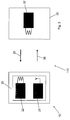
- FIG. 3 is a schematic representation of the mobile identification transmitter 10 is shown.
- the communication means 20 is arranged.
- This communication means 20 has a transmitting means 21 and a receiving means 22.
- the external data device 30 is arranged.
- the external data device may be an information chip, such as an RFID chip.
- the communication means 20 can be used in various modes.
- An energy emitting active mode 110 is recorded.
- the transmission means 21 of the communication means 20 generates a high-frequency alternating electromagnetic field which illuminates the reception element 32 of the external data device 30.
- An induction current is produced in an antenna coil of the receiving element 32.
- This induction current can be used to operate a computing element within the external data device.
- the computer element activated in this way can receive commands and / or information from the communication device 20. These commands and / or information are processed in the computing element which generates a response therefrom.
- This response is sent as part of a data transfer 25 from the receiving element 32 to the communication means 20.
- the receiver 22 serves as the receiver.
- the answer is generated in that the receiving element 32 weakens the electromagnetic alternating field radiated by the transmitter 21 as part of an energy transfer 26. This weakening is characteristic and involves the response of the external data device 30.
- the communication means 20 transmits the energy that the external data device 30 uses to establish a data transfer 25.
- the active mode 110 has been found to be particularly advantageous if predetermined information is to be read out by means of the communication means 20.
- the data device 30 is often non-active systems whose job is to provide pre-set information - such as serial numbers, etc. - for readout.
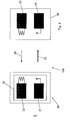
- FIG. 4 a further embodiment variant of the identification transmitter 10 according to the invention is shown.
- the identification transmitter 10 is operated in a passive mode 100.
- This passive mode 100 is characterized in that an energy transfer 26 takes place from the external data device 30 '.
- the mobile identification transmitter 10 does not transmit the energy, but receives it from the external data device 30 '. Consequently, in the external data device 30 ', a transmission element 31 must be arranged, which emits a high-frequency alternating electromagnetic field in order to enable the energy transfer 26.
- the communication means 20 recognizes and uses this energy transfer 26. Consequently, the communication means 20 switches in the passive mode 100.
- the receiving means 22 thereby modulates the field strength of the high-frequency alternating electromagnetic field emitted by the transmitting element 31 in the context of the energy transfer 26. This already described in the context of the active mode 110 damping of Electromagnetic field is used in passive mode 100 to read information from the communication means 20.
- the passive mode 100 and the active mode 110 thus differ in the direction of the energy transfer 26. If this takes place from the communication means 20 to an external device 30, it is an active mode 110. On the other hand, the external data device 30 'emits energy the communication means 20, this uses the passive mode 100.
- a third mode - the so-called transmission mode 120 - a data transfer 25, 25 'between the communication means 20 and an external data device 30' take place.
- This transmission mode 120 is in the FIG. 5 shown.
- no energy transfer 26 takes place insofar as the respectively transmitted electromagnetic waves are used exclusively for the information flow.
- the transmitting means 21 of the communication means 20 transmits an exemplary amplitude or frequency modulated electromagnetic wave 25 'to the transmitting element 31 of the external data device 30'.
- a computer element can evaluate the received information and provide retrieved data and / or information for transmission to the communication means 20.
- the transmitting element 31 is used for this purpose, which in turn modulates electromagnetic waves and transmits them as part of the data transfer 25 to the communication means 20.
- the receiving means 22 of the communication means 20 receives the data thus transmitted in the context of the data transfer 25 and makes them available to the computer unit within the mobile identification transmitter 10.
- the inventive mobile identification transmitter 10 thus has three modes: the active, the passive and the transmission mode.
- the mobile identification transmitter 10 is designed such that the communication means 20 can be activated at any time in one of the three modes.
- the communication means 20 is designed to respond to external conditions. So can in about the same time intervals of active mode 110 are turned on and the communication element 20 make an energy transfer 26. This can happen regardless of whether an external data device 30, 30 'at a distance of less than 10 cm in the mobile identification transmitter 10 is arranged.
- the three modes allow the communication means 20 and thus the mobile identification transmitter 10 with a variety of differently designed external data devices 30, 30 'in contact. This ensures that the mobile identification transmitter 10 can be used for a large number of applications.
- the mobile identification transmitter 10 can perform either the data transfer 25, 25 'or the communication 42 with the motor vehicle 40. This is to prevent interference between the two electromagnetic signals. It has proved to be advantageous if the communication means is blocked upon activation of the transmitting and receiving unit 13 and if the transmitting and receiving unit 13 is blocked upon activation of the communication means. For example, a vehicle user actuates the actuating element 15 'of the in FIG. 2 shown mobile identification transmitter 10, this can lead to an activation of the communication means 20. If an external data device 30 is within a range of up to 10 cm, the data transfer 25 takes place.
- a computer program within the computer unit of the mobile identification transmitter 10 could prevent a communication 42 from being established to the vehicle 40.
- the energy supply of the transmitting and receiving unit 13 could be interrupted by way of example If, in turn, the vehicle receiver wishes to authenticate itself to its motor vehicle and actuates one of the two actuating elements 15, 15 ", this would result in a communication 42 with the vehicle 40. During this time, it would not be possible to establish a data transfer 25 with the external data device 30. This variant has increased security for the Users, since no interference between the data transfer 25 and the communication 42 may occur.
- the identification device 10 enables a data transfer 25 within a near range of up to 10 cm. This results in a variety of advantages. Thus, listening to the data transmitted in the context of data transfer 25 is almost impossible. Furthermore, it requires the voluntary activation of the data transfer 25, which can not happen by chance. Rather, the mobile identification transmitter 10 must always be placed in the reception area of the external data device 30, which is not more than 10 cm.
Landscapes
- Physics & Mathematics (AREA)
- General Physics & Mathematics (AREA)
- Engineering & Computer Science (AREA)
- Mechanical Engineering (AREA)
- Lock And Its Accessories (AREA)
Description
- Die Erfindung betrifft einen mobilen Identifikationsgeber eines Sicherheitssystems für eine schlüssellose Aktivierung einer Schließvorrichtung eines Kraftfahrzeuges gemäß des Oberbegriffes des Anspruches 1, mit einem Gehäuse, in dem eine Elektronikeinheit mit wenigstens einer Sende- und Empfangseinheit angeordnet ist, die Sende- und Empfangseinheit mit einer kraftfahrzeugseitigen Verbindungseinheit über eine erste Kommunikationsverbindung mittels elektromagnetischer Wellen in Verbindung steht, mit Hilfe derer eine Identifikationsprüfung zur Feststellung einer Benutzerberechtigung durchführbar ist.
- Mobile Identifikationsgeber werden bei zahlreichen Anwendungen bei Kraftfahrzeugen zur Erhöhung des Bedienerkomforts eingesetzt. So kann ein berechtigter Benutzer aktiv den Identifikationsgeber betätigen, um ein Signal zur Basisstation, beispielsweise an eine im Kraftfahrzeug vorgesehene Elektronikeinheit, zum Öffnen des Fahrzeuges übermitteln.
- Um einen hohen Bedienungskomforts zu erreichen, weisen mobile Identifikationsgeber Sende- und Empfangseinheiten auf, die eine langreichweitige Verbindung mit kraftfahrzeugseitigen Verbindungseinheiten ermöglichen. Als nachteilig hat es sich dabei herausgestellt, dass weitere Funktionen des mobilen Identifikationsgebers auch über diese langreichweitigen Sende- und Empfangseinheiten übermittelt werden. Dieses führt dazu, dass auch sicherheitsrelevante Anweisungen an das Kraftfahrzeug über eine weite Distanz übermittelt werden können. Folglich akzeptiert das Kraftfahrzeug auch sicherheitsrelevante Anweisungen, die aus großer Entfernung abgesendet worden. Dadurch ist es möglich, dass sicherheitsrelevante Funktionen - wie etwa ein Deaktivieren eines Airbags - durch einen unbeabsichtigten Zufall ausgelöst werden können.
- Ein mobiler Identifikationsgeber ist aus der
DE 10 2004 050846 A1 bekannt, der nur eine Sende- und Empfangseinheit aufweist, deren Sendeleistung moduliert werden kann, um verschiedene Verbindungen mit unterschiedlichen Reichweiten herzustellen. Dabei hat sich als ein Nachteil herausgestellt, dass die Übertragung sicherheitsrelevanter Daten von der Übertragung der Identifikationsdaten nicht sicher getrennt werden kann, da beide Übertragungen durch eine Sende-/Empfangseinheit ausgeführt werden - Weitere Beispiele von mobilen ldentifikationsgebern sind aus den
US 2006/0219776 A1 undWO 00/12845 A1 - Aufgabe der vorliegenden Erfindung ist es, einen mobilen Identifikationsgeber bereitzustellen, welcher die oben genannten Nachteile überwindet, insbesondere einen mobilen Identifikationsgeber zu schaffen, mit dem eine erhöhte Sicherheit innerhalb des Betriebes erreichbar ist.
- Diese Aufgabe wird durch einen mobilen Identifikationsgeber eines Sicherheitssystems für eine schlüssellose Aktivierung einer Schließvorrichtung eines Kraftfahrzeuges mit den Merkmalen des Anspruches 1 in vorteilhafter Weise gelöst. Weitere vorteilhafte Ausführungsformen der vorliegenden Vorrichtungen ergeben sich aus den jeweiligen Unteransprüchen. Dabei können die in den Ansprüchen und in der Beschreibung erwähnten Merkmale jeweils einzeln für sich oder in beliebiger Kombination erfindungswesentlich sein.
- Der erfindungsgemäße mobile Identifikationsgeber zeichnet sich dadurch aus, dass die Elektronikeinheit ein Kommunikationsmittel aufweist, um einen Datentransfer über eine zweite Kommunikationsverbindung mittels elektromagnetischer Wellen mit einem externen Datengerät ausschließlich bis zu einer Reichweite von bis zu 10 cm zu ermöglichen, wobei das Kommunikationsmittel nach einem NFC Standard arbeitet, wobei der mobile Identifikationsgeber ein Schaltelement aufweist, und wobei mittels des Schaltelements alternativ die Sende- und Empfangseinheit oder das Kommunikationsmittel aktivierbar und/oder blockierbar sind.
- Der Kern der Erfindung besteht darin, den mobilen Identifikationsgeber mit einem Kommunikationsmittel auszurüsten. Dieses Kommunikationsmittel ermöglicht einen Datentransfer bis zu einer Reichweite von weniger als 10 cm. Somit weist der mobile Ident'rfikationsgeber zwei Elemente auf, die zum Senden bzw. Empfangen von Informationen ausgelegt sind. Zum einen ist in dem mobilen Identffikationsgeber die Sende- und Empfangseinheit integriert, die dazu dient, eine Authentifizierung des mobilen Ident'rfikationsgebers gegenüber dem Fahrzeug zur erreichen. Zusätzlich ist das Kommunikationsmittel in dem mobilen Identifikationsgeber integriert. Über das Kommunikationsmittel können andere, auch sicherheitsrelevante Informationen im Rahmen eines Datentransfers mit einem externen Datengerät ausgetauscht werden. So ist es beispielhaft denkbar, dass das externe Datengerät in dem Kraftfahrzeug integriert ist und über das Kommunikationsmittel beispielhaft der Airbag aktiviert oder deaktiviert werden kann. Ausschlaggebend für die Überwindung der oben genannten Nachteile ist es, dass die Reichweite des Kommunikationsmittels klar begrenzt ist. Die erfindungsgemäße Reichweite, über die ein Datentransfer möglich ist, ist auf ca. 10 cm begrenzt. Weist der mobile Identifikationsgeber einen Abstand von dem externen Datengerät auf, der größer ist als 10 cm, so ist ein Datentransfer zwischen dem Kommunikationsmittel und dem externen Datengerät nicht mehr möglich. Folglich können auch Fehlbedienungen des mobilen Identifikationsgebers nicht zu sicherheitsrelevanten Zwischenfällen führen. Dieses Merkmal des mobilen Identifikationsgebers verhindert weiterhin ein unberechtigtes Abhören der über dem Datentransfer übermittelten Daten. So ist es einem unberechtigten Dritten nicht möglich, Informationen, die mittels des Kommunikationsmittels an das externe Datengerät übermittelt werden, abzuhören. Denn dazu müsste der unberechtigte Dritte innerhalb der Übertragungsreichweite von bis zu 10 cm an das Kommunikationsmittel heran gelangen.
- In einer vorteilhaften Variante der Erfindung ist vorgesehen, dass das Kommunikationsmittel nach einem NFC Standard (Near Field Communication) arbeitet. Die NFC-Technologie ist eine kontaktlose, induktive Verbindungstechnologie. Sie arbeitet in einem Frequenzbereich von 13,56 MHz und bietet eine Datenübertragungsrate von maximal 424 kBit/s bei einer Reichweite von bis zu 10 Zentimetern. Die NFC-Technologie ist durch ISO (Internationale Organisation für Normung) 18092, 21481 ECMA 340, 352, 356, 362 beziehungsweise ETSI (Europäische Institut für Telekommunikationsnormen) TS 102 190 standardisiert. Die NFC-Technologie ist kompatibel mit verwendeter Smart Card-Infrastruktur basierend auf ISO/IEC 14443A (z. B. NXP's Mifare-Technologie) wie auch mit Sonys FeliCa-Card, die für elektronische Fahrkarten im öffentlichen Nahverkehr und für Zahlungsanwendungen genutzt werden.
- Eine weitere vorteilhafte Ausgestaltung sieht vor, dass das Kommunikationsmittel ein Sendemittel und ein Empfangsmittel aufweist. Um dem Kommunikationsmittel eine Reichweite von weniger als 10 cm zu ermöglichen, weist das Kommunikationsmittel die Sende- und Empfangsmittel auf. Mittels des Sendemittels können vorzugsweise elektromagnetische Wellen ausgesandt werden, die von dem externen Datengerät empfangen werden. Das Empfangsmittel dient hingegen dazu, elektromagnetische Wellen zu empfangen und an eine Rechnereinheit innerhalb des Kommunikationsmittels weiterzuleiten. Die Rechnereinheit dient dazu, die im Rahmen des Datentransfers empfangenen Informationen auszuwerten und/oder darzustellen. Gleichfalls werden mittels der Rechnereinheit die Informationen derart verarbeitet, dass das Sendemittel diese übermitteln kann. Neben der besagten NFC-Technologie kann das Sendemittel und/oder Empfangsmittel auch noch eine der folgenden Technologien verwenden: USB-Interface (Universal Serial Bus), SPI (Serial Peripheral Interface), 12C (Inter-Integrated Circuit), UART (Universal Asynchronous Receiver Transmitter) serial link, wireless USB-Interface. Ausschlaggebend dabei ist, dass die Reichweite der genannten Technologien auf 10 cm begrenzt ist oder wird. Somit können Datentransfers nur innerhalb dieser Reichweite ermöglicht werden.
- Eine weitere, die Erfindung verbessernde Maßnahme sieht vor, dass der Datentransfer ein uni- und/oder bidirektionales Empfangen und/oder Senden von Daten beinhaltet.
- In einer vorteilhaften Variante der Erfindung ist vorgesehen, dass das Kommunikationsmittel
- einen energieabsorbierenden passiven Modus aufweist, wobei durch eine Dämpfung einer empfangenen Energie einen Datentransfer ausführbar ist, und
- einen energieemittierenden aktiven Modus aufweist, wobei eine Dämpfung einer vom Kommunikationsmittel emittierten Energie im externen Datengerät zu einem Datentransfer an das Kommunikationsmittel führt.
- Im Rahmen des energieemittierenden aktiven Modus sendet das Sendemittel des Kommunikationsmittels ein hochfrequentes elektromagnetisches Wechselfeld aus, welches ein Empfangselement des externen Datengerätes beleuchtet. In einer Antennenspule des Empfangselementes entsteht - sobald diese in den Bereich des elektromagnetischen Feldes kommt - ein Induktionsstrom. Der Strom wird gleichgerichtet und genutzt um einen Kondensator als Kurzzeitspeicher aufzuladen, welcher im Rahmen des Datentransfers für die Stromversorgung des externen Datengerätes genutzt wird. Das so aktivierte externe Datengerät empfängt entweder über das elektromagnetische Wechselfeld oder ein parallel geschaltetes Informationsfeld einen Befehl des Kommunikationsmittels. Als besonders vorteilhaft hat es sich herausgestellt, wenn diese Befehle in das elektromagnetische Wechselfeld, welches von dem Sendemittel ausgesandt wird, einmoduliert werden. Das externe Datengerät nutzt den induzierten Strom um ein Rechnerelement zu betreiben, welches die Antwort auf die Anfrage des mobilen Identifikationsgebers generiert. Anschließend wird durch eine Feldschwächung im kontaktfreien Kurzschluss oder per Reflexion die Antwort auf das vom Kommunikationsmittel emittierten elektromagnetischen Feldes aufmoduliert. Im Rahmen dieser Antwort kann das externe Datengerät eine Mehrzahl von Informationen übermitteln. Somit ist das externe Datengerät passiv und weist keine eigene Energiequelle auf. Vielmehr nutzt das externe Datengerät die von dem Kommunikationsmittel übersandte Energie um den Datentransfer durchzuführen. Der Datentransfer ist in dem dargestellten Beispiel bidirektional. Denn das Kommunikationsmittel übersendet durch Modulation des elektromagnetischen Wechseffeldes eine Anfrage an das externe Datengerät. Auf Basis dieser Anfrage wird dann eine Antwort übermittelt.
- Weiterhin weist das Kommunikationsmittel die Möglichkeit auf, den energieabsorbierenden passiven Modus zu nutzen. Dabei nutzt das Kommunikationsmittel ein elektromagnetisches Wechselfeld, welches von dem externen Datengerät in das Empfangsmittel eingestrahlt wird. Folglich sind das Verhalten des Kommunikationsmittels und des externen Datengerätes im aktiven Modus getauscht zu jenen im passiven Modus.
- Eine weitere vorteilhafte Ausgestaltung sieht vor, dass das Kommunikationsmittel einen energleemittierenden Sendemodus aufweist, zum Empfangen und Senden von Daten. Der energieemittierende Sendemodus unterscheidet sich von dem passiven und aktiven Modus dadurch, dass das Empfangselement empfangene elektromagnetische Wellen nicht dazu nutzt, um einen Energievorrat für einen Datentransfer aufzubauen. Vielmehr werden aus den im Rahmen des Datentransfers empfangenen elektromagnetischen Wellen nur Informationen generiert. Parallel dazu wird das Sendemittel auch nur zur Übersendung von Informationen genutzt. Die abgestrahlten elektromagnetischen Wellen dienen nicht dazu, ein externes Datengerät mit Energie zu versorgen.
- Eine weitere, die Erfindung verbessernde Maßnahme sieht vor, dass der Datentransfer mit dem externen Datengerät in dem passiven Modus und/oder dem aktiven Modus und/oder dem Sendemodus ausführbar ist.
- In einer vorteilhaften Variante der Erfindung ist vorgesehen, dass das Kommunikationsmittel innerhalb eines Frequenzbereiches f arbeitet, der zwischen 10 MHz ≤ f ≤ 15 MHz liegt, insbesondere dass das Kommunikationsmittel innerhalb eines Frequenzbereiches f um 13.56 MHz arbeitet.
- Eine weitere vorteilhafte Ausgestaltung sieht vor, dass die Sende- und Empfangseinheit mit der kraftfahrzeugseitigen Verbindungseinheit einen Informationstransfer bis zu einer Reichweite von bis zu 300 m, bevorzugt bis zu 200 m ermöglicht.
- Eine weitere, die Erfindung verbessernde Maßnahme sieht vor, dass bei einer Aktivierung der Sende- und Empfangseinheit das Kommunikationsmittel blockiert ist. Erfindungsgemäß ist vorgesehen, dass das Kommunikationsmittel im Rahmen des Datentransfers keine Informationen an das externe Datengerät übermitteln kann, wenn die Sende- und Empfangseinheit aktiviert ist, Unter Aktivierung ist dabei zu verstehen, dass ein Nutzer des mobilen Identifikationsgebers einen entsprechenden Befehl an die Sende-und Empfangseinheit übermittelt hat, so dass diese in Verbindung mit der kraftfahrzeugseitigen Verbindungseinheit steht. Davon umfasst sind auch sämtliche Übermittlungen von Daten durch die Sende- und Empfangseinheit an Dritte Einrichtungen, wie etwa Werkstätten etc. Durch die Blockierung des Kommunikationsmittels ist sichergestellt, dass es keine Interferenzen zwischen den mittels der Sende- und Empfangseinheit ausgesandten Informationen und den vom Kommunikationsmittel ausgestrahlten Daten gibt. Die Blockierung des Kommunikationsmittels kann dabei auf mehrere Arten geschehen. So kann zum einen die Energieversorgung des Kommunikationsmittels für jenen Zeitraum unterbrochen werden, in dem die Sende- und Empfangseinheit aktiv ist. Denkbar ist es auch, dass ein Senden und/oder Empfangen von Informationen mittels der Sende- und Empfangseinheit dazu führt, dass ein entsprechendes Signal von einer Rechnereinheit der Elektronikeinheit generiert wird. Dieses Signal führt dazu, dass das Kommunikationsmittel keinen Datentransfer mit einem externen Datengerät akzeptiert und/oder auslöst.
- In einer vorteilhaften Variante der Erfindung ist vorgesehen, dass bei einer Aktivierung des Kommunikationsmittels die Sende- und Empfangseinheit blockiert ist. Im Rahmen dieser Ausführungsvariante ist vorgesehen, dass die Sende- und Empfangseinheit keine Verbindung mit der fahrzeugseitigen Verbindungseinheit aufnehmen kann, wenn das Kommunikationsmittel im Datentransfer mit dem externen Datengerät besteht. Unter dem Ausdruck "blockiert" soll im Rahmen der Erfindung verstanden werden, dass es nicht möglich ist, mittels der Sende- und Empfangseinheit elektromagnetische Wellen auszustrahlen. Diese Blockierung kann durch verschiedene Vorgehensweisen erreicht werden. So kann eine Rechnereinheit innerhalb der Elektronikeinheit dafür sorgen, dass ein - wie auch immer gearteter - Aktivierungsbefehl nicht an die Sende- und Empfangseinheit weitergeleitet wird. Dazu kann ein entsprechendes Computerprogramm in der Rechnereinheit ablaufen. Denkbar ist es aber auch, dass bei einer Aktivierung des Kommunikationsmittels die Energieversorgung der Sende- und Empfangseinheit unterbrochen wird. Dadurch ist sichergestellt, dass trotz eines entsprechenden Befehles an die Sende- und Empfangseinheit diese keine elektromagnetischen Wellen aussenden kann.
- Der mobile ID-Geber kann durch die Kombination der NFC-Technologie mit der bereits vorhandenen Funkfernbedienungs-HF-Technologie in seiner Funktion erweitert werden. So kann eine Umschaltung der Reichweite von Nah- auf Fern ist entsprechend der gewünschten Reichweite der Funktion vorgesehen sein. Der mobile ID-Geber kann einerseits die durch die NFC bedingte Reichweite von max. 10 Zentimetern im Nahfeld nutzen und damit eine unerwünschte Fehlbedienung ausschließen. Andererseits kann die Funkstrecke auch Funktionen bis zu einer Reichweite von mehreren Hundert Metern ermöglichen. So könnte z.B. die bewusste Abschaltung des Airbags durch die Nahfeld-Funktion aktiviert werden. Für eine Bezahlfunktion ist die Reichweitenbeschränkung ebenfalls wichtig. Andererseits können über die Nahfeld-Strecke übertragene Daten dem Fahrzeug über die Funkfernbedienungs-Übertragungsstrecke übermittelt werden.
- Eine weitere vorteilhafte Ausgestaltung der Erfindung zeichnet sich dadurch aus, dass jeweils nur die Sende- und Empfangseinheit oder das Kommunikationsmittel zu einem Zeitpunkt genutzt werden können. Dadurch ist sichergestellt, dass keine Interferenzen zwischen dem Datentransfer des Kommunikationsmittels und der Verbindung der Sende-und Empfangseinheit auftreten. So kann der erfindungsgemäße mobile Identifikationsgeber entweder mit der fahrzeugseitigen Verbindungseinheit in Kontakt treten oder einen Datentransfer mit dem externen Datengerät ausführen. Diese Variante hat den Vorteil, dass insbesondere Datentransfers mit sicherheitsrelevanten Datengeräten nicht durch die Sende- und Empfangseinheit gestört werden können. Es bedarf vielmehr einer aktiven Auslösung des Kommunikationsmittels, die zu einer Deaktivierung und/oder Blockierung der Sende- und Empfangseinheit führt. Gleiches gilt auch im Gegenzug, wenn der Nutzer des mobilen Identifikationsgebers einen Steuerbefehl an das Sicherheitssystem der Schließvorrichtung des Kraftfahrzeuges übermittelt. Auch in diesem Falle ist sichergestellt, dass das Kommunikationsmittel keinen Datentransfer beginnt und/oder ausführt.
- Eine weitere vorteilhafte Ausgestaltung sieht vor, dass der mobile Identifikationsgeber ein Schaltelement aufweist, wobei mittels des Schaltelements alternativ die Sende- und Empfangseinheit oder das Kommunikationsmittel aktivierbar und/oder blockierbar sind. Das Schaltelement sorgt dafür, dass zu einem Zeitpunkt immer nur die Sende- und Empfangseinheit oder das Kommunikationsmittel in Betrieb sind. Für die Ausgestaltung des Schaltelementes besteht eine Vielzahl von Möglichkeiten. So kann es sich bei dem Schaltelement um ein Computerprogramm handeln, welches auf der Rechnereinheit der Elektronikeinheit abläuft. Wird die Sende- und Empfangseinheit ausgelöst, so führt dieses zu einer Auslösung des Schaltelementes, also des Computerprogramms. Jenes Computerprogramm kann das Kommunikationsmittel blockieren und/oder eine Stromversorgung zu dem Kommunikationsmittel unterbrechen. Alternativ ist es auch möglich, dass das Schaltelement ein händisch zu bedienender Schalter ist, der von einem Nutzer aktiviert werden muss, um in Anschluss die Sende- und Empfangseinheit oder das Kommunikationsmittel zu bedienen. Somit kann die Verbindung zu dem Kraftfahrzeug oder der Datentransfer zu dem externen Datengerät nur dann aufgebaut werden, wenn der Nutzer im Vorhinein das Schaltelement betätigt hat. Eine weitere, die Erfindung verbessernde Maßnahme sieht vor, dass das Schaltelement in der Elektronikeinheit und/oder in dem Gehäuse und/oder an dem Gehäuse angeordnet ist.
- In einer vorteilhaften Variante der Erfindung ist vorgesehen, dass der mobile Identifikationsgeber ein Display aufweist, wobei insbesondere mittels des Displays der Datentransfer und/oder eine Information, die den Datentransfer betrifft, anzeigbar sind.
- Eine weitere vorteilhafte Ausgestaltung sieht vor, dass das Display mindestens eines der folgenden Mittel verwendet: eine Leuchtdiode (LEDs), eine Organische Leuchtdiode (OLEDs), eine Flüssigkristallanzeige (LCDs), einen Plasmabildschirm, eine Kathodenstrahlröhre, ein Surface-Conduction Electron-Emitter Display (SED) oder einen Feldemissionsbildschirm (FED).
- Eine weitere, die Erfindung verbessernde Maßnahme sieht vor, dass die Elektronikeinheit und/oder die Sende- und Empfangseinheit und/oder das Kommunikationsmittel zumindest eine der folgenden Technologien aufweisen: Wireless LAN (IEEE 802.11), FireWire (IEEE 1394), USB (Universal Serial Bus), HDMI (High Definition Multimedia Interface), IrDA (Infrared Data Association), Bluetooth, Unilink, ATA/ATAPI (Advanced Technology Attachment with Packet Interface), IEEE 488, IEEE 1284, Bidirektionale Funkstrecke, Near Field Communication (NFC), induktive Übertragung, SPI, I2C, UART serial link oder wireless USB-Interface.
- In einer vorteilhaften Variante der Erfindung ist vorgesehen, dass mittels des Kommunikationsmittels eine Datenverbinduhg zum Internet aufbaubar ist. Erfindungsgemäß können im Rahmen des Datentransfers eine Vielzahl von Informationen an ein externes Datengerät gesandt werden oder von diesem empfangen werden. So kann das Kommunikationsmittel beispielhaft dazu genutzt werden, um Authentifizierungsinformationen für ein Bezahlgerät zu übermitteln. Das Bezahlgerät kann z. B. dazu dienen, eine Fahrkarte für einen Nahverkehrsmittel auszugeben. Ein Nutzer des mobilen Identifikationsgebers kann sich folglich in die direkte örtliche Nähe zu dem Bezahlgerät begeben, eine entsprechende Aktivierung auslösen und dadurch eine Fahrkarte erwerben. Denkbar ist es auch, dass sicherheitsrelevante Systeme - wie ein Zu- und/oder Abschalten eines Airbags oder ESP - durch den Datentransfer ausgelöst werden. Weitere mögliche Funktionen, die mittels des Kommunikationsmittels ausgeführt werden, sind:
- Übertragung von MP3 Musikdaten von einem NFC-Gerät (z.B. Handy, MP3-Player) zu einem Fahrzeug Infotainment-Gerät,
- Aktivierung eines Parkplatzzugangssystems, Sperrung eines Handschuhkastens oder eines Kofferraumes, und
- ein GPS-Datentransfer von dem Fahrzeug in den mobilen Identifikationsgeber, sowie gegebenenfalls in ein GPS-Handy.
- Im Rahmen einer weiteren Ausführungsvariante ist es möglich, dass Positionsangaben von einem satellitengestützten Navigationssystem - z. B. GPS (Global Positioning System) - über das Kommunikationsmittel auf den mobilen Identifikationsgeber übertragen werden. Dort ist eine Speicherung dieser Positionsangaben möglich, die gegebenenfalls auf dem Display angezeigt werden können. Diese Eigenschaft hat sich insbesondere dann als vorteilhaft erwiesen, wenn der Standort des Kraftfahrzeugs ermittelt werden soll. Um diese Funktion sicherzustellen, wird der mobile Identifikationsgeber an ein GPS-Datengerät, wie es beispielhaft in Kraftfahrzeugen integriert ist, angenähert, so dass über das Kommunikationsmittel im Rahmen des Datentransfers die Positionsangaben übermittelt werden können. Neben der beschriebenen Eigenschaft kann der mobile Identifikationsgeber auch von einem zweiten, nicht in dem Fahrzeug integrierten GPS-Datengerät Positionsangaben empfangen. So kann beispielhaft in ein Mobiltelefon ein GPS-System eingebaut sein. Über das erfindungsgemäß beschriebene Kommunikationsmittel ist ein Datenaustausch mit dem Mobiltelefon möglich. Im Rahmen dieses Datenaustausches können GPS-Positionsangaben von dem Mobiltelefon an den mobilen Identifikationsgeber übertragen werden. Durch einen Vergleich des mit dem Mobiltelefon ermittelten aktuellen Standortes und des Standorts des Kraftfahrzeugs kann der Besitzer des mobilen Identifikationsgebers zu dem Kraftfahrzeug geführt werden. Dieses ermöglicht ein schnelles und unkompliziertes Auffinden des Kraftfahrzeugs an beliebigen Orten.
- Weitere Vorteile, Merkmale und Einzelheiten der Erfindung ergeben sich aus der nachfolgenden Beschreibung, in der unter Bezugnahme auf die Zeichnungen Ausführungsbeispiele der Erfindung im Einzelnen beschrieben sind. Dabei können die in den Ansprüchen und in der Beschreibung erwähnten Merkmale jeweils einzeln für sich oder in beliebiger Kombination erfindungswesentlich sein. Es zeigen:
- Fig. 1
- eine schematische Ansicht des erfindungsgemäßen Sicherheitssystems mit einem mobilen Identifikationsgeber und einer Schließvorrichtung eines Kraftfahrzeuges,
- Fig. 2
- den erfindungsgemäßen mobilen Identifikationsgeber in einem Datentransfer mit einem externen Datengerät,
- Fig. 3
- eine weitere Ausführungsvariante des Datentransfers zwischen dem mobilen Identifikationsgeber und dem externen Datengerät,
- Fig. 4
- eine weitere Ausführungsvariante des Datentransfers zwischen dem mobilen Identifikationsgeber und dem externen Datengerät und
- Fig. 5
- eine weitere Ausführungsvariante des Datentransfers zwischen dem mobilen Identifikationsgeber und dem externen Datengerät.
- In
Fig. 1 ist ein mobiler Identifikationsgeber 10 eines Sicherheitssystems für eine schlüssellose Aktivierung einer Schließvorrichtung 43 eines Kraftfahrzeuges 40 dargestellt. Der Identifikationsgeber 10 ist mit einem Gehäuse ausgeführt, in dem eine Elektronikeinheit 12 mit einer Sende- und Empfangseinheit 13 angeordnet ist. Der mobile Identifikationsgeber 10 kann über die Sende- und Empfangseinheit 13 eine Verbindung 42 - im Folgenden auch Kommunikation - mit einer fahrzeugseitigen Verbindungseinheit 41 aufbauen. Über die Kommunikation 42 werden dabei sicherheitsrelevante Informationen ausgetauscht, die zur Authentifizierung des mobilen Identifikationsgebers 10 dient. Im Rahmen der Verbindung 42 können insbesondere Codes und/oder Schlüssel uni und/oder bidirektional übertragen werden. Ziel ist es, dass das Kraftfahrzeug 40 die Berechtigung des mobilen Identifikationsgebers 10 überprüft. Sobald festgestellt ist, dass der mobile Identifikationsgeber 10 berechtigt ist, ein Ver- und/oder Entriegeln an dem Kraftfahrzeug auszulösen, wird ein entsprechendes Signal an die Schließvorrichtung 43 übermittelt, um damit ein Öffnen bzw. Verschließen des Kraftfahrzeuges auszulösen. - Ein erfindungsgemäß ausgestalteter mobiler Identifikationsgeber 10 ist in
Figur 2 dargestellt. Der mobile Identifikationsgeber 10 weist ein Gehäuse 11 auf. Innerhalb des Gehäuses 11 ist eine Elektronikeinheit 12 integriert. Die Elektronikeinheit 12 dient zur Überwachung der mit dem mobilen Identifikationsgeber 10 gesteuerten Informationen. Um dieses sicherzustellen, hat es sich als vorteilhaft herausgestellt, wenn der mobile Identifikationsgeber 10 einen Datenspeicher aufweist. Dieser Datenspeicher kann in der Elektronikeinheit 12 integriert sein. Um eine entsprechende Versorgung mit Energie sicherzustellen, weist der mobile Identifikationsgeber 10 auch einen Energiespeicher auf. Dabei hat es sich als vorteilhaft herausgestellt, wenn es sich dabei um einen wiederaufladbaren Energiespeicher handelt. Des Weiteren ist in die Elektronikeinheit 12 eine Rechnereinheit integriert. Auf der Rechnereinheit kann ein Computerprogramm laufen. Bei der Rechnereinheit handelt es sich vorzugsweise um ein FPGA (Field Programmable Gate Array), einen Mikrocontroller oder einen andersartig ausgestalteten integrierten Schaltkreis. - Wie die
Figur 2 verdeutlicht, ist ein Teil der Elektronikeinheit 12 die Sende- und Empfangseinheit 13. Sie dient zum Aufbau der Kommunikation 42 mit dem Kraftfahrzeug 40. In dem dargestellten Ausführungsbeispiel ist die Sende- und Empfangseinheit 13 an einer der Seitenflächen des Gehäuses 11 angeordnet. Um die oben aufgeführten Nachteile zu überwinden, weist die Elektronikeinheit 12 ein Kommunikationsmittel 20 auf. Dieses ist ebenfalls in dem Gehäuse 11 des mobilen Identifikationsgebers 10 angeordnet. Das Kommunikationsmittel 20 ermöglicht einen Datentransfer 25 an ein externes Datengerät 30 ausschließlich bis zu einer Reichweite von bis zu 10 cm. Um diesen Datentransfer 25 zu ermöglichen, kann das Kommunikationsmittel 20 über ein Sendemittel 21 und ein Empfangsmittel 22 verfügen. - Um den Datentransfer 25 auszulösen, hat es sich als vorteilhaft erwiesen, wenn der mobile Identifikationsgeber 10 ein entsprechend ausgestaltetes Betätigungselement aufweist. In dem dargestellten Ausführungsbeispiel sind in das Gehäuse 11 des mobilen Identifikationsgebers 10 drei Betätigungselemente 15, 15', 15" integriert. Die Betätigungselemente 15, 15" dienen zum Auslösen einer schlüssellosen Aktivierung der Schließvorrichtung 43 des Kraftfahrzeuges 40. Entsprechend ausgestaltete Piktogramme dienen zur Verdeutlichung der Funktion. An dem Betätigungselement 15 ist eine Entriegelung der Schließvorrichtung 43 auslösbar. Ein entsprechender Befehl wird von der Elektronikeinheit 12 generiert und über die Sende- und Empfangseinheit 13 an das Kraftfahrzeug 40 übermittelt. Möchte ein Benutzer im Gegenzug das Kraftfahrzeug 40 verriegeln, genügt eine Betätigung des Betätigungselementes 15". Befindet sich der Benutzer in einer örtlichen Nähe zu dem externen Datengerät 30, wird durch eine Betätigung des Betätigungselementes 15' eine Datentransfer 25 ausgelöst. Zusätzlich kann in dem Gehäuse 11 des mobilen Identifikationsgebers 10 noch ein Display integriert sein. In dem in
Figur 2 gezeigten Ausführungsbeispiel ist dieses nicht eingezeichnet. Das Display kann dazu dienen, Daten, die an und/oder von dem mobilen Identifikationsgeber 10 übermittelt werden, visuell darzustellen. Als vorteilhaft hat es sich herausgestellt, wenn es sich bei dem Display um eine Flüssigkristallanzeige und/oder einem Plasmabildschirm handelt. - In
Figur 3 ist eine schematische Darstellung des mobilen Identifikationsgebers 10 dargestellt. Innerhalb des mobilen Identifikationsgebers 10 ist das Kommunikationsmittel 20 angeordnet. Dieses Kommunikationsmittel 20 weist ein Sendemittel 21 und ein Empfangsmittel 22 auf. In örtlicher Nähe, also innerhalb einer Reichweite von weniger als 10 cm, ist das externe Datengerät 30 angeordnet. Bei dem externen Datengerät kann es sich beispielhaft um einen Informationschip, wie etwa ein RFID Chip handeln. Auf solcher Art ausgestalteten externen Datengeräten 30 können Informationen wie Seriennummern etc. gespeichert werden. Erfindungsgemäß kann das Kommunikationsmittel 20 in verschiedenen Modi eingesetzt werden. InFigur 3 ist ein energieemittierender aktiver Modus 110 aufgezeichnet. Dabei erzeugt das Sendemittel 21 des Kommunikationsmittels 20 ein hochfrequentes elektromagnetisches Wechselfeld, welches das Empfangselement 32 des externen Datengerätes 30 beleuchtet. In einer Antennenspule des Empfangselementes 32 entsteht ein Induktionsstrom. Dieser Induktionsstrom kann genutzt werden, um ein Rechnerelement innerhalb des externen Datengerätes zu betreiben. Das so aktivierte Rechnerelement kann von dem Kommunikationsmittel 20 Befehle und/oder Informationen empfangen. Diese Befehle und/oder Informationen werden in dem Rechnerelement verarbeitet, welches daraus eine Antwort erzeugt. Diese Antwort wird im Rahmen eines Datentransfers 25 von dem Empfangselement 32 an das Kommunikationsmittel 20 übersandt. Als Empfänger dient dabei das Empfangsmittel 22. Die Antwort wird dadurch erzeugt, dass das Empfangselement 32 den vom Sendemittel 21 im Rahmen eines Energietransfers 26 abgestrahlte elektromagnetische Wechselfeld schwächt. Diese Schwächung ist charakteristisch und beinhaltet die Antwort des externen Datengerätes 30. Im Rahmen des aktiven Modus 110 übermittelt somit das Kommunikationsmittel 20 jene Energie, die das externe Datengerät 30 nutzt, um einen Datentransfer 25 aufzubauen. Der aktive Modus 110 hat sich insbesondere dann als vorteilhaft herausgestellt, wenn vorgegebene Informationen mittels des Kommunikationsmittels 20 ausgelesen werden sollen. In diesem Fall handelt es sich bei dem Datengerät 30 häufig um nicht-aktive Systeme, deren Aufgabe darin besteht, im Vorhinein festgelegte Informationen - wie etwa Seriennummern etc. - für ein Auslesen bereitzustellen. - In
Figur 4 ist eine weitere Ausführungsvariante des erfindungsgemäßen Identifikationsgebers 10 dargestellt. Der hier Identifikationsgeber 10 wird in einem passiven Modus 100 betrieben. Dieser passive Modus 100 zeichnet sich dadurch aus, dass ein Energietransfer 26 von dem externen Datengerät 30' stattfindet. Im Vergleich zu dem inFigur 3 dargestellten aktiven Modus 110 überträgt der mobile Identifikationsgeber 10 nicht die Energie, sondern empfängt diese von dem externen Datengerät 30'. Folglich muss in dem externen Datengerät 30' ein Sendeelement 31 angeordnet sein, welches ein hochfrequentes elektromagnetisches Wechselfeld aussendet, um den Energietransfer 26 zu ermöglichen. Erfindungsgemäß ist vorgesehen, dass das Kommunikationsmittel 20 diesen Energietransfer 26 erkennt und nutzt. Folglich schaltet sich das Kommunikationsmittel 20 in dem passiven Modus 100. Dabei moduliert das Empfangsmittel 22 die Feldstärke des vom Sendeelement 31 im Rahmen des Energietransfers 26 ausgestrahlten hochfrequenten elektromagnetischen Wechselfeldes. Diese schon im Rahmen des aktiven Modus 110 beschriebene Dämpfung des elektromagnetischen Feldes wird im passiven Modus 100 genutzt, um Informationen aus dem Kommunikationsmittel 20 auszulesen. - Der passive Modus 100 und der aktive Modus 110 unterscheiden sich folglich durch die Richtung des Energietransfers 26. Findet dieser von dem Kommunikationsmittel 20 an ein externes Gerät 30 statt, handelt es sich um einen aktiven Modus 110. Strahlt hingegen das externe Datengerät 30' Energie auf das Kommunikationsmittel 20, nutzt dieses den passiven Modus 100.
- Neben den beschrieben beiden Modi, kann in einem dritten Modus - dem sogenannten Sendemodus 120 - ein Datentransfer 25, 25' zwischen dem Kommunikationsmittel 20 und einem externen Datengerät 30' stattfinden. Dieser Sendemodus 120 ist in der
Figur 5 dargestellt. Im Rahmen des Sendemodus 120 findet insofern kein Energietransfer 26 statt, als die jeweils übermittelten elektromagnetischen Wellen ausschließlich für den Informationsfluss genutzt werden. So sendet das Sendemittel 21 des Kommunikations-mittels 20 eine beispielhaft amplituden- oder frequenzmodulierte elektromagnetische Welle 25' an das Sendeelement 31 des externen Datengerätes 30'. Innerhalb des externen Datengerätes 30' kann ein Rechnerelement die empfangene Information auswerten und abgefragte Daten und/oder Informationen für ein Übermitteln an das Kommunikationsmittel 20 bereitstellen. Für die Übermittlung wird dazu das Sendeelement 31 genutzt, was wiederum elektromagnetische Wellen moduliert und diese im Rahmen des Datentransfers 25 an das Kommunikationsmittel 20 übermittelt. Das Empfangsmittel 22 des Kommunikationsmittels 20 empfängt die so ausgesandten Daten im Rahmen des Datentransfers 25 und stellt diese der Rechnereinheit innerhalb des mobilen Identifikationsgebers 10 zur Verfügung. - Der erfindungsgemäße mobile Identifikationsgeber 10 weist somit drei Modi auf: den aktiven, den passiven und den Sendemodus. Erfindungsgemäß ist vorgesehen, dass der mobile Identifikationsgeber 10 derart ausgestaltet ist, dass das Kommunikationsmittel 20 jederzeit in einem der drei Modi aktiviert werden kann. In einer Variante bedarf es keiner Auswahl durch den Nutzer. Vielmehr ist das Kommunikationsmittel 20 derart ausgelegt, dass es auf äußere Bedingungen reagiert. So kann in etwa zeitgleichen Abständen der aktive Modus 110 eingeschaltet werden und das Kommunikationselement 20 einen Energietransfer 26 vornehmen. Dieses kann unabhängig davon geschehen, ob ein externes Datengerät 30, 30' in einem Abstand von weniger als 10 cm bei dem mobilen Identifikationsgeber 10 angeordnet ist. In einer anderen Variante ist es auch möglich, dass es einer Betätigung des Betätigungselementes 15' bedarf, um den aktiven Modus 110 mit dem Energietransfer 26 auszulösen. Die drei Modi erlauben es dem Kommunikationsmittel 20 und damit dem mobilen Identifikationsgeber 10 mit einer Vielzahl von unterschiedlich ausgestalteten externen Datengeräten 30, 30' in Kontakt zu treten. Dadurch ist sichergestellt, dass der mobile Identifikationsgeber 10 für eine Vielzahl von Anwendungen genutzt werden kann.
- In einer weiteren vorteilhaften Ausführungsvariante ist vorgesehen, dass der mobile Identifikationsgeber 10 entweder den Datentransfer 25, 25' oder die Kommunikation 42 mit dem Kraftfahrzeug 40 ausführen kann. Dadurch soll verhindert werden, dass Interferenzen zwischen den beiden elektromagnetischen Signalen entstehen. Als vorteilhaft hat sich herausgestellt, wenn bei einer Aktivierung der Sende- und Empfangseinheit 13 das Kommunikationsmittel blockiert ist und wenn bei einer Aktivierung des Kommunikationsmittels die Sende- und Empfangseinheit 13 blockiert ist. Betätigt beispielsweise ein Fahrzeugnutzer das Betätigungselement 15' des in
Figur 2 gezeigten mobilen Identifikationsgebers 10, kann dieses zu einer Aktivierung des Kommunikationsmittels 20 führen. Befindet sich ein externes Datengerät 30 innerhalb einer Reichweite von bis zu 10 cm, findet der Datentransfer 25 statt. Würde zu diesem Zeitpunkt der Fahrzeugnutzer auch das Betätigungselement 15, 15" drücken, könnte ein Computerprogramm innerhalb der Rechnereinheit des mobilen Identifikationsgebers 10 verhindern, dass eine Kommunikation 42 zu dem Fahrzeug 40 aufgebaut wird. Dazu könnte beispielhaft die Energieversorgung der Sende- und Empfangseinheit 13 unterbrochen werden. Möchte im Gegenzug der Fahrzeugempfänger sich gegenüber seinem Kraftfahrzeug authentifizieren und betätigt dazu eines der beiden Betätigungselemente 15, 15", würde dieses in einer Kommunikation 42 mit dem Fahrzeug 40 resultieren. Während dieser Zeit wäre es nicht möglich, einen Datentransfer 25 mit dem externen Datengerät 30 aufzubauen. Diese Variante weist eine erhöhte Sicherheit für den Nutzer auf, da keinerlei Interferenzen zwischen dem Datentransfer 25 und der Kommunikation 42 auftreten können. - Der erfindungsgemäße Identffikationsgeber 10 ermöglicht einen Datentransfer 25 innerhalb eines Nahbereiches von bis zu 10 cm. Dadurch ergeben sich eine Vielzahl von Vorteilen. So ist ein Abhören der im Rahmen des Datentransfers 25 übermittelten Daten nahezu unmöglich. Weiterhin bedarf es der willentlichen Aktivierung des Datentransfers 25, der nicht zufällig auftreten kann. Vielmehr muss der mobile Identifikationsgeber 10 immer in dem Empfangsbereich des externen Datengerätes 30 gebracht werden, der nicht mehr als 10 cm beträgt.
-
- 10
- Mobiler Identifikationsgeber
- 11
- Gehäuse
- 12
- Elektronikeinheit
- 13
- Sende- und Empfangseinheit
- 15,15',15"
- Betätigungselement
- 20
- Kommunikationsmittel
- 21
- Sendemittel
- 22
- Empfangsmittel
- 25,25'
- Datentransfer
- 26
- Energietransfer
- 30, 30'
- externes Datengerät
- 31
- Sendeelement
- 32
- Empfangselement
- 40
- Kraftfahrzeug
- 41
- Verbindungseinheit
- 42
- Verbindung, Kommunikation
- 43
- Schließvorrichtung
- 100
- passiver Modus
- 110
- aktiver Modus
- 120
- Sendemodus
Claims (13)
- Mobiler ldentifikationsgeber (10) eines Sicherheitssystems für eine schlüssellose Aktivierung einer Schließvorrichtung (43) eines Kraftfahrzeuges (40), mit
einem Gehäuse (11), in dem eine Elektronikeinheit (12) mit wenigstens einer Sende-und Empfangseinheit (13) angeordnet ist,
die Sende- und Empfangseinheit (13) mit einer kraftfahrzeugseitigen Verbindungseinheit über eine erste Kommunikationsverbindung (42) mittels elektromagnetischer Wellen in Verbindung steht, mit Hilfe derer eine Identifikationsprüfung zur Feststellung einer Benutzerberechtigung durchführbar ist,
wobei die Elektronikeinheit (12) ein Kommunikationsmittel (20) aufweist,
um einen Datentransfer über eine zweite Kommunikationsverbindung (25, 25') mittels elektromagnetischer Wellen mit einem externen Datengerät (30,30') ausschließlich bis zu einer Reichweite von bis zu 10 cm zu ermöglichen,
wobei das Kommunikationsmittel (20) nach einem NFC Standard arbeitet, dadurch gekennzeichnet,
dass der mobile Identitikationsgeber (10) ein Schaltelement aufweist, wobei mittels des Schaltelements alternativ die Sende- und Empfangseinheit (13) oder das Kommunikationsmittel (20) aktivierbar und/oder blockierbar sind. - Mobiler Identifikationsgeber (10) nach Anspruch 1,
dadurch gekennzeichnet,
dass das Kommunikationsmittel (20) ein Sendemittel (21) und ein Empfangsmittel (22) aufweist. - Mobiler Identifikationsgeber (10), nach einem der vorhergehenden Ansprüche,
dadurch gekennzeichnet,
dass der Datentransfer (25,25') ein uni- und/oder bidirektionales Empfangen und/oder Senden von Daten beinhaltet. - Mobiler Identifikationsgeber (10) nach einem der vorhergehenden Ansprüche,
dadurch gekennzeichnet,
dass das Kommunikationsmittel (20)- einen energieabsorbierenden passiven Modus (100) aufweist, wobei durch eine Dämpfung einer empfangenen Energie einen Datentransfer (25,25') ausführbar ist, und- einen energieemittierenden aktiven Modus (110) aufweist, wobei eine Dämpfung einer vom Kommunikationsmittel (20) emittierten Energie im externen Datengerät (30,30') zu einem Datentransfer (25,25') an das Kommunikationsmittel (20) führt. - Mobiler Identifikationsgeber (10) nach einem der vorhergehenden Ansprüche,
dadurch gekennzeichnet,
dass das Kommunikationsmittel (20) einen energieemittierenden Sendemodus (120) aufweist, zum Empfangen und Senden von Daten. - Mobiler Identifikationsgeber (10) nach Anspruch 4 oder 5,
dadurch gekennzeichnet,
dass der Datentransfer (25,25') mit dem externen Datengerät (30,30') in dem passiven Modus (100) und/oder dem aktiven Modus (110) und/oder dem Sendemodus ausführbar ist. - Mobiler Identifikationsgeber (10) nach einem der vorhergehenden Ansprüche,
dadurch gekennzeichnet,
dass das Kommunikationsmittel (20) innerhalb eines Frequenzbereiches f arbeitet, der zwischen 10 MHz ≤ f ≤ 15 MHz liegt, insbesondere dass das Kommunikationsmittel (20) innerhalb eines Frequenzbereiches f um 13.56 MHz arbeitet. - Mobiler Identifikationsgeber (10) nach einem der vorhergehenden Ansprüche,
dadurch gekennzeichnet,
dass die Sende- und Empfangseinheit (13) mit der kraftfahrzeugseitigen Verbindungseinheit (42) einen Informationstransfer bis zu einer Reichweite von bis zu 300 m, bevorzugt bis zu 200 m ermöglicht. - Mobiler Identitikationsgeber (10) nach einem der vorhergehenden Ansprüche,
dadurch gekennzeichnet,
dass bei einer Aktivierung der Sende- und Empfangseinheit (13) das Kommunikationsmittel (20) blockiert ist und/oder
dass bei einer Aktivierung des Kommunikationsmittels (20) die Sende- und Empfangseinheit (13) blockiert ist. - Mobiler Identifikationsgeber (10) nach einem der vorhergehenden Ansprüche,
dadurch gekennzeichnet,
dass das Schaltelement in der Elektronikeinheit (12) und/oder in dem Gehäuse (11) und/oder an dem Gehäuse (11) angeordnet ist. - Mobiler identifikationsgeber (10) nach einem der vorhergehenden Ansprüche,
dadurch gekennzeichnet,
dass der mobile Identifikationsgeber (10) ein Display aufweist, wobei insbesondere mittels des Displays der Datentransfer (25,25') und/oder eine Information, die den Datentransfer (25,25') betrifft, anzeigbar sind, wobei insbesondere
das Display mindestens eines der folgenden Mittel verwendet: eine Leuchtdiode (LEDs), eine Organische Leuchtdiode (OLEDs), eine Flüssigkristallanzeige (LCDs), einen Plasmabildschirm, eine Kathodenstrahlröhre, ein Surface-Conduction Electron-Emitter Display (SED) oder einen Feldemissionsbildschirm (FED). - Mobiler Identifikationsgeber (10) nach einem der vorhergehenden Ansprüche,
dadurch gekennzeichnet,
dass die Elektronikeinheit (12) und/oder die Sende- und Empfangseinheit (13) und/oder das Kommunikationsmittel (20) zumindest eine der folgenden Technologien aufweisen: Wireless LAN (IEEE 802.11), FireWire (IEEE 1394), USB (Universal Serial Bus), IrDA (Infrared Data Association), Bluetooth, Unilink, Bidirektionale Funkstrecke, Near Field Communication (NFC), induktive Übertragung, SPI, I2C, UART serial link oder wireless USB-Interface. - Mobiler Identifikationsgeber (10) nach einem der vorhergehenden Ansprüche,
dadurch gekennzeichnet,
dass mittels des Kommunikationsmittels (20) eine Datenverbindung zum Internet aufbaubar ist.
Applications Claiming Priority (3)
| Application Number | Priority Date | Filing Date | Title |
|---|---|---|---|
| DE102008026675 | 2008-06-04 | ||
| DE102008037717.1A DE102008037717B4 (de) | 2008-06-04 | 2008-08-14 | Mobiler Identifikationsgeber eines Sicherheitssystems |
| PCT/EP2009/056904 WO2009147225A1 (de) | 2008-06-04 | 2009-06-04 | Mobiler identifikationsgeber eines sicherheitssystems |
Publications (2)
| Publication Number | Publication Date |
|---|---|
| EP2294557A1 EP2294557A1 (de) | 2011-03-16 |
| EP2294557B1 true EP2294557B1 (de) | 2014-03-26 |
Family
ID=41317878
Family Applications (1)
| Application Number | Title | Priority Date | Filing Date |
|---|---|---|---|
| EP09757606.0A Active EP2294557B1 (de) | 2008-06-04 | 2009-06-04 | Mobiler identifikationsgeber eines sicherheitssystems |
Country Status (5)
| Country | Link |
|---|---|
| US (1) | US20110148574A1 (de) |
| EP (1) | EP2294557B1 (de) |
| CN (1) | CN102057405B (de) |
| DE (1) | DE102008037717B4 (de) |
| WO (1) | WO2009147225A1 (de) |
Families Citing this family (44)
| Publication number | Priority date | Publication date | Assignee | Title |
|---|---|---|---|---|
| DE102009037086B4 (de) * | 2009-08-11 | 2026-07-30 | Bayerische Motoren Werke Aktiengesellschaft | Fahrzeugschlüssel, Fahrzeug und Verfahren zur Datenkommunikation |
| US9639688B2 (en) | 2010-05-27 | 2017-05-02 | Ford Global Technologies, Llc | Methods and systems for implementing and enforcing security and resource policies for a vehicle |
| DE102010061351A1 (de) | 2010-12-20 | 2012-06-21 | Huf Hülsbeck & Fürst Gmbh & Co. Kg | Kompakter, eine NFC-Kommunikationsmöglichkeit aufweisender ID-Geber eines Kraftfahrzeug-Zugangssystems |
| US9452735B2 (en) | 2011-02-10 | 2016-09-27 | Ford Global Technologies, Llc | System and method for controlling a restricted mode in a vehicle |
| US8522320B2 (en) | 2011-04-01 | 2013-08-27 | Ford Global Technologies, Llc | Methods and systems for authenticating one or more users of a vehicle communications and information system |
| DE102011002113A1 (de) * | 2011-04-15 | 2012-10-18 | Huf Hülsbeck & Fürst Gmbh & Co. Kg | ID-Geber für ein Kraftfahrzeug-Zugangssystem mit einer abnehmbaren NFC-Baugruppe |
| DE102011002128B4 (de) * | 2011-04-18 | 2021-07-15 | Huf Hülsbeck & Fürst Gmbh & Co. Kg | ID-Geber für ein Kraftfahrzeug-Zugangssystem mit einer abnehmbaren NFC-Baugruppe |
| US8788113B2 (en) | 2011-06-13 | 2014-07-22 | Ford Global Technologies, Llc | Vehicle driver advisory system and method |
| DE102011051586A1 (de) * | 2011-07-05 | 2013-01-10 | Huf Hülsbeck & Fürst Gmbh & Co. Kg | Mobiler Identifikationsgeber, der in einen Normalzustand und in einen Sicherheitszustand bringbar ist |
| US10097993B2 (en) | 2011-07-25 | 2018-10-09 | Ford Global Technologies, Llc | Method and apparatus for remote authentication |
| US8849519B2 (en) | 2011-08-09 | 2014-09-30 | Ford Global Technologies, Llc | Method and apparatus for vehicle hardware theft prevention |
| US20130099940A1 (en) * | 2011-10-21 | 2013-04-25 | Ford Global Technologies, Llc | Method and Apparatus for User Authentication and Security |
| US9466162B2 (en) * | 2011-11-22 | 2016-10-11 | Mitsubishi Electric Coporation | Electronic key system, and lock-side terminal and portable terminal employed in same |
| DE102011056299A1 (de) * | 2011-12-12 | 2013-06-13 | Huf Hülsbeck & Fürst Gmbh & Co. Kg | Mobiler Identifikationsgeber mit einem metallisch beschichteten Betätigungselement |
| US9162648B1 (en) | 2012-04-09 | 2015-10-20 | Google Inc. | Computing device as a vehicle key |
| US9569403B2 (en) | 2012-05-03 | 2017-02-14 | Ford Global Technologies, Llc | Methods and systems for authenticating one or more users of a vehicle communications and information system |
| CN102673517B (zh) * | 2012-05-29 | 2015-03-04 | 浙江吉利汽车研究院有限公司杭州分公司 | 一种基于nfc手机的车主认证装置、控制系统及控制方法 |
| US9971353B2 (en) * | 2012-07-03 | 2018-05-15 | Qualcomm Incorporated | Systems, methods, and apparatus related to electric vehicle parking and wireless charging |
| DE102012106522A1 (de) * | 2012-07-18 | 2014-01-23 | Huf Hülsbeck & Fürst Gmbh & Co. Kg | Verfahren zur Authentifizierung eines Fahrers in einem Kraftfahrzeug |
| US8736438B1 (en) * | 2012-08-15 | 2014-05-27 | Google Inc. | Computing device as a vehicle key |
| EP2733021B1 (de) * | 2012-11-15 | 2017-08-09 | Volvo Car Corporation | Insassenairbagschalter |
| DE102013100226A1 (de) * | 2013-01-10 | 2014-07-10 | Huf Hülsbeck & Fürst Gmbh & Co. Kg | System mit einer Sicherheitsvorrichtung und einem Antrieb zur Öffnung eines beweglichen Kraftfahrzeugteils |
| US20140218167A1 (en) * | 2013-02-04 | 2014-08-07 | K-Jump Health Co., Ltd. | Wirelessly sensed and controlled locking device |
| US9688246B2 (en) | 2013-02-25 | 2017-06-27 | Ford Global Technologies, Llc | Method and apparatus for in-vehicle alarm activation and response handling |
| US8947221B2 (en) | 2013-02-26 | 2015-02-03 | Ford Global Technologies, Llc | Method and apparatus for tracking device connection and state change |
| US9141583B2 (en) | 2013-03-13 | 2015-09-22 | Ford Global Technologies, Llc | Method and system for supervising information communication based on occupant and vehicle environment |
| US9002536B2 (en) | 2013-03-14 | 2015-04-07 | Ford Global Technologies, Llc | Key fob security copy to a mobile phone |
| DE102013110819A1 (de) * | 2013-09-30 | 2015-04-02 | Huf Hülsbeck & Fürst Gmbh & Co. Kg | Elektronikbauteil für einen ID-Geber eines Fahrzeugs |
| CN104091377A (zh) * | 2014-06-18 | 2014-10-08 | 谈勤怡 | 一种双向app汽车遥控方法 |
| US10152698B2 (en) * | 2014-08-26 | 2018-12-11 | Samsung Electronics Co., Ltd. | System and method for mobile payments in a vehicle |
| CN104354657B (zh) * | 2014-10-22 | 2017-12-12 | 奇瑞汽车股份有限公司 | 一种汽车控制方法、装置及汽车控制系统 |
| CN105966354B (zh) * | 2015-03-11 | 2017-12-19 | 江山达人科技服务有限公司 | 一种基于网络的电动车安全智能控制方法 |
| US10249123B2 (en) | 2015-04-09 | 2019-04-02 | Ford Global Technologies, Llc | Systems and methods for mobile phone key fob management |
| DE102015116123A1 (de) * | 2015-09-23 | 2017-03-23 | Monika Biniasch | Kraftfahrzeugschlüssel mit einer Funkfernbedienung |
| CN106571019A (zh) * | 2015-10-30 | 2017-04-19 | 深圳市瑞迪飞科技有限公司 | 无源近距离控制装置、方法、系统及电子钥匙 |
| DE102015222235B4 (de) * | 2015-11-11 | 2018-05-30 | Volkswagen Aktiengesellschaft | Tragbare Vorrichtung und Verfahren zum Aktivieren oder Deaktivieren eines Kraftfahrzeugs |
| JP6394571B2 (ja) * | 2015-11-12 | 2018-09-26 | トヨタ自動車株式会社 | 車両用施解錠システム |
| CN105563401A (zh) * | 2015-12-31 | 2016-05-11 | 宁波中旺工具有限公司 | 一种具有电路保护单元蓄电池的电动螺丝刀 |
| CN105538212A (zh) * | 2015-12-31 | 2016-05-04 | 宁波中旺工具有限公司 | 一种具有外部钥匙的电动螺丝刀 |
| CN108307358A (zh) * | 2016-08-26 | 2018-07-20 | 法乐第(北京)网络科技有限公司 | 一种数据显示方法及装置 |
| DE102017206106A1 (de) * | 2017-04-10 | 2018-10-11 | EcoG GmbH | Steuerungsvorrichtung und Verfahren zur Steuerung einer Ladesäule |
| US11235776B2 (en) * | 2019-01-31 | 2022-02-01 | Toyota Motor Engineering & Manufacturing North America, Inc. | Systems and methods for controlling a vehicle based on driver engagement |
| EP3709360A1 (de) | 2019-03-13 | 2020-09-16 | Koninklijke Philips N.V. | Photodetektor für bildgebungsanwendungen |
| US10589873B1 (en) * | 2019-04-03 | 2020-03-17 | The Boeing Company | Stratified aircraft access |
Citations (2)
| Publication number | Priority date | Publication date | Assignee | Title |
|---|---|---|---|---|
| WO2000012845A1 (de) * | 1998-08-29 | 2000-03-09 | Robert Bosch Gmbh | Zugangs- und start/fahrberechtigungssystem für ein kraftfahrzeug |
| US20060219776A1 (en) * | 2003-11-17 | 2006-10-05 | Dpd Patent Trust | Rfid reader with multiple interfaces |
Family Cites Families (18)
| Publication number | Priority date | Publication date | Assignee | Title |
|---|---|---|---|---|
| DE19728761C1 (de) * | 1997-07-05 | 1998-09-24 | Kostal Leopold Gmbh & Co Kg | Schlüssellose Zugangskontrolleinrichtung für Kraftfahrzeuge sowie Verfahren zum Durchführen einer schlüssellosen Zugangsberechtigungskontrolle bei Kraftfahrzeugen |
| DE19902983A1 (de) * | 1998-12-21 | 2000-07-06 | Mannesmann Vdo Ag | Verfahren und System zur Datenübertragung bei einer Sicherheitseinrichtung eines Kraftfahrzeuges |
| DE19916308A1 (de) * | 1999-04-12 | 2000-10-19 | Bernd Keiderling | Schlüssel/Anhänger und/oder Freigabebauteil zur Bedienung eines Kraftfahrzeuges mit einer Anzeigevorrichtung, Parkautomat sowie Verfahren zu deren Gebrauch |
| DE10042805A1 (de) * | 2000-08-30 | 2002-03-14 | Bundesdruckerei Gmbh | Elektronische Diebstahlsicherung für mobile Objekte, insbesondere für Wasser-,Land- und Luft-Fahrzeuge und damit verbundenes Verfahren zur Datenübermittlung |
| DE10063252A1 (de) * | 2000-12-19 | 2002-07-04 | Delphi Tech Inc | Funk-Fernbedienungssystem insbesondere für Kraftfahrzeuge |
| DE10106400B4 (de) * | 2001-02-12 | 2004-07-15 | Siemens Ag | Zugangskontrollsystem |
| DE10132031A1 (de) * | 2001-07-03 | 2003-01-23 | Texas Instruments Deutschland | Verfahren zur Ermöglichung des authentifizierten Zugangs eines Individuums zu einem geschützten Bereich und Sicherheitssystem zur Durchführung des Verfahrens |
| FR2827414B1 (fr) * | 2001-07-13 | 2003-12-05 | Somfy | Procede d'appariement d'emetteur et de recepteur |
| JP2003253936A (ja) * | 2002-02-28 | 2003-09-10 | Sony Corp | 車両、電子キー、データ処理装置及び車両管理方法 |
| DE10220798B3 (de) * | 2002-05-10 | 2004-03-18 | Audi Ag | Verfahren zur Betätigung der Öffnungs- und Schließfunktion sowie wenigstens einer weiteren Funktion bei einem Kraftfahrzeug |
| DE10317499A1 (de) | 2003-04-16 | 2004-11-04 | Atmel Germany Gmbh | Vorrichtung zum Datenaustausch zwischen Geräten in einem Kraftfahrzeug und einem Eingabe/Ausgabe-Terminal |
| DE10331440A1 (de) * | 2003-07-10 | 2005-02-17 | Huf Hülsbeck & Fürst Gmbh & Co. Kg | Elektronische Zugangskontrollvorrichtung, sowie Verfahren zur Zugangskontrolle |
| US7818037B2 (en) * | 2003-09-19 | 2010-10-19 | Radeum, Inc. | Techniques for wirelessly controlling push-to-talk operation of half-duplex wireless device |
| JP4392425B2 (ja) * | 2004-06-10 | 2010-01-06 | パナソニック株式会社 | 無線タグ及び無線タグの通信距離変更方法 |
| DE102004044375A1 (de) * | 2004-09-10 | 2006-03-16 | Daimlerchrysler Ag | Vorrichtung zum Ver- und/oder Entriegeln einer Fahrzeugtür mit einem elektronischen Zugangsberechtigungssystem |
| DE102004050846A1 (de) | 2004-10-18 | 2006-04-20 | Kiekert Ag | Verfahren zur Übermittlung von Kraftfahrzeug-Daten |
| US7657226B2 (en) * | 2006-09-25 | 2010-02-02 | Gm Global Technology Operations, Inc. | Keyfob with digital file storage and vehicular system for the use thereof |
| US7956743B2 (en) * | 2007-06-29 | 2011-06-07 | Oberthur Technologies | Dual communication fob assembly comprising an insert within a base |
-
2008
- 2008-08-14 DE DE102008037717.1A patent/DE102008037717B4/de not_active Expired - Fee Related
-
2009
- 2009-06-04 WO PCT/EP2009/056904 patent/WO2009147225A1/de not_active Ceased
- 2009-06-04 CN CN200980120651.1A patent/CN102057405B/zh not_active Expired - Fee Related
- 2009-06-04 EP EP09757606.0A patent/EP2294557B1/de active Active
- 2009-06-04 US US12/996,544 patent/US20110148574A1/en not_active Abandoned
Patent Citations (2)
| Publication number | Priority date | Publication date | Assignee | Title |
|---|---|---|---|---|
| WO2000012845A1 (de) * | 1998-08-29 | 2000-03-09 | Robert Bosch Gmbh | Zugangs- und start/fahrberechtigungssystem für ein kraftfahrzeug |
| US20060219776A1 (en) * | 2003-11-17 | 2006-10-05 | Dpd Patent Trust | Rfid reader with multiple interfaces |
Also Published As
| Publication number | Publication date |
|---|---|
| CN102057405B (zh) | 2014-06-11 |
| WO2009147225A1 (de) | 2009-12-10 |
| CN102057405A (zh) | 2011-05-11 |
| US20110148574A1 (en) | 2011-06-23 |
| EP2294557A1 (de) | 2011-03-16 |
| DE102008037717B4 (de) | 2019-05-23 |
| DE102008037717A1 (de) | 2009-12-17 |
Similar Documents
| Publication | Publication Date | Title |
|---|---|---|
| DE102008037717B4 (de) | Mobiler Identifikationsgeber eines Sicherheitssystems | |
| EP2817181B1 (de) | Passives zugangssystem für ein kraftfahrzeug und zugehöriges verfahren | |
| DE60121081T2 (de) | Sicherheitssystem zum Ermöglichen eines authentifizierten Zugangs einer Person zu einem gesichertem Raum | |
| DE112019001846T5 (de) | Elektronisches fahrzeugschlüsselsystem | |
| DE102015108867A1 (de) | Handyhüllen-Wagenschlüsselanhänger | |
| DE102017123254A1 (de) | Fahrzeugsteuersystem und fahrzeugsteuervorrichtung | |
| DE102013209612A1 (de) | Verfahren zum Durchführen eines automatischen Öffnens eines Fahrzeugs oder eines Bezahl-Vorgangs sowie zugehörige Vorrichtung | |
| EP3501916B1 (de) | Verfahren zum betreiben eines funkbasierten überwachungssystems eines kraftfahrzeugs sowie überwachungssystem und tageinheit für das überwachungssystem | |
| DE102007044398A1 (de) | Diebstahlschutzsystem für ein Fahrzeug und Verfahren zum Betreiben eines Diebstahlschutzsystems | |
| DE102017203054B4 (de) | Zugangs- und Startsystem und Verfahren zur Zugangs- und Startverifizierung | |
| DE102010017493A1 (de) | Schlüsselfernbedienung und Verfahren zum Austausch von Signalen zwischen einer Schlüsselfernbedienung und einem kraftfahrzeugseitigen Steuergerät | |
| WO2001089887A1 (de) | Verfahren zum erkennen der lage eines tragbaren transponders sowie ein diebstahlschutzsystem | |
| EP3261060B1 (de) | Verfahren zur zugangskontrolle bei einem zugangskontrollsystem für personen oder fahrzeuge sowie zugangskontrollsystem | |
| DE4102816A1 (de) | Kommunikationseinrichtung | |
| EP1108101B1 (de) | Zugangs- und start/fahrberechtigungssystem für ein kraftfahrzeug | |
| EP3596710A1 (de) | Sicherheitssystem zur aktivierung wenigstens einer sicherheitsfunktion bei einem fahrzeug | |
| WO1999023716A1 (de) | Antennenvorrichtung,insbesondere für ein diebstahlschutzsystem eines kraftfahrzeugs | |
| EP1217588B1 (de) | Funk-Fernbedienungssystem insbesondere für Kraftfahrzeuge | |
| WO2014173902A1 (de) | Handhabe für einen beweglichen teil eines kraftfahrzeugs und verfahren zur übertragung von daten in einem kraftfahrzeug | |
| DE60212832T2 (de) | Verfahren zur Kommunikation zwischen einer Karte und einem Kraftfahrzeug | |
| DE102017107108B4 (de) | Verfahren und Vorrichtung zur zeitweisen Sperrung eines Kraftfahrzeugs | |
| EP1879774B1 (de) | Kraftfahrzeugschliesssystem und verfahren zum erlangen des zugangs zu einem kraftfahrzeug mittels eines solchen systems | |
| DE102016008164B4 (de) | Vorrichtung zum Schutz eines schlüssellosen Zugangssystems für ein Kraftfahrzeug gegen Relaisangriffe | |
| EP2040225B1 (de) | Elektronische Hülle zur Gewährung des Zutritts zu einer Zone mit einer Karte | |
| EP3529904A1 (de) | Kommunikationsanordnung zur drahtlosen kommunikation und verfahren zum steuern einer solchen kommunikationsanordnung |
Legal Events
| Date | Code | Title | Description |
|---|---|---|---|
| PUAI | Public reference made under article 153(3) epc to a published international application that has entered the european phase |
Free format text: ORIGINAL CODE: 0009012 |
|
| 17P | Request for examination filed |
Effective date: 20110104 |
|
| AK | Designated contracting states |
Kind code of ref document: A1 Designated state(s): AT BE BG CH CY CZ DE DK EE ES FI FR GB GR HR HU IE IS IT LI LT LU LV MC MK MT NL NO PL PT RO SE SI SK TR |
|
| AX | Request for extension of the european patent |
Extension state: AL BA RS |
|
| RAX | Requested extension states of the european patent have changed |
Extension state: RS Payment date: 20110304 Extension state: AL Payment date: 20110304 Extension state: BA Payment date: 20110304 |
|
| RAX | Requested extension states of the european patent have changed |
Extension state: BA Payment date: 20110104 Extension state: RS Payment date: 20110104 Extension state: AL Payment date: 20110104 |
|
| 17Q | First examination report despatched |
Effective date: 20110526 |
|
| GRAP | Despatch of communication of intention to grant a patent |
Free format text: ORIGINAL CODE: EPIDOSNIGR1 |
|
| RIC1 | Information provided on ipc code assigned before grant |
Ipc: G07C 5/08 20060101AFI20130918BHEP Ipc: G07C 9/00 20060101ALI20130918BHEP Ipc: B60R 25/24 20130101ALI20130918BHEP |
|
| INTG | Intention to grant announced |
Effective date: 20131011 |
|
| GRAS | Grant fee paid |
Free format text: ORIGINAL CODE: EPIDOSNIGR3 |
|
| GRAA | (expected) grant |
Free format text: ORIGINAL CODE: 0009210 |
|
| AK | Designated contracting states |
Kind code of ref document: B1 Designated state(s): AT BE BG CH CY CZ DE DK EE ES FI FR GB GR HR HU IE IS IT LI LT LU LV MC MK MT NL NO PL PT RO SE SI SK TR |
|
| AX | Request for extension of the european patent |
Extension state: AL BA RS |
|
| REG | Reference to a national code |
Ref country code: GB Ref legal event code: FG4D Free format text: NOT ENGLISH |
|
| REG | Reference to a national code |
Ref country code: CH Ref legal event code: EP |
|
| REG | Reference to a national code |
Ref country code: AT Ref legal event code: REF Ref document number: 659319 Country of ref document: AT Kind code of ref document: T Effective date: 20140415 |
|
| REG | Reference to a national code |
Ref country code: IE Ref legal event code: FG4D Free format text: LANGUAGE OF EP DOCUMENT: GERMAN |
|
| REG | Reference to a national code |
Ref country code: DE Ref legal event code: R096 Ref document number: 502009009067 Country of ref document: DE Effective date: 20140508 |
|
| PG25 | Lapsed in a contracting state [announced via postgrant information from national office to epo] |
Ref country code: NO Free format text: LAPSE BECAUSE OF FAILURE TO SUBMIT A TRANSLATION OF THE DESCRIPTION OR TO PAY THE FEE WITHIN THE PRESCRIBED TIME-LIMIT Effective date: 20140626 Ref country code: LT Free format text: LAPSE BECAUSE OF FAILURE TO SUBMIT A TRANSLATION OF THE DESCRIPTION OR TO PAY THE FEE WITHIN THE PRESCRIBED TIME-LIMIT Effective date: 20140326 |
|
| REG | Reference to a national code |
Ref country code: NL Ref legal event code: VDEP Effective date: 20140326 |
|
| REG | Reference to a national code |
Ref country code: LT Ref legal event code: MG4D |
|
| PG25 | Lapsed in a contracting state [announced via postgrant information from national office to epo] |
Ref country code: FI Free format text: LAPSE BECAUSE OF FAILURE TO SUBMIT A TRANSLATION OF THE DESCRIPTION OR TO PAY THE FEE WITHIN THE PRESCRIBED TIME-LIMIT Effective date: 20140326 Ref country code: SE Free format text: LAPSE BECAUSE OF FAILURE TO SUBMIT A TRANSLATION OF THE DESCRIPTION OR TO PAY THE FEE WITHIN THE PRESCRIBED TIME-LIMIT Effective date: 20140326 |
|
| PG25 | Lapsed in a contracting state [announced via postgrant information from national office to epo] |
Ref country code: HR Free format text: LAPSE BECAUSE OF FAILURE TO SUBMIT A TRANSLATION OF THE DESCRIPTION OR TO PAY THE FEE WITHIN THE PRESCRIBED TIME-LIMIT Effective date: 20140326 Ref country code: LV Free format text: LAPSE BECAUSE OF FAILURE TO SUBMIT A TRANSLATION OF THE DESCRIPTION OR TO PAY THE FEE WITHIN THE PRESCRIBED TIME-LIMIT Effective date: 20140326 |
|
| PG25 | Lapsed in a contracting state [announced via postgrant information from national office to epo] |
Ref country code: BG Free format text: LAPSE BECAUSE OF FAILURE TO SUBMIT A TRANSLATION OF THE DESCRIPTION OR TO PAY THE FEE WITHIN THE PRESCRIBED TIME-LIMIT Effective date: 20140626 Ref country code: CY Free format text: LAPSE BECAUSE OF FAILURE TO SUBMIT A TRANSLATION OF THE DESCRIPTION OR TO PAY THE FEE WITHIN THE PRESCRIBED TIME-LIMIT Effective date: 20140326 Ref country code: EE Free format text: LAPSE BECAUSE OF FAILURE TO SUBMIT A TRANSLATION OF THE DESCRIPTION OR TO PAY THE FEE WITHIN THE PRESCRIBED TIME-LIMIT Effective date: 20140326 Ref country code: IS Free format text: LAPSE BECAUSE OF FAILURE TO SUBMIT A TRANSLATION OF THE DESCRIPTION OR TO PAY THE FEE WITHIN THE PRESCRIBED TIME-LIMIT Effective date: 20140726 Ref country code: CZ Free format text: LAPSE BECAUSE OF FAILURE TO SUBMIT A TRANSLATION OF THE DESCRIPTION OR TO PAY THE FEE WITHIN THE PRESCRIBED TIME-LIMIT Effective date: 20140326 Ref country code: RO Free format text: LAPSE BECAUSE OF FAILURE TO SUBMIT A TRANSLATION OF THE DESCRIPTION OR TO PAY THE FEE WITHIN THE PRESCRIBED TIME-LIMIT Effective date: 20140326 Ref country code: NL Free format text: LAPSE BECAUSE OF FAILURE TO SUBMIT A TRANSLATION OF THE DESCRIPTION OR TO PAY THE FEE WITHIN THE PRESCRIBED TIME-LIMIT Effective date: 20140326 |
|
| PG25 | Lapsed in a contracting state [announced via postgrant information from national office to epo] |
Ref country code: SK Free format text: LAPSE BECAUSE OF FAILURE TO SUBMIT A TRANSLATION OF THE DESCRIPTION OR TO PAY THE FEE WITHIN THE PRESCRIBED TIME-LIMIT Effective date: 20140326 Ref country code: PL Free format text: LAPSE BECAUSE OF FAILURE TO SUBMIT A TRANSLATION OF THE DESCRIPTION OR TO PAY THE FEE WITHIN THE PRESCRIBED TIME-LIMIT Effective date: 20140326 Ref country code: ES Free format text: LAPSE BECAUSE OF FAILURE TO SUBMIT A TRANSLATION OF THE DESCRIPTION OR TO PAY THE FEE WITHIN THE PRESCRIBED TIME-LIMIT Effective date: 20140326 |
|
| PG25 | Lapsed in a contracting state [announced via postgrant information from national office to epo] |
Ref country code: PT Free format text: LAPSE BECAUSE OF FAILURE TO SUBMIT A TRANSLATION OF THE DESCRIPTION OR TO PAY THE FEE WITHIN THE PRESCRIBED TIME-LIMIT Effective date: 20140728 |
|
| REG | Reference to a national code |
Ref country code: DE Ref legal event code: R097 Ref document number: 502009009067 Country of ref document: DE |
|
| PG25 | Lapsed in a contracting state [announced via postgrant information from national office to epo] |
Ref country code: DK Free format text: LAPSE BECAUSE OF FAILURE TO SUBMIT A TRANSLATION OF THE DESCRIPTION OR TO PAY THE FEE WITHIN THE PRESCRIBED TIME-LIMIT Effective date: 20140326 Ref country code: LU Free format text: LAPSE BECAUSE OF FAILURE TO SUBMIT A TRANSLATION OF THE DESCRIPTION OR TO PAY THE FEE WITHIN THE PRESCRIBED TIME-LIMIT Effective date: 20140604 Ref country code: MC Free format text: LAPSE BECAUSE OF FAILURE TO SUBMIT A TRANSLATION OF THE DESCRIPTION OR TO PAY THE FEE WITHIN THE PRESCRIBED TIME-LIMIT Effective date: 20140326 |
|
| PLBE | No opposition filed within time limit |
Free format text: ORIGINAL CODE: 0009261 |
|
| REG | Reference to a national code |
Ref country code: CH Ref legal event code: PL |
|
| STAA | Information on the status of an ep patent application or granted ep patent |
Free format text: STATUS: NO OPPOSITION FILED WITHIN TIME LIMIT |
|
| GBPC | Gb: european patent ceased through non-payment of renewal fee |
Effective date: 20140626 |
|
| 26N | No opposition filed |
Effective date: 20150106 |
|
| REG | Reference to a national code |
Ref country code: IE Ref legal event code: MM4A |
|
| PG25 | Lapsed in a contracting state [announced via postgrant information from national office to epo] |
Ref country code: IT Free format text: LAPSE BECAUSE OF FAILURE TO SUBMIT A TRANSLATION OF THE DESCRIPTION OR TO PAY THE FEE WITHIN THE PRESCRIBED TIME-LIMIT Effective date: 20140326 |
|
| REG | Reference to a national code |
Ref country code: DE Ref legal event code: R097 Ref document number: 502009009067 Country of ref document: DE Effective date: 20150106 |
|
| PG25 | Lapsed in a contracting state [announced via postgrant information from national office to epo] |
Ref country code: LI Free format text: LAPSE BECAUSE OF NON-PAYMENT OF DUE FEES Effective date: 20140630 Ref country code: CH Free format text: LAPSE BECAUSE OF NON-PAYMENT OF DUE FEES Effective date: 20140630 Ref country code: IE Free format text: LAPSE BECAUSE OF NON-PAYMENT OF DUE FEES Effective date: 20140604 |
|
| REG | Reference to a national code |
Ref country code: FR Ref legal event code: PLFP Year of fee payment: 7 |
|
| PG25 | Lapsed in a contracting state [announced via postgrant information from national office to epo] |
Ref country code: GB Free format text: LAPSE BECAUSE OF NON-PAYMENT OF DUE FEES Effective date: 20140626 |
|
| PG25 | Lapsed in a contracting state [announced via postgrant information from national office to epo] |
Ref country code: SI Free format text: LAPSE BECAUSE OF FAILURE TO SUBMIT A TRANSLATION OF THE DESCRIPTION OR TO PAY THE FEE WITHIN THE PRESCRIBED TIME-LIMIT Effective date: 20140326 |
|
| REG | Reference to a national code |
Ref country code: AT Ref legal event code: MM01 Ref document number: 659319 Country of ref document: AT Kind code of ref document: T Effective date: 20140604 |
|
| PGFP | Annual fee paid to national office [announced via postgrant information from national office to epo] |
Ref country code: FR Payment date: 20150528 Year of fee payment: 7 |
|
| PG25 | Lapsed in a contracting state [announced via postgrant information from national office to epo] |
Ref country code: AT Free format text: LAPSE BECAUSE OF NON-PAYMENT OF DUE FEES Effective date: 20140604 |
|
| PG25 | Lapsed in a contracting state [announced via postgrant information from national office to epo] |
Ref country code: MT Free format text: LAPSE BECAUSE OF FAILURE TO SUBMIT A TRANSLATION OF THE DESCRIPTION OR TO PAY THE FEE WITHIN THE PRESCRIBED TIME-LIMIT Effective date: 20140326 |
|
| PG25 | Lapsed in a contracting state [announced via postgrant information from national office to epo] |
Ref country code: GR Free format text: LAPSE BECAUSE OF FAILURE TO SUBMIT A TRANSLATION OF THE DESCRIPTION OR TO PAY THE FEE WITHIN THE PRESCRIBED TIME-LIMIT Effective date: 20140627 |
|
| PG25 | Lapsed in a contracting state [announced via postgrant information from national office to epo] |
Ref country code: HU Free format text: LAPSE BECAUSE OF FAILURE TO SUBMIT A TRANSLATION OF THE DESCRIPTION OR TO PAY THE FEE WITHIN THE PRESCRIBED TIME-LIMIT; INVALID AB INITIO Effective date: 20090604 Ref country code: TR Free format text: LAPSE BECAUSE OF FAILURE TO SUBMIT A TRANSLATION OF THE DESCRIPTION OR TO PAY THE FEE WITHIN THE PRESCRIBED TIME-LIMIT Effective date: 20140326 Ref country code: BE Free format text: LAPSE BECAUSE OF FAILURE TO SUBMIT A TRANSLATION OF THE DESCRIPTION OR TO PAY THE FEE WITHIN THE PRESCRIBED TIME-LIMIT Effective date: 20140630 |
|
| REG | Reference to a national code |
Ref country code: FR Ref legal event code: ST Effective date: 20170228 |
|
| PG25 | Lapsed in a contracting state [announced via postgrant information from national office to epo] |
Ref country code: FR Free format text: LAPSE BECAUSE OF NON-PAYMENT OF DUE FEES Effective date: 20160630 |
|
| PG25 | Lapsed in a contracting state [announced via postgrant information from national office to epo] |
Ref country code: MK Free format text: LAPSE BECAUSE OF FAILURE TO SUBMIT A TRANSLATION OF THE DESCRIPTION OR TO PAY THE FEE WITHIN THE PRESCRIBED TIME-LIMIT Effective date: 20140326 |
|
| PGFP | Annual fee paid to national office [announced via postgrant information from national office to epo] |
Ref country code: DE Payment date: 20200630 Year of fee payment: 12 |
|
| REG | Reference to a national code |
Ref country code: DE Ref legal event code: R119 Ref document number: 502009009067 Country of ref document: DE |
|
| PG25 | Lapsed in a contracting state [announced via postgrant information from national office to epo] |
Ref country code: DE Free format text: LAPSE BECAUSE OF NON-PAYMENT OF DUE FEES Effective date: 20220101 |