EP2292844B2 - Cutter for generating a road marking and road marking - Google Patents
Cutter for generating a road marking and road marking Download PDFInfo
- Publication number
- EP2292844B2 EP2292844B2 EP10164541.4A EP10164541A EP2292844B2 EP 2292844 B2 EP2292844 B2 EP 2292844B2 EP 10164541 A EP10164541 A EP 10164541A EP 2292844 B2 EP2292844 B2 EP 2292844B2
- Authority
- EP
- European Patent Office
- Prior art keywords
- cutting
- convex
- road
- curve
- concave
- Prior art date
- Legal status (The legal status is an assumption and is not a legal conclusion. Google has not performed a legal analysis and makes no representation as to the accuracy of the status listed.)
- Active
Links
- 210000000436 anus Anatomy 0.000 claims 1
- 238000013459 approach Methods 0.000 claims 1
- 230000007704 transition Effects 0.000 description 11
- 239000010437 gem Substances 0.000 description 6
- 238000003801 milling Methods 0.000 description 4
- 238000010276 construction Methods 0.000 description 2
- 238000012937 correction Methods 0.000 description 2
- 238000005096 rolling process Methods 0.000 description 2
- 230000036346 tooth eruption Effects 0.000 description 2
- XLYOFNOQVPJJNP-UHFFFAOYSA-N water Substances O XLYOFNOQVPJJNP-UHFFFAOYSA-N 0.000 description 2
- 230000000295 complement effect Effects 0.000 description 1
- 230000018109 developmental process Effects 0.000 description 1
- 239000010432 diamond Substances 0.000 description 1
- 229910003460 diamond Inorganic materials 0.000 description 1
- 238000005516 engineering process Methods 0.000 description 1
- 238000000227 grinding Methods 0.000 description 1
- 238000007373 indentation Methods 0.000 description 1
- 238000000034 method Methods 0.000 description 1
- 239000002245 particle Substances 0.000 description 1
- 230000035515 penetration Effects 0.000 description 1
- 230000000737 periodic effect Effects 0.000 description 1
- 230000000630 rising effect Effects 0.000 description 1
Images


Classifications
-
- E—FIXED CONSTRUCTIONS
- E01—CONSTRUCTION OF ROADS, RAILWAYS, OR BRIDGES
- E01C—CONSTRUCTION OF, OR SURFACES FOR, ROADS, SPORTS GROUNDS, OR THE LIKE; MACHINES OR AUXILIARY TOOLS FOR CONSTRUCTION OR REPAIR
- E01C23/00—Auxiliary devices or arrangements for constructing, repairing, reconditioning, or taking-up road or like surfaces
- E01C23/06—Devices or arrangements for working the finished surface; Devices for repairing or reconditioning the surface of damaged paving; Recycling in place or on the road
- E01C23/09—Devices or arrangements for working the finished surface; Devices for repairing or reconditioning the surface of damaged paving; Recycling in place or on the road for forming cuts, grooves, or recesses, e.g. for making joints or channels for markings, for cutting-out sections to be removed; for cleaning, treating, or filling cuts, grooves, recesses, or fissures; for trimming paving edges
- E01C23/0993—Devices or arrangements for working the finished surface; Devices for repairing or reconditioning the surface of damaged paving; Recycling in place or on the road for forming cuts, grooves, or recesses, e.g. for making joints or channels for markings, for cutting-out sections to be removed; for cleaning, treating, or filling cuts, grooves, recesses, or fissures; for trimming paving edges for forming or installing surface markings or signals in the paving, e.g. grooving for striping or for producing rumble strips, forming marker-receiving recesses
-
- E—FIXED CONSTRUCTIONS
- E01—CONSTRUCTION OF ROADS, RAILWAYS, OR BRIDGES
- E01F—ADDITIONAL WORK, SUCH AS EQUIPPING ROADS OR THE CONSTRUCTION OF PLATFORMS, HELICOPTER LANDING STAGES, SIGNS, SNOW FENCES, OR THE LIKE
- E01F9/00—Arrangement of road signs or traffic signals; Arrangements for enforcing caution
- E01F9/50—Road surface markings; Kerbs or road edgings, specially adapted for alerting road users
- E01F9/529—Road surface markings; Kerbs or road edgings, specially adapted for alerting road users specially adapted for signalling by sound or vibrations, e.g. rumble strips; specially adapted for enforcing reduced speed, e.g. speed bumps
Definitions
- the invention relates to a cutting body for generating a road marking with a rotating body rotatable about an axis of rotation, which can interchangeably accommodate a plurality of cutting elements which define a cutting curve.
- a road milling machine with a cutting body which has a milling drum tube as a rotating body.
- the roller surface is barrel-shaped and convex in the direction of the axis of rotation. It holds chisel holders in which chisels can be exchangeably held.
- the chisels are equipped with carbide tips that serve as cutting elements.
- the carbide tips form a convex cutting curve in the direction of the axis of rotation of the milling drum tube. This convex cutting curve results during the rotation of the rotating body.
- a concave trough is produced transversely to the longitudinal extent of the roadway. Due to the circular cross-section of the rotating body, the depression has a concave shape even in the longitudinal direction.
- a plurality of depressions are milled into the lane at an equal spacing from one another. The road marking thus forms a deliberate geometric unevenness in the road. When rolling over with a vehicle tire, noises and vibrations occur which are perceived by the driver and which signal him to leave the road, for example.
- the road markings thus have the function and task of emitting an acoustic and haptic warning signal.
- this noise source is sometimes perceived as disturbing by the surrounding area adjacent to the road.
- Another disadvantage of the known road markings arises when driving over with a two-wheeler. The two-wheeler is moved laterally, which can then trigger dangerous steering corrections for the driver. If rainwater collects in the depressions, the driving situation of the two-wheeler can also become unstable.
- a cutting body for producing a road marking is known.
- a rotary body which has a large number of cutting elements.
- the cutting elements are formed by diamond particles that are attached to a contoured surface of the rotating body.
- the rotating body forms a cutting curve with the cutting elements.
- the cutting curve is formed by four convex elevations and three concave transition sections.
- the concave transition sections merge into these between the convex elevations.
- This known cutting body can be set in rotation during the use of the tool and placed on the road surface to be machined.
- the cutting bodies grind themselves into the road surface.
- Line-shaped depressions can thus be introduced into the roadway. These line-shaped depressions serve to receive color, so that, for example, road side markings can be generated. Due to the grinding technology used, the indentations in the road surface can only be created with a low penetration depth.
- Cutting bodies with which road markings can be milled into the road surface are also known from the prior art.
- the US 2004/0005190 A1 shows such an arrangement.
- Interchangeable cutting teeth are mounted on a cylindrical cutting roller.
- the cutting teeth are positioned with respect to one another in a predetermined arrangement.
- the cutting roller can be rotated.
- the roller rotating device is assigned a lifting device which periodically raises and lowers the cutting roller.
- the lifting and lowering movement is superimposed on a linear movement of the construction vehicle along the direction of the road. This creates a cutting movement, with each cutting tooth lifting a comma-shaped chip out of the road surface.
- This essentially results in part-circular recesses in the road surface. Such recesses are unsuitable for use as vibrating strips.
- Vibrating strips form deliberate geometric bumps in the road.
- noises and vibrations occur which are perceived by the driver and which signal him to leave the road, for example.
- the road markings according to the D2 result in sharp-edged transitions between the road surface and the road marking. These jagged transitions move a two-wheeler sideways when driving over it, which can then trigger dangerous steering corrections for the driver.
- a relatively large amount of water collects in the depressions, which further unstabilizes the driving situation of the two-wheeler. It has also proven to be disadvantageous that there is a relatively high level of noise when driving over, which is sometimes perceived as annoying in the area adjacent to the road.
- the cutting curve forms a concave cutting area in the direction of the axis of rotation, and that a concave cutting area connects to the convex cutting area on both sides.
- depressions for road markings can be milled, in which the road surface is continuously transferred over the convex area into the concave floor.
- the geometry of the lane markings also enables a two-wheeler to drive over it more easily and to reduce side distortion that unsettles the driver.
- the volume formed by the depression is reduced with the convex region of the depression. This means that less water can collect in it, which significantly reduces the risk of instability of a two-wheeler on wet roads.
- the rotary body has a fastening surface on which tool holders are fastened, which can receive the cutting elements interchangeably, that the fastening surface has a convex fastening section assigned to the convex cutting region and one has the concave cutting portion associated concave attachment portion.
- the cutting curve can be generated in a simple manner using the same bit holder and cutting elements.
- the concave cutting areas ends at the end facing away from the convex cutting area in an end area parallel to the axis of rotation. In this way, a harmonious transition to the road surface is created in the recess, which withstands particularly robust mechanical loads.
- the radius of the convex cutting area is between 200 mm and 400 mm, and / or that the radius of the concave cutting area is between 400 mm and 800 mm, then corresponding geometries result at the depression, which have a reduced influence on the Sufficient noise can be generated by the tire guide.
- a cutting body according to the invention can be characterized in that a fastening flange is arranged in the hollow area enclosed by the rotating body and that the fastening flange is coupled to the rotating body on the inner wall section assigned to the convex cutting area.
- the fastening flange is thus fixed in the thickened section of the rotary body formed by the convex cutting area in a manner optimized for strength.
- road markings can be produced in the form of depressions, the depressions having two lateral longitudinal walls running in the longitudinal direction of the road, which merge into a floor area, the depressions being delimited by two transverse walls running transverse to the direction of the road, with a convex area at least one of the longitudinal walls in a concave area of the floor is transferred and / or wherein the convex area of at least one of the side walls is transferred into the road surface.
- depressions are created that have little impact on the lateral guidance of the wheel.
- the transverse walls can have a concave region which is passed directly or indirectly into the road surface. Then a sufficiently high sound pressure is created when the wheel hits the transverse wall.
- the depressions can be spaced apart from one another in the same division grid to form the road marking, or it is conceivable that the individual depressions directly adjoin one another.
- Figure 1 shows a cutting body having a roller-shaped rotating body 10.
- the rotary body 10 is tubular and has a cylindrical inner receptacle, which is formed by the jacket of the rotary body 10.
- a fastening flange 11 with fastening receptacles 12 is arranged in the inner receptacle, to which the output shaft of a drive train can be flanged.
- the jacket of the rotary body 10 forms a support part 13 with a barrel-shaped circumferential fastening surface 14.
- the fastening surface 14 is composed of a central convex fastening section 14.2 and two concave fastening sections 14.1 adjoining it laterally.
- the concave fastening sections 14.1 merge directly into the convex fastening section 14.2.
- On the two mounting sections 14.1 and 14.2 are tool holder changing systems, consisting of a base part and a tool holder 20 which can be exchangeably fastened to it.
- the base parts are welded to the fastening sections 14.1, 14.2.
- the base parts are arranged offset to one another in the circumferential direction, so that there are clearing and loading turns that run spirally on the fastening sections 14.1, 14.2.
- the chisel holders 20 are welded directly onto the fastening sections 14.1, 14.2, so that base parts can be dispensed with.
- the chisel holders 20 have chisel holders in which chisels 21, preferably round-shank chisels, can be exchangeably received.
- the chisels 21 are equipped with cutting elements which, when the rotary body 10 rotates about the axis of rotation R, define a cutting curve 15.
- the cutting curve 15 forms a kind of envelope.
- the cutting curve 15 forms a convex cutting area 15.2 and laterally adjoining concave cutting areas 15.1 corresponding to the configuration of the fastening sections 14.1, 14.2.
- the radius R 1 of the concave cutting areas 15.1 is preferably between 400 mm and 800 mm.
- the particularly preferred ratio R 1 : R 2 of approximately 2: 1 can be set.
- the cutting body can be used to mill road markings, consisting of depressions 31 arranged in a row one behind the other, into the roadway 30.
- the recess 31 has a concave bottom 31.2 complementary to the cutting curve 15 transversely to the longitudinal direction of the roadway, of which two convex longitudinal walls 31.1 rising up.
- the longitudinal walls 31.1 merge into the road surface 32.
- the transverse walls 31.3 running transversely to the longitudinal extent of the roadway are concavely curved in accordance with the circumference of the roller.
- Figure 3 shows an embodiment variant in which the cutting body is fed perpendicular to the road surface 32 and after the cutting body has reached its deepest infeed position is reset again before it is offset by the desired division in the longitudinal direction of the road, etc.
- Figure 4 shows one too Figure 3 changed procedure.
- the cutting body is not reset above the level of the road surface 32, but is continuously advanced to the lowest infeed position during the feed movement along the longitudinal direction of the road and is returned to the level of the road surface, so that the depressions 31 are lined up directly.
- the feed and reset movement can be coordinated with the feed movement in such a way that an alternating arrangement of convex and concave curved regions of the depression is likewise produced in the longitudinal direction of the carriageway. It can thereby be achieved that each individual depression of the series of depressions in the longitudinal section receives a curve shape similar to that of the cross section.
- Figure 5a shows a cutting body 10 according to the prior art, which generates a cylindrical envelope with its chisels 21.
- 10 road markings 31 with a partially cylindrical geometry can be milled with this cutting body, such as Figure 5b shows. That the Figure 5b removed enlarged detail acc.
- Figure 5c shows that this road markings 31 rugged 90 ° transition between the road surface 32 and the subsequent longitudinal wall 31.1 results.
- Figure 6a shows a further cutting body 10 according to the prior art (for example according to FIG US 6,547,484 B2 ).
- the chisels 21 produce a spherical cutting curve.
- This cutting body results in 10 road markings 31 of the in Figure 6b shown form.
- Figure 6c shows one of the Figure 6b extracted detail. It can be seen here that the transition from the road surface 32 into the longitudinal side walls 31.1 compared to the variant of FIG Figures 5b and 5c is clearly flattened, but still forms a relatively steep transition.
- Figure 7a shows the cutting body 10 according to improved comparison.
- Figure 1 shows the cutting body 10 according to improved comparison.
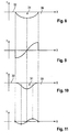
- Figure 7b circa Figure 2 and Figure 7c shows that the Figure 7b Enlarged detail marked with Vllc. It can clearly be seen that, according to the invention, an improved transition between the road surface 32 and the longitudinal wall 31.1 can be designed. This advantage is demonstrated by the Figures 8 to 11 further clarified.
- Figure 8 is the result of the cross-section.
- Figure 6b resulting contour of the road marking 31 is drawn as a curve in a coordinate system.
- Figure 10 shows analogously the curve of the lane marking acc. Figure 7b .
Description
Die Erfindung betrifft einen Schneidkörper zur Erzeugung einer Fahrbahnmarkierung mit einem um eine Rotationsachse drehbaren Rotationskörper, der eine Vielzahl von Schneidelementen auswechselbar aufnehmen kann, die eine Schneidkurve festlegen.The invention relates to a cutting body for generating a road marking with a rotating body rotatable about an axis of rotation, which can interchangeably accommodate a plurality of cutting elements which define a cutting curve.
Aus der
Die Fahrbahnmarkierungen haben somit die Funktion und Aufgabe der Abgabe eines akustischen und haptischen Warnsignals. Diese Geräuschquelle wird aber von der an die Fahrbahn anschließende Umgebung mitunter als störend empfunden. Ein weiterer Nachteil der bekannten Fahrbahnmarkierungen ergibt sich beim Überfahren mit einem Zweirad. Dabei wird das Zweirad seitlich versetzt, was beim Fahrer dann gefährliche Lenkkorrekturen auslösen kann. Wenn sich in den Vertiefungen Regenwasser ansammelt, dann kann zudem die Fahrsituation des Zweirades instabil werden.The road markings thus have the function and task of emitting an acoustic and haptic warning signal. However, this noise source is sometimes perceived as disturbing by the surrounding area adjacent to the road. Another disadvantage of the known road markings arises when driving over with a two-wheeler. The two-wheeler is moved laterally, which can then trigger dangerous steering corrections for the driver. If rainwater collects in the depressions, the driving situation of the two-wheeler can also become unstable.
In der
Aus dem Stand der Technik sind auch Schneidkörper bekannt, mit denen sich Fahrbahnmarkierungen in die Straßenoberfläche einfräsen lassen. Die
Aus der
Es ist Aufgabe der Erfindung, einen Schneidkörper bereit zu stellen, mit dem sich Fahrbahnmarkierungen mit verbesserten Anwendereigenschaften erzeugen lassen.It is an object of the invention to provide a cutting body with which road markings with improved user properties can be produced.
Diese Aufgabe wird mit den Merkmalen des Anspruches 1 gelöst. Demgemäß ist es vorgesehen, dass die Schneidkurve in Richtung der Rotationsachse einen konkaven Schneidbereich bildet, und dass sich beidseitig an den konvexen Schneidbereich jeweils ein konkaver Schneidbereich anschließt.This object is achieved with the features of claim 1. Accordingly, it is provided that the cutting curve forms a concave cutting area in the direction of the axis of rotation, and that a concave cutting area connects to the convex cutting area on both sides.
Mit dem erfindungsgemäßen Schneidkörper können Vertiefungen für Fahrbahnmarkierungen gefräst werden, bei denen die Fahrbahnoberfläche stetig über den konvexen Bereich in den konkaven Boden übergeleitet wird. Dies hat den Vorteil, dass der Reifen eines Fahrzeuges sanfter in die Vertiefung gelangt. Hierdurch wird eine Reduzierung der Geräuschentwicklung erreicht, wobei jedoch noch ein ausreichender Schallpegel und insbesondere ein ausreichendes haptisches Warnsignal zur Erzeugung von Aufmerksamkeit beim Fahrer entsteht.With the cutting body according to the invention, depressions for road markings can be milled, in which the road surface is continuously transferred over the convex area into the concave floor. This has the advantage that the tire of a vehicle gets into the depression more gently. This results in a reduction in the development of noise, but there is still a sufficient sound level and in particular a sufficient haptic warning signal for generating attention from the driver.
Die Geometrie der Fahrbahnmarkierung ermöglicht auch ein problemloseres Überfahren mit einem Zweirad und dass ein den Fahrer verunsichernder Seitenverzug vermindert wird. Darüber hinaus wird mit dem konvexen Bereich der Vertiefung das von der Vertiefung gebildete Volumen verkleinert. Somit kann sich darin weniger Wasser sammeln, was die Gefahr für die Instabilität eines Zweirades bei nasser Fahrbahn deutlich verringert.The geometry of the lane markings also enables a two-wheeler to drive over it more easily and to reduce side distortion that unsettles the driver. In addition, the volume formed by the depression is reduced with the convex region of the depression. This means that less water can collect in it, which significantly reduces the risk of instability of a two-wheeler on wet roads.
Erfindungsgemäß ist vorgesehen, dass der Rotationskörper eine Befestigungsfläche aufweist, auf der Werkzeughalter befestigt sind, die die Schneidelemente auswechselbar aufnehmen können, dass die Befestigungsfläche einen dem konvexen Schneidbereich zugeordneten konvexen Befestigungsabschnitt und einen dem konkaven Schneidbereich zugeordneten konkaven Befestigungsabschnitt aufweist. Mit einem solchen Rotationskörper kann die Schneidkurve auf einfache Weise unter Verwendung gleicher Meißelhalter und Schneidelemente erzeugt werden.According to the invention, it is provided that the rotary body has a fastening surface on which tool holders are fastened, which can receive the cutting elements interchangeably, that the fastening surface has a convex fastening section assigned to the convex cutting region and one has the concave cutting portion associated concave attachment portion. With such a rotating body, the cutting curve can be generated in a simple manner using the same bit holder and cutting elements.
Gemäß einer bevorzugten Ausgestaltungsvariante des Schneidkörpers kann es vorgesehen sein, dass wenigstens einer der konkaven Schneidbereiche an dem dem konvexen Schneidbereich abgewandten Ende in einem zur Rotationsachse parallelen Endbereich ausläuft. Auf diese Weise wird in der Vertiefung ein harmonischer Übergang zur Fahrbahnoberfläche erzeugt, der besonders robust mechanischen Beanspruchungen widersteht.According to a preferred embodiment of the cutting body, it can be provided that at least one of the concave cutting areas ends at the end facing away from the convex cutting area in an end area parallel to the axis of rotation. In this way, a harmonious transition to the road surface is created in the recess, which withstands particularly robust mechanical loads.
Wenn vorgesehen ist, dass der Radius des konvexen Schneidbereichs zwischen 200 mm und 400 mm beträgt, und/oder dass der Radius des konkaven Schneidbereichs zwischen 400 mm und 800 mm beträgt, dann ergeben sich an der Vertiefung entsprechende Geometrien, die bei vermindertem Einfluss auf die Reifenführung eine ausreichende Geräuschentwicklung entstehen lassen.If it is provided that the radius of the convex cutting area is between 200 mm and 400 mm, and / or that the radius of the concave cutting area is between 400 mm and 800 mm, then corresponding geometries result at the depression, which have a reduced influence on the Sufficient noise can be generated by the tire guide.
Ein erfindungsgemäßer Schneidkörper kann dadurch gekennzeichnet sein, dass in dem von dem Rotationskörper umschlossenen Hohlbereich ein Befestigungsflansch angeordnet ist und dass der Befestigungsflansch an dem dem konvexen Schneidbereich zugeordneten Innenwandungsabschnitt an den Rotationskörper angekoppelt ist. Der Befestigungsflansch ist somit in dem durch den konvexen Schneidbereich gebildeten verdickten Abschnitt des Rotationskörpers festigkeitsoptimiert fixiert.A cutting body according to the invention can be characterized in that a fastening flange is arranged in the hollow area enclosed by the rotating body and that the fastening flange is coupled to the rotating body on the inner wall section assigned to the convex cutting area. The fastening flange is thus fixed in the thickened section of the rotary body formed by the convex cutting area in a manner optimized for strength.
Mit den erfindungsgemäßen Schneidkörpern können Fahrbahnmarkierungen in Form von Vertiefungen erzeugt werden, wobei die Vertiefungen zwei seitliche, in Fahrbahnlängsrichtung verlaufende Längswände aufweisen, die in einen Bodenbereich übergehen, wobei die Vertiefungen von zwei quer zur Fahrbahnrichtung verlaufenden Querwänden begrenzt sind, wobei ein konvexer Bereich zumindest einer der Längswände in einen konkaven Bereich des Bodens übergeleitet ist und/oder wobei der konvexe Bereich zumindest einer der Seitenwände in die Fahrbahnoberfläche übergeleitet ist. Auf diese Weise entstehen Vertiefungen, die die Seitenführung des Rades wenig beeinträchtigen.With the cutting bodies according to the invention, road markings can be produced in the form of depressions, the depressions having two lateral longitudinal walls running in the longitudinal direction of the road, which merge into a floor area, the depressions being delimited by two transverse walls running transverse to the direction of the road, with a convex area at least one of the longitudinal walls in a concave area of the floor is transferred and / or wherein the convex area of at least one of the side walls is transferred into the road surface. In this way, depressions are created that have little impact on the lateral guidance of the wheel.
Denkbar ist es auch, dass die Querwände einen konkaven Bereich aufweisen, der mittelbar oder unmittelbar in die Fahrbahnoberfläche übergeleitet ist. Dann entsteht beim Auftreffen des Rades auf die Querwand ein ausreichend hoher Schalldruck. Die Vertiefungen können zur Bildung der Fahrbahnmarkierung zueinander in gleichem Teilungsraster beabstandet sein oder es ist denkbar, dass die einzelnen Vertiefungen unmittelbar aneinandergrenzen.It is also conceivable for the transverse walls to have a concave region which is passed directly or indirectly into the road surface. Then a sufficiently high sound pressure is created when the wheel hits the transverse wall. The depressions can be spaced apart from one another in the same division grid to form the road marking, or it is conceivable that the individual depressions directly adjoin one another.
Die Erfindung wird im Folgenden anhand von in den Zeichnungen dargestellten Ausführungsbeispiels näher erläutert. Es zeigen:
- Figur 1
- einen Vertikalschnitt durch eine Fahrbahn und einen Schneidkörper,
- Figur 2
- einen Vertikalschnitt durch eine Fahrbahn,
- Figuren 3 und 4
- in schematischer Darstellung verschiedene Fahrbahnmarkierungen,
- Figur 5a
- einen Schneidkörper gemäß dem Stand der Technik in schematischer Seitenansicht,
- Figuren 5b und 5c
- eine Fahrbahnmarkierung, gefertigt mit einem Schneidkörper gem.
Figur 5a , - Figur 6a
- einen Schneidkörper gemäß dem Stand der Technik in schematischer Seitenansicht,
- Figuren 6b und 6c
- eine Fahrbahnmarkierung, gefertigt mit einem Schneidkörper gem.
Figur 6a , - Figur 7a
- den erfindungsgemäßen Schneidkörper gem.
Figur 1 in schematischer Seitenansicht - Figuren 7b und 7c
- eine Fahrbahnmarkierung, gefertigt mit einem Schneidkörper gem.
Figur 7a , - Figur 8
- die Kontur der Fahrbahnmarkierung gem.
Figur 6b bzw. 6c in einem Koordinatensystem, - Figur 9
- die 1. Ableitung der sich aus
Figur 8 ergebenden Kurve, Figur 10- die Kontur der Fahrbahnmarkierung gem.
Figur 7b bzw. 7c in einem Koordinatensystem und Figur 11- die 1. Ableitung der sich aus
Figur 10 ergebenden Kurve.
- Figure 1
- a vertical section through a roadway and a cutting body,
- Figure 2
- a vertical section through a roadway,
- Figures 3 and 4
- various road markings in a schematic representation,
- Figure 5a
- a cutting body according to the prior art in a schematic side view,
- Figures 5b and 5c
- a road marking, made with a cutting body acc.
Figure 5a , - Figure 6a
- a cutting body according to the prior art in a schematic side view,
- Figures 6b and 6c
- a road marking made with a cutting body acc.
Figure 6a , - Figure 7a
- the cutting body according to the invention.
Figure 1 in a schematic side view - Figures 7b and 7c
- a road marking, made with a cutting body acc.
Figure 7a , - Figure 8
- the contour of the lane marking acc.
Figure 6b or 6c in a coordinate system, - Figure 9
- the 1st derivative of itself
Figure 8 resulting curve, - Figure 10
- the contour of the lane marking acc.
Figure 7b or 7c in a coordinate system and - Figure 11
- the 1st derivative of itself
Figure 10 resulting curve.
Der Mantel des Rotationskörpers 10 bildet ein Tragteil 13 mit einer tonnenförmig umlaufenden Befestigungsfläche 14. Die Befestigungsfläche 14 setzt sich aus einem mittleren konvexen Befestigungsabschnitt 14.2 und zwei jeweils seitlich daran anschließenden konkaven Befestigungsabschnitten 14.1 zusammen. Dabei gehen die konkaven Befestigungsabschnitte 14.1 unmittelbar in den konvexen Befestigungsabschnitt 14.2 über. Auf den beiden Befestigungsabschnitten 14.1 und 14.2 sind Meißelhalterwechselsysteme, bestehend aus einem Basisteil und einem daran auswechselbar befestigbaren Meißelhalter 20, montiert. Dabei sind die Basisteile mit den Befestigungsabschnitten 14.1, 14.2 verschweißt. Die Basisteile sind zueinander in Umfangsrichtung versetzt angeordnet, so dass sich Räum- und Ladewenden ergeben, die spiralförmig auf den Befestigungsabschnitten 14.1, 14.2 verlaufen.The jacket of the
Denkbar ist auch eine Erfindungsausgestaltung, bei der die Meißelhalter 20 direkt auf die Befestigungsabschnitte 14.1, 14.2 aufgeschweißt sind, so dass auf Basisteile verzichtet werden kann. Die Meißelhalter 20 weisen Meißelaufnahmen auf, in denen Meißel 21, vorzugsweise Rundschaftmeißel, auswechselbar aufgenommen werden können. Die Meißel 21 sind mit Schneidelementen ausgestattet, die bei einer Drehung des Rotationskörpers 10 um die Drehachse R eine Schneidkurve 15 festlegen. Dabei bildet die Schneidkurve 15 eine Art Hüllkurve.An embodiment of the invention is also conceivable, in which the chisel holders 20 are welded directly onto the fastening sections 14.1, 14.2, so that base parts can be dispensed with. The chisel holders 20 have chisel holders in which chisels 21, preferably round-shank chisels, can be exchangeably received. The
Wie die
Mit dem Schneidkörper lassen sich Fahrbahnmarkierungen, bestehend aus linienförmig hintereinander angeordneten Vertiefungen 31, in die Fahrbahn 30 einfräsen.The cutting body can be used to mill road markings, consisting of
Die dabei entstehende Geometrie der Vertiefung 31 ist in
In den
Bildet man nun von diesen Kurven (gem.
Demgegenüber verdeutlicht die
Claims (7)
- Cutting body for producing a road marking, comprising a rotational body (10) which can be rotated about an axis of rotation (R) and which can interchangeably receive a plurality of cutting elements (21) which define a cutting curve (15)
wherein the rotational body (10) has a fastening surface (14) on which there are fastened tool holders (20) which can interchangeably receive the cutting elements (21),
wherein the cutting curve (15) forms a convex cutting region (15.2) in the direction of the axis of rotation (R),
and wherein the fastening surface (14) has a convex fastening portion (14.2) assigned to the convex cutting region (15.2),
characterized in that the convex cutting region (15.2) is adjoined on both sides by a respective concave cutting region (15.1),
and in that the fastening surface (14) has a concave fastening portion (14.1) assigned to the concave cutting region (15.1). - Cutting body according to Claim 1
characterized in that, at the end facing away from the convex cutting region (15.2) and relative to the axis of rotation, the cutting curve (15) has a slope which approaches zero or has there a substantially axis-parallel profile. - Cutting body according to Claim. 1 or 2,
characterized in that the cutting curve, or the individual regions of the cutting curve, follow a real function, in particular a trigonometric function. - Cutting body according to anus of Claims 1. to 3,
characterized in that the radius (R2) of the convex cutting region (15.2) is between 200 mm and 400 mm. - Cutting body according to one of Claims 1 to 4,
characterized in that the radius (R1) of the concave cutting region (15.1) is between 400 mm and 800 mm. - Cutting body according to one of Claims 1 to 5,
characterized in that the rotational body (10) is designed in the form of a roller. - Cutting body according to one of Claims 1 to 6,
characterized in that the fastening flange (11) is arranged in the hollow region enclosed by the rotational body (10) and in that the fastening flange (11) is coupled to the rotational body (10) in the inner wall portion assigned to the convex cutting region (15.2).
Applications Claiming Priority (1)
| Application Number | Priority Date | Filing Date | Title |
|---|---|---|---|
| DE102009034766A DE102009034766A1 (en) | 2009-07-25 | 2009-07-25 | Cutting body for generating a lane marking and lane marking |
Publications (4)
| Publication Number | Publication Date |
|---|---|
| EP2292844A2 EP2292844A2 (en) | 2011-03-09 |
| EP2292844A3 EP2292844A3 (en) | 2012-03-28 |
| EP2292844B1 EP2292844B1 (en) | 2014-06-11 |
| EP2292844B2 true EP2292844B2 (en) | 2020-07-29 |
Family
ID=43038066
Family Applications (1)
| Application Number | Title | Priority Date | Filing Date |
|---|---|---|---|
| EP10164541.4A Active EP2292844B2 (en) | 2009-07-25 | 2010-06-01 | Cutter for generating a road marking and road marking |
Country Status (6)
| Country | Link |
|---|---|
| US (1) | US8491219B2 (en) |
| EP (1) | EP2292844B2 (en) |
| JP (1) | JP5049373B2 (en) |
| CN (2) | CN101962931A (en) |
| CA (1) | CA2707289C (en) |
| DE (1) | DE102009034766A1 (en) |
Cited By (1)
| Publication number | Priority date | Publication date | Assignee | Title |
|---|---|---|---|---|
| RU2799220C1 (en) * | 2022-10-20 | 2023-07-04 | Федеральное государственное бюджетное образовательное учреждение высшего образования "Казанский государственный архитектурно-строительный университет" (КазГАСУ) | Method of application of noise band |
Families Citing this family (10)
| Publication number | Priority date | Publication date | Assignee | Title |
|---|---|---|---|---|
| DE102011109450A1 (en) * | 2011-08-04 | 2013-02-07 | Bomag Gmbh | Milling rotor for processing soil material and tillage machine with such a rotor |
| CN103194948A (en) * | 2013-03-28 | 2013-07-10 | 郭子也 | Pavement with durable and energy-saving traffic safety line and paving method thereof |
| DE102014015584B4 (en) * | 2014-10-21 | 2018-10-25 | Bomag Gmbh | Milling roller and ground milling machine with such a milling drum |
| CN105335546B (en) * | 2015-09-08 | 2019-04-23 | 陕西高速机械化工程有限公司 | A kind of milling measurement method of maintenance of surface |
| US20170211245A1 (en) | 2016-01-21 | 2017-07-27 | Diamond Surface, Inc. | Reduced volume sonic noise alert pattern grinder & method |
| WO2018098380A1 (en) * | 2016-11-23 | 2018-05-31 | Maxwell Garlon J | Smoothing drum with precision leveling for smoothing pavement surfaces |
| WO2018175672A1 (en) | 2017-03-23 | 2018-09-27 | Waterblasting, Llc | Apparatus for forming rumble strip grooves in a roadway |
| US20220151166A1 (en) * | 2020-11-13 | 2022-05-19 | 106 Reforestation, Llc | Roller for use with heavy equipment |
| CN112554014A (en) * | 2020-11-27 | 2021-03-26 | 于江波 | Linear cutting mechanism moving support for cement road construction |
| CN115573231B (en) * | 2022-09-03 | 2024-04-26 | 邯郸市华威公路设计咨询有限公司 | Road marking grinds equipment in highway engineering construction |
Citations (4)
| Publication number | Priority date | Publication date | Assignee | Title |
|---|---|---|---|---|
| US5582490A (en) † | 1994-09-22 | 1996-12-10 | Wirtgen America, Inc. | Rumble strip cutter wheel |
| DE10007253A1 (en) † | 2000-02-17 | 2001-08-23 | Manfred Blessing | Milling roller, especially for processing road surfaces, has bits arranged so circular paths of mutually offset bits overlap and bit heads engage surface with overlapping effective regions. |
| US20050077776A1 (en) † | 2003-08-26 | 2005-04-14 | Terry Hansen | Reinforced concrete milling/cutting mandrel |
| US7029072B1 (en) † | 2002-03-11 | 2006-04-18 | Wirtgen America, Inc. | Modified rumble strip cutter |
Family Cites Families (15)
| Publication number | Priority date | Publication date | Assignee | Title |
|---|---|---|---|---|
| US1529797A (en) * | 1921-10-26 | 1925-03-17 | William D Gray | Land roller |
| US3516712A (en) * | 1968-08-19 | 1970-06-23 | Jeffrey Galion Inc | Mining machine for mining material from the entire face |
| US3554606A (en) * | 1969-01-22 | 1971-01-12 | Christensen Diamond Prod Co | Cutters for forming highway paint receiving grooves |
| US3774969A (en) * | 1971-12-22 | 1973-11-27 | Nat Mine Service Co | Continuous mining machine |
| US4310199A (en) * | 1979-09-20 | 1982-01-12 | National Mine Service Company | Cutter drum assembly for a continuous mining machine |
| US4999952A (en) * | 1989-06-09 | 1991-03-19 | Union Broach | Method and apparatus for manufacturing K-files and reamers |
| US5676490A (en) * | 1996-04-08 | 1997-10-14 | Nelson; Dale J. | Machine for cutting highway rumble strips |
| JPH1129905A (en) * | 1997-06-06 | 1999-02-02 | Nippon Hodo Co Ltd | Construction method of attention attracting pavement |
| US6547484B2 (en) | 2001-02-14 | 2003-04-15 | Dustrol, Inc. | Apparatus for cutting rumble strips in a road surface |
| US20040005190A1 (en) * | 2002-07-08 | 2004-01-08 | Gerhard Jakits | Device and method for selectively milling the surface of a roadway |
| DE10245394C1 (en) * | 2002-09-28 | 2003-12-04 | Man Takraf Foerdertechnik Gmbh | Cutting roller for continuous open-cast mining device has mini-disc cutters fitted along counter-rotating transport screws extending between each end of roller mantle and its centre |
| US7029370B2 (en) * | 2003-02-24 | 2006-04-18 | Coneqtec Corp. | Grinding machines for depression patterns along roads |
| CN2858746Y (en) * | 2005-11-30 | 2007-01-17 | 天津鼎盛工程机械有限公司 | Two-way spiral milling device |
| JP4018128B1 (en) * | 2007-02-27 | 2007-12-05 | 正司建設株式会社 | Pavement surface groove cutting machine |
| CN101275383A (en) * | 2007-03-30 | 2008-10-01 | 上海宝冶建设有限公司 | Device for cutting and chamfering pavement expansion joint and method of use thereof |
-
2009
- 2009-07-25 DE DE102009034766A patent/DE102009034766A1/en active Pending
-
2010
- 2010-06-01 EP EP10164541.4A patent/EP2292844B2/en active Active
- 2010-06-11 CA CA2707289A patent/CA2707289C/en not_active Expired - Fee Related
- 2010-06-23 CN CN2010102071200A patent/CN101962931A/en active Pending
- 2010-06-23 CN CN2010202343234U patent/CN201908249U/en not_active Expired - Lifetime
- 2010-06-28 US US12/824,790 patent/US8491219B2/en active Active
- 2010-07-26 JP JP2010167082A patent/JP5049373B2/en not_active Expired - Fee Related
Patent Citations (4)
| Publication number | Priority date | Publication date | Assignee | Title |
|---|---|---|---|---|
| US5582490A (en) † | 1994-09-22 | 1996-12-10 | Wirtgen America, Inc. | Rumble strip cutter wheel |
| DE10007253A1 (en) † | 2000-02-17 | 2001-08-23 | Manfred Blessing | Milling roller, especially for processing road surfaces, has bits arranged so circular paths of mutually offset bits overlap and bit heads engage surface with overlapping effective regions. |
| US7029072B1 (en) † | 2002-03-11 | 2006-04-18 | Wirtgen America, Inc. | Modified rumble strip cutter |
| US20050077776A1 (en) † | 2003-08-26 | 2005-04-14 | Terry Hansen | Reinforced concrete milling/cutting mandrel |
Non-Patent Citations (2)
| Title |
|---|
| GARDNER, L., ET AL: "Comparison of Football Shaped Rumble Strips Versus Rectangular Rumble Strips", REPORT NO. K-TRAN: KSU-00-4P2, September 2007 (2007-09-01), Manhattan, Kansas, pages i-vi, 94 - 103 † |
| RYS ET AL: "Evaluation of Football Shaped Rumble Strips Versus Rectangular Rumble Strips", JOURNAL OF THE TRANSPORTATION RESEARCH FORUM, vol. 47, no. 2, 2008, pages 41 - 54 † |
Cited By (1)
| Publication number | Priority date | Publication date | Assignee | Title |
|---|---|---|---|---|
| RU2799220C1 (en) * | 2022-10-20 | 2023-07-04 | Федеральное государственное бюджетное образовательное учреждение высшего образования "Казанский государственный архитектурно-строительный университет" (КазГАСУ) | Method of application of noise band |
Also Published As
| Publication number | Publication date |
|---|---|
| EP2292844B1 (en) | 2014-06-11 |
| EP2292844A3 (en) | 2012-03-28 |
| CA2707289A1 (en) | 2011-01-25 |
| JP5049373B2 (en) | 2012-10-17 |
| US20110020063A1 (en) | 2011-01-27 |
| US8491219B2 (en) | 2013-07-23 |
| CN201908249U (en) | 2011-07-27 |
| DE102009034766A1 (en) | 2011-02-03 |
| EP2292844A2 (en) | 2011-03-09 |
| CA2707289C (en) | 2014-06-10 |
| CN101962931A (en) | 2011-02-02 |
| JP2011026949A (en) | 2011-02-10 |
Similar Documents
| Publication | Publication Date | Title |
|---|---|---|
| EP2292844B2 (en) | Cutter for generating a road marking and road marking | |
| EP1731010B2 (en) | Vehicle | |
| EP2685007B1 (en) | Roue de fraisage pour une fraise pour paroi moulée | |
| EP3040478B1 (en) | Self-propelled street milling machine for milling street surfaces, and method for machining street surfaces with a street milling machine | |
| EP2636799B1 (en) | Drilling tool for making a subterraneous curtain wall and method of making such wall | |
| DE102016206721A1 (en) | Cutting tool for improved chip removal and method for its production | |
| DE2919774A1 (en) | MULTI-CUTTING CHISEL FOR A CUTTING TURN DRUM | |
| DE1427702C (en) | ||
| DE102012206250A1 (en) | Cutting tool, in particular saw blade, for a machine tool | |
| EP2479344A1 (en) | Rotor box for a floor milling machine with guide device for milled material and floor milling machine with such a rotor box | |
| DE102010045388A1 (en) | Carbide head for a tool for processing solid material | |
| EP2837740B1 (en) | Self-propelled construction machine for working on road surfaces or ground surfaces and method for cooling the milling tools of a milling drum of a self-propelled construction machine | |
| DE102013008618A1 (en) | Tool combination for a milling drum, milling tool holder and milling drum | |
| EP3477127B1 (en) | Screw for screwing into a hole | |
| EP2635415A1 (en) | Grinding and/or cutting tool for a machine tool with an oscillating drive | |
| DE202009010140U1 (en) | Cutting body for generating a lane marking and lane marking | |
| AT504993A1 (en) | CUTTING PLATE FOR WHEEL SET MACHINING TOOLS | |
| DE2448753C2 (en) | Cutting head for tunneling and extraction machines in mining and tunnel construction | |
| EP3241948A1 (en) | Rotary milling cutter with a plurality of interchangeable tool heads and tool head for such a rotary milling cutter | |
| DE2528418A1 (en) | Groove cutting device for road surfaces - has drum cutting system with intermediate drum segments and drive shafts | |
| DE10247214B4 (en) | Milling device and method for road surface treatment | |
| WO2017076833A1 (en) | Chamfering tool with guide for eliminating vibrations | |
| DE514861C (en) | Sharpening tool for surface treatment of stones | |
| AT526575A2 (en) | Processing unit for a self-propelled device for edge processing of already installed curbs, self-propelled device with such a device and edge processing method | |
| DE202022105484U1 (en) | Processing unit for a self-propelled device for edge processing of already installed curbs and self-propelled device with such |
Legal Events
| Date | Code | Title | Description |
|---|---|---|---|
| PUAI | Public reference made under article 153(3) epc to a published international application that has entered the european phase |
Free format text: ORIGINAL CODE: 0009012 |
|
| AK | Designated contracting states |
Kind code of ref document: A2 Designated state(s): AL AT BE BG CH CY CZ DE DK EE ES FI FR GB GR HR HU IE IS IT LI LT LU LV MC MK MT NL NO PL PT RO SE SI SK SM TR |
|
| AX | Request for extension of the european patent |
Extension state: BA ME RS |
|
| PUAL | Search report despatched |
Free format text: ORIGINAL CODE: 0009013 |
|
| AK | Designated contracting states |
Kind code of ref document: A3 Designated state(s): AL AT BE BG CH CY CZ DE DK EE ES FI FR GB GR HR HU IE IS IT LI LT LU LV MC MK MT NL NO PL PT RO SE SI SK SM TR |
|
| AX | Request for extension of the european patent |
Extension state: BA ME RS |
|
| RIC1 | Information provided on ipc code assigned before grant |
Ipc: E01F 9/047 20060101ALI20120223BHEP Ipc: E01C 23/09 20060101AFI20120223BHEP |
|
| 17P | Request for examination filed |
Effective date: 20120928 |
|
| 17Q | First examination report despatched |
Effective date: 20130327 |
|
| GRAP | Despatch of communication of intention to grant a patent |
Free format text: ORIGINAL CODE: EPIDOSNIGR1 |
|
| INTG | Intention to grant announced |
Effective date: 20140210 |
|
| GRAS | Grant fee paid |
Free format text: ORIGINAL CODE: EPIDOSNIGR3 |
|
| GRAA | (expected) grant |
Free format text: ORIGINAL CODE: 0009210 |
|
| AK | Designated contracting states |
Kind code of ref document: B1 Designated state(s): AL AT BE BG CH CY CZ DE DK EE ES FI FR GB GR HR HU IE IS IT LI LT LU LV MC MK MT NL NO PL PT RO SE SI SK SM TR |
|
| REG | Reference to a national code |
Ref country code: GB Ref legal event code: FG4D Free format text: NOT ENGLISH |
|
| REG | Reference to a national code |
Ref country code: CH Ref legal event code: EP |
|
| REG | Reference to a national code |
Ref country code: IE Ref legal event code: FG4D Free format text: LANGUAGE OF EP DOCUMENT: GERMAN |
|
| REG | Reference to a national code |
Ref country code: AT Ref legal event code: REF Ref document number: 672331 Country of ref document: AT Kind code of ref document: T Effective date: 20140715 |
|
| REG | Reference to a national code |
Ref country code: DE Ref legal event code: R096 Ref document number: 502010007171 Country of ref document: DE Effective date: 20140724 |
|
| REG | Reference to a national code |
Ref country code: SE Ref legal event code: TRGR |
|
| PG25 | Lapsed in a contracting state [announced via postgrant information from national office to epo] |
Ref country code: GR Free format text: LAPSE BECAUSE OF FAILURE TO SUBMIT A TRANSLATION OF THE DESCRIPTION OR TO PAY THE FEE WITHIN THE PRESCRIBED TIME-LIMIT Effective date: 20140912 Ref country code: FI Free format text: LAPSE BECAUSE OF FAILURE TO SUBMIT A TRANSLATION OF THE DESCRIPTION OR TO PAY THE FEE WITHIN THE PRESCRIBED TIME-LIMIT Effective date: 20140611 Ref country code: LT Free format text: LAPSE BECAUSE OF FAILURE TO SUBMIT A TRANSLATION OF THE DESCRIPTION OR TO PAY THE FEE WITHIN THE PRESCRIBED TIME-LIMIT Effective date: 20140611 Ref country code: NO Free format text: LAPSE BECAUSE OF FAILURE TO SUBMIT A TRANSLATION OF THE DESCRIPTION OR TO PAY THE FEE WITHIN THE PRESCRIBED TIME-LIMIT Effective date: 20140911 |
|
| REG | Reference to a national code |
Ref country code: NL Ref legal event code: VDEP Effective date: 20140611 |
|
| REG | Reference to a national code |
Ref country code: LT Ref legal event code: MG4D |
|
| PG25 | Lapsed in a contracting state [announced via postgrant information from national office to epo] |
Ref country code: LV Free format text: LAPSE BECAUSE OF FAILURE TO SUBMIT A TRANSLATION OF THE DESCRIPTION OR TO PAY THE FEE WITHIN THE PRESCRIBED TIME-LIMIT Effective date: 20140611 Ref country code: HR Free format text: LAPSE BECAUSE OF FAILURE TO SUBMIT A TRANSLATION OF THE DESCRIPTION OR TO PAY THE FEE WITHIN THE PRESCRIBED TIME-LIMIT Effective date: 20140611 |
|
| PG25 | Lapsed in a contracting state [announced via postgrant information from national office to epo] |
Ref country code: RO Free format text: LAPSE BECAUSE OF FAILURE TO SUBMIT A TRANSLATION OF THE DESCRIPTION OR TO PAY THE FEE WITHIN THE PRESCRIBED TIME-LIMIT Effective date: 20140611 Ref country code: SK Free format text: LAPSE BECAUSE OF FAILURE TO SUBMIT A TRANSLATION OF THE DESCRIPTION OR TO PAY THE FEE WITHIN THE PRESCRIBED TIME-LIMIT Effective date: 20140611 Ref country code: EE Free format text: LAPSE BECAUSE OF FAILURE TO SUBMIT A TRANSLATION OF THE DESCRIPTION OR TO PAY THE FEE WITHIN THE PRESCRIBED TIME-LIMIT Effective date: 20140611 Ref country code: CZ Free format text: LAPSE BECAUSE OF FAILURE TO SUBMIT A TRANSLATION OF THE DESCRIPTION OR TO PAY THE FEE WITHIN THE PRESCRIBED TIME-LIMIT Effective date: 20140611 Ref country code: PT Free format text: LAPSE BECAUSE OF FAILURE TO SUBMIT A TRANSLATION OF THE DESCRIPTION OR TO PAY THE FEE WITHIN THE PRESCRIBED TIME-LIMIT Effective date: 20141013 Ref country code: ES Free format text: LAPSE BECAUSE OF FAILURE TO SUBMIT A TRANSLATION OF THE DESCRIPTION OR TO PAY THE FEE WITHIN THE PRESCRIBED TIME-LIMIT Effective date: 20140611 |
|
| PG25 | Lapsed in a contracting state [announced via postgrant information from national office to epo] |
Ref country code: NL Free format text: LAPSE BECAUSE OF FAILURE TO SUBMIT A TRANSLATION OF THE DESCRIPTION OR TO PAY THE FEE WITHIN THE PRESCRIBED TIME-LIMIT Effective date: 20140611 Ref country code: IS Free format text: LAPSE BECAUSE OF FAILURE TO SUBMIT A TRANSLATION OF THE DESCRIPTION OR TO PAY THE FEE WITHIN THE PRESCRIBED TIME-LIMIT Effective date: 20141011 Ref country code: PL Free format text: LAPSE BECAUSE OF FAILURE TO SUBMIT A TRANSLATION OF THE DESCRIPTION OR TO PAY THE FEE WITHIN THE PRESCRIBED TIME-LIMIT Effective date: 20140611 |
|
| REG | Reference to a national code |
Ref country code: DE Ref legal event code: R026 Ref document number: 502010007171 Country of ref document: DE |
|
| PLBI | Opposition filed |
Free format text: ORIGINAL CODE: 0009260 |
|
| 26 | Opposition filed |
Opponent name: CATERPILLAR INC. Effective date: 20150310 |
|
| PLAX | Notice of opposition and request to file observation + time limit sent |
Free format text: ORIGINAL CODE: EPIDOSNOBS2 |
|
| PG25 | Lapsed in a contracting state [announced via postgrant information from national office to epo] |
Ref country code: IT Free format text: LAPSE BECAUSE OF FAILURE TO SUBMIT A TRANSLATION OF THE DESCRIPTION OR TO PAY THE FEE WITHIN THE PRESCRIBED TIME-LIMIT Effective date: 20140611 Ref country code: DK Free format text: LAPSE BECAUSE OF FAILURE TO SUBMIT A TRANSLATION OF THE DESCRIPTION OR TO PAY THE FEE WITHIN THE PRESCRIBED TIME-LIMIT Effective date: 20140611 |
|
| REG | Reference to a national code |
Ref country code: DE Ref legal event code: R026 Ref document number: 502010007171 Country of ref document: DE Effective date: 20150310 |
|
| REG | Reference to a national code |
Ref country code: FR Ref legal event code: PLFP Year of fee payment: 6 |
|
| PG25 | Lapsed in a contracting state [announced via postgrant information from national office to epo] |
Ref country code: SI Free format text: LAPSE BECAUSE OF FAILURE TO SUBMIT A TRANSLATION OF THE DESCRIPTION OR TO PAY THE FEE WITHIN THE PRESCRIBED TIME-LIMIT Effective date: 20140611 |
|
| PLBB | Reply of patent proprietor to notice(s) of opposition received |
Free format text: ORIGINAL CODE: EPIDOSNOBS3 |
|
| REG | Reference to a national code |
Ref country code: DE Ref legal event code: R082 Ref document number: 502010007171 Country of ref document: DE Representative=s name: HERRMANN, JOCHEN, DIPL.-ING., DE |
|
| PG25 | Lapsed in a contracting state [announced via postgrant information from national office to epo] |
Ref country code: MC Free format text: LAPSE BECAUSE OF FAILURE TO SUBMIT A TRANSLATION OF THE DESCRIPTION OR TO PAY THE FEE WITHIN THE PRESCRIBED TIME-LIMIT Effective date: 20140611 |
|
| REG | Reference to a national code |
Ref country code: CH Ref legal event code: PL |
|
| PG25 | Lapsed in a contracting state [announced via postgrant information from national office to epo] |
Ref country code: LU Free format text: LAPSE BECAUSE OF FAILURE TO SUBMIT A TRANSLATION OF THE DESCRIPTION OR TO PAY THE FEE WITHIN THE PRESCRIBED TIME-LIMIT Effective date: 20150601 |
|
| REG | Reference to a national code |
Ref country code: IE Ref legal event code: MM4A |
|
| PG25 | Lapsed in a contracting state [announced via postgrant information from national office to epo] |
Ref country code: LI Free format text: LAPSE BECAUSE OF NON-PAYMENT OF DUE FEES Effective date: 20150630 Ref country code: IE Free format text: LAPSE BECAUSE OF NON-PAYMENT OF DUE FEES Effective date: 20150601 Ref country code: CH Free format text: LAPSE BECAUSE OF NON-PAYMENT OF DUE FEES Effective date: 20150630 |
|
| REG | Reference to a national code |
Ref country code: FR Ref legal event code: PLFP Year of fee payment: 7 |
|
| PG25 | Lapsed in a contracting state [announced via postgrant information from national office to epo] |
Ref country code: MT Free format text: LAPSE BECAUSE OF FAILURE TO SUBMIT A TRANSLATION OF THE DESCRIPTION OR TO PAY THE FEE WITHIN THE PRESCRIBED TIME-LIMIT Effective date: 20140611 |
|
| RIC2 | Information provided on ipc code assigned after grant |
Ipc: E01C 23/09 20060101ALI20161215BHEP Ipc: E01F 9/529 20160101AFI20161215BHEP |
|
| APBM | Appeal reference recorded |
Free format text: ORIGINAL CODE: EPIDOSNREFNO |
|
| APBP | Date of receipt of notice of appeal recorded |
Free format text: ORIGINAL CODE: EPIDOSNNOA2O |
|
| APAH | Appeal reference modified |
Free format text: ORIGINAL CODE: EPIDOSCREFNO |
|
| APBQ | Date of receipt of statement of grounds of appeal recorded |
Free format text: ORIGINAL CODE: EPIDOSNNOA3O |
|
| PG25 | Lapsed in a contracting state [announced via postgrant information from national office to epo] |
Ref country code: HU Free format text: LAPSE BECAUSE OF FAILURE TO SUBMIT A TRANSLATION OF THE DESCRIPTION OR TO PAY THE FEE WITHIN THE PRESCRIBED TIME-LIMIT; INVALID AB INITIO Effective date: 20100601 |
|
| REG | Reference to a national code |
Ref country code: FR Ref legal event code: PLFP Year of fee payment: 8 |
|
| PG25 | Lapsed in a contracting state [announced via postgrant information from national office to epo] |
Ref country code: SM Free format text: LAPSE BECAUSE OF NON-PAYMENT OF DUE FEES Effective date: 20140611 Ref country code: CY Free format text: LAPSE BECAUSE OF FAILURE TO SUBMIT A TRANSLATION OF THE DESCRIPTION OR TO PAY THE FEE WITHIN THE PRESCRIBED TIME-LIMIT Effective date: 20140611 Ref country code: BG Free format text: FAILURE TO ELECT DOMICILE IN THE NATIONAL COUNTRY Effective date: 20150630 |
|
| PG25 | Lapsed in a contracting state [announced via postgrant information from national office to epo] |
Ref country code: BE Free format text: LAPSE BECAUSE OF NON-PAYMENT OF DUE FEES Effective date: 20150630 |
|
| PG25 | Lapsed in a contracting state [announced via postgrant information from national office to epo] |
Ref country code: TR Free format text: LAPSE BECAUSE OF FAILURE TO SUBMIT A TRANSLATION OF THE DESCRIPTION OR TO PAY THE FEE WITHIN THE PRESCRIBED TIME-LIMIT Effective date: 20140611 |
|
| PLAB | Opposition data, opponent's data or that of the opponent's representative modified |
Free format text: ORIGINAL CODE: 0009299OPPO |
|
| R26 | Opposition filed (corrected) |
Opponent name: CATERPILLAR INC. Effective date: 20150310 |
|
| REG | Reference to a national code |
Ref country code: FR Ref legal event code: PLFP Year of fee payment: 9 |
|
| PG25 | Lapsed in a contracting state [announced via postgrant information from national office to epo] |
Ref country code: MK Free format text: LAPSE BECAUSE OF FAILURE TO SUBMIT A TRANSLATION OF THE DESCRIPTION OR TO PAY THE FEE WITHIN THE PRESCRIBED TIME-LIMIT Effective date: 20140611 |
|
| PG25 | Lapsed in a contracting state [announced via postgrant information from national office to epo] |
Ref country code: AL Free format text: LAPSE BECAUSE OF FAILURE TO SUBMIT A TRANSLATION OF THE DESCRIPTION OR TO PAY THE FEE WITHIN THE PRESCRIBED TIME-LIMIT Effective date: 20140611 |
|
| RIC2 | Information provided on ipc code assigned after grant |
Ipc: E01C 23/09 20060101ALI20161215BHEP Ipc: E01F 9/529 20160101AFI20161215BHEP |
|
| APBU | Appeal procedure closed |
Free format text: ORIGINAL CODE: EPIDOSNNOA9O |
|
| PUAH | Patent maintained in amended form |
Free format text: ORIGINAL CODE: 0009272 |
|
| STAA | Information on the status of an ep patent application or granted ep patent |
Free format text: STATUS: PATENT MAINTAINED AS AMENDED |
|
| 27A | Patent maintained in amended form |
Effective date: 20200729 |
|
| AK | Designated contracting states |
Kind code of ref document: B2 Designated state(s): AL AT BE BG CH CY CZ DE DK EE ES FI FR GB GR HR HU IE IS IT LI LT LU LV MC MK MT NL NO PL PT RO SE SI SK SM TR |
|
| REG | Reference to a national code |
Ref country code: DE Ref legal event code: R102 Ref document number: 502010007171 Country of ref document: DE |
|
| REG | Reference to a national code |
Ref country code: SE Ref legal event code: RPEO |
|
| REG | Reference to a national code |
Ref country code: AT Ref legal event code: MM01 Ref document number: 672331 Country of ref document: AT Kind code of ref document: T Effective date: 20200601 |
|
| PG25 | Lapsed in a contracting state [announced via postgrant information from national office to epo] |
Ref country code: AT Free format text: LAPSE BECAUSE OF NON-PAYMENT OF DUE FEES Effective date: 20200601 |
|
| P01 | Opt-out of the competence of the unified patent court (upc) registered |
Effective date: 20230525 |
|
| PGFP | Annual fee paid to national office [announced via postgrant information from national office to epo] |
Ref country code: FR Payment date: 20230619 Year of fee payment: 14 Ref country code: DE Payment date: 20230620 Year of fee payment: 14 |
|
| PGFP | Annual fee paid to national office [announced via postgrant information from national office to epo] |
Ref country code: SE Payment date: 20230622 Year of fee payment: 14 |
|
| PGFP | Annual fee paid to national office [announced via postgrant information from national office to epo] |
Ref country code: GB Payment date: 20230622 Year of fee payment: 14 |